
Xtreme CL-55PLC68-OB - Monitor Peerless-AV - Free user manual and instructions
Find the device manual for free Xtreme CL-55PLC68-OB Peerless-AV in PDF.


| Product Type | Commercial LCD Monitor |
| Brand | Peerless-AV |
| Model | Xtreme CL-55PLC68-OB |
| Screen Size | 55 inches (diagonal) |
| Resolution | 1920 x 1080 (Full HD) |
| Brightness | 500 cd/m² |
| Contrast Ratio | 4000:1 |
| Viewing Angle | 178° horizontal / 178° vertical |
| Aspect Ratio | 16:9 |
| Inputs | HDMI, VGA, DisplayPort, USB |
| Power Consumption | 150W (typical) |
| VESA Mount | 400 x 400 mm |
| Weight | 25 kg (approx) |
| Dimensions (WxHxD) | 1245 x 715 x 80 mm |
| Operating Temperature | 0°C to 40°C |
| Features | Built-in speakers, RS232 control, OSD |
| Cleaning | Use a soft dry cloth. |
| Safety | Do not expose to moisture. |
| Repairability | Contact authorized service center. |
| Spare Parts | Available from Peerless-AV. |
Frequently Asked Questions - Xtreme CL-55PLC68-OB Peerless-AV
User questions about Xtreme CL-55PLC68-OB Peerless-AV
0 question about this device. Answer the ones you know or ask your own.
Ask a new question about this device
Download the instructions for your Monitor in PDF format for free! Find your manual Xtreme CL-55PLC68-OB - Peerless-AV and take your electronic device back in hand. On this page are published all the documents necessary for the use of your device. Xtreme CL-55PLC68-OB by Peerless-AV.
USER MANUAL Xtreme CL-55PLC68-OB Peerless-AV
natural_image
Exterior view of a modern black-framed display screen (no text or symbols visible)CONTENTS
General Safety Precautions ....3
FCC Caution....5
FCC Statement....5
Notice 5
Relevant Information ....5
System Installation And Electrical Requirements 6
Electrical Code 6
Power Source 6
Set Up Instructions....7
What's In The Box 7
Ambient Light Sensor....7
Connecting Cables....8
Source Connection Guide....8
Cable Seals....9
Installation Of The Rear Cover Plate....9
Connect To The Power Source....10
Prepare Your Display For Mounting 11
Prepare The Display For Usage....12
Battery Installation And Replacement ....12
Power On/Off the Display....12
Operating Instructions 13
Using The Remote Control....13
Rear Keypad Controls....13
Navigating The On-Screen Menu ....14
Picture 14
Audio 14
Setup 14
Time 15
Lock 15
Channel....15
(RS-232C) Serial Control Of The Display 16
Control Codes 16
Communication Settings 16
Tips....17
Troubleshooting....17
Care Of Screen 17
Mobile Telephone Warning 17
End Of Life Directives ....17
License Agreement & Trademark Notice ....17
Product Specifications ....18
Warranty 23
GENERAL SAFETY PRECAUTIONS
WARNING
RISK OF ELECTRICAL SHOCK
To reduce the risk of electric shock, do not disassemble the unit under any circumstances. No user serviceable parts inside. All product services should be done by the Peerless-AV certified service personnel.
Read before operating equipment
Thank you for purchasing our product. Before using it, please read this user manual carefully and follow the instructions correctly for safe operation. Please keep this manual handy for future reference. Also, please be sure to always include this user manual in the packaging when transferring or transporting this product to a different location.
Batteries Installed Warning
CAUTION - Danger of explosion if batteries are incorrectly re-placed. Replace only with the same or equivalent type. Even through the remote is designed for outdoor usage, the batteries should not be exposed to excessive heat due to sunlight, fire or other heat sources.
CAUTION:
To reduce the risk of electric shock, do not perform any servicing other than that contained in the operating instructions unless you are qualified to do so.
- Read these instructions.
- Keep these instructions.
- Heed all warnings.
- Follow all instructions.
- Do not defeat the safety purpose of the polarized or grounding type electrical plug. A polarized plug has two blades with one wider than the other. A grounding type plug has two blades and a third grounding prong. The wide blade or the third prong are provided for your safety. If the provided plug does not fit into your outlet, consult an electrician for replacement of the obsolete outlet.
- Protect the electrical cord from being walked on or pinched particularly at plugs, convenience receptacles, and the point where they exit from the apparatus.
- Refer all servicing to qualified service personnel. Servicing is required when the apparatus has been damaged in any way, such as electrical-supply cord or plug is damaged, does not operate normally, or has been dropped.
- Only use attachments/accessories specified by the manufacturer.
- In case of emergency such as fire or electric shock caused by the product, immediately contact 911 or proper emergency police/fi re service agencies in your country.
- If monitor or glass is broken, do not come in contact with the liquid crystal and handle with care.
- Follow instructions for wall, shelf or ceiling mounting as recommended by the manufacturer.
- An outdoor antenna should not be located near overhead electrical lines or any electrical circuits.
- If an outside antenna is connected to the receiver, confirm that the antenna system is grounded to protect against voltage surges and built up static charges Section 810 of the National Electric Code, ANSI/NFPA No 70-1984, provides information with respect to proper grounding for the mast and supporting structure, grounding of the lead-in wire to an antenna discharge unit, size of grounding connectors, location of antenna discharge unit, connection to grounding electrodes and requirements for the grounding electrode.
- Use properly rated electrical voltage. Use of non-rated voltage may cause fire, electric shock and severe damages to the product.
-
Do not open the cabinet under any circumstances. High voltage inside of this product may cause electric shock.
-
Do NOT, under any circumstances, modify or disassemble this product as it may cause fire, electric shock, or severe damages to the product. Also any unauthorized modifications made to the product automatically void product warranty.
- Never touch antenna lines or wires, electrical cables or plugs when lightning or thunder is present as it may cause electric shock.
- Any severe physical impact on the product may cause certain components to fall out of place within and break, which may cause fire or electric shock. In such event, do not operate the product. Contact the manufacturer for support.
- Periodically clean dust off the electrical plug to keep it clean and dry, ensuring proper and safe operation of the product.
- Do NOT destroy, process, or place close to any heat source; do NOT bend or twist electrical cords, electrical plugs, cables, or wires with excessive force; do NOT place any heavy object on the display as all of the above may cause damage resulting in fire or electric shock.
- Do NOT touch electrical plugs with wet hands.
- Always make sure to plug in the electrical plug firmly and completely. Incompletely placed electrical plugs may cause fire or electric shock due to built up heat emission.
- Do NOT use any non-rated electrical sockets or power strips with many other devices jointly plugged in. The wire of non-designated capacity may cause fire due to built up heat emission. Try to use a single, directly dedicated and rated GFCI electrical outlet for the product for safe operation.
- In case of product malfunction or unusual events such as electrical burning smell, smoke, or loss of content signals on TV/Display due to internal overheating, immediately turn off and unplug the electrical cord and contact the manufacturer.
- Do NOT install the product in unstable locations or near moving objects, constantly vibrating equipment, or uneven surfaces. Follow mounting instructions properly for safe operation of the product as improper installation may cause products to fall.
- Do NOT install the product near any poisonous gas or chemically unstable atmosphere as it may cause fire.
- Do NOT install the product near any strong magnetic or electrical current field as it may cause fire, electric shock, or severe damages to the product and the product may be subject to electromagnetic radiation, causing deterioration of the picture quality.
- Do NOT leave any fire source, such as candles, close to or on the product as it may be a cause for fire or damages to the product.
- Do NOT move or transport the product with any cables (electrical cables, content connectivity cables) plugged in to the source devices. Damages may occur to the cables, plugs, or jointing connectors of the cables due to forcible bending and stress, which may cause damages to the waterproof seal of the product, making it subject to fire, electric shock, or shorted circuit.
- When unplugging the electrical plug or other cables, always pull using the plug and not the cord. Improper pulling of the cords or cables may cause damage to the waterproof seal, making it subject to fire, electric shock, or a shorted circuit.
- Do NOT climb on the product.
- Outdoor displays should always be carried and supported by at least two persons.
- Do NOT use any other electrical cords or connection cables than what is provided with the product or from the manufacturer directly. Use of untested, unauthorized, or substituted electrical cords or connection cables may be a cause for malfunction, fire, electric shock, or severe damages to the product. Also such use of improper or undesignated electrical cords or connection cables will void product warranty.
- Always leave the Power Off when plugging or unplugging the electrical cords or connection cables to avoid electric shock or damages to the product.
- Do NOT use any chemical such as paint thinner or benzene to clean the product's exterior. It may cause scratches on the surface, erasing proper indications, identification labels, or instructions on the exterior, which may be a cause for misuse and improper operation of the product.
- The socket-outlet shall be installed near the equipment and shall be easily accessible.
- The product is to be secured to building before operation.
FCC CAUTION
To assure continued compliance and possible undesirable interference, ferrite cores may be used when connecting this display to video equipment; and maintain at least 400mm (15.75 inches) spacing to other peripheral device.
FCC STATEMENT
This equipment has been tested and found to comply with the limits for a Class A digital device, pursuant to Part 15 of the FCC Rule. These limits are designed to provide reasonable protection against harmful interference in a residential installation. This equipment generates, uses and can radiate radio frequency energy and, if not installed and used in accordance with these instructions, may cause harmful interference to radio communications. However, there is no guarantee that interference will not occur in a particular installation. If this equipment does cause harmful interference to radio or television reception, which can be determined by turning the equipment off and on, the user is encouraged to try to correct the interference by one or more of the following measures:
- Reorient or relocate the receiving antenna.
- Increase the separation between the equipment and receiver.
- Connect the equipment into an outlet on a circuit different from that to which the receiver is connected.
- Consult the dealer or an experienced radio/display technician for help.
This device complies with Part 15 of the FCC Rules. Operation is subject to the following two conditions:
- This device may not cause harmful interference.
- This device must accept any interference received, including interference that may cause undesired operation.
Notice
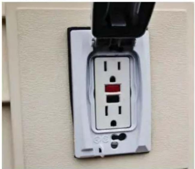
CAUTION: Please use the electrical cord provided with this display. If an electrical cord is not supplied with this equipment, please contact your supplier. Only plug equipment into receptacles with GFCI protection.
IMPORTANT: Peerless-AV is not responsible for any issues created by water present at the plug/receptacle insertion point.
Relevant Information
Record your display's model and serial number here for future reference. Keep this user manual in an accessible location in the event settings need to be changed or service is desired.
Note: Your display serial number can be found on the box and underneath the rear cover plate
Model Number ____
Serial Number ____
SYSTEM INSTALLATION AND ELECTRICAL REQUIREMENTS
Electrical Code
Note: To the display system installer: This reminder is provided to call attention to Article 820-44 of the National Electric Code that provides guidelines for proper grounding and, in particular, specifies that the cable ground shall be connected to the grounding system of the facility. Outlet shall be installed near the equipment and shall be easily accessible.

Note: Installation shall incorporate UL Listed external surge protection rated 2500 Vpk or less, for 150 to 300 Vac mains, installed in accordance with Article 285 of ANSI/NFPA 70 or applicable local codes.
Power Source
The display must be connected to a main socket outlet with a protective grounding connection. The main plug is used as the disconnect device and shall remain readily accessible.
This display operates on 100-240 volts 50-60 Hz, AC current. Insert the power cord into a 120 volts 60 Hz outlet. Never connect the display to direct current or anything other than the specified voltage. To prevent electric shock from the display, do not use with an extension cord, receptacle, or other outlet unless the blades and ground terminal can be fully inserted to prevent blade exposure.
CAUTION: Never remove the back cover of the display as this can expose you to very high voltages and other hazards. If the display does not operate properly, unplug the display and call your authorized dealer or service center.
CAUTION: Double pole/neutral fusing (ISO 3869. No 5036)
SET UP INSTRUCTIONS
Important:
- The display is equipped with protective glass; however, it is best practice to never apply pressure to the screen display area which may compromise the integrity of the display. The manufacturer's warranty does not cover user abuse or improper installations.
- All cables and cable covers MUST be connected and attached prior to installation on mount.
- When routing cables through the cable entry make sure that the cables are formed in such a way as to remove any stress on the connectors.
- Installation shall be in accordance with the applicable parts of Chapter 8 of ANSI/NFPA70.
What's In The Box
| Display | Power Cord (CAB-0075) |
| Remote (410-0049) | 8mm Socket Bit (PUR-0026) |
| Rear Cover Plate (CST-1005) | 5.5mm Socket Bit (PUR-0025) |
| (8) M4 x 10mm screws (SCR-0042) | Cord Stress Relief Retaining Bracket (MET-0016) |
| User Guide | (2) M3 x 8mm phillips screws (SCR-0007) |
| Remote Control Guide |
Ambient Light Switch
This display is equipped with an ambient light switch which allows the display to have two brightness modes to adjust to the environment the display is located in. The switch is located on the back of the display.
- Ambient light sensor on: Your display's brightness will automatically dim as ambient lighting decreases.
- Ambient light sensor off (depicted below): Your display settings will remain at full brightness even if the ambient lighting of the room or environment changes.
Hint: Set the ambient light switch to your desired setting before installing the display's rear cover plate to avoid having to remove the display's rear cover plate to access the switch.
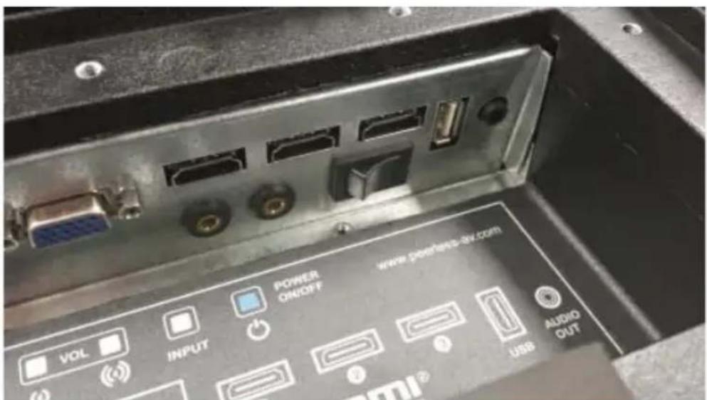
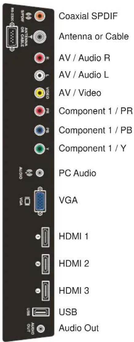
Source Connection Guide
Connect cables from the source devices to their appropriate connector on the display.
Note: Your display's serial number can be found on the box and underneath the rear cover plate.
For display with serial number that starts with 12 or 14

For display with serial number that starts with 15
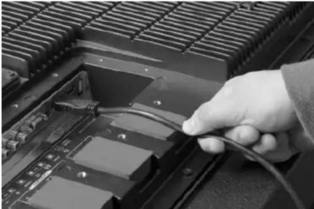
Cable Seals
- Plug cables into proper input connection.
- Run cable across foam gasket block.
Notes: a. If running one cable per block, run cable over middle of cable block.
b. If running more than one cable on a block, ensure that cables are at least 14 " apart to allow for proper sealing.
natural_image
Close-up of a hand holding a cable inserted into a computer motherboard (no visible text or symbols)- Cables will be sealed when rear cover plate is attached and screwed into place.
Installation Of The Rear Cover Plate
- Place cover plate directly over cables aligning holes with screw inserts.
- Apply pressure to center of cover plate.
Note: Foam gasket block should compress when pressure is applied.
- Screw in screws until they will no longer tighten.
Note: Do not over torque screws as they may strip and damage the cable seal.

natural_image
Close-up of a hand using a drill bit on a metal workpiece (no visible text or symbols)- When all screws are installed properly, the cables should appear to be completely encapsulated between the cable gland and the back cover plate.

natural_image
Close-up of a metallic heating element with grid pattern and mounting holes (no visible text or symbols)Connect To The Power Source
- Connect the supplied electrical cord to the display ensuring the slot in the cord plug aligns with the tab on the display plug.

natural_image
Close-up of a mechanical component with a circular housing and a cylindrical shaft, mounted on a vertical metal grate (no visible text or symbols)- Hand tighten the electrical cord nut to the display.

natural_image
Close-up of a hand adjusting a black mechanical component on a car radiator grille (no visible text or symbols)- Install the electrical cord stress relief retaining bracket. Failure to install the retaining bracket may lead to damage resulting in injury or death.

natural_image
Close-up of a red and yellow screwdriver inserted into a black electrical socket on a striped metal panel (no text or symbols visible)- Insert the prongs of the electrical cord into the electrical outlet and ensure the plug is fully seated. The display should only be connected to an electrical outlet that has a GFCI circuit.
natural_image
White electrical outlet wall socket with black plastic cover and red indicator lights (no text or symbols visible)Prepare Your Display For Mounting
Note: Install cables prior to mounting your display. Cable entry cover may be obstructed once the display is mounted.
IMPORTANT:
- Do not apply pressure to the screen display area which may compromise the integrity of the display. The manufacturer's warranty does not cover user abuse or improper installations.
- For portrait mounting rotate the display so that the rear cover plate and cord connections will be on the right when viewing the display from the front.
Wall mounting solution is not included with the unit and is sold separately. Peerless-AV provides a variety of all-weather mounting solutions. Contact your Peerless-AV representative for all-environment mounting solutions.
For your safety, only mount with an UL listed wall mount bracket that supports the weight of the display. When mounting the display outdoors or in harsh environments, only use wall mounts that are designed to resist water, rust and wind.
Examine the chart below to determine the mounting specifications for your display:
| Model | Mounting Hole Pattern | Required Mounting Screws |
| CL-42PLC68-OBCL-47PLC68-OBCL-49PLC68-OBCL-55PLC68-OB | 600mm x 400mm Four M8 screws | |
| CLP-42PLC68-OBCLP-47PLC68-OBCLP-49PLC68-OBCLP-55PLC68-OB | 400mm x 600mm Four M8 screws |
CLP-42PLC68-OB
CLP-47PLC68-OB
CLP-49PLC68-OB
CLP-55PLC68-OB


Prepare The Display For Usage
- Remove protective film from the face of the display.
- Clean the display with an approved screen cleaner or Isopropyl alcohol designated in the "Care of Display" section. Do not use window cleaners or products containing ammonia.
Remote Control Battery Installation And Replacement
The remote control is powered by two 1.5V AAA batteries installed at the factory.
To install or replace batteries:
- Remove the battery module of the remote control by removing the two screws on the end of the battery module. Slide the battery module out of the remote control.
- Insert two new "AAA" size batteries into the battery module.
- Slide the battery module back into the remote control and reinserting the two screws in the end of the battery module.
CAUTION
Incorrect usage of batteries can result in leaks or bursting. Peerless-AV recommends the following battery use:
- Do not mix battery brands.
- Do not combine new and old batteries. This can shorten the battery life or cause liquid leakage of the batteries.
- Remove dead batteries immediately to prevent battery acid from leaking into the battery compartment.
- Do not touch exposed battery acid as it may injure skin.
- Remove the batteries if you do not intend to use the remote control for a long period of time.
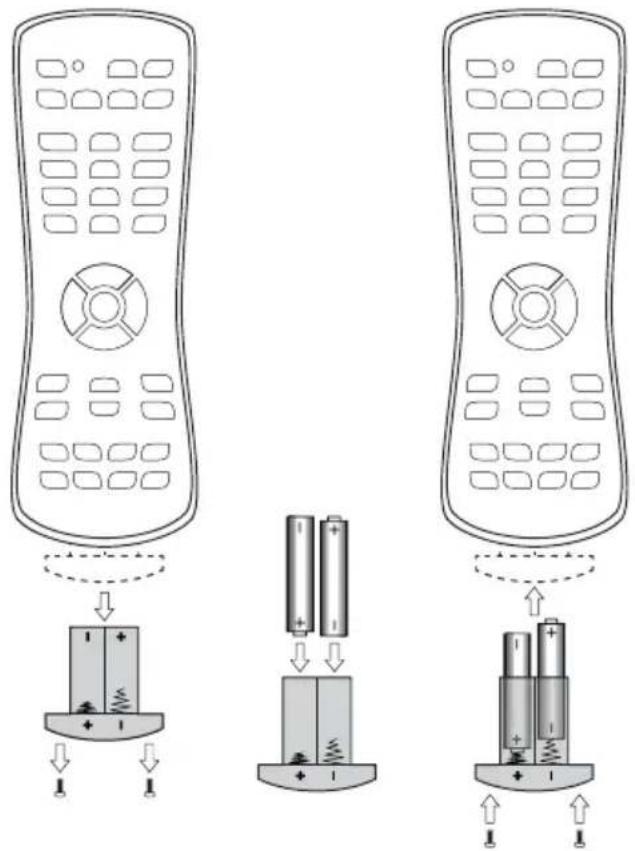
Power On/Off Your New Display
Power on your display by using the remote control or the rear power key as shown below. The display will power on but image may not appear for a few seconds as it completes its power up sequence.
Remote control
Point the remote control at the IR sensor located in the upper right corner of the display and press the power key.

natural_image
Hand holding a green remote control panel on a black surface (no visible text or symbols)Rear Power Key
To access the rear keypad follow the procedures found in the "Rear Keypad Controls" section. Press the blue power key.

OPERATING INSTRUCTIONS
Using The Remote Control
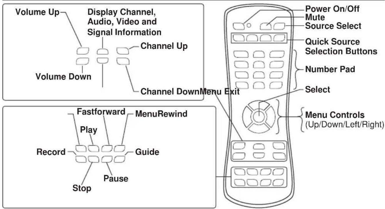
Rear Keypad Controls
To access the keypad, the cover plate located on the back of the display must be removed. Remove the fasteners using the supplied 5.5 mm socket bit. Reinstall the keypad cover to prevent any water from entering the unit.
DIRECT MODE: Allows for quick access to source selection, volume settings and channel selection. MENU MODE: Press the MENU button to access MENU MODE and activate the On Screen Display (OSD). For a description of OSD operation refer to the next section.
The keypad buttons are assigned as indicated in the table below.

flowchart
graph TD
    A["DIRECT MODE"] --> B["Channel Down"]
    A --> C["Select"]
    A --> D["Menu"]
    A --> E["Volume Down"]
    A --> F["Volume Up"]
    A --> G["Input Select"]
    A --> H["On/Off"]
    I["MENU MODE"] --> J["-"]
    I --> K["Select"]
    I --> L["Menu"]
    I --> M["Left"]
    I --> N["Right"]
    I --> O["Auto Config"]
    I --> P["On/Off"]
    Q[" "] --> R[" "]
    Q --> S[" "]
    Q --> T[" "]
    Q --> U[" "]
    Q --> V[" "]
    Q --> W[" "]
    Q --> X[" "]
    Q --> Y[" "]
    Q --> Z[" "]
Navigating The On Screen Menu
Pressing the menu key on the remote or the onboard controls will cause the On Screen Display (OSD) main page to be displayed with five menu tabs: Picture, Audio, Time, Setup, Lock and Channel. Use the cursor keys to move through the various sub menus. Pressing the menu key again will move the selection back one level. Press exit to quit.
| Picture | |
| Picture Mode | StandardDynamicTheaterPersonal |
| Contrast | 50 |
| Brightness | 50 |
| Color | 50 |
| Tint | 50 |
| Sharpness | 50 |
| Color Temp. | NormalCoolWarm |
| Zoom Mode | 16:9FullZoomPoint To Point4:3 |
| 3DNR | OffWeakMiddleStrong |
| Backlight | 0 |
| Audio | |
| Equalizer | StandardMusicMovieSportPersonal |
| 120 Hz | 50 |
| 500 Hz | 50 |
| 1.5 KHz | 50 |
| 5 KHz | 50 |
| 10 KHz | 50 |
| Audio Language | EnglishSpanishFrench |
| Digital Output (SPDIF) | PCM/Raw |
| Surround | On/Off |
| AVC | On/Off |
| Setup | |
| Menu Languages | EnglishSpanishFrenchGerman(EUK Mode Only) |
| Transparency (Menu Transparency) | 0%25%50%75%100% |
| Restore Defaults | Factory Reset All Options |
| Setup Wizard | |
| Software Update (USB) | |
| Blue Screen | On/Off |
| HDMI MODE | VideoPC |
Navigating The On Screen Menu
Pressing the menu key on the remote or the onboard controls will cause the On Screen Display (OSD) main page to be displayed with five menu tabs: Picture, Audio, Time, Setup, Lock and Channel. Use the cursor keys to move through the various sub menus. Pressing the menu key again will move the selection back one level. Press exit to quit.
| Time | |
| Sleep Timer off | 5min10min15min30min60min90min120min180min240min |
| Time Zone | Select time zone |
| DST | On/Off |
| Time Format | 12-hour24-hour |
| Auto Sync | On/Off |
| Clock | Enter Current Time |
| Wake Up | Enter desired time when display will turn on |
| NOSIGNAL SHUT | On/Off |
| Lock | |
| System Lock | Enter Password to lock the menu |
| Channel | |
| Air/Cable | Choose between Antenna and Cable |
| Auto Scan | Searches for available channels |
| Favorite | Shows favorite channels |
| Show/Hide | show or hide channels |
| Channel No. | Displays list of channels |
| Channel Label | Change channel names |
| DTV Signal | Displays channel info and signal strength |
Attach an RS-232C cable (commercially available) to the supplied Din/D-Sub RS-232C for the connections.
Note: This operation system should be used by a person who is accustomed to using computers.
peerless-AV®
Xtreme Displays
RS 232 Codes
Menu: A0, F0, 55, FF, 4E, B1
Right: A0, F0, 55, FF, 05, FA
OK: A0, F0, 55, FF, 02, FD
Down: A0, F0, 55, FF, 0D, F2
Up: A0, F0, 55, FF, 17, E8
Left: A0, F0, 55, FF, 0C, F3
Source: A0, F0, 55, FF, 01, FE
(1): A0, F0, 55, FF, 42, BD
(2): A0, F0, 55, FF, 43, BC
(3): A0, F0, 55, FF, OF, F0
(4): A0, F0, 55, FF, 1E, E1
(5): A0, F0, 55, FF, 1D, E2
(6): A0, F0, 55, FF, 1C, E3
(7): A0, F0, 55, FF, 18, E7
(8): A0, F0, 55, FF, 45, BA
(9): A0, F0, 55, FF, 4C, B3
(0) A0, F0, 55, FF, 56, A9
Exit: A0, F0, 55, FF, 1B, E4
Power On: A0, F0, 55, FF, AE, 51
Power Off: A0, F0, 55, FF, AD, 52
Power On/Off: A0, F0, 55, FF, 0B, F4
Volume +: A0, F0, 55, FF, 0A, F5
Volume -: A0, F0, 55, FF, 40, BF
Channel +: A0, F0, 55, FF, 55, AA
Channel -: A0, F0, 55, FF, 5A, A5
Mute: A0, F0, 55, FF, 14, EB
Sleep: A0, F0, 55, FF, 53, AC
AV: A0, F0, 55, FF, ED, 12
VGA: A0, F0, 55, FF, EA, 15
HDMI Toggle: A0, F0, 55, FF, EC, 13
HDMI1: A0, F0, 55, FF, DE, 21
HDMI2: A0, F0, 55, FF, DF, 20
HDMI3: A0, F0, 55, FF, E0, 1F
S-VIDEO: A0, F0, 55, FF, E4, 1B
TV: A0, F0, 55, FF, E8, 17
DTV: A0, F0, 55, FF, E9, 16
Component: A0, F0, 55, FF, E7, 18
USB: A0, F0, 55, FF, 57, A8
PMODE: A0, F0, 55, FF, 4B, B4
Zoom: A0, F0, 55, FF, 51, AE
Surround: A0, F0, 55, FF, C7, 38
SMODE: A0, F0, 55, FF, 5B, A4
VOL 25%: A0, F0, 55, FF, 21, DE
VOL 50%: A0, F0, 55, FF, 22, DD
VOL 75%: A0, F0, 55, FF, 23, DC
VOL 100%: A0, F0, 55, FF, 24, DB
Brightness 25%: A0, F0, 55, FF, 26, D9
Brightness 50%: A0, F0, 55, FF, 27, D8
Brightness 75%: A0, F0, 55, FF, 28, D7
Brightness 100%: A0, F0, 55, FF, 29, D6
COM Settings
| Baud Rate: | 38400 |
| Data Bits: | 8 |
| Parity: | None |
| Stop Bits: | 1 |
TIPS
Troubleshooting
| No Picture | Check that the display is turned on.Is the power cord inserted into a power outlet?Test the power outlet by plugging in another device into the outlet. |
| Remote Control Doesn’t Work | Make sure there is a direct path between the remote control and the IR receiver located at the Peerless-AV logo at the bottom center of the display.Press the “TV” button on the universal remote control to select the TV as the device being controlled.Was the shipping tab removed and the battery re-installed correctly?Install new battery. |
| Picture Appears Slowly After Switching On | This is normal; the display image is disabled during the start up process.After an image appears it can take several minutes for the LCD display to reach it’s normal operating brightness.On first use activate power control by pressing power button on remote. |
Care Of The Display
Do not rub or strike the display with anything hard as this may scratch, mar, or even damage the screen permanently.
Never use ammonia or any product containing ammonia, as it will damage the anti-glare coating on the face of the glass. Only use Isopropyl alcohol or an approved screen cleaner to clean the display face.
Protective covers are available for Peerless-AV Xtreme Displays. Contact your Peerless-AV representative to get the right cover for your display.
Unplug the power cord before cleaning the screen. Dust the display by wiping the screen and the cabinet with a soft, clean cloth and if the screen requires additional cleaning, use a clean, damp cloth. Do not use liquid cleaners, aerosol cleaners, or solvents of any kind.
Mobile Telephone Warning
Keep your mobile telephone away from your display to avoid disturbances in the picture or sound, possibly causing permanent damage to your display.
End Of Life Directives
In an effort to produce environmentally friendly products, your new display contains materials that can be recycled and reused. At the end of your display life, specialized companies can minimize display waste by separating reusable materials from non-reusable materials. Please ensure you dispose of your display according to local regulations.
License Agreement And Trademark Notice


HDMI, the HDMI logo and High-Definition Multimedia Interface are trademarks or registered trademarks of HDMI Licensing LLC in the United States and other countries.
Manufactured under license from Dolby Laboratories, Dolby and the double-D symbol are trademarks of Dolby Laboratories
PRODUCT SPECIFICATIONS
Specifications subject to change without notice
| Display | |
| Screen Size | |
| CL-42PLC68-OB | 42" diagonal |
| CL-47PLC68-OB | 47" diagonal |
| CL-49PLC68-OB | 49" diagonal |
| CL-55PLC68-OB | 55" diagonal |
| CLP-42PLC68-OB | 42" diagonal |
| CLP-47PLC68-OB | 47" diagonal |
| CLP-49PLC68-OB | 49" diagonal |
| CLP-55PLC68-OB | 55" diagonal |
| Aspect Ratio | 16:9 |
| Resolution | 1920 x 1080 |
| Brightness | 700 cd/m ^2 |
| Backlight Adjustment | Automatic (ambient light sensor) |
| Contrast Ratio* | 1000:1, 1300:1 for 49" |
| Viewing Angle | 178° vertical/horizontal |
| Response Time | 9ms (gray to gray)8ms (gray to gray) for 49" |
* Enhanced for direct sunlight usage.
| Power | |
| AC Input | 90 VAC to 240 VAC,50 to 60 Hz |
| Power Consumption | |
| CL-42PLC68-OB | Display: 101 WTotal with Heater: 801 W |
| CL-47PLC68-OB | Display: 135 WTotal with Heater: 835 W |
| CL-49PLC68-OB | Display: 104 WTotal with Heater: 804 W |
| CL-55PLC68-OB | Display: 145 WTotal with Heater: 845 W |
| CLP-42PLC68-OB | Display: 101 WTotal with Heater: 801 W |
| CLP-47PLC68-OB | Display: 135 WTotal with Heater: 835 W |
| CLP-49PLC68-OB | Display: 104 WTotal with Heater: 804 W |
| CLP-55PLC68-OB | Display: 145 WTotal with Heater: 845 W |
| TV Controller Features | |
| Analog TV | NTSC |
| Digital TV | ATSC/256QAM |
| Picture Adjustment | Brightness/Contrast/Tint/Sharpness/Color |
| Picture Mode | Standard, Dynamic, Personal, Theater |
| Color Temperature Adjustment | Cool, Normal, Warm |
| Screen Adjustment | 4:3,16:9, Zoom, Point to Point |
| Clock, Sleep Timer | Yes |
| MTS | Yes |
| V-chip | Yes |
| Closed Caption | Yes |
| Electronic Program Guide | Yes |
| Noise Reduction | Yes |
| 3-D Comb Filter and De-interlace | Yes |
| Mute | Yes |
| OSD Language | English, French, Spanish |
| Environmental | |
| Operating Temperature | -40°F to 140°F |
| Storage Temperature | 0°F to 124°FIf the storage area ambient temperature is expected to be outside of this range, the unit must be connected to electricity (failure to do so, will result in damage to the LCD) |
| IP Rating | IP68 |
| Nema Rating | 6 |
| Safety/EMC | FCC Class A |
| Mechanical | |
| Display Size: | (W x H xD) |
| CL-42PLC68-OB | 39.2" x 23.2" x 5.6" |
| CL-47PLC68-OB | 43.6" x 25.7" x 5.6" |
| CL-49PLC68-OB | 44.5" x 26.0" x 5.7" |
| CL-55PLC68-OB | 50.4" x 29.6" x 6.0" |
| CLP-42PLC68-OB | 23.2" x 39.2" x 5.6" |
| CLP-47PLC68-OB | 25.7" x 43.6" x 5.6" |
| CLP-49PLC68-OB | 26.0" x 44.5" x 5.7" |
| CLP-55PLC68-OB | 29.6" x 50.4" x 6.0" |
| Enclosure Color | Black |
| Enclosure Glass | Anti-refl ective |
| VESA Mount | |
| CL-42PLC68-OB | 600 mm x 400 mm |
| CL-47PLC68-OB | 600 mm x 400 mm |
| CL-49PLC68-OB | 600 mm x 400 mm |
| CL-55PLC68-OB | 600 mm x 400 mm |
| CLP-42PLC68-OB | 400 mm x 600 mm |
| CLP-47PLC68-OB | 400 mm x 600 mm |
| CLP-49PLC68-OB | 400 mm x 600 mm |
| CLP-55PLC68-OB | 400 mm x 600 mm |
| Net Weight | |
| CL-42PLC68-OB | 82 lbs |
| CL-47PLC68-OB | 98 lbs |
| CL-49PLC68-OB | 99.5 lbs |
| CL-55PLC68-OB | 138 lbs |
| CLP-42PLC68-OB | 82 lbs |
| CLP-47PLC68-OB | 98 lbs |
| CLP-49PLC68-OB | 99.5 lbs |
| CLP-55PLC68-OB | 138 lbs |
| Shipping Size | (W x H x D) |
| CL-42PLC68-OB | 42-1/2" x 10-3/4" x 26" |
| CL-47PLC68-OB | 49-1/4" x 10-11/16" x 30" |
| CL-49PLC68-OB | 49-13/16" x 30-3/16" x 10-7/8" |
| CL-55PLC68-OB | 55-7/8" x 10-3/4" x 33-7/8" |
| CLP-42PLC68-OB | 42-1/2" x 10-3/4" x 26" |
| CLP-47PLC68-OB | 49-1/4" x 10-11/16" x 30" |
| CLP-49PLC68-OB | 49-13/16" x 30-3/16" x 10-7/8" |
| CLP-55PLC68-OB | 55-7/8" x 10-3/4" x 33-7/8" |
| Shipping Weight | |
| CL-42PLC68-OB | 90 lbs |
| CL-47PLC68-OB | 108 lbs |
| CL-49PLC68-OB | 108.5 lbs |
| CL-55PLC68-OB | 151 lbs |
| CLP-42PLC68-OB | 90 lbs |
| CLP-47PLC68-OB | 108 lbs |
| CLP-49PLC68-OB | 108.5 lbs |
| CLP-55PLC68-OB | 151 lbs |
| Input/Output Connections | |
| TV Input | Coax (x1), 75 ohm, NTSC, ATSC, 64 QAM, 256QAM |
| VGA Input | 15 pin D-SUB (x1), Up to 1920x1080@60HZ |
| HDMI Input | HDMI (x3), 480i, 480p, 576i, 576p, 720p, 1080i, 1080p |
| CVBS Input | RCA (x1) |
| YPbPr Input | RCA (x1), 480i, 480p, 720p, 1080i |
| VGA Stereo Audio Input | 3.5mm Accessory Jack (x1) |
| CVBS Stereo Audio Input | RCA (x1) |
| YPbPr Stereo Audio Input | RCA (x1) |
| Audio Stereo | 3.5mm Stereo (x1) |
| Output | 3.5mm Left Channel (x1)3.5mm Right Channel (x1) |
| RS232 Control | 9 pin D-SUB (Female) (x1) |
| S/PDIF Digital Audio Output | RCA (x1) |
ENG This page was intentionally left blank.
ENG This page was intentionally left blank.
ENG This page was intentionally left blank.
WARRANTY
peerless-AV®
Outdoor FHD TV/Display
CL-42PLC68-OB, CL-47PLC68-OB, CL-55PLC68-OB, CLP-42PLC68-OB, CLP-47PLC68-OB, CLP-55PLC68-OB CL-49PLC68-OB, CLP-49PLC68-OB
TWO YEAR PARTS & LABOR LIMITED WARRANTY
Terms of Peerless-AV®
Limited Warranty:
The Peerless-AV Outdoor TV/Display is warranted to be free of defects in material and workmanship from the time of purchase by the original owner. If this product is found and proved to be defective under the terms and conditions of this warranty, Peerless-AV will repair or replace defective parts with new and/or reconditioned parts at no charge for the parts and labor to the original owner, subject to the terms and conditions of this Limited Warranty. This Limited Warranty covers failures due to defects in material or workmanship that occur during normal residential or commercial use as follows:
- Parts – the warranty period for parts is: two (2) years from the date of original purchase. During the applicable Limited Warranty period for parts, defective parts will be replaced at no charge. Parts used for the replacement will be warranted for the remainder of the original warranty period for those parts.
- Labor – the warranty period for labor is: two (2) years from the date of original purchase. During the applicable Limited Warranty period for labor, Peerless-AV will provide the labor for warranty repair at no charge for a period of two (2) years from the date of original purchase.
- Original owner must provide verification of the date of purchase when requesting Limited Warranty Services. A copy of the original Dated Sales Receipt is required together with the product to obtain service under this Limited Warranty.
- All repairs must be performed by a Peerless-AV Authorized Service Provider.
- Customer is responsible for returning (including any freight and shipping costs) defective unit to a Peerless-AV Authorized Service Provider. If the product is found to have no defects, the customer will be responsible for return shipping costs as well.
THIS LIMITED WARRANTY DOES NOT COVER:
• Labor to uninstall and reinstall the display / TV
- Shipping damage.
- Damage caused during customer unpacking, and/or removal of packing materials.
• Damage due to improper, incorrect or insufficient AC voltage.
• Damage due to power surges or lightning strikes.
• Damage which results from fire, flood, lightning, tornado, hurricane, large hail, extremely gusty winds, sand storms, vandalism, terrorism or other acts of nature.
• Any unit which has been modified or damaged due to improper installation or failure to obey the operating instructions provided in the User Manual.
- Any failure, loss, damage or personal injury due to accident, neglect, misuse, abuse, improper operation, improper maintenance, improper storage, alteration to the unit, or failure by the consumer to follow operating instructions provided in the User Manual.
• Any owner other than the original owner.
• Any unit purchased from an unauthorized seller.
- If the original product serial number has been removed, defaces or tampered with in any way.
• Any packaging or transportation charges incurred in connection with warranty services.
- Indirect, consequential, or special damages, except as required by federal or state laws.
- Any unit tampered with, modified, adjusted or repaired by any party other than the Peerless-AV Authorized Service Provider.
- Any cosmetic damages to the surface or exterior that has been defaced or faded, or caused by normal wear and tear or exposure to chemicals, acid rain, large hail or adverse weather conditions.
- Minor cabinet blemishes or minor scratches to the exterior of the unit or other cosmetic imperfections that are not within the viewing area of the LCD
• Picture quality when installed in direct sunlight where sun is shining directly on the face of the LCD.
- Any damage, scratches or blemishes to the face of the LCD and/or exterior cabinet due to end-user cleaning.
- Dirty air waves, and/or unusual signal interference due to weak signal from multi-wire runs or weak signal from cable or satellite service providers or unusual signal interference or lack of distance when using the Digital Wireless Video/Audio Package.
- Return shipping when no defect is found.
Peerless-AV and its representatives or agents shall in no event be liable for any general, indirect or consequential damages arising out of/or caused by the use of/or the inability to use this product.
This warranty is made in lieu of all other warranties, expressed or implied, and all other liabilities on the part of Peerless-AV. Any other warranties, including the warranties of merchantability and fitness for a particular purpose are hereby disclaimed by Peerless-AV and its representatives and/or agents.
The laws of some states do not allow exclusion of implied warranties; therefore, this warranty shall be deemed modified to be consistent with such laws. This Limited Warranty gives you specific legal rights. You may also have other rights that vary from state to state.
All warranty inspections and repairs must be performed by Peerless-AV or its authorized service representations.
Customer Care: 800.865.2112 or 630.375.5100
Website: www.peerless-av.com
© 2017 Peerless Industries, Inc. All rights reserved.
peerless-AV®
Peerless-AV
2300 White Oak Circle
Aurora, IL 60502
Email: tech@peerlessmounts.com
Ph: (800) 865-2112
Fax: (800) 359-6500
www.peerless-av.com
Peerless-AV Europe
Unit 3 Watford Interchange,
Colonial Way, Watford, Herts.
WD24 4WP, United Kingdom
Customer Care
44 (0) 1923 200 100
www.peerless-av.com
Peerless-AV de Mexico



- CONTENTS
- General Safety Precautions ....3
- System Installation And Electrical Requirements 6
- Set Up Instructions....7
- Operating Instructions 13
- Navigating The On-Screen Menu ....14
- (RS-232C) Serial Control Of The Display 16
- Tips....17
- Product Specifications ....18
- Warranty 23
- GENERAL SAFETY PRECAUTIONS
- WARNING
- RISK OF ELECTRICAL SHOCK
- Read before operating equipment
- Batteries Installed Warning
- CAUTION:
- FCC CAUTION
- FCC STATEMENT
- Notice
- Relevant Information
- SYSTEM INSTALLATION AND ELECTRICAL REQUIREMENTS
- Electrical Code
- Power Source
- SET UP INSTRUCTIONS
- Important:
- Ambient Light Switch
- Source Connection Guide
- Cable Seals
- Installation Of The Rear Cover Plate
- Connect To The Power Source
- Prepare Your Display For Mounting
- Prepare The Display For Usage
- Remote Control Battery Installation And Replacement
- CAUTION
- Power On/Off Your New Display
- Remote control
- Rear Power Key
- OPERATING INSTRUCTIONS
- Rear Keypad Controls
- Navigating The On Screen Menu
- peerless-AV®
- Xtreme Displays
- RS 232 Codes
- TIPS
- Care Of The Display
- Mobile Telephone Warning
- End Of Life Directives
- License Agreement And Trademark Notice
- PRODUCT SPECIFICATIONS
- WARRANTY
- TWO YEAR PARTS & LABOR LIMITED WARRANTY
- Terms of Peerless-AV®
- THIS LIMITED WARRANTY DOES NOT COVER:
Brand : Peerless-AV
Model : Xtreme CL-55PLC68-OB
Category : Monitor