
XHB492-EUK - Monitor Peerless-AV - Free user manual and instructions
Find the device manual for free XHB492-EUK Peerless-AV in PDF.


| Product Type | 48.5" LED-backlit LCD Monitor |
| Screen Size | 48.5" (123.2 cm) |
| Resolution | 1920 x 1080 (Full HD) |
| Aspect Ratio | 16:9 |
| Brightness | 350 cd/m² |
| Contrast Ratio | 1200:1 |
| Response Time | 8 ms (GTG) |
| Viewing Angle | 178° / 178° |
| Inputs | HDMI (2), DisplayPort, VGA, USB |
| Power Consumption | 50 W (typical), <0.5 W (standby) |
| VESA Mount | 200 x 200 mm |
| Dimensions (W x H x D) | 43.3" x 25.0" x 2.4" (1100 x 636 x 61 mm) |
| Weight | 25.1 lb (11.4 kg) |
| Speakers | Built-in 2 x 10W |
| Operating Temperature | 32°F to 104°F (0°C to 40°C) |
| Cleaning | Use a soft dry cloth; avoid harsh chemicals |
| Safety | Do not expose to moisture; ensure proper ventilation |
| Spare Parts | Contact Peerless-AV support for replacements |
| Repairability | Serviceable by qualified technicians only |
| Warranty | 3 years limited |
Frequently Asked Questions - XHB492-EUK Peerless-AV
User questions about XHB492-EUK Peerless-AV
0 question about this device. Answer the ones you know or ask your own.
Ask a new question about this device
Download the instructions for your Monitor in PDF format for free! Find your manual XHB492-EUK - Peerless-AV and take your electronic device back in hand. On this page are published all the documents necessary for the use of your device. XHB492-EUK by Peerless-AV.
USER MANUAL XHB492-EUK Peerless-AV
SYSTEM INSTALLATION AND ELECTRICAL REQUIREMENTS
Electrical Code
Note: To the display system installer: This reminder is provided to call attention to Article 820-44 of the National Electric Code that provides guidelines for proper grounding and, in particular, specifies that the cable ground shall be connected to the grounding system of the facility. Outlet shall be installed near the equipment and shall be easily accessible.
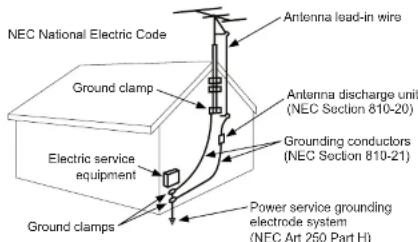
Note: Installation shall incorporate UL Listed external surge protection rated 2500 Vpk or less, for 150 to 300 Vac mains, installed in accordance with Article 285 of ANSI/NFPA 70 or applicable local codes.
Power Source
The display must be connected to a mains socket outlet with a protective grounding connection.
The mains plug is used as the disconnect device and shall remain readily accessible.
Electrical installation shall be in accordance with the applicable parts of Chapter 8 of ANSI/NFPA70.
An outdoor antenna should not be located near overhead electrical lines or any electrical circuits.
If an outside antenna is connected to the receiver, confirm that the antenna system is grounded to protect against voltage surges and built up static charges. Section 810 of the National Electric Code, ANSINFPA No 70-1984, provides information with respect to proper grounding for the mast and supporting structure, grounding of the lead-in wire to an antenna discharge unit, size of grounding connectors, location of antenna discharge unit; connection to grounding electrodes and requirements for the grounding electrode.
This display operates on 100-240 volts 50-60 Hz, AC current. Insert the power cord into a 220-240 volt 50 Hz outlet. Never connect the display to direct current or anything other than the specified voltage.
To prevent electric shock from the display, do not use with an extension cord, recentacle, or other
FCC CAUTION
To assure continued compliance and possible undesirable interference, ferrite cores may be used when connecting this display to video equipment; maintain at least 400mm (15.75 inches) spacing to other peripheral devices.
FCC STATEMENT
This equipment has been tested and found to comply with the limits for a Class A digital device, pursuant to Part 15 of the FCC Rule. These limits are designed to provide reasonable protection against harmful interference in a residential installation. This equipment generates, uses and can radiate radio frequency energy and, if not installed and used in accordance with these instructions, may cause harmful interference to radio communications; however, there is no guarantee that interference will not occur in a particular installation. If this equipment does cause harmful interference to radio or television reception, which can be determined by turning the equipment off and on, the user is encouraged to try to correct the interference by one or more of the following measures:
- Reorient or relocate the receiving antenna.
- Increase the separation between the equipment and receiver.
- Connect the equipment into an outlet on a circuit different from that to which the receiver is connected.
- Consult the dealer or an experienced radio/display technician for help.
This device complies with Part 15 of the FCC Rules. Operation is subject to the following two conditions:
• This device may not cause harmful interference.
- This device must accept any interference received, including interference that may cause undesired operation.
Relevant Information
Record your display's model and serial number here for future reference. Keep this user manual in an accessible location in the event service is required.
Note: Your display's serial number can be found on the box and underneath the rear cover plate.
Model Number
Serial Number
GENERAL SAFETY PRECAUTIONS
Read before operating equipment
Thank you for purchasing our product. Before using it, please read this user guide carefully and follow the instructions for safe operation. Please keep this manual for future reference and always include it when transferring or transporting this product to a different location.
▲ WARNING
In case of emergency such as fire or electric shock caused by the product, immediately contact 911 or proper emergency police/fire service agencies in your country.
- In case of product malfunction or unusual events such as electrical burning smell, smoke, or loss of content signals due to internal overheating, immediately turn off, unplug the electrical cord and contact the manufacturer.
- Do NOT disassemble, modify or service product in any way other than that contained in this instruction. Any unauthorized modifications made to the product automatically void product warranty.
- Do NOT touch antenna lines or wires, electrical cables or plugs when lightning or thunder is present or with wet hands
• Do NOT submerge in water. - Do NOT destroy, process, or place close to any heat source.
- Do NOT install near poisonous gas or chemically unstable atmosphere.
- Do NOT install near strong magnetic or electrical current field.
- Do NOT install the product in unstable locations or near moving objects, constantly vibrating equipment, or uneven surfaces.
- Do NOT leave any fire source, such as candles, close to or on the product.
- Do NOT operate the product if it has been dropped or struck. Severe physical impact to the product may cause components to fall out of place within and break.
- Do NOT bend or twist electrical cords, electrical plugs, cables, or wires with excessive force.
- Do NOT block ventilation slots or place any heavy object on the product.
• Use properly rated electrical voltage. - Do NOT use any electrical sockets or power strips with many other devices jointly plugged in. Use a single, directly dedicated and rated GFCI electrical outlet for the product for safe operation.
- Do NOT move or transport with any cables (electrical, content connectivity) plugged in to the source devices.
- Always connect the electrical plug firmly and completely. When disconnecting any cables, always pull on the plug and not the cord.
• Always leave the power off when plugging or unplugging the electrical cords or connection cables. - Do not defeat the safety purpose of the polarized or grounding type electrical plug. A polarized plug has two blades with one wider than the other. A grounding type plug has two blades and a third grounding prong. The wide blade or the third prong are provided for your safety. If the provided plug does not fit into your outlet, consult an electrician for replacement of the obsolete outlet.
▲ WARNING
- Never apply pressure to the exterior of the LCD screen.
- If monitor or glass is broken, do not come in contact with the liquid crystal and handle with care.
- Do NOT climb on the product.
- Do NOT install within five feet from a body of water.
- Do NOT use if ambient air temperature exceeds the operating limits.
- Do NOT install in enclosure or recessed cavity with less than 2 inches of airflow around the display. Air inside fully encased display must be ventilated.
• The product is to be secured to building before operation. - Product must be carried and supported by at least two persons.
• Periodically clean dust off the electrical plug to keep it clean and dry, ensuring proper and safe operation. - Only use attachments/accessories specified by the manufacturer.
CONTENTS
System Installation And Electrical Requirements 2
Electrical Code 2
Power Source 2
FCC Caution....3
FCC Statement....3
General Safety Precautions 4
Set Up Instructions....7
Parts List 7
Removing Cord Cover....8
Installing Power Cord 9
Installing IR Extender 9
Installing ALS Extender 9
Connecting Cords....10
Replacing Cord Cover 12
Replacing Handle Hardware 13
Connect To The Power Source....13
Prepare The Display For Mounting 14
Remote Control Battery Installation And Replacement....16
Operating Instructions 17
Power On/Off the Display 17
Onboard Controls....17
Navigating The On-Screen Menu 18
Picture 18
Audio 18
Time 19
Setup 19
Lock 20
USB Functionality 22
(RS-232C) Serial Control Of The Display 24
Maintenance 25
Care Of The Screen 25
Mobile Telephone Caution 25
End Of Life Directives 25
Product Specifications 26
Display....26
Power 26
Display Controller Features 26
Environmental 26
SET UP INSTRUCTIONS
| Parts List | ||||
| Description Qty | XHB432-EUK Part # | XHB492-EUK Part # | XHB552-EUK Part # | |
| A display 1 180-W1678-3 180-W1679-3 180-W1680-3 | ||||
| B remote 1 410-0049 410-0049 410-0049 | ||||
| C 4mm allen wrench 1 560-9646 560-9646 560-9646 | ||||
| D M6 x 12mm 4 580-D1734 580-D1734 580-D1734 | ||||
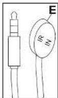
| E IR extender 1 600-0711 600-0711 600-0711 | ||||
| F AU power cord | 1 410-1205 410-1205 410-1205 | |||
| G EU power cord | 1 | 410-1198 | 410-0198 | |
| H UK power cord | 1 | 410-1199 | 410-0199 | |
| I user guide (not shown) | 1 | 180-9120 | 180-9120 | |
| J remote guide (not shown) | 1 | 180-9098 | 180-9098 | |
| K monitoring addendum (not shown) | 1 190-9020 180-9020 180-9020 | |||
| L technical support insert (not shown) | 1 983-0721 983-0721 983-0721 | |||
| M accessory insert (not shown) | 1 | 983-0738 | 983-0738 | |

natural_image
Technical diagram of a device with labeled section A(1) and display components (no text or symbols beyond label)B (1)

C (1)
4mm allen wrench

D (4)
M6 x 12mm

F (1)
power cord
(AU)

H (1)
power cord

G (1)
power cord

E (1)
R extender


Removing Cord Cover
- Remove (2) M6 low-profile hex screws and rear cover plate using 4mm allen wrench (C). Do not
disconnect lanyard. - Remove (6) M5 hex screws and cord cover using 4mm allen wrench (C).

Installing Power Cord
Insert female end of power cord (F,G,H) into power port located inside the input compartment.

Installing IR Extender (Optional)
Insert the 3.5mm end of the included 5V IR extender into the IR Extender port on the input panel of the display. IR extender port may not be compatible with other 3 ^rd party extenders.
Installing Ambient Light Sensor (ALS) Extender (Optional)
Insert the 3.5mm end of the ALS Extender (ACCD-ALS sold separately) into the ALS Extender port on the input panel of the display. Connecting the ALS Extender will disable the ALS that is built into the display.

Connecting Cords
Connect source devices to appropriate display input. Make all connections prior to powering on the display. The USB 2.0 Data port is for service and media only. For 5VDC power, use the 5VDC power port.

- 2.5mm DC Power Port – Provides 12 VDC @ 2.5 A for powering locally stored extenders and source devices. 12 VDC accessory kits (ACCD-12K) are sold separately from Peerless-AV by contacting Customer Care at +44 (0) 1923 200 100. Accessory DC outputs are only active when display is on.
- USB DC Power Port – Provides 5 VDC @ 2.4 A for powering locally stored extenders and source devices. 5 VDC accessory kits (ACCD-05K) are sold separately from Peerless-AV by contacting Customer Care at +44 (0) 1923 200 100.
- RS232C DB9 Port – Allows for control of the display using RS232 commands from a connected PC or control system. Pin Out: Pin 2 (RX), Pin 3 (TX), Pin 5 (GROUND)
- 3.5mm IR Extender Port – Allows flexibility for integration with controls systems. The IR extender can be used to position the IR receiver in a convenient position in the event the IR receiver on the front of the display is obscured.
- 3.5mm Analog Audio Out Port – Provides analog stereo audio for soundbars, headphones, and amplifiers.
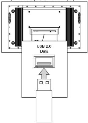
- USB 2.0 Data Port – Allows content to be displayed using a USB flash drive. This feature supports text, photo, audio and video. This port also serves as a service port for firmware upgrades. This port should not be used for powering 5 VDC devices.
- DisplayPort – Connects a digital source device with the display and allows for FHD video and digital audio to be output on the display. DisplayPort is version 1.2 and is HDCP 1.3 compliant.
- HDMI 1 (ARC) - Connects a digital source device with the display and allows for FHD video and digital audio signal to be output to the display. HDMI 1 is HDMI version 2.0 and is HDCP 2.2 compliant. All 3 of the HDMI inputs also support consumer electronics control (CEC). CEC allows for intelligent communication between CEC-enabled devices through the use of the HDMI connection. HDMI 1 also supports the audio return channel (ARC) allowing audio content from the display to be back-fed to an audio amplifier using a single HDMI connection.
- HDMI 2 - Connects a digital source device with the display and allows for FHD video and digital audio signal to be output to the display. HDMI 2 is HDMI version 2.0 and is HDCP 2.2 compliant. All 3 of the HDMI inputs also support consumer electronics control (CEC). CEC allows for intelligent communication between CEC-enabled devices through the use of the HDMI connection.
Connecting Cords
- VGA – Connects an analog source device with the display and allows FHD video signals to be output to the display. VGA does not support audio. When using a VGA connection the audio output from the source device will need to be connected to the 3.5mm Audio In port on the display.
- 3.5mm Analog Audio In – Accepts the incoming stereo analog audio signal coming from a VGA connected source device.
- S/PDIF Optical Output – Outputs uncompressed digital audio to a connected soundbar or AVR with an optical digital audio input.
- 3.5mm Mini AV – Connects an analog source device with the display and allows for SD video and analog stereo audio signals to be output to the display. This connection also supports the audio portion of a connected component device. Requires a 3.5mm to RCA female composite accessory dongle. Analog accessory kits (ACCD-ALG) are sold separately from Peerless-AV by contacting Customer Care at +44 (0) 1923 200 100.
- 3.5mm Mini Component – Connects an analog source device with the display and allows for HD video and analog stereo audio signals to be output to the display. Requires a 3.5mm to RCA female component accessory dongle for video signals. If audio is required when using the component connection, the stereo audio signal will need to connect to the red and white female RCA connectors on the composite accessory dongle. Analog accessory kits (ACCD-ALG) are sold separately from Peerless-AV by contacting Customer Care at 444 (0) 1923 200 100.
- LAN Port – Supports Network Control via TCP/IP (refer to Network Command section). Future Use: Health and Wellness monitoring of the display (see Monitoring Adendum).
- 3.5mm Ambient Light Sensor (ALS) Extender – Automatically adjusts the brightness of the display based on ambient lighting conditions. The ALS extender overrides the built-in ambient light sensor when it is connected allowing flexibility for installations where the built-in ALS may have shadows being cast on it by surrounding structures or vegetation. The ALS extender can be placed in a location that is more representative of the actual ambient light conditions. ALS Extenders (ACCD-ALS) are sold separately from Peerless-AV by contacting Customer Care at +44 (0) 1923 200 100.
Replacing Cord Cover
- Run power and signal cords through notches. To prevent unwanted interference, route the power cord through the left most notch (see image 1 below).
- Place the cord cover over the cords being careful not to pinch any of the cords. Loosely install (6) M5 hex cap screws then tighten screws on the cord cover using 4mm allen wrench (C) until the gasket on the cover is fully compressed to the cord gasket.
- Replace the rear cover plate ensuring that the cords are running through the notches on the display and not getting pinched. Fasten the (2) hex screws on the rear cover plate to secure it in place using 4mm allen wrench (C). Ensure that rear cover plate is fully compressed to the back of the display.


natural_image
Technical line drawing of a mechanical assembly with no visible text or symbolsCAUTION
Failure to follow these instructions can result in the product being damaged or destroyed, voiding the warranty.
CAUTION


Replacing Handle Hardware
Optional: If removing handles, replace with hardware provided.

Connect To The Power Source
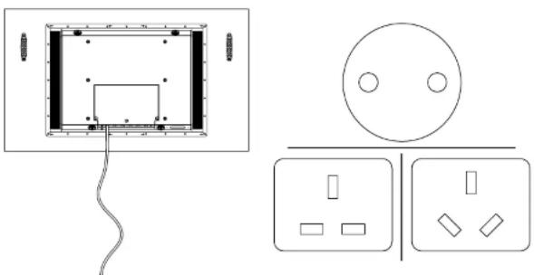
Connect power cord to GFCI outlet.
natural_image
Pure electrical circuit lines without any symbolsPrepare The Display For Mounting
Install cords prior to mounting your display. Input panel may be obstructed once the display is mounted.
A mounting solution is sold separately. Contact your Peerless-AV representative for an outdoor rated mounting solution for your particular application.
For your safety, only install an outdoor-rated mount that is suitable for the application and supports the weight of the display. When mounting a display outdoors, use proper environmentally rated mounts to ensure longevity in harsh environments.
Examine the chart below to determine the mounting specifications for your display:
| Model | Mounting Hole Pattern | Required Mounting Screws |
| XHB432-EUK | 400x200mm | (4) M8 screws |
| XHB492-EUK | 400x400mm | (25mm long) |
| Model A B | C D E F | |||||
| XHB432-EUK | 15.75" (400mm) | 15.75" (400mm) | 11.87" (302mm) | 3.77" (96mm) | 4.89" (124mm) | 7.87" (200mm) |
| XHB492-EUK | 15.75" (400mm) | 15.75" (400mm) | 14.49" (368mm) | 5.24" (133mm) | 3.92" (100mm) | 7.87" (200mm) |
| XHB552-EUK | 15.75" (400mm) | 15.75" (400mm) | 17.16" (436mm) | 6.74" (171mm) | 3.92" (100mm) | 7.87" (200mm) |

Prepare The Display For Mounting
| Model A B | C D E F | |||||
| XHB432-EUK | 39.50" (1003mm) | 23.28" (591mm) | 37.06" (941mm) | 20.84" (529mm) | 42.51" (1080mm) | 0.33" (8mm) |
| XHB492-EUK | 44.72" (1136mm) | 26.22" (666mm) | 42.27" (1074mm) | 23.78" (504mm) | 48.50" (1232mm) | 0.33" (8mm) |
| XHB552-EUK | 50.07" (1272mm) | 29.23" (742mm) | 47.62" (1210mm) | 26.79" (580mm) | 54.64" (1388mm) | 0.42" (11mm) |


Remote Control Battery Installation And Replacement
The remote control is powered by two 1.5V AAA batteries installed at the factory.
To install or replace batteries:
- To remove the battery module of the remote control, remove the two screws on the end of the battery module. Slide the battery module out of the remote control.
- Insert two new 'AAA' size batteries into the battery module.
- Slide the battery module back into the remote control and reinsert the two screws in the end of the battery module.
▲ CAUTION
Incorrect usage of batteries can result in leaks or bursting. Peerless-AV recommends the following battery use:
- Do not mix battery brands.
- Do not combine new and old batteries. This can shorten the battery life or cause battery acid leaks.
- Remove dead batteries immediately to prevent battery acid from leaking into the battery compartment.
- Do not touch exposed battery acid as it may injure skin.
- Remove the batteries if you do not intend to use the remote control for a long period of time.
- Do not expose the batteries to excessive heat from sunlight, fire or other heat sources or batteries could explode.
- Fully tighten screws to maintain the ingress protection rating of the remote.

OPERATING INSTRUCTIONS
Power On/Off The Display
Power on your display by using the remote control or the power button on the bottom, left-hand side of the display. The display will power on but image may not appear for several seconds as it completes its power up sequence.
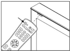
Point the remote control at the IR sensor located at the top, left-hand corner of the display when in landscape, or the top right-hand corner when in portrait, then press the power button.
natural_image
Line drawing of a remote control with a pointer and scroll, no text or symbols present| LED Light | TV Status |
| Solid | Off |
| Blinking | Boot up |
| Off On |
Onboard Controls
Direct Mode: Allows for quick access to source selection, volume settings and channel selection. Menu Mode: Press the Menu button to access Menu Mode and activate the On Screen Display (OSD). For a description of OSD operation refer to the next section.
The keypad buttons are assigned as indicated in the table below.
| Direct Mode Menu Mode | |
| Channel Up Up | |
| Channel Down Down | |
| Menu Return | |
| Volume Up Right/OK | |
| Volume Down Left/OK | |
Navigating The On Screen Menu


Audio
| Equalizer Standard | |
| Music | |
| Movie | |
| Sports | |
| Personal | |
| Digital Output (Optical) | PCM / Raw / Off |
| Surround On / Off | |
| Audio Only On / Off | |
| AVC On / Off | |

| Time | |
| Sleep Timer off | 60 min |
| 5 min | 90 min |
| 10 min | 120 min |
| 15 min | 180 min |
| 30 min | 240 min |
| Time Zone Atlantic | Pacific |
| Eastern | Alaska |
| Central | Hawaii |
| Mountain | Korean |
| Time Format 12-hour | |
| 24-hour | |
| Auto Sync On / Off | |
| Clock Enter Current Time | |
| Wake Up Enter desired time when display will turn on | |
Navigating The On Screen Menu
| Setup | ||
| Menu Languages | English Spanish French | Italian German Russian |
| Transparent (Menu Transparency) | 0%25%50%75%100% | |
| Restore Defaults Factory reset all options | ||
| Setup Wizard | ||
| Software Update Yes / No | ||
| CEC | ||
| CEC Control On / Off | ||
| Device Auto Power Off | On / Off | |
| TV Auto Power On | On / Off | |
| Audio Receiver On / Off | ||
| Device Lists Lists connected CEC devices | ||
| Connect (future use) | ||
| Root Menu Menu of connected source device | ||
| No Signal Auto Power Off | On / Off / Backlight | |
| Lock | |
| System LockEnter Password to enter System Lock settingsDefault Password: 0000 | |
| Change password | Allows the password to be changed |
| System Lock | On / Off |
| Input Block | AV, Component, DP, HDMI 1, HDMI 2, HDMI 3, PC, USB |
| Hotel ModeEnter password to enter hotel mode settingsDefault Password: 0000 | |
| Hotel Mode | On / Off |
| Change Password | Allows the password to be changed |
| Picture Mode | Standard, Dynamic, Theater, Personal |
| Sound Mode | Standard, Music, Movie, Sports, Personal |
| Key Lock | On / Off |
| Power On Source | AV, Component, DP, HDMI 1, HDMI 2, HDMI 3, PC, USB |
| Power On Volume | Set volume that display will output when turned on |
USB Functionality
1
ENG Insert USB flash drive into USB 2.0 Data port on the input panel of the display.
2
ENG Select USB source to access content.
| Input Source |
| AV |
| Component |
| DP |
| HDMI1 |
| HDMI2 |
| HDMI3 |
| PC |
| USB← |
USB Functionality
3
ENG Select media type and folder where content is stored.

PHOTO

MUSIC MOVIE TEXT


Return C

1. 2017年
4

Photos – To view a single photo, select photo and press play. To view a slide show, select multiple photos and press play. Use on screen menu to control slide show.

Movies – To view a single video, select video and press play. To view a playlist, select multiple videos and press play. Use on screen menu to control playlist.

Music – To listen to a single song, select song and press play. To listen to a playlist, select multiple songs and press play. Use on screen menu to control playlist.

Text – To view to a single text file, select file and press play. To view a playlist, select multiple files and press play. Use on screen menu to control playlist.



(RS-232C) Serial Control Of The Display
Attach an RS-232C cable (straight through type) to the supplied D-Sub RS-232C to utilize serial control function. Control via RS232 should only be utilized by experts familiar with RS232 progra
| Menu: | A0, F0, 55, FF, 4E, B1 | Mute: | A0, F0, 55, FF, 14, EB |
| Right: | A0, F0, 55, FF, 05, FA | Sleep: | A0, F0, 55, FF, 53, AC |
| OK: | A0, F0, 55, FF, 02, FD | AV: | A0, F0, 55, FF, ED, 12 |
| Down: | A0, F0, 55, FF, 0D, F2 | VGA: | A0, F0, 55, FF, EA, 15 |
| Up: | A0, F0, 55, FF, 17, E8 | HDMI Toggle: | A0, F0, 55, FF, EC, 13 |
| Left: | A0, F0, 55, FF, 0C, F3 | HDMI1: | A0, F0, 55, FF, DE, 21 |
| Source: | A0, F0, 55, FF, 01, FE | HDMI2: | A0, F0, 55, FF, DF, 20 |
| (1): | A0, F0, 55, FF, 42, BD | HDMI3: | A0, F0, 55, FF, E0, 1F |
| (2): | A0, F0, 55, FF, 43, BC | DisplayPort: | A0, F0, 55, FF, E4, 1B |
| (3): | A0, F0, 55, FF, 0F, F0 | Component: | A0, F0, 55, FF, E7, 18 |
| (4): | A0, F0, 55, FF, 1E, E1 | USB: | A0, F0, 55, FF, 57, A8 |
| (5): | A0, F0, 55, FF, 1D, E2 | PMODE: | A0, F0, 55, FF, 4B, B4 |
| (6): | A0, F0, 55, FF, 1C, E3 | Zoom: | A0, F0, 55, FF, 51, AE |
| (7): | A0, F0, 55, FF, 18, E7 | SMODE: | A0, F0, 55, FF, 5B, A4 |
| (8): | A0, F0, 55, FF, 45, BA | VOL 0%: | A0, F0, 55, FF, 20, DF |
| (9): | A0, F0, 55, FF, 4C, B3 | VOL 25%: | A0, F0, 55, FF, 21, DE |
| (10): | A0, F0, 55, FF, 56, A9 | VOL 50%: | A0, F0, 55, FF, 22, DD |
| Exit: | A0, F0, 55, FF, 1B, E4 | VOL 75%: | A0, F0, 55, FF, 23, DC |
| Power On: | A0, F0, 55, FF, AE, 51 | VOL 100%: | A0, F0, 55, FF, 24, DB |
| Power Off: | A0, F0, 55, FF, AD, 52 | Brightness 0%: | A0, F0, 55, FF, 25, DA |
| Power On/Off: | A0, F0, 55, FF, 0B, F4 | Brightness 25%: | A0, F0, 55, FF, 26, D9 |
| Volume +: | A0, F0, 55, FF, 0A, F5 | Brightness 50%: | A0, F0, 55, FF, 27, D8 |
| Volume -: | A0, F0, 55, FF, 40, BF | Brightness 75%: | A0, F0, 55, FF, 28, D7 |
| Surround: | A0, F0, 55, FF, C7, 38 | Brightness 100%: | A0, F0, 55, FF, 29, D6 |
| Info: | A0, F0, 55, FF, 50, AF | Dash: | A0, F0, 55, FF, 2E, D1 |
COM Settings
| Baud Rate 38400 |
| Data Bits 8 |
| Parity None |
| Stop Bits 1 |
Network Commands Of The Display
Attach an ethernet cable (straight through type) to the ethernet port to utilize network command function. Control via TCP/IP should only be utilized by experts familiar with TCP/IP programming.
| Menu: | 0252433030304D454E03 | DP: | 0252433030302D445003 |
| Left: | 0252433030304C454603 | VGA: | 02524330303056474103 |
| Right: | 02524330303052494703 | USB: | 02524330303055534203 |
| Up: | 0252433030302D555003 | Volume 0%: | 02524330303056303003 |
| Down: | 025243303030444F5703 | Brightness 0%: | 02524330303042303003 |
| OK: | 0252433030302D4F4303 | Onekey Sw Info: | 0252433030304F4B4903 |
| Exit: | 02524330303045584903 | Onekey Aging: | 0252433030304F4B4103 |
| Power On: | 0252433030302D4F4E03 | Key Lock On: | 0252433030304B4C4E03 |
| Power Off: | 0252433030304F464803 | Kay Lock Off: | 0252433030304B4C4603 |
| Volume +: | 025243303030564F2B03 | 12V Toggle On: | 02524330303050313103 |
| Volume -: | 025243303030564F2D03 | 12V Toggle Off: | 02524330303050313003 |
| Mute: | 0252433030304D555403 | 5V Toggle On: | 02524330303050323103 |
| Source: | 025243303030534F5503 | 5V Toggle Off: | 02524330303050323003 |
| HDMI 1: | 02524330303048443103 | ||
| HDMI 2: | 02524330303048443203 | ||
| HDMI 3: | 02524330303048443303 |
MAINTENANCE
Care Of The Screen
Do not rub or strike the screen with anything hard as this may scratch, mark, or even damage the screen permanently. Ensure that the display is installed in a location where it will be safe from abrasives and flying debris, which could damage the LCD panel. Never use ammonia or any product containing ammonia, as it will damage the anti-glare coating on the face of the display. Only use an approved screen cleaner to clean the display face. Unplug the power cord before cleaning the screen. Dust the display by wiping the screen and the cabinet with a soft, clean cloth. If the screen requires additional cleaning, use a clean, damp cloth. Do not use aerosol cleaners, or solvents of any kind. Do not use any chemical such as paint thinner or benzene to clean the product's exterior. It may cause scratches on the surface, erasing proper indications, identification labels, or instructions on the exterior, which may cause misuse and improper operation of the product.
Mobile Telephone Caution
Keep your mobile telephone away from your display to avoid disturbances in the picture or sound, possibly causing permanent damage to your display.
End Of Life Directives
In an effort to produce environmentally friendly products, your new display contains materials that can be recycled and reused. At the end of your display's life, specialized companies can minimize display waste by separating reusable materials from non-reusable materials. Please ensure you dispose of your display according to local regulations.
PRODUCT SPECIFICATIONS
Specifications subject to change without notice.
| Display | |
| Screen Size (diagonal) | XHB432-EUK: 43" XHB492-EUK: 49" XHB552-EUK: 55" |
| Aspect Ratio | 6:9 |
| Resolution | 1920 x 1080 |
| Brightness | 2.500 cd/m ^2 |
| Contrast Ratio | 300:1 |
| Viewing Angle | 78° vertical / horizontal |
| Response Time (gray to gray) | XHB432-EUK: 12ms XHB492-EUK: 8ms XHB552-EUK: 12ms |
| Refresh Rate | 60 Hz |
| Power | |
| AC Input | 100 VAC to 240 VAC,50 to 60 Hz |
| Environmental | |
| Operating Temperature | -31°F to 118°F(-35°C to 48°C) |
| Storage Temperature | -4°F to 140°F(-20°C to 60°C) |
| IP Rating | P68 |
| Safety/EMC | FCC Class A |
| Display Controller Features | |
| Display System | NTSC |
| Picture Adjustment | Brightness, Contrast, Tint, Sharpness, Color |
| Picture Mode | Standard, Dynamic, Theater, Personal |
| Color Temperature Adjustment | Cool, Normal, Warm, Personal |
| Screen Adjustment | 16:9, Full, Zoom, 4:3, Point to Point |
| ECO | Low, Middle, High, Personal, Auto |
| Clock, Sleep Timer | Yes |
| Mute | Yes |
| OSD Language | English, Spanish, French, German, Italian, Russian |
| Backlight Adjustment | Manual and Automatic Control |
| Mechanical | |
| Display Size: | (W × H × D) |
| XHB432-EUK | 39.5" x 23.28" x 4.89"(1003 x 591 x 124mm) |
| XHB492-EUK | 44.72" x 26.22" x 3.92"(1136 x 666 x 100mm) |
| XHB552-EUK | 50.07" x 29.23" x 3.92"(1272 x 742 x 100mm) |
| Enclosure Color Block | |
| VESA Mount 400x200mm, 400x400mm | |
| Net Weight | |
| XHB432-EUK | 88 lbs. (39.91kg) |
| XHB492-EUK | 92 lbs. (41.70kg) |
| XHB552-EUK | 133 lbs. (60.00kg) |
| Shipping Size | (W × H × D) |
| XHB432-EUK | 45.5" x 28.25" x 10.63"(1156 x 718 x 270mm) |
| XHB492-EUK | 50.25" x 30.75" x 10.63"(1276 x 781 x 270mm) |
| XHB552-EUK | 55.625" x 34.125" x 10.63"(1413 x 867 x 270mm) |
| Shipping Weight: | |
| XHB432-EUK | 98 lbs. (44.45kg) |
| XHB492-EUK | 103 lbs. (46.72kg) |
| XHB552-EUK | 145 lbs. (65.77kg) |
| Glass IK10 Rated, Tempered & Anti-reflective | |
| Input/Output Connections | |
| VGA Input | 5 pin D-SUB (x1), up to 1920x1080@60Hz |
| HDMI Input | HDMI (x3), 480i, 480p, 576i, 576p, 720p, 1080i, 1080p |
| DisplayPort | DisplayPort (x1), 480i, 480p, 576i, 576p, 720p, 1080i, 1080p |
| CVBS Input | 3.5mm (x1), 480i, 576i |
| YPbPr Input | 3.5mm (x1), 480i, 480p, 576i, 576p, 720p, 1080i |
| VGA Stereo Audio Input | 3.5mm Analog Audio (x1) |
| Audio Output | 3.5mm Stereo Headphone (x1) |
| RS232 Control | 9 pin D-SUB (Female) (x1) |
| TosLink Digital Audio Output | Optical (x1) |
| IR Extender | 3.5mm (x1) |
| USB 2.0 Data | USB A (Female) (x1) |
| 5VDC 2.4A Output(USB Power) | USB A (Female) (x1) |
| 12VDC 2.5A Output | Barrel 2.5mm (ID)5.5mm (OD) (x1) |
| LAN Input | RJ45 (x1) |
| ALS Extender | 3.5mm (x1) |
LIMITED TWO-YEAR WARRANTY
TWO-YEAR PARTS & LABOR LIMITED WARRANTY
Terms of Peerless-AV50
The Peerless-AV Outdoor TV/Display is warranted to be free of defects in material and workmanship from the time of purchases by the original owner. If this product is proven to be defective under the terms and conditions of this warranty, Peerless-AV will repair or replace defective parts with new and/or reconditioned parts at no charge for the parts and labor to the original owner, subject to the terms and conditions of this Limited Warranty. This Limited Warranty covers failures due to defects in material or workmanship that occur during normal use as follows:
- Paris – the warranty period for parts is: two (2) years from the date of original purchase. During the applicable Limited Warranty period for parts, defective parts will be replaced at no charge. Parts used for the repair will be warranted for the remainder of the original warranty period for those parts.
- Labor – the warranty period for labor is: two (2) years from the date of original purchase. During the applicable Limited Warranty period for labor, Peerless-AV will provide the labor for warranty repair at no change for a period of less (2) years from the date of original purchase.
• Original owner must provide verification of the date of purchase when requesting Limited Warranty Services. A copy of the original Dated Sales Receipt is required together with the product serial number to obtain service under this Limited Warranty.
- All experts must be performed by a Perekeko-AV Authorized Service Provider.
- Customer is responsible for returning (including any freight and shipping cost) defective unit to Peerless-AV Authorized Service Provider. If the product is found to have no defects, the customer will be responsible for return shipping costs as well the diagnostic bench fee. If the product is found to be covered by the manufacturer's warranty, Peerless will assume responsibility for return freight charges.
THIS LIMITED WARRANTY DOES NOT COVER
• Labor la urinald
- Shipping damage. - Damage caused during customer unpacking, and/or removal of protective packaging materials.
- Damage due to improper, incorrect or insufficient AC voltage power surges or lightning strikes.
- Damage due to inadequate signal group, incorporation into other products or repairs by anyone other than a Peerless-AV Technician.
- Damage due to lampening or removal of any gasket material. Including but not limited to the cable gland gaskets within the cable pulls were
- Damage which results from fire, flood, lightning, tornado, hurricanes, lungs had, extremely gusty winds, sand slums, vandalism, terrorism or other acts of nature.
- Any and which has been modified or damaged due to improper installation or failure to obey the operating instructions provided in the User Manual.
• Any failure, loss, damage or personal injury due to accident, neglect, misuse, abuse, improper operation, improper storage, alteration to the unit, or failure by the consumer to follow operating instructions provided in the User Manual.
- Any und purchased from anergalbated selic
- If the original product serial number has been removed.
delaxed or tampered with in any way
• Any packaging or transportation charges incurred in
• Indirect consequential, or special damages except as
- Failure due to installation in sensors with insufficient heat
dissipation and/or ventilation
- The LCD is a Class 2 ISO panel. As such, the Pixel Fault for
Typ 1 = Hot Point (always on - white).
- Type 2 = Does Point (always on - black); or
- In a Black-Black (1) and other non-parkets (4)
- The initial number of permitted details per 2 million
piscely
Type 1 = (4)
Type 2 = (4)
Type 3 = 10E
• Picture quality when installed in direct sunlight where sun is shown directly on the face of the LCD
- Any damage, scratches or blemishes to the face of the LCD
and/or exterior cabinet due to end-user cleaning.
- Dirty air waves, and/or unusual signal interference due to
satisfite service providers, or unusual signal interference
• Any campaign resulted through improper pregnancy. If the
Outdoor TV Display needs to be returned. Original packaging
Вс тимулян. (1) Вс ср.Кола, 1765 г. 2013; 1766 м. 211000 г. Котрибов
15 contact a Poorices-IV Care Customer Representative to
request a new hor to be delivered to customer shipping site)
- Reelit shipping when he detect it hand.
For Non-Warranted Repairs, or for claims found to not be covered by the Limited Warranty, the customer will be responsible for the diagnostic breach fee, the cost of replacement parts, and any applicable shipping charges. Repaired Non-Warranted claims require payment in full before repaired products are returned to customers.
Poorless-AV and its representatives or agents shall in no event be liable for any general, indirect or consequential damages arising out other caused by the use of/or inability to use this product.
The Warranty is made in lieu of all other warranties, expressed or
implied, and all other liabilities on the part of Peerless-AV. Any other warranties, including warranties of merchantability and fitness for a particular purpose are hereby disclaimed by Peerless-AV and its representatives and/or aspects.
The laws of some states do not allow exclusion of implied warranties; therefore, this warranty shall be deemed modified to be consistent with such laws. This limited Warranty gives you specific legal rights. You may also have other rights that vary from state to state.
All warranty inspections and repairs must be performed by Peerless
AV or its authorized service representatives.
Please call +44 (0) 1923 200 100 so that the Peerless-AV technical support team not valid with proper train/stechooting steps. Please have your receipt and rental number variable during the time of call while onsite. Technical support will determine whether the product will need to be replaced or returned for repair. If a receipt is needed, Customer Care will issue a Return Material Authorization (IDA) number. The product will need to be in the original packaging and handed to a said in the upright position. If the product is not covered by the warranty, Peerless-AV will contact you with repair estimates after inspection.
goodness AV®



- SYSTEM INSTALLATION AND ELECTRICAL REQUIREMENTS
- Electrical Code
- Power Source
- FCC CAUTION
- FCC STATEMENT
- Relevant Information
- GENERAL SAFETY PRECAUTIONS
- Read before operating equipment
- ▲ WARNING
- CONTENTS
- Removing Cord Cover
- Installing Power Cord
- Installing IR Extender (Optional)
- Installing Ambient Light Sensor (ALS) Extender (Optional)
- Connecting Cords
- Replacing Cord Cover
- CAUTION
- Prepare The Display For Mounting
- Remote Control Battery Installation And Replacement
- ▲ CAUTION
- OPERATING INSTRUCTIONS
- Power On/Off The Display
- Onboard Controls
- USB Functionality
- 1
- 2
- 3
- 4
- MAINTENANCE
- Care Of The Screen
- Mobile Telephone Caution
- End Of Life Directives
- LIMITED TWO-YEAR WARRANTY
Brand : Peerless-AV
Model : XHB492-EUK
Category : Monitor