SPC5050 - Uncategorized Stinger - Free user manual and instructions
Find the device manual for free SPC5050 Stinger in PDF.


| Product Type | Car Audio Amplifier |
| Model | SPC5050 |
| Brand | Stinger |
| Dimensions (W x H x D) | 10.5 x 2.2 x 6.3 inches |
| Weight | 3.5 lbs |
| Power Supply | 12V DC (negative ground) |
| Max Power Output | 500 watts |
| RMS Power Output (2 ohm) | 250 watts per channel |
| RMS Power Output (4 ohm) | 150 watts per channel |
| Channel Configuration | 2-channel (stereo) with bridgeable output |
| Frequency Response | 20 Hz - 20 kHz |
| Input Sensitivity | 200 mV - 4 V |
| Signal-to-Noise Ratio | 95 dB |
| Total Harmonic Distortion | < 0.05% |
| Low-pass Filter | 40 Hz - 400 Hz (variable) |
| High-pass Filter | 40 Hz - 400 Hz (variable) |
| Bass Boost | 0 - 12 dB (variable at 45 Hz) |
| Protection Features | Thermal, short circuit, overvoltage, undervoltage |
| Recommended Fuse | 30A (inline) |
| Terminal Size | 4 AWG power/ground, 16 AWG speaker |
| Maintenance | Clean with soft dry cloth; ensure vents are unobstructed |
| Safety Warnings | Disconnect battery before installation; do not expose to moisture |
| Spare Parts & Repairability | No user-serviceable parts; contact qualified technician |
Frequently Asked Questions - SPC5050 Stinger
User questions about SPC5050 Stinger
0 question about this device. Answer the ones you know or ask your own.
Ask a new question about this device
Download the instructions for your Uncategorized in PDF format for free! Find your manual SPC5050 - Stinger and take your electronic device back in hand. On this page are published all the documents necessary for the use of your device. SPC5050 by Stinger.
USER MANUAL SPC5050 Stinger
Stinger® offers everything you need.
to make your sound system
perform at it's best!
EXPERT LEVEL PRODUCTS
INTERCONNECTS
POWER WIRE
SPEAKER WIRE
WIRING KITS
HPM DIGITAL CAPACITORS
PRO DIGITAL CAPACITORS
CAPACITORS
BATTERIES
ALTERNATORS
BATTERY TERMINALS
TERMINALS
FUSE HOLDERS
POWER DISTRIBUTION
CARPET, CLOTH, & VINY
ELECTRONICS
SWINGERWEAR
Stinger ^®
13160 56 ^th Court
Clearwater, FL 33760
727-572-9255
stingerelectronics.com
©2009 AAMP of Florida™, Inc.


HYBRID
POWER
CAPACITOR
SPECIFICATIONS
Model # SPC5050
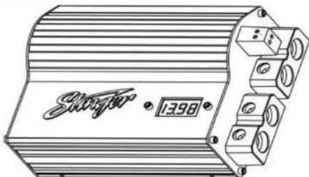
50 Farad Hybrid Super Capacitor with RED Digital Voltage Meter
Capacitance.... 50.000.000 micro farad (50 Farad)
Working Voltage.... 16 DCV
Surge voltage.... 18 DCV E.S.R. (Equivalent Series Resistance).....0.0015 ohm @ 120hz/ 25°C
Capacitance Tolerance....± 10 %
Model # SPC5010
10 Farad Hybrid Super Capacitor with RED Digital Voltage Meter
Capacitance.... 10.000.000 micro farad (10 Farad)
Working Voltage.... 16 DCV
Surge Voltage....18 DCV
E.S.R. (Equivalent Series Resistance).....0.0015 ohm @ 120hz/ 25°C
Capacitance Tolerance....± 10 %
Model # SPC505
5 Farad Hybrid Super Capacitor with RED Digital Voltage Meter
Capacitance.... 5.000.000 micro farad (5 Farad)
Working Voltage.... 16 DCV
Surge Voltage....18 DCV
E. S. R. (Equivalent Series Resistance)... 0.0015 ohm @ 120hz/25°C
Capacitance Tolerance....± 10 %
WARRANTY STATEMENT
Stinger® Hybrid Capacitors are nearly indestructible and will provide years of reliable service if installed and used according to the instructions in this manual. Stinger® ("Company") warrants to the original retail purchaser of this product that should the product or any part thereof be proven defective in material or workmanship within a period of 1 year from date of purchase by original purchaser; such defects will be repaired or replaced, at the Company's option, without charge for parts or labor.
If you believe you have a defective capacitor, contact Stinger® technical support (727-572-9255 ext. 230) to discuss your problem. If it is agreed that the capacitor is defective, the product should be delivered, transportation prepaid to the Authorized Stinger® Dealer it was purchased from for repair or replacement. If you are unable to contact your Authorized Stinger® Dealer, you may contact Stinger® customer service at 727-572-9255 ext. 249 for return authorization instructions.
Items specifically not covered include but are not limited to the following: • Stripped terminals.
• Broken terminal bolts or studs.
- Blown vent plugs as a result of reverse polarity or over-voltage.
•Physical Damage or Improper Installation
THIS WARRANTY DOES NOT APPLY TO ANY PRODUCT OR PART THEREOF WHICH HAS BEEN DAMAGED THROUGH ALTERATION, MISHANDLING, MISUSE, NEGLECT, ACCIDENT, IMPROPER INSTALLATION OR UNAUTHORIZED REPAIR.
THIS WARRANTY IS EXCLUSIVE AND IN LIEU OF ANY AND ALL OTHER WARRANTIES, EXPRESSED OR IMPLIED, INCLUDING WITHOUT LIMITATION THE IMPLIED WARRANTIES OR MERCHANTABILITY AND FITNESS FOR A PARTICULAR PURPOSE AND ANY OBLIGATION, LIABILITY, RIGHT, CLAIM OR REMEDY IN CONTRACT OR TORT, WHETHER OR NOT ARISING FROM THE COMPANY'S NEGLIGENCE, ACTUAL OR IMPUTED. NO PERSON OR REPRESENTATIVE IS AUTHORIZED TO ASSUME FOR THE COMPANY ANY OTHER LIABILITY IN CONNECTION WITH THE SALE OF THIS PRODUCT. IN NO EVENT SHALL COMPANY BE LIABLE FOR INCIDENTAL OR CONSEQUENTIAL DAMAGES.
This warranty gives you specific legal rights and you may also have other rights, which vary from state to state, so some of the above limitations or exclusions may not apply to you.
WARNING!!
THIS POWER CAPACITOR MAY EXPLODE AND CAUSE SERIOUS INJURY IF ABUSED OR CONNECTED IMPROPERLY. PLEASE REFER TO THE INSTRUCTIONS CONTAINED IN THIS MANUAL FOR CORRECT MOUNTING, CHARGING/DISCHARGING AND WIRING CONNECTION FOR THIS PRIOR TO INSTALLATION.
DETAILED FEATURES:
a) 4-digit super bright red voltage meter that can measure 0.01 DCV range.
b) Reverse polarity connection warning buzzer function. If the capacitor is connected incorrectly by reversing the positive and negative wires during the installation process the PCB will issue a 45 second noise to warn you.
c) High quality platinum finished 100% solid brass parts and chrome plated metal logo.
d) Carbon and Electrolytic capacitors, combined to provide the lowest inner E.S.R. and largest instantaneous discharge power.
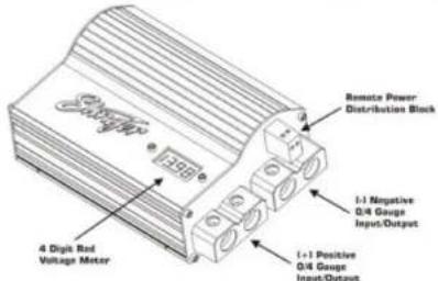
e) Over voltage limit and low battery voltage limit warning. When the system voltage goes ABOVE 17 DCV or BELOW 10 DCV. The buzzer will sound.
INSTALLATION AND MOUNTING:
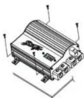
You must first attach the mounting tabs to the capacitor before mounting it. Use the supplied hardware shown in the picture below. Notice the small mounting screw hole in the capacitor chassis.
MOUNTING
CHARGING THE CAPACITOR AND WIRING:
The capacitor must be charged before connecting the Power and Ground cables to the capacitor. Failure to charge the capacitor will result in a large spark generated from the rapid inflow of current.
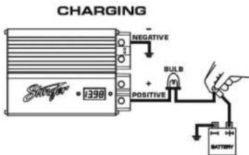
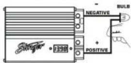
Figure 1
TO CHARGE THE CAPACITOR:
- Make Capacitor positive terminal connections with amplifier and tighten the bolt. Do not over tighten the bolts!
Caution : Stripped terminals are not covered under the capacitor's warranty.
-
Connect the ground cables of the battery, amplifier, and capacitor separately to chassis, and then refer to Fig.1.
-
Place the supplied charging bulb or resistor between the positive terminal of the capacitor and the battery's positive terminal. Do this for 10 minutes or until the charging bulb goes out.
Caution: The charging bulb will get hot!
- Immediately after the charging process, take away the charging bulb from the connecting wire, and connect the positive cable to the positive terminal on the capacitor.
DISCHARGING THE CAPACITOR:
Before removing capacitor we recommend discharging it: First, disconnect either supply wire; grounds or power from the capacitor. Next, place the light bulb, which came with your capacitor, across the power and ground terminals of the capacitor. It may take several minutes for the bulb to extinguish. Once bulb is no longer lit, you can continue disconnecting the wiring and dismount the capacitor.
DISCHARING
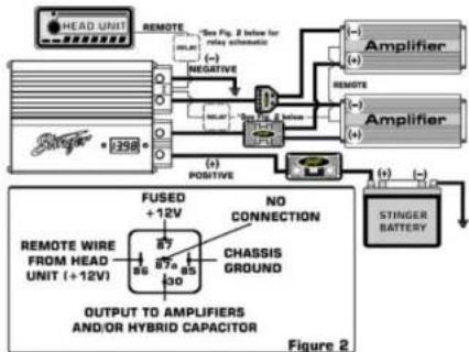
MULTIPLE CAPACITOR WIRING DIAGRAM:
flowchart
graph TD
    A["HEAD UNIT"] --> B["REMOTE"]
    B --> C["Amplifier"]
    C --> D["Stinger Battery"]
    D --> E["FUSED +12V"]
    E --> F["OUTPUT TO AMPLIFIERS AND/OR HYBRID CAPACITOR"]
    F --> G["Chassis Ground"]
    G --> H["REMOTE WIRE FROM HEAD UNIT (+12V)"]
    H --> I["FUSED +12V"]
    I --> J["NO CONNECTION"]
    J --> K["OUTPUT TO AMPLIFIERS AND/OR HYBRID CAPACITOR"]
    K --> L["STINGER BATTERY"]
    style A fill:#f9f,stroke:#333
    style C fill:#ccf,stroke:#333
    style D fill:#cfc,stroke:#333
    style E fill:#fcc,stroke:#333
    style F fill:#cff,stroke:#333
    style G fill:#ffc,stroke:#333
    style H fill:#cfc,stroke:#333
    style I fill:#fcc,stroke:#333
    style J fill:#ffc,stroke:#333
    style K fill:#cfc,stroke:#333
    style L fill:#fcc,stroke:#333
NOTE: Wire standard SPDT (Single Pole Double Throw) relay in either location as shown in above diagram, use figure 2 schematic for reference.
Brand : Stinger
Model : SPC5050
Category : Uncategorized