DNC10LC - Carte réseau/Adaptateur Allied Telesis - Free user manual and instructions
Find the device manual for free DNC10LC Allied Telesis in PDF.


| Product Type | Network Adapter |
| Model | DNC10LC |
| Brand | Allied Telesis |
| Interface | PCI 32-bit bus |
| Network Speed | 10/100 Mbps (Fast Ethernet) |
| Connector Type | RJ-45 |
| Standards Compliance | IEEE 802.3, 802.3u, 802.3x |
| Auto-Negotiation | Yes (10/100, half/full duplex) |
| LED Indicators | Link/Activity, Speed |
| Dimensions (approx.) | 12 x 6 x 1.5 cm (4.7 x 2.4 x 0.6 in) |
| Weight (approx.) | 0.05 kg (0.11 lb) |
| Power Consumption | 2.5 W typical |
| Operating Temperature | 0°C to 50°C (32°F to 122°F) |
| Storage Temperature | -20°C to 70°C (-4°F to 158°F) |
| Operating Humidity | 10% to 90% non-condensing |
| Supported OS | Windows 95/98/ME/NT4/2000/XP, Linux, Novell NetWare |
| Warranty | Limited lifetime (check manufacturer) |
Frequently Asked Questions - DNC10LC Allied Telesis
User questions about DNC10LC Allied Telesis
0 question about this device. Answer the ones you know or ask your own.
Ask a new question about this device
Download the instructions for your Carte réseau/Adaptateur in PDF format for free! Find your manual DNC10LC - Allied Telesis and take your electronic device back in hand. On this page are published all the documents necessary for the use of your device. DNC10LC by Allied Telesis.
USER MANUAL DNC10LC Allied Telesis
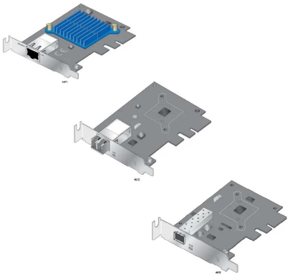
Single 10G Port Network Interface Cards with PCIe x4 Express Interface
□ DNC10T
□ DNC10LC
□ DNC10SP
Installation and User's Guide
Copyright © 2020 Allied Telesis, Inc.
All rights reserved. No part of this publication may be reproduced without prior written permission from Allied Telesis, Inc.
Allied Telesis and the Allied Telesis logo are trademarks of Allied Telesis, Incorporated. All other product names, company names, logos or other designations mentioned herein are trademarks or registered trademarks of their respective owners.
Allied Telesis, Inc. reserves the right to make changes in specifications and other information contained in this document without prior written notice. The information provided herein is subject to change without notice. In no event shall Allied Telesis, Inc. be liable for any incidental, special, indirect, or consequential damages whatsoever, including but not limited to lost profits, arising out of or related to this manual or the information contained herein, even if Allied Telesis, Inc. has been advised of, known, or should have known, the possibility of such damages.
This product meets the following standards.
Federal Communications Commission Interference Statement
Declaration of Conformity
Manufacturer Name: Allied Telesis, Inc.
Declares that the product: DNC10 Series 1 Port 10G Network Interface Card (w/PCI x4 Express Interface)
Model Numbers: DNC10LC, DNC10SP, and DNC10T
This equipment has been tested and found to comply with the limits for a Class B digital device, pursuant to Part 15 of FCC Rules. These limits are designed to provide reasonable protection against harmful interference in a residential installation. This equipment generates, uses and can radiate radio frequency energy and, if not installed and used in accordance with the instructions, may cause harmful interference to radio or television reception. However, there is no guarantee that interference will not occur in a particular installation. If this equipment does cause harmful interference to radio or television reception, which can be determined by turning the equipment off and on, the user is encouraged to try to correct the interference by one of the following measures:
- Reorient or relocate the receiving antenna.
- Increase the separation between the equipment and the receiver.
- Connect the equipment into an outlet on a circuit different from that to which the receiver is connected.
- Consult the dealer or an experienced radio/TV technician for help.
This device complies with part 15 of the FCC Rules. Operation is subject to the following two conditions:
(1) This device must not cause harmful interference, and
(2) this device must accept any interference received, including interference that may cause undesired operation.
FCC Caution: Any changes or modifications not expressly approved by the party responsible for compliance could void the user's authority to operate this equipment.
IMPORTANT NOTE:
FCC Radiation Exposure Statement:
This equipment complies with FCC radiation exposure limits set forth for an uncontrolled environment. End users must follow the specific operating instructions for satisfying RF exposure compliance.
Industry Canada
This Class B digital apparatus meets all requirements of the Canadian Interference-Causing Equipment Regulations.
European Union Restriction of the Use of Certain Hazardous Substances (RoHS) in Electrical and Electronic Equipment
This Allied Telesis RoHS-compliant product conforms to the European Union Restriction of the Use of Certain Hazardous Substances (RoHS) in Electrical and Electronic Equipment. Allied Telesis ensures RoHS conformance by requiring supplier Declarations of Conformity, monitoring incoming materials, and maintaining manufacturing process controls.
RFI Emissions FCC Class B, EN55032 Class B, VCCI Class B, ICES-003 Issue 6
Immunity EN55035
Electrical Safety EN2368-1 (TUV), UL 62368-1 (cUL _US )

Laser Safety EN60825
Important: Safety statements that have the Ⓗ symbol are translated into multiple languages in the Translated Safety Statements document at www.alliedtelesis.com/library.
Safety Symbols Used in this Document....14
Contacting Allied Telesis....15
Chapter 1: Introduction ...... 17
Functional Description....18
DNC10LC Fiber Optic Port 20
DNC10SP SFP+ Port 21
DNC10T Twisted Pair Copper Port 23
Features....25
Hardware 25
Software 25
Chapter 2: Installing the Hardware ....27
System Requirements....28
Reviewing Safety Precautions 29
Pre-Installation Checklist....31
Replacing the Bracket....32
Installing a Network Adapter 34
Connecting the Network Cable 38
DNC10LC Fiber Optic Cable 38
DNC10SP SFP+ Transceiver 38
DNC10T Twisted-Pair Copper Cable 39
Chapter 3: Installing the Driver Software ....41
Overview 42
Guidelines....42
Installing the Driver Using the Device Manager 42
Installing the Driver Using the Silent Installation Method 42
Downloading the Driver Software....43
Accessing the Device Manager....45
Installing the Driver Software 47
Updating the Driver Software....51
Performing the Silent Installation 52
Installing the Driver Silently 52
Viewing Supported DPInst Options 53
Chapter 4: Modifying Advanced Properties ....55
Overview 57
Guidelines....57
Accessing Advanced Properties 58
ARP Offload 60
Downshift Retries 61
Energy-Efficient Ethernet 62
Flow Control....63
Interrupt Moderation....65
Interrupt Moderation Rate 66
IPv4 Checksum Offload 68
Contents
Jumbo Packet 69
Large Send Offload v1 (IPv4) 71
Large Send Offload v2 (IPv4) 72
Large Send Offload v2 (IPv6) 73
Link Speed....74
Locally Administered Address 76
Log Link State Event 78
Maximum Number of RSS Queues 79
NS Offload 80
Priority & VLAN 81
Receive Buffers 83
Receive Side Scaling....84
Recv Segment Coalescing (IPv4) 85
Recv Segment Coalescing (IPv6)....87
TCP/UDP Checksum Offload (IPv4) 89
TCP/UDP Checksum Offload (IPv6) 91
Transmit Buffers 93
VLAN ID 94
VLAN Monitor Mode 95
Wait for Link....97
Wake from Power Off State 99
Wake on Link....101
Wake on Magic Packet....102
Wake on Pattern Match 103
Wake on Ping 104
Chapter 5: Uninstalling the Driver Software .... 105
Overview....106
Guidelines 106
Uninstalling the Driver Software Using Device Manager 107
Uninstalling the Driver Software Silently.... 108
Chapter 6: Troubleshooting .... 109
Troubleshooting Checklist 110
General Troubleshooting.... 110
DNC10LC Adapter 110
DNC10SP Adapter 111
DNC10T Adapter.... 112
Testing Network Connectivity 113
Appendix A: Technical Specifications 115
Physical Specifications 115
Environmental Specifications 116
Power Specifications 116
RJ-45 Twisted Pair Port Pinouts.... 117
Tables
Table 1. DNC10 Series Network Interface Cards ...... 19
Table 2. DNC10LC LED Status 20
Table 3. DNC10SP LED Status ......22
Table 4. DNC10T Link and Activity LEDs ......24
Table 5. Weights ......115
Table 6. Dimensions ...... 115
Table 7. Environmental Specifications ...... 116
Table 8. Operating Voltages and Maximum Power Consumption ...... 116
Table 9. Pin Signals on the RJ-45 Twisted Pair Port at 100Mbps ......117
Table 10. Pin Signals on the Twisted Pair Port at 1/2.5/5/10Gbps 118
List of Tables
Figures
Figure 1: DNC10LC Adapter Card....20
Figure 2: Duplex LC Connector on the DNC10LC Network Adapter.... 20
Figure 3: DNC10SP Adapter Card....22
Figure 4: SFP+ Port on the DNC10SP Adapter....22
Figure 5: DNC10T Adapter Card 23
Figure 6: Twisted Pair Cable Port....23
Figure 7: Removing the Low-Profile Bracket 32
Figure 8: Fastening Screws onto Standard Bracket 33
Figure 9: Removing the PC Cover.... 35
Figure 10: Removing the Faceplate From PCIe Slot.... 35
Figure 11: Inserting the Network Adapter 36
Figure 12: Securing the Network Adapter.... 36
Figure 13: Software Downloads Search Result Example 43
Figure 14: Login Window 44
Figure 15: Select a Destination and Extract 44
Figure 16: Windows Menu....45
Figure 17: Device Manager Window....46
Figure 18: Searching for Device Manager 46
Figure 19: Selecting the DNC10 Series Adapter in the Device Manager 48
Figure 20: Update Driver Software Window 49
Figure 21: Browse for Drivers on Your Computer.... 49
Figure 22: Advanced Properties Window 59
Figure 23: ARP Offload Page 60
Figure 24: Downshift Retries Page 61
Figure 25: Energy-Efficient Ethernet Page 62
Figure 26: Flow Control Page 63
Figure 27: Interrupt Moderation Page....65
Figure 28: Interrupt Moderation Rate Page 66
Figure 29: IPv4 Checksum Offload Page 68
Figure 30: Jumbo Packet Page 69
Figure 31: Large Send Offload v1 (IPv4) Page 71
Figure 32: Large Send Offload v2 (IPv4) Page....72
Figure 33: Large Send Offload (IPv6) Page 73
Figure 34: Link Speed Page 74
Figure 35: Locally Administered Address Page 76
Figure 36: Log Link State Event Page 78
Figure 37: Maximum Number of RSS Queues Page.... 79
Figure 40: Receive Buffers Page....83
Figure 41: Receive Side Scaling Page 84
Figure 42: Receive Segment Coalescing (IPv4) Page 85
Figure 43: Receive Segment Coalescing (IPv6) Page 87
Figure 44: TCP/UDP Checksum Offload (IPv4) Page 89
Figure 45: TCP/UDP Checksum Offload (IPv6) Page 91
Figure 46: Transmit Buffers Page....93
Figure 47: VLAN ID Page 94
Figure 48: VLAN Monitor Mode Page 95
Figure 49: Wait for Link Page....97
List of Figures
Figure 50: Wake from Power Off State Page....99
Figure 51: Wake on Link Page.... 101
Figure 52: Wake on Magic Packet Page....102
Figure 53: Wake on Pattern Match Page....103
Figure 54: Wake on Ping Page....104
Figure 55: Device Manager Shortcut Menu 107
Figure 56: IPCONFIG Command.... 114
Figure 57: Ping Command....114
Figure 58: Pin Layout (Front View) of the Twisted Pair Port on the DNC10T Adapter 117
This guide contains instructions on how to install and configure the DNC10 Series adapters.
The Preface discusses the following topics:
☐ “Safety Symbols Used in this Document” on page 14
☐ “Contacting Allied Telesis” on page 15
This guide contains the installation instructions for the following single 10G port Network Interface Cards (NICs).
□ DNC10SP
□ DNC10LC
□ DNC10T
Safety Symbols Used in this Document
This document uses the following conventions:
Note
Notes provide additional information.

Caution
Cautions inform you that performing or omitting a specific action may result in equipment damage or loss of data.

Warning
Warnings inform you that performing or omitting a specific action may result in bodily injury.

Warning
Laser warnings inform you that an eye or skin hazard exists due to the presence of a Class 1 laser device.
Contacting Allied Telesis
If you need assistance with this product, you may contact Allied Telesis technical support by going to the Support & Services section of the Allied Telesis web site at www.alliedtelesis.com/support. You can find links for the following services on this page:
☐ 24/7 Online Support - Enter our interactive support center to search for answers to your questions in our knowledge database, check support tickets, learn about Return Merchandise Authorizations (RMAs), and contact Allied Telesis technical experts.
☐ USA and EMEA phone support - Select the phone number that best fits your location and customer type.
☐ Hardware warranty information - Learn about Allied Telesis warranties and register your product online.
□ Replacement Services - Submit an RMA request via our interactive support center.
□ Documentation - View the most recent installation guides, user guides, software release notes, white papers and data sheets for your product.
☐ Software Updates - Download the latest software releases for your product.
For sales or corporate contact information, select your region and country, then go to www.alliedtelesis.com/contact.
Preface
This chapter provides an introduction to the DNC10 Series network interface cards (NICs) with Wake-on-LAN (WoL).
This chapter contains the following sections:
☐ “Functional Description” on page 18
☐ "DNC10LC Fiber Optic Port" on page 20
☐ "DNC10SP SFP+ Port" on page 21
☐ "DNC10T Twisted Pair Copper Port" on page 23
☐ “Features” on page 25
Functional Description
The DNC10 Series network adapters are 10 Gigabit Ethernet (10GbE) interface controllers that are based on the Aquantia AQC100 10GbE media access controller (MAC) with integrated serializer/deserializer (SerDes).
The Aquantia diagnostic tool can be used with the device to provide firmware programming and a first level of diagnostics and fault isolation.
These cards have Peripheral Component Interconnect Express (PCIe) bus connectors. The DNC10 Series network adapters support the PCIe x4 v3.0, 2.1 and 1.1a compliant interfaces.
The AT-DNC10 Series can perform accelerated Ethernet data networking and storage networking simultaneously for all popular protocols used in the data center, and includes features such as Data Center Bridging.
Enterprise networks that use multiple protocols and multiple network fabrics benefit from the ability of the network interface card (NIC) to combine data communications, storage, and clustering over a single Ethernet fabric and to boost server CPU performance and memory utilization while alleviating I/O bottlenecks.
Wake-on-LAN (WoL) is a protocol for remotely turning on a computer in a low power mode with a network message. A magic packet is a network message that a WoL-enabled computer receives and wakes up when the computer's MAC address matches one in the magic packet.
As part of the company's green range, the adapter is engineered to reduce power consumption. It incorporates centralized power management features that automatically place idle circuitry into a lower power mode to save energy.
The basic characteristics of the NICs are listed in Table 1.
Table 1. DNC10 Series Network Interface Cards
| Adapter Port Speed Cable Type | Maximum Distance | System Connection | |||
| DNC10SP SF | P+ 10G/1G Varies by | SFP+ transceiver | Varies by SFP+ transceiver | PCIe x4 (Gen 3) | |
| DNC10LC Duplex LC 10G OM1 33m PCIe x4 | (Gen 3) | ||||
| OM2 | 82m | ||||
| OM3 | 300m | ||||
| OM4 550m | |||||
| DNC10T RJ45 10G CAT6A | 100m PCIe x4 | (Gen 3) | |||
| 5G/2.5G/1G/100M | CAT5e or CAT6A | ||||
Note
The maximum operating distance of the SFP+ port on the DNC10SP adapter depends on the transceiver. Refer to the product's data sheet on the Allied Telesis web site for a list of supported transceivers.
After physically installing the DNC10 Series network adapter in your computer, install the driver software by referring to Chapter 3, "Installing the Driver Software" on page 41.
DNC10LC Fiber Optic Port
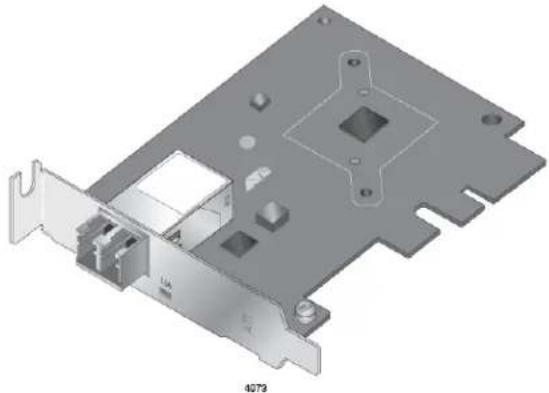
The DNC10LC adapter card has one 10Gbps fiber optic port with a duplex LC connector. The port has a maximum operating distance of 300m with OM3 fiber optic cable. The DNC10LC links at 10G only. It has one LED to show the networking state.
The DNC10LC has a PCIe x4 motherboard bus interface as shown in Figure 1.
natural_image
3D technical illustration of a computer RAM card with mounting bracket and internal components (no text or symbols)Figure 1. DNC10LC Adapter Card
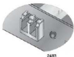
The LC fiber optic adapter port is shown in Figure 2.
natural_image
3D mechanical component diagram with no visible text or symbolsFigure 2. Duplex LC Connector on the DNC10LC Network Adapter
Table 2 describes the link states that the LED indicates.
Table 2. DNC10LC LED Status
| Port LED LED State Description | |
| L/A (Link/Activity) | Solid Green The port has established a link with a network device. |
| Off The port has not established a link with a network device. | |
| Flashing Green The port is receiving or transmitting network packets. | |
The DNC10SP adapter has an SFP+ port where you can plug in an SFP+ transceiver to connect the adapter to a compatible link partner. The DNC10SP will detect whether a 10G SFP+ or 1G SFP has been inserted and will only operate at that speed. It has one LED to show the networking state.
You cannot change the speed or duplex mode of the transceiver port. The maximum operating distance of an SFP+ port will vary depending on the SFP+ transceiver and type of fiber optic cabling.
The port supports the following types of transceivers:
Note
See the Allied Telesis website for supported SFP models.
☐ 1Gbps SPSX and SPLX short and long distance SFP transceivers using multi-mode or single mode fiber optic cable.
☐ 10Gbps SP10SR and SP10LR SFP+ short and long distance SFP+ transceivers using multi-mode or single mode fiber optic cable.
☐ 10Gbps SP10BD series of bidirectional transceivers for single mode fiber optic cable with maximum operating distances of 10 to 40 kilometers.
☐ 10Gbps SP10TW series of direct connect twinax cables with SFP+ transceiver-style connectors, in lengths of 1, 3, and 7 meters.
☐ 10Gbps SP10T transceiver with RJ-45 connector for links up to 20 meters (depending on SFP) with Category 6a twisted pair cable, or 100 meters at 1Gbps.
Guidelines for the port are listed here:
☐ It does not support 100Mbps-FX transceivers.
☐ It supports full-duplex mode only.
☐ The adapter can set the speed automatically with Auto-Negotiation. The default is Auto-Negotiation.
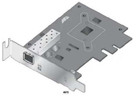
The DNC10SP adapter has a PCIe x4 motherboard bus interface as shown in Figure 3.
natural_image
3D CAD rendering of a computer RAM card with port and mounting bracket (no text or symbols)Figure 3. DNC10SP Adapter Card
Note
An SFP+ transceiver must be purchased separately. For a list of supported transceivers, refer to the product's data sheet on the Allied Telesis web site.
The SFP+ port is shown in Figure 4.
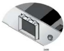
Figure 4. SFP+ Port on the DNC10SP Adapter
Table 2 describes the link states that the LED indicates.
Table 3. DNC10SP LED Status
| Port LED LED State Description | ||
| L/A (Link/Activity) | Solid Green T | The port has established a link with a network device. |
| Off The port h | has not established a link with a network device. | |
| Flashing Green | The port is receiving or transmitting network packets. | |
DNC10T Twisted Pair Copper Port
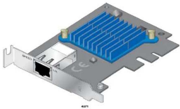
The DNC10T adapter card has one copper port that can operate at 100Mbps or 1/2.5/5/10Gbps. The card uses Auto-Negotiation to automatically set port speed and supports full-duplex mode only. The port has two status LEDs.
The adapter has a PCIe x4 motherboard bus connector as shown in Figure 5.
natural_image
3D rendering of a computer motherboard with blue heat sinks and an Ethernet port (no text or symbols visible)Figure 5. DNC10T Adapter Card
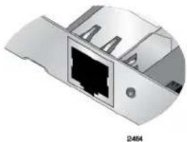
The twisted pair cable port is shown in Figure 6.
natural_image
3D rendering of a device housing with internal components and a labeled section (no text or symbols on the diagram itself)Figure 6. Twisted Pair Cable Port
The minimum cable requirements are listed here:
☐ 100Mbps - Standard TIA/EIA 568-A-compliant Category 5 twisted pair cabling
☐ 1/2.5/5Gbps - Standard TIA/EIA 568-B-compliant Category 5e twisted pair cabling
☐ 10Gbps - Standard TIA/EIA 568-C-compliant Category 6A twisted pair cabling
The port has a maximum operating distance of 100 meters (328 feet).
The LEDs for the twisted pair port are described in Table 4.
Table 4. DNC10T Link and Activity LEDs
| Port LEDs | LED State Network State | |
| Left Green | Steady On The transceiver has established a 10G link to a remote device. | |
| Amber Steady On The transceiver has established a 100Mbps or 1/2.5/5G link to a remote device. The user will need to check connection properties in the OS to determine the actual link speed. | ||
| Off The port has not established a link. | ||
| Right Green | Steady On The transceiver has established a link to a remote device. | |
| Green Blinking The transceiver in the port is transmitting or receiving network traffic. | ||
| Off The port has not established a link. | ||
Features
Here are the key features of the DNC10 Series network interface cards:
Hardware □ DNC10SP supports one SFP+ port
☐ DNC10LC supports one fiber optic port with a duplex LC connector port
☐ DNC10T supports one twisted pair port
☐ PCIe v3.0, 2.1, and 1.1a compliant
☐ TCP, IP, and UDP checksum
☐ Virtual LANs (VLANs) - 802.1q VLAN tagging
☐ Jumbo Frame support up to 16 KBytes
☐ Advanced Configuration and Power Interface (ACPI) power management compliant
□ Low profile form factor
□ RoHS compliant
☐ Preboot Execution Environment (PXE) v2.1
□ Unified Extensible Firmware Interface (UEFI)
☐ Low profile and standard bracket
□ Wake-on-LAN (WoL)
☐ Quality of Service (QoS) support up to eight traffic classes
□ Data Center Bridging (DCB)
Software □ Windows 10, 64-bit
□ Windows Server 2016
□ Windows Server 2019
☐ Linux with kernel version 3.10 and higher
Chapter 1: Introduction
Chapter 2
Installing the Hardware
This chapter contains the following sections:
☐ "System Requirements" on page 28
☐ “Reviewing Safety Precautions” on page 29
☐ "Pre-Installation Checklist" on page 31
☐ "Replacing the Bracket" on page 32
☐ "Installing a Network Adapter" on page 34
☐ “Connecting the Network Cable” on page 38
System Requirements
Before installing the DNC10 series network adapter, make sure your system meets the requirements listed below:
☐ Computer with one of the following operating systems installed:
- Windows 10, 64-bit
- Windows Server 2016
- Windows Server 2019
– Linux with kernel version 3.10 and higher
☐ One open PCIe x4 or larger slot
Reviewing Safety Precautions
Important: Safety statements that have the ⬤ symbol are translated into multiple languages in the Translated Safety Statements document at www.alliedtelesis.com/library.
Do not stare into the laser beam. ∞ L2

Warning
The fiber optic ports contain a Class 1 laser device. When the ports are disconnected, always cover them with the provided plug. Exposed ports may cause skin or eye damage. L4

Warning
Do not look directly at the fiber optic cable ends or inspect the cable ends with an optical lens. L6

Warning
Do not work on this equipment or cables during periods of lightning activity. E2

Warning
Operating Temperature: This product is designed for a maximum ambient temperature of 40 degrees C. E7
Note
All Countries: Install this product in accordance with local and National Electric Codes. E8

Warning
The module is being installed in a system that operates with voltages that can be lethal. Before you remove the cover of your system, you must observe the following precautions to protect yourself and to prevent damage to the system components.
- Remove any metallic objects or jewelry from your hands and wrists.
- Make sure to use only insulated or nonconducting tools.
- Verify that the system is powered OFF and unplugged before accessing internal components.
- Installation or removal of modules must be performed in a static-free environment. The use of a properly grounded wrist strap or other personal antistatic devices and an antistatic mat is strongly recommended. E39

Caution
Do not use excessive force when seating the card, as the force may damage the system or the adapter card. If the card resists seating, remove it from the system, realign it, and try again. E47
Pre-Installation Checklist
Before installing the DNC10 series network adapter, check the following list:
- Check that your computer has an appropriate open PCIe slot.
- Verify that your system is using the latest BIOS.
- When you download the driver software from the Allied Telesis website, record the path to where the driver file resides on your system.
- If your system is active, shut it down.
- When system shutdown is complete, unplug your system.
- Holding the adapter card by the edges, remove it from its shipping package and place it on an antistatic surface.
- Check the adapter for visible signs of damage, particularly on the card's edge connector.
Note
Do not attempt to install any damaged adapter card. If the adapter card is damaged, report it to Allied Telesis. See “Contacting Allied Telesis” on page 15.
Replacing the Bracket
The DNC10 series network adapter is shipped with the low-profile bracket attached to the adapter. Additionally, a standard bracket is supplied also. Depending on your system, you may need to replace the bracket attached to your adapter card.
The following procedure describes how to remove the low-profile bracket from the network adapter and replace it with the standard bracket. You can also use this procedure to remove the standard bracket and replace it with the low-profile bracket.
To replace the low-profile bracket with the standard bracket, perform the following procedure:
- Remove the screws that attach the bracket to the network adapter. See Figure 7.
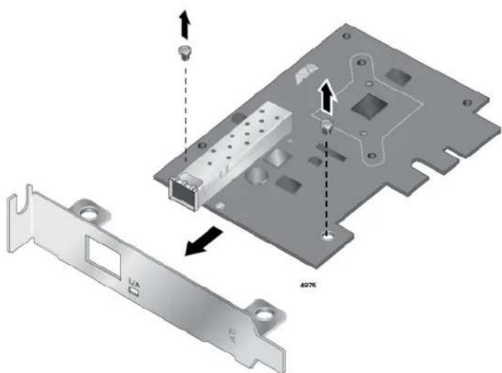
Figure 7. Removing the Low-Profile Bracket
- Align the tabs of the standard bracket with the holes on the network adapter and fasten the screws onto the network adapter. See Figure 8 on page 33.
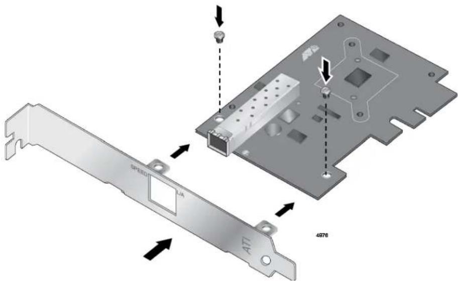
Figure 8. Fastening Screws onto Standard Bracket
Installing a Network Adapter
The following instructions apply to installing a DNC10 series network adapter in most systems. Refer to the manuals that were supplied with your system for details about performing these tasks on your particular system.
To install the network adapter, perform the following procedure:
- Review the "Pre-Installation Checklist" on page 31 and "Reviewing Safety Precautions" on page 29.
Before installing the network adapter, ensure the system power is OFF and unplugged from the power outlet, and that proper electrical grounding procedures have been followed.

Warning
The module is being installed in a system that operates with voltages that can be lethal. Before you remove the cover of your system, you must observe the following precautions to protect yourself and to prevent damage to the system components.
- Remove any metallic objects or jewelry from your hands and wrists.
- Make sure to use only insulated or nonconducting tools.
- Verify that the system is powered OFF and unplugged before accessing internal components.
-
Installation or removal of modules must be performed in a static-free environment. The use of a properly grounded wrist strap or other personal antistatic devices and an antistatic mat is strongly recommended. E39
-
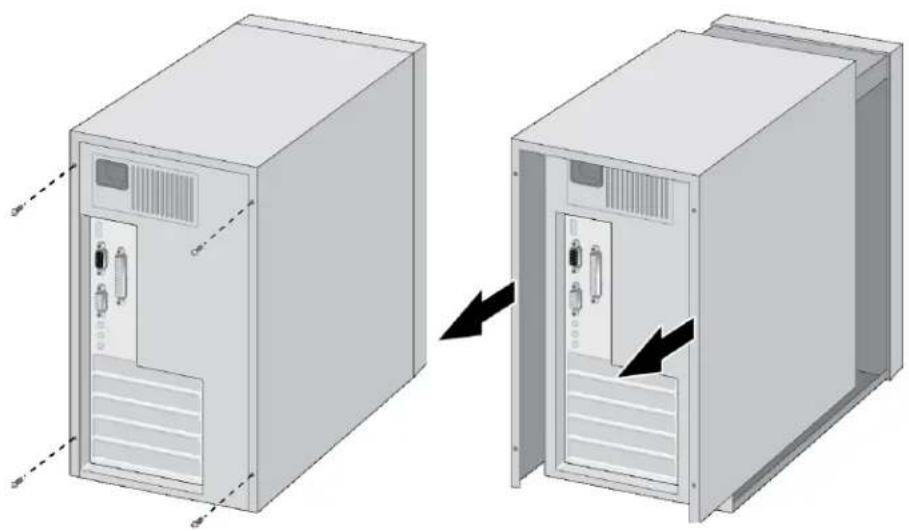
Remove the system cover and select any empty PCIe slot. See Figure 9 on page 35.
If you do not know how to identify a PCIe x4 or larger slot, refer to your system documentation.
natural_image
Diagram showing two views of a server rack cabinet with internal components, one being rotated and the other closed, both without any text or symbols.Figure 9. Removing the PC Cover
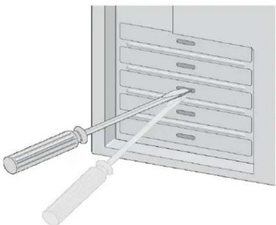
- Select an empty, non-shared PCIe slot and remove the faceplate.
Keep the faceplate in a safe place. You may need it for future use. See Figure 10.
natural_image
Illustration of a screwdriver inserted into a rack with multiple slots (no text or symbols)Figure 10. Removing the Faceplate From PCIe Slot
-
Remove the network adapter from the shipping package and store the packaging material in a safe location.
-
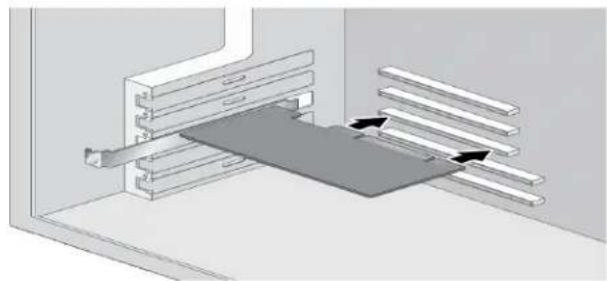
Applying even pressure at both corners of the network adapter, push the adapter until it is firmly seated in the PCIe slot.
Make sure the adapter is securely seated. See Figure 11 on page 36.
natural_image
Technical diagram showing a mechanical assembly with layered components and directional arrows indicating movement (no text or symbols present)Figure 11. Inserting the Network Adapter

Caution
Do not use excessive force when seating the adapter, as the force may damage the system or the adapter. If the adapter resists seating, remove it from the system, realign it, and try again. E47
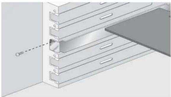
- Secure the network adapter to the chassis with a Phillips-head screw (not provided) as shown in Figure 12.
natural_image
3D technical illustration of a cabinet or rack assembly with metal components and a highlighted section (no text or symbols)Figure 12. Securing the Network Adapter
-
Replace the system's cover and secure it with the screws removed in step 2.
-
Disconnect any personal antistatic devices.
9. Power the system on.
When the system returns to proper operation, the network adapter is fully installed. Next, connect the network cables. See “Connecting the Network Cable” on page 38.
Connecting the Network Cable
DNC10LC Fiber Optic Cable
Depending on the type of DNC10 series network adapter installed, it is equipped with an SFP+, fiber optic, or copper RJ45 port. To connect the network adapter to the network, you must have a cable with the appropriate connector.
To connect a fiber optic network cable to the duplex LC connector on the DNC10LC network adapter, perform the following procedure:
- Prepare a fiber optic cable with an appropriate connector.

Warning
The fiber optic ports contain a Class 1 laser device. When the ports are disconnected, always cover them with the provided plug. Exposed ports may cause skin or eye damage. ∞ L4
- Remove the dust cover from the duplex LC connector on the fiber optic port.
- Connect one end of the cable to the network adapter.
- Connect the other end of the cable to the fiber optic port on a remote network device.
- Load the driver as described in Chapter 3, "Installing the Driver Software" on page 41.
DNC10SP SFP+ Transceiver
The network adapter requires an SFP+ transceiver and an appropriate cable to connect to the network.
- Insert an SFP+ transceiver into the SFP+ port on the network adapter until the SFP+ transceiver snaps into place in the port.
- Remove the dust cover from the SFP+ transceiver.
- Connect one end of the cable to the SFP+ transceiver.
- Connect the other end of the cable to the appropriate fiber optic port on a remote network device.
- Load the driver as described in Chapter 3, "Installing the Driver Software" on page 41.
DNC10T Twisted-Pair Copper Cable
To connect a copper network cable to the network adapter, perform the following procedure.
- Prepare a twisted-pair copper cable.
- Connect one end of the cable to the network adapter.
- Connect the other end of the cable to the appropriate port on a remote network device.
- Load the driver as described in Chapter 3, "Installing the Driver Software" on page 41.
Chapter 2: Installing the Hardware
Chapter 3
Installing the Driver Software
This chapter describes how to install driver software for the DNC10 Series network adapter onto your operating system. It contains the following topics:
☐ “Overview” on page 42
☐ "Downloading the Driver Software" on page 43
☐ “Accessing the Device Manager” on page 45
☐ "Installing the Driver Software" on page 47
☐ "Updating the Driver Software" on page 51
☐ “Performing the Silent Installation” on page 52
Overview
After you install the DNC10 Series network adapter on your computer, your next step is to install the driver software onto your Windows operating system. You can install the driver software using the Device Manager or the silent installation method.
When you install the driver software using the Device Manager, the dialog boxes guide you through the installation process. On the other hand, using the silent installation method, you can install software without constant interactions by suppressing dialog boxes.
Guidelines
Here are the guidelines for installing and updating the driver software on your operating system:
☐ To install or update the driver software, you must have administrative privileges.
☐ When you install the DNC10 Series network adapter on your computer and start the system, the system detects a new adapter and may install a default driver. In either case, you must update the driver software for the DNC10 Series network adapter. See “Installing the Driver Using the Device Manager”, or “Installing the Driver Using the Silent Installation Method”.
Installing the Driver Using the Device Manager
To install or update the driver software using the Device Manager, follow the steps below:
☐ "Downloading the Driver Software" on page 43
☐ “Accessing the Device Manager” on page 45
☐ "Installing the Driver Software" on page 47
Or
☐ "Updating the Driver Software" on page 51
Installing the Driver Using the Silent Installation Method
To install or update the driver software using the silent installation, follow the steps below:
☐ "Downloading the Driver Software" on page 43
☐ “Performing the Silent Installation” on page 52
Downloading the Driver Software
The driver software for the adapters is available on the Allied Telesis website. The driver is the same for all DNC10 Series NICs.
To download the software:
- Open a web browser, such as Internet Explorer or Firefox, on your computer and enter the following:
http://www.alliedtelesis.com/support/software
The Allied Telesis Software Download page is displayed as shown in Figure 13.
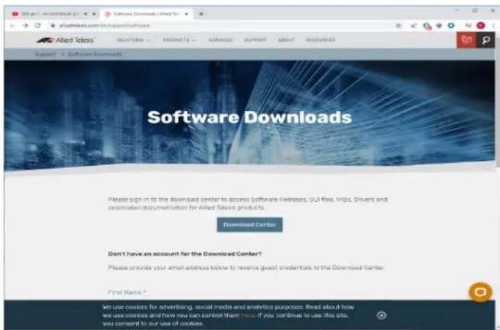
Figure 13. Software Downloads Search Result Example
- Click Support.
- Select Software Library.
- Complete the form to gain access to the Download Center.
- Check your email for the access Login ID and password.
-
Click Download Center.
-
Enter the Login ID and Password and click Login.
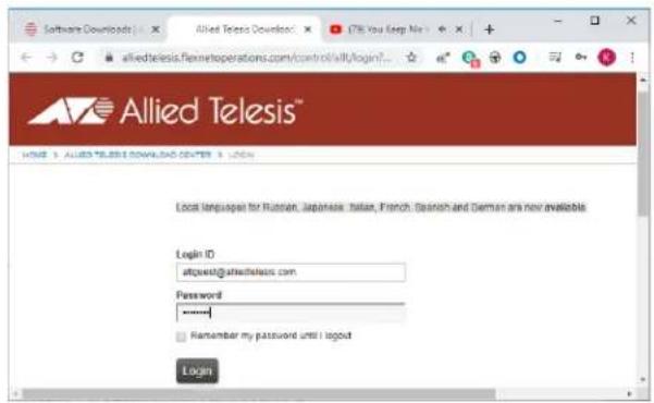
Figure 14. Login Window
- Select the driver for the DNC10 Series network adapter and your operating system.
- Save the zip folder onto your system.
- Right-click the zip folder and select Extract All.
A window appears and prompts you to specify the location of a folder where you want to place the unzipped files.
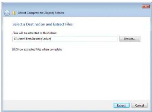
Figure 15. Select a Destination and Extract
- Specify the location of the folder and click Extract.
- Record the location of the folder.
Accessing the Device Manager
When you install or update the driver software for DNC10 Series network adapter, you must first access the Device Manager. The procedures for accessing the Device Manager are slightly different among Windows operating systems. To access the Device Manager on your operating system, follow one of the procedures below:
Option 1
To access the Device Manager on a Windows platform, do the following:
- Right-click the start button at the bottom left corner.
The Windows menu appears.
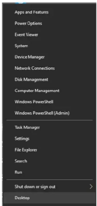
Figure 16. Windows Menu
- Select Device Manager in the search box.
The Device Manager window appears.
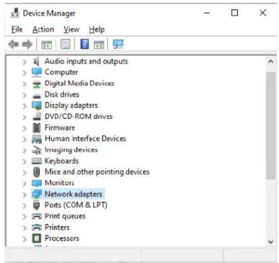
Figure 17. Device Manager Window
Option 2
Another option to accessing the Device Manager is:
- Type Device Manager in the search field at the bottom left corner. The following screen appears.
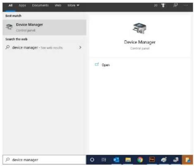
Figure 18. Searching for Device Manager
- Click on the Device Manager.
The Device Manager window appears as shown in Figure 17.
Installing the Driver Software
Once you physically install the DNC10 Series network card, the system detects the new hardware and creates an entry in the Device Manager when the Windows operating system first boots up. Shortly after you log in, you need to install the driver software for your adapter card.
Note
To install the driver software, you must have administrative privileges.
To install the driver software, do the following:
- Access the Device Manager, see "Accessing the Device Manager" on page 45.
- In the Device Manager window, double-click Network Adapters to expand the field.
- Option 1 - If the system has another network connection to provide Internet access:
a. Right-click on Aquantia device or Ethernet Controller (if no driver was installed).
b. Select Update Driver Software.
The Update Driver Software window appears. See Figure 20 as an example.
×
Update Drivers - Allied Telesis AT-DNC10 Series Ethernet #2
How do you want to search for drivers?
→ Search automatically for updated driver software Windows will search your computer and the Internet for the latest driver software for your device, unless you've disabled this feature in your device installation settings.
→ Browse my computer for driver software Locate and install driver software manually.
Cancel
c. Select Search automatically for updated driver software.
Windows will download the driver from Windows Update.
Option 2 - If the system does not have another network connection to provide Internet access:
a. Right-click on Allied Telesis DNC10 Series Fiber Ethernet.
Note
The Device Manager may identify the new DNC10 adapter as an Ethernet Controller, Aquantia device, or Allied Telesis device.
The shortcut menu appears. See Figure 19 as an example.
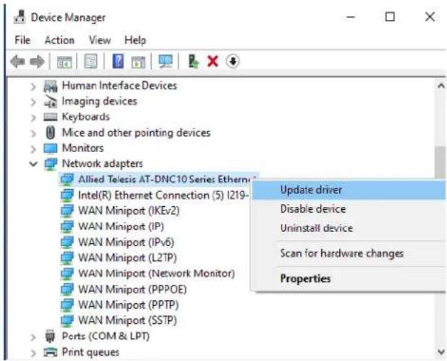
Figure 19. Selecting the DNC10 Series Adapter in the Device Manager
b. Select Update Driver Software.
The Update Driver Software window appears. See Figure 20 on page 49 as an example.
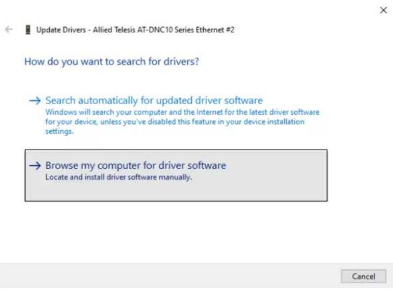
Figure 20. Update Driver Software Window
c. Select Browse my computer for driver software.
The Browse for Drivers on Your Computer window prompts you to enter the location of the driver folder. See Figure 21 as an example.
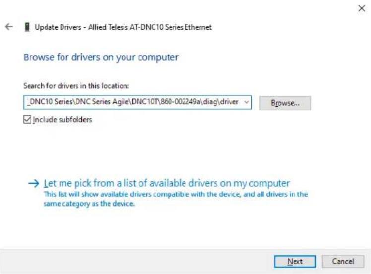
Figure 21. Browse for Drivers on Your Computer
-
Specify the location of the driver software. See "Downloading the Driver Software" on page 43 for details.
-
Click Next.
A confirmation message appears when the driver software is successfully updated.
- Click Close.
Updating the Driver Software
If your operating system automatically installs a default driver or Aquantia driver, you need to update the driver software with the driver that you downloaded from the Allied Telesis website. To obtain the latest version of the DNC10 Series network adapter driver, see “Downloading the Driver Software” on page 43.
To update the driver software, you use the same procedure for installing the driver software for the first time. The only difference between updating and installing the driver software is the name of your adapter that the Device Manager detects and lists.
The Device Manager lists your adapter card entry as Allied Telesis DNC10 Series Fiber Ethernet once you installed the driver software. Before you installed the driver software, the Device Manager may list your adapter entry as an Ethernet Controller, Aquantia device, or Allied Telesis device.
To update the driver software for your DNC10 Series network adapter, see "Installing the Driver Software" on page 47.
Performing the Silent Installation
To simplify the driver installation process, you may perform a silent installation when installing driver software for the DNC10 Series network adapter card entries. The silent installation is a method of installing software in the silent mode without constant interactions by suppressing dialog boxes.
Note
You can apply the silent installation method only to Microsoft certified drivers. The drivers that Allied Telesis provides for the DNC10 Series network adapters are all Microsoft certified.
Use a command line utility called Driver Package Installer (DPInst) for the silent installation. DPInst is included in the Windows Developer Kit (WDK) provided by Microsoft. You can obtain the latest DPInst by downloading and installing the latest WDK from the Microsoft website.
Installing the Driver Silently
To install the driver silently, perform the following instructions:
- Create a folder in your Windows system.
-
Download driver software for the DNC10 Series network adapter.
See "Downloading the Driver Software" on page 43. -
Place the driver files that you downloaded into the folder that you created in step 1.
The folder should include the following driver files:
□ .sys
□ .inf
□ .cat
- Download the latest WDK to obtain the dpinst utility.
Consult Microsoft websites to download WDK.
- Place the dpinst.exe and its supporting files in the same folder where you placed the driver files.
You must place the 64-bit dpinst utility if your operating system is the 64-bit version. Place the 32-bit for dpinst utility for the 32-bit version operating system.
-
Open a command prompt window with administrator privileges.
-
Change the directory to the folder where the dpinst utility and the driver files reside.
- Install the driver in the silent mode by entering the following command:
> dpinst /S
Note
Adding the /S switch to the dpinst command suppresses the display of wizard pages, user dialog boxes, and other user intervention requests.
The driver is installed silently.
Viewing Supported DPInst Options
You can display help information about the dpinst command-line options.
View all supported dpinst options by executing the following command:
- Open a command prompt window with administrator privileges.
- Change the directory to the folder where the dpinst utility and the driver files reside.
> dpinst /?
The command displays the help text.
Chapter 3: Installing the Driver Software
This chapter includes the following topics:
☐ "Overview" on page 57
☐ “Accessing Advanced Properties” on page 58
☐ "ARP Offload" on page 60
☐ "Downshift Retries" on page 61
☐ "Energy-Efficient Ethernet" on page 62
☐ "Flow Control" on page 63
☐ “Interrupt Moderation” on page 65
☐ “Interrupt Moderation Rate” on page 66
☐ "IPv4 Checksum Offload" on page 68
☐ "Jumbo Packet" on page 69
☐ "Large Send Offload v1 (IPv4)" on page 71
☐ “Large Send Offload v2 (IPv4)” on page 72
☐ “Large Send Offload v2 (IPv6)” on page 73
☐ "Link Speed" on page 74
☐ “Locally Administered Address” on page 76
☐ "Log Link State Event" on page 78
☐ "Maximum Number of RSS Queues" on page 79
☐ "NS Offload" on page 80
☐ "Priority & VLAN" on page 81
☐ "Receive Buffers" on page 83
☐ "Receive Side Scaling" on page 84
☐ “Recv Segment Coalescing (IPv4)” on page 85
☐ “Recv Segment Coalescing (IPv6)” on page 87
☐ “TCP/UDP Checksum Offload (IPv4)” on page 89
☐ “TCP/UDP Checksum Offload (IPv6)” on page 91
☐ “Transmit Buffers” on page 93
☐ "VLAN ID" on page 94
☐ "VLAN Monitor Mode" on page 95
☐ "Wait for Link" on page 97
☐ “Wake from Power Off State” on page 99
☐ “Wake on Link” on page 101
☐ “Wake on Magic Packet” on page 102
☐ “Wake on Pattern Match” on page 103
☐ “Wake on Ping” on page 104
Overview
The DNC10 series network adapters allow you to modify advanced properties to meet your requirements. To access the advanced properties, access Device Manager, then go to each advanced property page.
Guidelines Here are the guidelines to modifying the advanced properties:
☐ To change the advanced property settings, you must have Administrator privileges.
☐ When you upgrade the driver software, the settings of the advanced properties may change. Verify the settings after upgrading the driver software.
Accessing Advanced Properties
To modify advanced properties, first access Device Manager, open the properties of your adapter, and select a feature you want to change its setting.
- Access the Device Manager. See "Accessing the Device Manager" on page 45.
- In the Device Manager window, click Network Adapters.
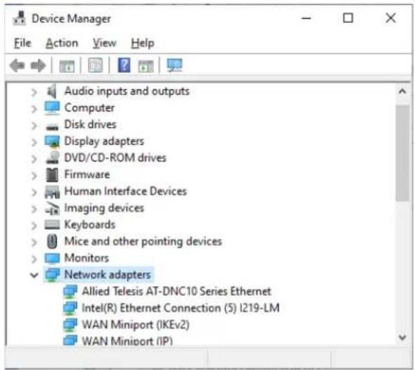
- Double-click Allied Telesis AT-2911GP Series Ethernet.
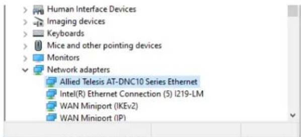
The properties window pops up.
- Click the Advanced tab.
The Advanced Properties window opens as shown in Figure 22.
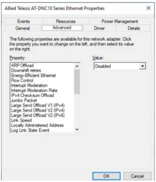
Figure 22. Advanced Properties Window
ARP Offload
The ARP Offload feature enables the adapter not to wake up when responding to an ARP request. ARP is used to verify whether a computer is still present on the network and resolve an IP address into a MAC address.
To enable or disable the ARP Offload feature, do the following:
- Access the Advanced Properties.
See "Accessing Advanced Properties" on page 58.
- Select ARP Offload in the Property box.
The ARP Offload page is displayed as shown in Figure 23.
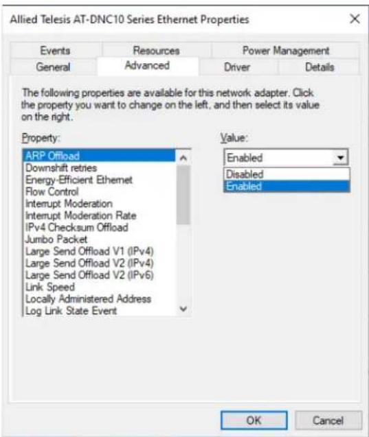
Figure 23. ARP Offload Page
- Select one of the following options:
□ Disabled — This feature is disabled.
☐ Enabled — The adapter does not wake up when responding to an ARP request. This is the default setting.
- Click OK.
Downshift Retries
This feature offers a way for the network systems to reliably select the best speed that the cabling plant can support. When `on`, it enables a link speed downgrade in case the currently selected speed is constantly failing. This only applies to DNC10T.
To specify or change the Downshift Retries feature, do the following:
- Access the Advanced Properties.
See "Accessing Advanced Properties" on page 58.
- Select Downshift Retries in the Property box.
The Downshift Retries page is displayed as shown in Figure 24.
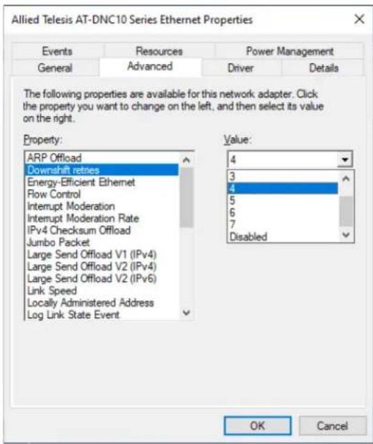
Figure 24. Downshift Retries Page
- Select one of the following options:
☐ 1 through 7 — Enables the specified amount of tries before attempting to reduce the speed.
□ Disable — This feature is disabled.
- Click OK.
Energy-Efficient Ethernet
The Energy-Efficient Ethernet property allows you to optimize the energy usage of the interface over Ethernet.
Note
This feature is valid only for copper ports.
To view the Energy-Efficient Ethernet feature, do the following:
- Access the Advanced Properties.
See "Accessing Advanced Properties" on page 58.
- Select Energy-Efficient Ethernet in the Property box.
The Energy-Efficient Ethernet page is displayed as shown in Figure 25.
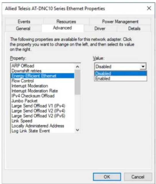
Figure 25. Energy-Efficient Ethernet Page
- Select one of the following options:
□ Disabled — For the DNC10LC and DNC10SP network adapter ports are fiber connectors and the setting is always disabled.
☐ Enabled — For the DNC10T network adapter has copper ports and can be set to Energy-Efficient Ethernet enabled.
- Click OK.
Flow Control
The Flow Control feature allows you to control the flow between the DNC10 adapter port and its link partner. You can enable or disable the adapter port to process received PAUSE frames and transmit PAUSE frames.
To specify or change the Flow Control feature, do the following:
- Access the Advanced Properties.
See "Accessing Advanced Properties" on page 58.
- Select Flow Control in the Property box.
The Flow Control page is displayed as shown in Figure 26.
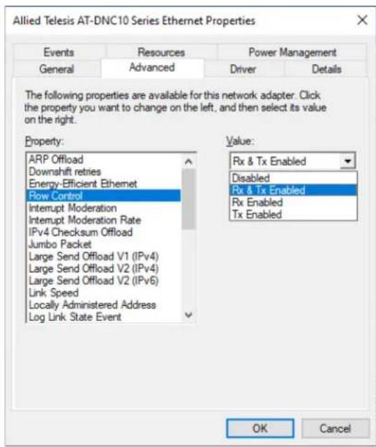
Figure 26. Flow Control Page
- Select one of the following options if available:
□ Disabled — The adapter ignores PAUSE frames.
☐ Tx & Rx Enabled — The adapter processes PAUSE frames when receiving and transmits PAUSE frames.
☐ Rx Enabled — The adapter processes PAUSE frames when receiving, but does not transmit PAUSE frame.
☐ Tx Enabled — The adapter transmits PAUSE frames, but ignores PAUSE frames when receiving.
- Click OK.
Interrupt Moderation
The Interrupt Moderation feature allows you to limit the rate of interrupts to the CPU during packet transmission and packet reception. When this feature is enabled, interrupts are handled as a group so that the CPU utilization decreases; however, the latency may increase.
To enable or disable the Interrupt Moderation feature, do the following:
- Access the Advanced Properties.
See "Accessing Advanced Properties" on page 58.
- Select Interrupt Moderation in the Property box.
The Interrupt Moderation page is displayed as shown in Figure 27.
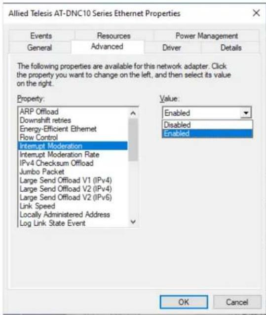
Figure 27. Interrupt Moderation Page
- Select one of the following options:
☐ Disabled — The Interrupt Moderation feature is disabled. The adapter generates one interrupt for every packet transmission and packet reception.
☐ Enabled — The Interrupt Moderation feature is enabled. This is the default setting.
- Click OK.
Interrupt Moderation Rate
To improve system performance, you can configure the interrupt moderation rate. This setting defines the maximum number of interrupts per second that the adapter is allowed to generate. Note that decreasing this value decreases the CPU usage.
To specify or change the Interrupt Moderation Rate feature, do the following:
- Access the Advanced Properties.
See "Accessing Advanced Properties" on page 58.
- Select Interrupt Moderation Rate in the Property box.
The Interrupt Moderation Rate page is displayed as shown in Figure 28.
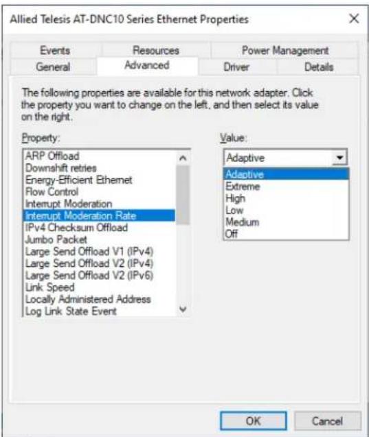
Figure 28. Interrupt Moderation Rate Page
- Select one of the following options:
☐ Adaptive — Interrupt throttle rate (ITR) = -1, no interrupts/sec, it is dynamically changed by the driver. This is the default setting.
☐ Extreme — ITR = 3600.
□ High — ITR = 2000.
☐ Medium — ITR = 950.
□ Low — ITR = 400.
☐ Off — ITR = 0, no limit.
- Click OK.
IPv4 Checksum Offload
To specify or change the IPv4 Checksum Offload feature, do the following:
- Access the Advanced Properties.
See "Accessing Advanced Properties" on page 58.
- Select IPv4 Checksum Offload in the Property box.
The IPv4 Checksum Offload page is displayed as shown in Figure 29.
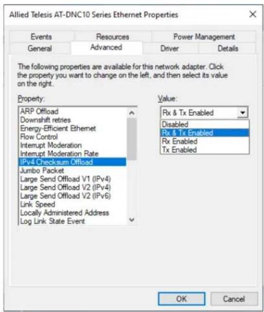
Figure 29. IPv4 Checksum Offload Page
- Select one of the following options:
□ Disabled — Disables the IPv4 Checksum Offload function for both receiving and transmitting.
☐ Rx & Tx Enabled — Enables the IPv4 Checksum Offload function for both receiving and transmitting IPv4 packets. This is the default setting.
☐ Rx Enabled — Enables the IPv4 Checksum Offload function only for receiving IPv4 packets.
☐ Tx Enabled — Enables the IPv4 Checksum Offload function only for transmitting IPv4 packets.
- Click OK.
Jumbo Packet
Enables the network adapter to transmit and receive oversized Ethernet frames that are greater than 1500 bytes, but less than or equal to 16348 bytes in length. This property requires the presence of a switch that is able to process jumbo frames. Maximum frame size is set at 1500 bytes by default (Jumbo Packet disabled). To increase the maximum frame size, choose one of the values from the drop-down list.
To change the Jumbo Packet setting, do the following:
- Access the Advanced Properties.
See "Accessing Advanced Properties" on page 58.
- Select Jumbo Packet in the Property box.
The Jumbo Packet page is displayed as shown in Figure 30.
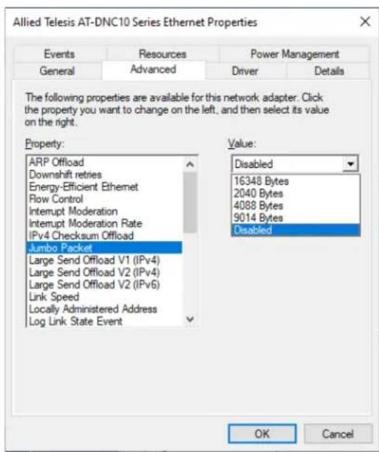
Figure 30. Jumbo Packet Page
- Select the desired jumbo frame size from the list. The options are:
□ 2040 bytes
□ 4088 bytes
□ 9014 bytes
□ 16348 bytes
☐ Disabled — The adapter does not handle jumbo frames.
- Click OK.
Large Send Offload v1 (IPv4)
Normally, the TCP segmentation is done by the protocol stack. When you enable the Large Send Offload property, the TCP segmentation can be done by the network adapter. The default setting for this property is Enabled.
To enable or disable the Large Send Offload v1 (IPv4) feature, do the following:
- Access the Advanced Properties.
See "Accessing Advanced Properties" on page 58.
- Select Large Send Offload v1 (IPv4) in the Property box.
The Large Send Offload v1 (IPv4) page is displayed as shown in Figure 31.
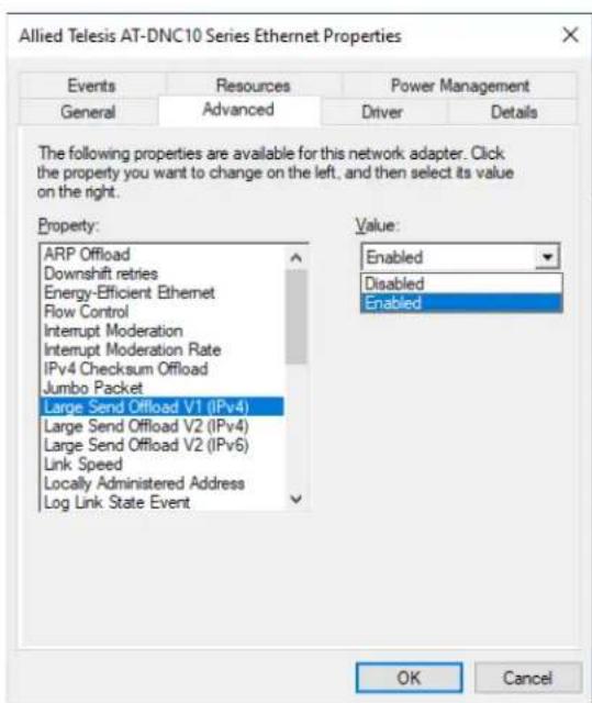
Figure 31. Large Send Offload v1 (IPv4) Page
- Select one of the following options:
□ Disabled — The Large Send Offload v1 (IPv4) feature is disabled
☐ Enabled — The Large Send Offload v1 (IPv4) feature is enabled. This is the default setting.
- Click OK.
Large Send Offload v2 (IPv4)
Normally, the TCP segmentation is done by the protocol stack. When you enable the Large Send Offload property, the TCP segmentation can be done by the network adapter. The default setting for this property is Enabled.
To enable or disable the Large Send Offload v2 (IPv4) feature, do the following:
- Access the Advanced Properties.
See "Accessing Advanced Properties" on page 58.
- Select Large Send Offload v2 (IPv4) in the Property box.
The Large Send Offload v2 (IPv4) page is displayed as shown in Figure 32.
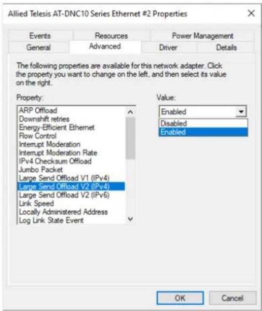
Figure 32. Large Send Offload v2 (IPv4) Page
Select one of the following options:
□ Disabled — The feature is disabled.
☐ Enabled — The adapter port segments large packets up to 256Kb for IPv4 traffic before sending them out. This is the default setting.
- Click OK.
Large Send Offload v2 (IPv6)
The Large Send Offload v2 (IPv6) feature allows you to control the load of sending out large packets. When this feature is enabled, the adapter port segments large packets for IPv6 traffic and reduces the CPU load.
To enable or disable the Large Send Offload v2 (IPv6) feature, do the following:
- Access the Advanced Properties.
See "Accessing Advanced Properties" on page 58.
- Select Large Send Offload v2 (IPv6) in the Property box.
The Large Send Offload v2 (IPv6) page is displayed as shown in Figure 33.
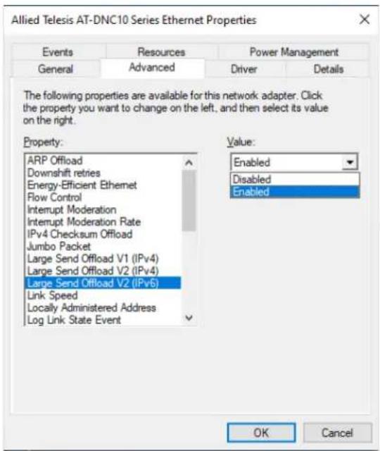
Figure 33. Large Send Offload (IPv6) Page
- Select one of the following options:
□ Disabled — The adapter does not segment packets for IPv6 traffic.
☐ Enabled — The adapter port segments large packets up to 256Kb for IPv6 traffic before sending them out. This is the default setting.
- Click OK.
Link Speed
To specify or change the port speed, do the following:
- Access the Advanced Properties.
See "Accessing Advanced Properties" on page 58.
- Select Link Speed in the Property box.
The Link Speed page is displayed as shown in Figure 34.
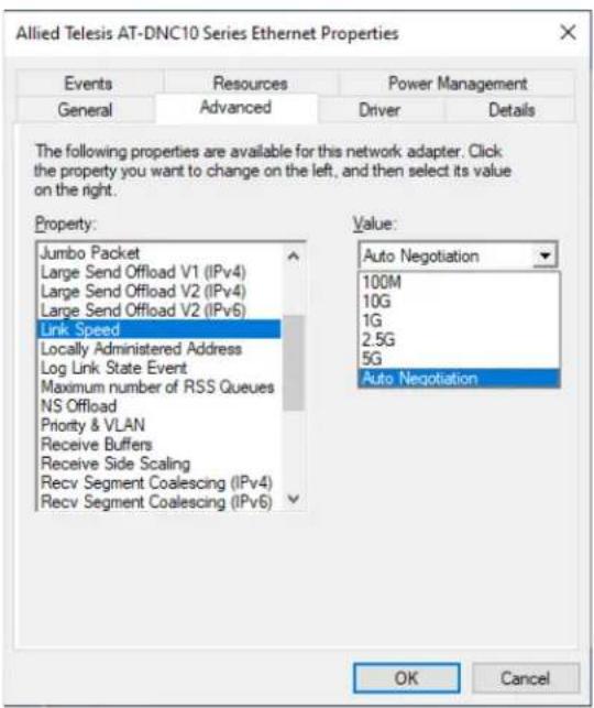
Figure 34. Link Speed Page
3. Select one of the following options:
Note
Allied Telesis recommends leaving this value set to the default Auto Negotiation. For the fiber versions of the DNC10, auto-negotiation does not refer to traditional speed and duplex auto-negotiation that is commonly used on copper-based NIC products. It simply means that the NIC will automatically detect the speed of the fiber module and set the controller's speed to match.
DNC10LC
☐ Auto Negotiation - Link speed will be set to 10G
☐ 10G - Link speed is 10G per second
All other settings are invalid.
DNC10SP
☐ Auto Negotiation - The NIC will auto-detect the SFP speed and link speed will be set to 10G or 1G accordingly
☐ 10G - Link speed is 10G per second
☐ 1G - Link speed is 1G per second
All other settings are invalid.
Note
The DNC10T uses standard auto-negotiation to determine link speed in all cases. Forced speed is disallowed by IEEE 802.3 for any speed of 1Gbps and above. When choosing a single speed from the drop-down list, only that speed will be advertised by the NIC; if the link partner does not also advertise the chosen speed, no link will be established.
DNC10T
☐ Auto Negotiation - The NIC will advertise all supported speeds and negotiate the highest common speed with the link partner.
☐ 10G - Only 10Gbps speed will be advertised.
☐ 5G - Only 5Gbps speed will be advertised.
☐ 2.5G - Only 2.5Gbps speed will be advertised.
☐ 1G - Only 1Gbps speed will be advertised.
☐ 100M - Only 100Mbps speed will be advertised.
4. Click OK.
Locally Administered Address
The Locally Administered Address is a user-defined MAC address that is used in place of the MAC address originally assigned to the network adapter. Every adapter in the network must have its own unique MAC address. This locally administered address consists of a 12-digit hexadecimal number.
To specify or change the Locally Administered Address, do the following:
- Access the Advanced Properties.
See "Accessing Advanced Properties" on page 58.
- Select Locally Administered Address in the Property box.
The Locally Administered Address page is displayed as shown in Figure 35.
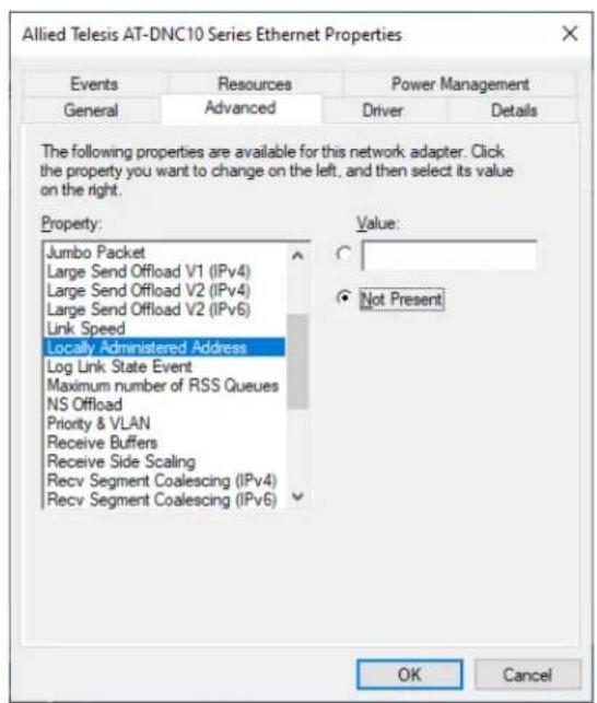
Figure 35. Locally Administered Address Page
- Select one of the following options:
☐ Value — Used to manually assign a MAC address to the adapter.
☐ Not Present — Uses the factory-assigned address on the adapter. This is the default.
Note
The appropriate assigned ranges and exceptions for the locally administered address include the following:
The range is 00:00:00:00:00:01 to FF:FF:FF:FF:FF:FD.
Do not use a multicast address (least significant bit of the high byte = 1).
Do not use all 0s or all Fs.
- Click OK.
Log Link State Event
This feature allows you to enable or disable logging of the adapter's link state changes (such as changes to the port link state or duplex mode mismatch) in the system logs.
To enable or disable the Log Link State Event feature, do the following:
- Access the Advanced Properties.
See "Accessing Advanced Properties" on page 58.
- Select Log Link State Event in the Property box.
The Log Link State Event page is displayed as shown in Figure 36.
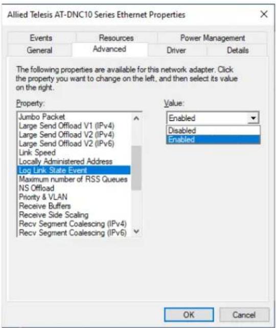
Figure 36. Log Link State Event Page
- Select one of the following options:
□ Disabled — This feature is disabled.
☐ Enabled — The adapter generates link state events. This is the default setting.
- Click OK.
Maximum Number of RSS Queues
The RSS Queues feature assigns data to queues associated with physical CPU cores. You can specify the maximum number of RSS queues that the network adapter assigns receiving data to.
To specify or change the maximum number of RSS Queues, do the following:
- Access the Advanced Properties.
See "Accessing Advanced Properties" on page 58.
- Select Maximum Number of RSS Queues in the Property box.
The Maximum Number of RSS Queues page is displayed as shown in Figure 37.
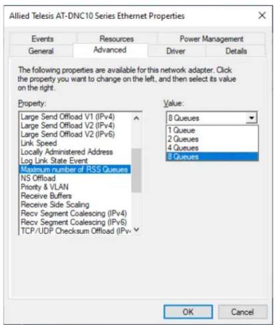
Figure 37. Maximum Number of RSS Queues Page
- Select one of the following options:
☐ 1 Queue — The system allocates up to one RSS queue.
☐ 2 Queues — The system allocates up to two RSS queues.
☐ 4 Queues — The system allocates up to four RSS queues.
☐ 8 Queues — The system allocates up to eight RSS queues.
- Click OK.
NS Offload
The NS (Neighbor Solicitation) Offload feature enables the adapter not to wake up when responding to an NS request.
To enable or disable the NS Offload feature, do the following:
- Access the Advanced Properties.
See "Accessing Advanced Properties" on page 58.
- Select NS Offload in the Property box.
The NS Offload page is displayed as shown in Figure 38.
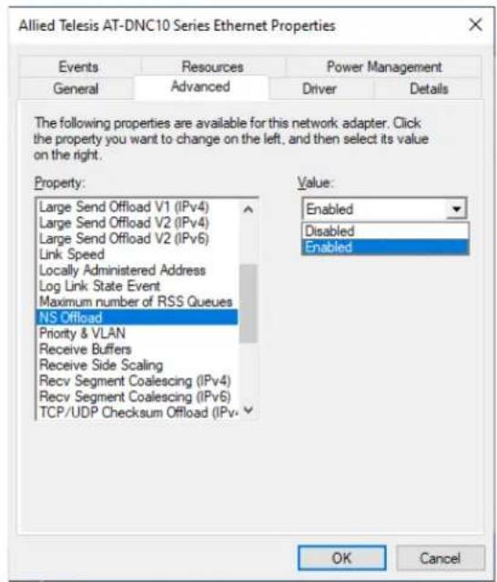
Figure 38. NS Offload Page
- Select one of the following options:
□ Disabled — This feature is disabled.
☐ Enabled — The adapter does not wake up when responding to an NS request. This is the default setting.
- Click OK.
The Priority & VLAN feature allows you to control sending and receiving tagged frames of QoS and VLAN.
When the property is set to Priority & VLAN Enabled, the adapter sends and receives QoS and VLAN tagged frames; with Priority Enabled, the adapter sends and receives QoS tagged frames; with VLAN Enabled, the adapter sends and receives VLAN tagged frames. To assign a VLAN ID to the adapter, see "VLAN ID" on page 94.
To enable or disable the Priority & VLAN feature, do the following:
- Access the Advanced Properties.
See "Accessing Advanced Properties" on page 58.
- Select Priority & VLAN in the Property box.
The Priority & VLAN page is displayed as shown in Figure 39.
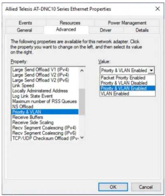
Figure 39. Priority & VLAN Page
- Select one of the following options:
☐ Priority & VLAN Enabled — Allows for packet prioritization and VLAN tagging. This is the default setting.
☐ Priority & VLAN Disabled — Prevents packet prioritization and VLAN tagging.
☐ Packet Priority Enabled — Allows packet prioritization only.
☐ VLAN Enabled — Allows VLAN tagging only.
- Click OK.
Receive Buffers
Receive buffers are data segments that allow the network adapter to allocate receive packets to memory.
To specify or change the Receive Buffers feature, do the following:
- Access the Advanced Properties.
See "Accessing Advanced Properties" on page 58.
- Select Receive Buffers in the Property box.
The Receive Buffers page is displayed as shown in Figure 40.
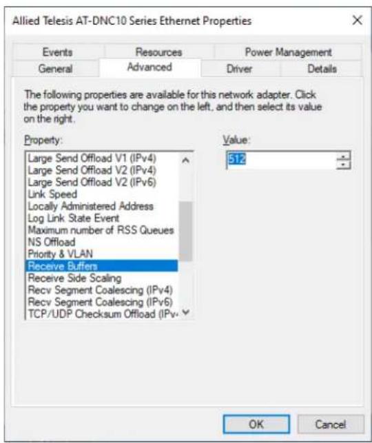
Figure 40. Receive Buffers Page
- Specify the buffer size in the Value box.
The range of valid receive buffers is 128 to 4096 in increments of 8 with 512 receive buffers as the default value.
- Click OK.
Receive Side Scaling
The Receive Side Scaling (RSS) feature allows the adapter to efficiently distribute receive processing across multiple CPU's so as to prevent overloading a single CPU. To make this feature effective, the computer must have multiple CPU's in a multiprocessor system.
To enable or disable the Receive Side Scaling feature, do the following:
- Access the Advanced Properties.
See "Accessing Advanced Properties" on page 58.
- Select Receive Side Scaling in the Property box.
The Receive Side Scaling page is displayed as shown in Figure 41.
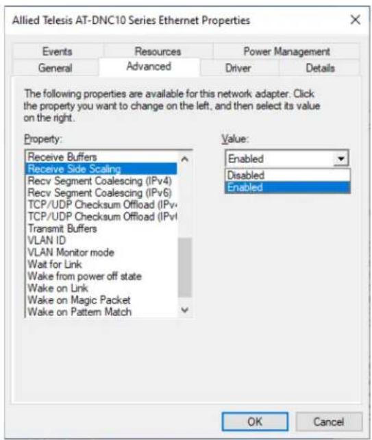
Figure 41. Receive Side Scaling Page
- Select one of the following options:
☐ Enabled — Receiving data is processed by multiple CPU's. This is the default setting.
□ Disabled — Receiving data is processed by a single CPU.
- Click OK.
Recv Segment Coalescing (IPv4)
When receiving data, the miniport driver, NDIS, and TCP/IP must all look at each segment's header information separately. When large amounts of data are being received, this creates a large amount of overhead. Receive segment coalescing (RSC) reduces this overhead by coalescing a sequence of received segments and passing them to the host TCP/IP stack in one operation, so that NDIS and TCP/IP need only look at one header for the entire sequence.
To enable or disable the Receive Segment Coalescing (IPv4) feature, do the following:
- Access the Advanced Properties.
See "Accessing Advanced Properties" on page 58.
- Select Receive Segment Coalescing (IPv4) in the Property box.
The Receive Segment Coalescing (IPv4) page is displayed as shown in Figure 42.
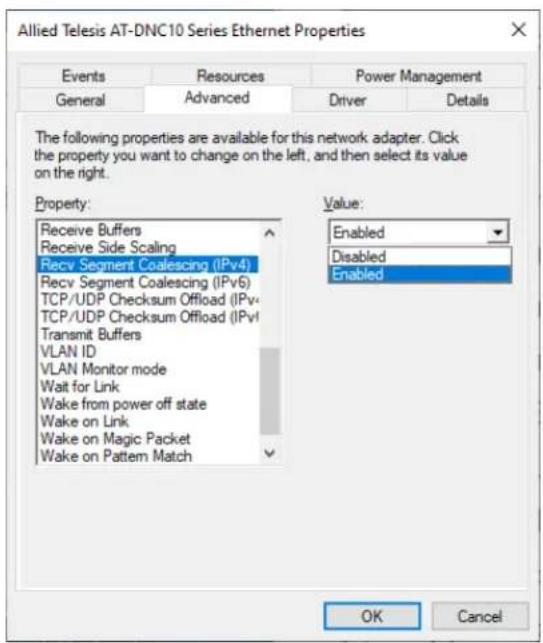
Figure 42. Receive Segment Coalescing (IPv4) Page
- Select one of the following options:
☐ Enabled — RSC is enabled. This is the default setting.
□ Disabled — RSC is disabled.
- Click OK.
Recv Segment Coalescing (IPv6)
When receiving data, the miniport driver, NDIS, and TCP/IP must all look at each segment's header information separately. When large amounts of data are being received, this creates a large amount of overhead. Receive segment coalescing (RSC) reduces this overhead by coalescing a sequence of received segments and passing them to the host TCP/IP stack in one operation, so that NDIS and TCP/IP need only look at one header for the entire sequence.
To enable or disable the Receive Segment Coalescing (IPv6) feature, do the following:
- Access the Advanced Properties.
See "Accessing Advanced Properties" on page 58.
- Select Receive Segment Coalescing (IPv6) in the Property box.
The Receive Segment Coalescing (IPv6) page is displayed as shown in Figure 43.
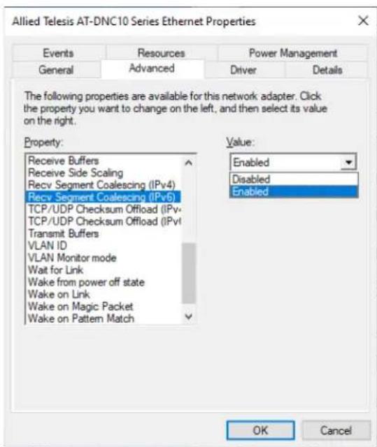
Figure 43. Receive Segment Coalescing (IPv6) Page
- Select one of the following options:
☐ Enabled — RSC is enabled. This is the default setting.
□ Disabled — RSC is disabled.
- Click OK.
TCP/UDP Checksum Offload (IPv4)
The TCP/UDP Checksum Offload (IPv4) function enables the adapter port to compute the checksum of transmitting IPv4 packets and verify the checksum of receiving IPv4 packets, taking load off from the CPU.
To modify the TCP/UDP Checksum Offload (IPv4) setting, do the following:
- Access the Device Manager on your operating system.
See "Accessing Advanced Properties" on page 58.
- Select TCP/UDP Checksum Offload (IPv4) in the Property box.
The TCP/UDP Checksum Offload (IPv4) page is displayed as shown in Figure 44.
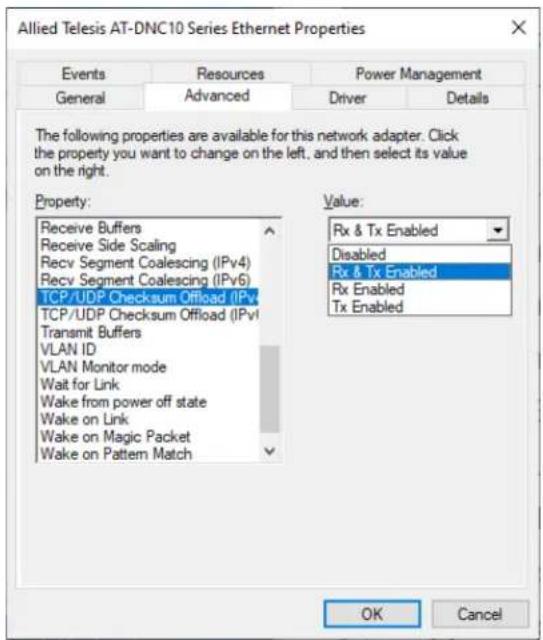
Figure 44. TCP/UDP Checksum Offload (IPv4) Page
- Select one of the following options:
☐ Rx & Tx Enabled — Enables the TCP/UDP Checksum Offload (IPv4) function for both receiving and transmitting IPv4 packets. This is the default setting.
□ Disabled — Disables the TCP/UDP Checksum Offload (IPv4) function for both receiving and transmitting.
☐ Rx Enabled — Enables the TCP/UDP Checksum
Offload (IPv4) function only for receiving IPv4 packets.
☐ Tx Enabled — Enables the TCP/UDP Checksum Offload (IPv4) function only for transmitting IPv4 packets.
- Click OK.
TCP/UDP Checksum Offload (IPv6)
The TCP/UDP Checksum Offload (IPv6) function enables the adapter port to compute the checksum of transmitting IPv6 packets and verify the checksum of receiving IPv6 packets, taking load off from the CPU.
To enable or disable the TCP/UDP Checksum Offload (IPv6) feature, do the following:
- Access the Device Manager on your operating system.
See "Accessing Advanced Properties" on page 58.
- Select TCP/UDP Checksum Offload (IPv6) in the Property box.
The TCP/UDP Checksum Offload (IPv6) page is displayed as shown in Figure 45.
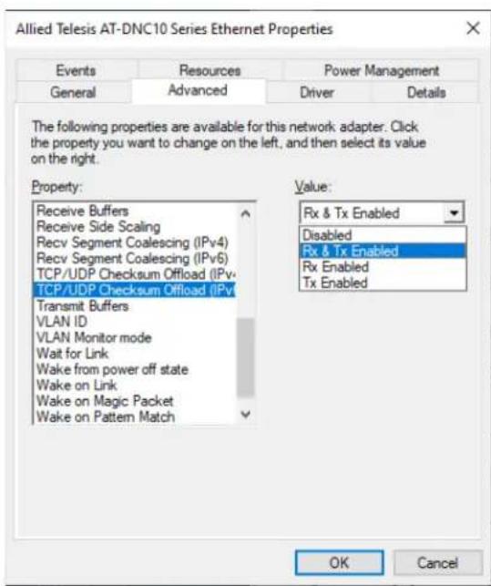
Figure 45. TCP/UDP Checksum Offload (IPv6) Page
- Select one of the following options:
☐ Rx & Tx Enabled — Enables the TCP/UDP Checksum Offload (IPv6) function for both receiving and transmitting IPv6 packets. This is the default setting.
□ Disabled — Disables the TCP/UDP Checksum Offload (IPv6) function for both receiving and transmitting.
☐ Rx Enabled — Enables the TCP/UDP Checksum
Offload (IPv6) function only for receiving IPv6 packets.
☐ Tx Enabled — Enables the TCP/UDP Checksum Offload (IPv6) function only for transmitting IPv6 packets.
- Click OK.
Transmit Buffers
The number of transmit buffers. Transmit buffers are data segments that allow the network adapter to monitor transmit packets in the system memory.
To specify or change the Transmit Buffers feature, do the following:
- Access the Device Manager on your operating system.
See "Accessing Advanced Properties" on page 58.
- Select Transmit Buffers in the Property box.
The Transmit Buffers page is displayed as shown in Figure 46.
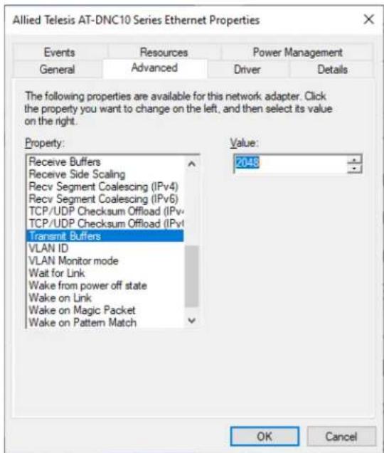
Figure 46. Transmit Buffers Page
-
Specify the buffer size in the Value box. The valid range is 256 to 8184 in increments of 8. The default value is 2048
-
Click OK.
VLAN ID
The VLAN ID property allows you to specify a VLAN ID on your network to the adapter port. The adapter port adds the value of the VLAN ID to a frame in the VLAN tag before transmitting the frame.
To change the VLAN ID value, do the following:
- Access the Advanced Properties.
See "Accessing Advanced Properties" on page 58.
- Select VLAN ID in the Property box.
The VLAN ID page is displayed as shown in Figure 47.
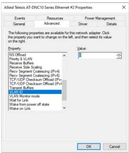
Figure 47. VLAN ID Page
- Specify a VLAN ID in the Value box.
The range of the value is from 0 to 4094. The default value is 0. Leaving the VLAN ID set to 0 will result in no VLAN tag being added to egress packets, even if VLAN is enabled. This field must be set to the desired VLAN ID if VLAN headers are desired.
- Click OK.
- Installation and User's Guide
- Federal Communications Commission Interference Statement
- Declaration of Conformity
- IMPORTANT NOTE:
- FCC Radiation Exposure Statement:
- Industry Canada
- European Union Restriction of the Use of Certain Hazardous Substances (RoHS) in Electrical and Electronic Equipment
- Chapter 1: Introduction ...... 17
- Chapter 2: Installing the Hardware ....27
- Chapter 3: Installing the Driver Software ....41
- Chapter 4: Modifying Advanced Properties ....55
- Contents
- Tables
- Figures
- List of Figures
- Safety Symbols Used in this Document
- Note
- Caution
- Warning
- Contacting Allied Telesis
- Functional Description
- DNC10LC Fiber Optic Port
- DNC10T Twisted Pair Copper Port
- Features
- Hardware □ DNC10SP supports one SFP+ port
- Software □ Windows 10, 64-bit
- Chapter 2
- Installing the Hardware
- System Requirements
- Reviewing Safety Precautions
- Pre-Installation Checklist
- Replacing the Bracket
- Installing a Network Adapter
- Power the system on.
- Connecting the Network Cable
- DNC10LC Fiber Optic Cable
- DNC10SP SFP+ Transceiver
- DNC10T Twisted-Pair Copper Cable
- Chapter 3
- Installing the Driver Software
- Overview
- Guidelines
- Installing the Driver Using the Device Manager
- Installing the Driver Using the Silent Installation Method
- Downloading the Driver Software
- Accessing the Device Manager
- Option 1
- Option 2
- c. Select Browse my computer for driver software.
- Updating the Driver Software
- Performing the Silent Installation
- Installing the Driver Silently
- Viewing Supported DPInst Options
- This chapter includes the following topics:
- Accessing Advanced Properties
- ARP Offload
- Downshift Retries
- Energy-Efficient Ethernet
- Flow Control
- Interrupt Moderation
- Interrupt Moderation Rate
- IPv4 Checksum Offload
- Jumbo Packet
- Large Send Offload v1 (IPv4)
- Large Send Offload v2 (IPv4)
- Large Send Offload v2 (IPv6)
- Link Speed
- Select one of the following options:
- DNC10LC
- DNC10SP
- DNC10T
- Click OK.
- Locally Administered Address
- Log Link State Event
- Maximum Number of RSS Queues
- NS Offload
- Receive Buffers
- Receive Side Scaling
- Recv Segment Coalescing (IPv4)
- Recv Segment Coalescing (IPv6)
- TCP/UDP Checksum Offload (IPv4)
- TCP/UDP Checksum Offload (IPv6)
- Transmit Buffers
- VLAN ID
Brand : Allied Telesis
Model : DNC10LC
Category : Carte réseau/Adaptateur