2914SP - Network Card/Adapter Allied Telesis - Free user manual and instructions
Find the device manual for free 2914SP Allied Telesis in PDF.


| Product Type | Network Interface Card (NIC) |
| Model | AT-2914SP |
| Host Interface | PCI Express x1 (v2.0) |
| Network Interface | 1x RJ-45 10/100/1000 Mbps Ethernet |
| Standards | IEEE 802.3, 802.3u, 802.3ab |
| Data Rate | 10/100/1000 Mbps (auto-negotiation) |
| MAC Address | Built-in, 48-bit |
| Jumbo Frame Support | Up to 9216 bytes |
| Wake-on-LAN | Supported (WoL) |
| LED Indicators | Link/Activity, Speed (1000, 100) |
| Dimensions (W x D x H) | 120 x 80 x 20 mm (5.12 x 3.15 x 0.79 in) |
| Weight | ~85 g (3.0 oz) |
| Power Consumption | < 3 W (typical) |
| Operating Temperature | 0°C to 40°C (32°F to 104°F) |
| Storage Temperature | -20°C to 70°C (-4°F to 158°F) |
| Humidity | 10% to 90% (non-condensing) |
| Certifications | CE, FCC Class B |
| Operating System Support | Windows 10/11, Linux, macOS (driver dependent) |
| Included Accessories | Low-profile bracket, installation guide |
| Warranty | Limited Lifetime |
Frequently Asked Questions - 2914SP Allied Telesis
User questions about 2914SP Allied Telesis
0 question about this device. Answer the ones you know or ask your own.
Ask a new question about this device
Download the instructions for your Network Card/Adapter in PDF format for free! Find your manual 2914SP - Allied Telesis and take your electronic device back in hand. On this page are published all the documents necessary for the use of your device. 2914SP by Allied Telesis.
USER MANUAL 2914SP Allied Telesis
Fiber Network Adapters with Wake on LAN (WoL)
AT-2914SX/SC
AT-2914SX/LC
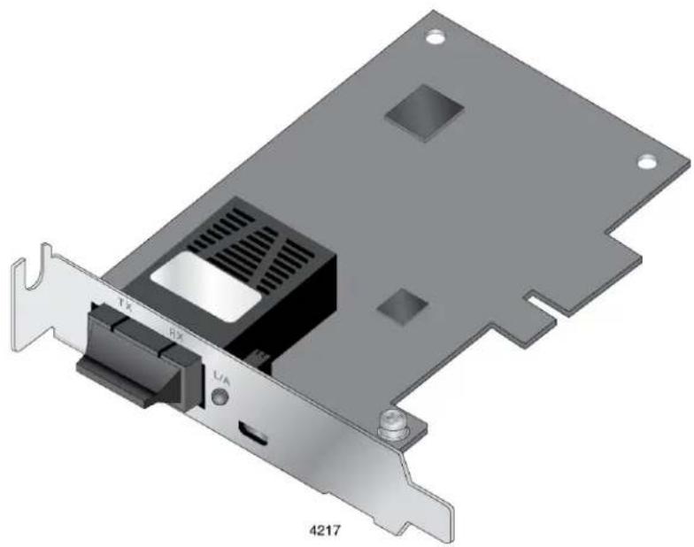
AT-2914SP
natural_image
3D diagram of a computer drive card with labeled ports (TX, RX, L/A) and part number 4217, no readable text or symbols beyond labels.Installation and User's Guide
the solution : the network
613-002358 Rev. A
Copyright © 2017 Allied Telesis, Inc.
All rights reserved. No part of this publication may be reproduced without prior written permission from Allied Telesis, Inc. Microsoft and Internet Explorer are registered trademarks of Microsoft Corporation. Netscape Navigator is a registered trademark of Netscape Communications Corporation. All other product names, company names, logos or other designations mentioned herein are trademarks or registered trademarks of their respective owners.
Allied Telesis, Inc. reserves the right to make changes in specifications and other information contained in this document without prior written notice. The information provided herein is subject to change without notice. In no event shall Allied Telesis, Inc. be liable for any incidental, special, indirect, or consequential damages whatsoever, including but not limited to lost profits, arising out of or related to this manual or the information contained herein, even if Allied Telesis, Inc. has been advised of, known, or should have known, the possibility of such damages.
Electrical Safety and Emissions Standards
This product meets the following standards:
Federal Communications Commission Interference Statement
Declaration of Conformity
Manufacturer Name: Allied Telesis, Inc.
Declares that the product: Fiber Network Adapter with WoL
Model Number: AT-2914SX/SC, AT-2914SX/LC, AT-2914SP
This device complies with Part 15 of the FCC Rules. Operation is subject to the following two conditions: (1) This device may not cause harmful interference, and (2) this device must accept any interference received, including interference that may cause undesired operation.
This equipment has been tested and found to comply with the limits for a Class B digital device, pursuant to Part 15 of the FCC Rules. These limits are designed to provide reasonable protection against harmful interference in a residential installation. This equipment generates, uses and can radiate radio frequency energy and, if not installed and used in accordance with the instructions, may cause harmful interference to radio communications. However, there is no guarantee that interference will not occur in a particular installation. If this equipment does cause harmful interference to radio or television reception, which can be determined by turning the equipment off and on, the user is encouraged to try to correct the interference by one of the following measures:
☐ Reorient or relocate the receiving antenna.
☐ Increase the separation between the equipment and receiver.
☐ Connect the equipment into an outlet on a circuit different from that to which the receiver is connected.
Consult the dealer or an experienced radio/TV technician for help.

Caution
Any changes or modifications not expressly approved by the party responsible for compliance could void the user's authority to operate this equipment. E80

Avertissement
This transmitter must not be co-located or operating in conjunction with any other antenna or transmitter.
The band from 5600-5650MHz will be disabled by the software during the manufacturing and cannot be changed by the end user. This device meets all the other requirements specified in Part 15E, Section 15.407 of the FCC Rules.
Radiation Exposure Statement:
This equipment complies with FCC radiation exposure limits set forth for an uncontrolled environment. This equipment should be installed and operated with minimum distance 20cm between the radiator & your body.
European Union Restriction of the Use of Certain Hazardous Substances (RoHS) in Electrical and Electronic Equipment
This Allied Telesis RoHS-compliant product conforms to the European Union Restriction of the Use of Certain Hazardous Substances (RoHS) in Electrical and Electronic Equipment. Allied Telesis ensures RoHS conformance by requiring supplier Declarations of Conformity, monitoring incoming materials, and maintaining manufacturing process controls.
Note
For additional regulatory statements, refer to Appendix B, "Regulatory Statements" on page 93.
Safety and Electromagnetic Emissions Certificates
Standard Compliance
□ RoHs compliant
☐ European Union RoHS (Directive 2011/65/EU of the European Parliament and of the Council of 8 June 2011 on the restriction of the use of certain hazardous substances in electrical and electronic equipment.)
Certificates
□ CE
□ VCCI Class B
□ C-TICK
Electromagnetic Compatibility (EMC)
□ VCCI Class B
□ C-TICK
Radio Equipment
□ EN55032 Class B
□ EN55035 Class B
□ FCC Class B
Safety
□ UL1950
□ CSA22.2 No.950
Translated Safety Statements
Important: The indicates that a translation of the safety statement is available in a PDF document titled "Translated Safety Statements" on the Allied Telesis website at www.alliedtelesis.com/support.
Contents
Preface 9
Safety Symbols Used in this Document....10
Contacting Allied Telesis 11
Chapter 1: Introduction ...... 13
Description....14
2914 Series Network Adapter Models....15
SC Optical Fiber Connector....15
LC Fiber Optic Adapter....15
SFP Slot 15
LED 16
Model Naming Conventions....17
Supported Operating Systems 18
Accessing Documents 19
Allied Telesis Documents....19
Contents of Your Shipment 20
Warranty Registration....21
Chapter 2: Installing the Hardware ....23
System Requirements 24
Reviewing Safety Precautions....25
Pre-Installation Checklist 27
Replacing the Bracket 28
Installing a Network Adapter....30
Connecting the Network Cables 34
Connecting a Fiber Optic Network Cable 34
Connecting an SFP Transceiver....34
Chapter 3: Installing the Driver Software ....37
Overview....38
Guidelines 38
Installing the Driver Using Device Manager 38
Installing the Driver Using the Silent Installation Method ....38
Downloading the Driver Software 39
Accessing Device Manager 41
Accessing Device Manager on Windows 8 and Windows 10....41
Accessing Device Manager on Windows 7 41
Installing the Driver Software....42
Updating the Driver Software....45
Performing the Silent Installation....46
Installing the Driver Silently 46
Viewing Supported DPInst Options 47
Chapter 4: Modifying Advanced Properties ....49
Overview....50
Guidelines 50
Accessing Advanced Properties 51
802.3az EEE....52
ARP Offload....53
Ethernet@WireSpeed....54
Flow Control 55
Interrupt Moderation ....57
Jumbo Mtu 58
Large Send Offload v2 (IPv4) 59
Large Send Offload v2 (IPv6) 61
Maximum Number of RSS Queues....62
Network Address....64
NS Offload 66
Priority & VLAN 67
Receive Side Scaling....69
Speed & Duplex....70
TCP/UDP Checksum Offload (IPv4)....72
TCP/UDP Checksum Offload (IPv6)....74
VLAN ID 76
Wake on Magic Packet....77
Wake on Pattern Match 78
WOL Speed 79
Chapter 5: Uninstalling the Driver Software ....81
Overview 82
Guidelines....82
Uninstalling the Driver Software Using Device Manager 83
Uninstalling the Driver Software Silently 84
Chapter 6: Troubleshooting ....85
Checking the Port LED on the Adapter....86
Troubleshooting Checklist....87
Testing Network Connectivity 88
Windows 88
Linux 89
Appendix A: Specifications 91
Physical Specifications 91
Environmental Specifications....91
Power Specifications....91
Optical Specifications....91
SX....91
LX 91
Appendix B: Regulatory Statements 93
Federal Communication Commission Interference Statement 94
Radiation Exposure Statement....95
Country Code Selection (WiFi Devices) 95
Industry Canada Statement 96
Caution: 96
Avertissement: 96
Radiation Exposure Statement: 97
Professional Installation Instruction: 97
Europe - EU Declaration of Conformity....99
Europe – EU Declaration of Conformity....99
Appendix C: Cleaning Fiber Optic Connectors 103
Overview....104
Guidelines....104
Cleaning Using a Cartridge-Type Cleaner....105
Cleaning Using a Swab....107
This manual is the installation and user's guide for the 2914 Series Fiber Network Adapters with WoL. The network adapters included in this series are:
The Preface contains the following sections:
☐ "Safety Symbols Used in this Document" on page 10
☐ "Contacting Allied Telesis" on page 11
Safety Symbols Used in this Document
This document uses the following conventions:
Note
Notes provide additional information.

Caution
Cautions inform you that performing or omitting a specific action may result in equipment damage or loss of data.

Warning
Warnings inform you that performing or omitting a specific action may result in bodily injury.

Warning
Warnings inform you that an eye and skin hazard exists due to the presence of a Class 1 laser device.
If you need assistance with this product, you may contact Allied Telesis technical support by going to the Support & Services section of the Allied Telesis web site at www.alliedtelesis.com/support. You can find links for the following services on this page:
☐ 24/7 Online Support - Enter our interactive support center to search for answers to your questions in our knowledge database, check support tickets, learn about Return Merchandise Authorization (RMA), and contact Allied Telesis technical experts.
☐ USA and EMEA phone support - Select the phone number that best fits your location and customer type.
□ Hardware warranty information - Learn about Allied Telesis warranties and register your product online.
□ Replacement Services - Submit an RMA request via our interactive support center.
□ Documentation - View the most recent installation guides, user guides, software release notes, white papers and data sheets for your product.
☐ Software Updates - Download the latest software releases for your product.
For sales or corporate contact information, go to www.alliedtelesis.com/purchase and select your region.
This chapter provides an introduction to the 2914 Series Fiber Network Adapters with WoL.
This chapter contains the following sections:
☐ "Description" on page 14
☐ “Model Naming Conventions” on page 17
☐ “Supported Operating Systems” on page 18
☐ “Accessing Documents” on page 19
☐ "Contents of Your Shipment" on page 20
☐ "Warranty Registration" on page 21
Description
The 2914 series fiber network adapters are 100/1000Mb Ethernet PCI Express (PCIe) cards developed based on a Marvell 88E6320 switch chip and Broadcom's BCM57762 network controller. The 2914 series network adapter is equipped with one fiber optic port or SFP slot and supports the Wak-on-LAN (WoL) feature.
The AT-2914SX/SC and AT-2914SX/LC models are Gigabit Ethernet network adapters operating at 1000Mbs; the AT-2914SP model can operate at 100 Mbs or 1000 Mbs depending on the SFP type in use.
Wake-on-LAN (WoL) is a protocol for remotely turning on a computer in a low power mode with a network message. A magic packet is a network message that a WoL-enabled computer receives and wakes up when the computer's MAC address matches one in the magic packet.
After physically installing the 2914 series network adapters on your Windows operating system, you must install driver software. To install driver software, see Chapter 3, "Installing the Driver Software" on page 37.
Note
You do not need to install driver software for Linux system because Linux has inbox drivers for the 2914 series network adapters.
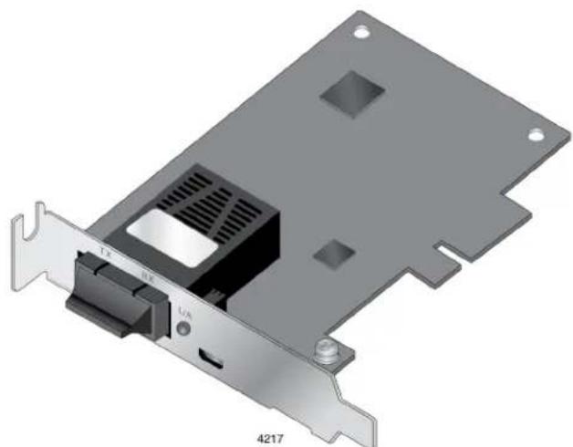
Figure 1 shows the AT-2914SX/SC model.
natural_image
3D diagram of a computer drive card showing internal components and mounting bracket (no text or symbols)Figure 1. AT-2914 Network Adapter
2914 Series Network Adapter Models
The AT-2914 series includes the following models:
SC Optical Fiber Connector
The AT-2914SX/SC network adapter is equipped with a 1000BASE-SX port with the SC connector.
The SC connector is shown in Figure 2.
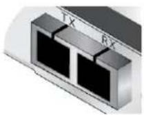
Figure 2. SC Optical Fiber Connector
To connect the SC optical fiber connector to a network cable, you must have a fiber optic network cable with the SC connector.
LC Fiber Optic Adapter
The AT-2914SX/LC network adapter is equipped with a 1000BASE-SX port with the LC connector.
The LC connector is shown in Figure 3.
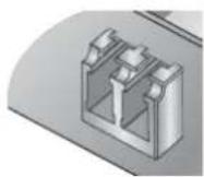
Figure 3. LC Optical Fiber Connector
SFP Slot The AT-2914SP network adapter has an SFP slot that you can plug in an SFP transceiver to connect the network adapter to a compatible link partner. The link connected through the SFP slot operates at either 100Mbps or 1000Mbps (depending upon the speed of the installed SFP) and only in full-duplex mode.
Note
An SFP transceiver must be purchased separately. For a list of supported transceivers, contact your Allied Telesis distributor or reseller.
The SFP slot is shown in Figure 4.
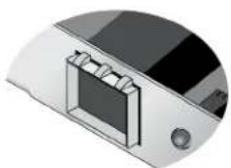
Figure 4. SFP Slot
LED The 2914 series network adapters come with one LED as shown in Figure 5. The LED indicates the link and activity status of the port.
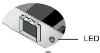
Figure 5. LED's on the Copper Port
Table 1 describes the link states that the LED indicates.
Table 1. LED Status
| State Description | |
| On Valid link. | |
| Off No link. | |
| Flashing The | port is receiving or transmitting network packets. |
Model Naming Conventions
The hardware features of the 2914 series network adapters are represented by the letters and numbers in the model names. The conventions for the 2914 series network adapters are identified in Figure 6.
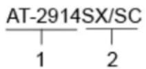
Figure 6. 2914 Series Model Naming Conventions
The conventions are defined in Table 2.
Table 2. 2914 Series Model Naming Conventions
| Convention | Definition |
| 1 Indicates the product name | |
| 2 Identifies the type of the port. The following is a list of options:☐ SX/SC - port of 1000BASE-SX (short haul) fiber optic cable with an SC connector☐ SX/LC - port of 1000BASE-SX (short haul) fiber optic cable with an LC connector☐ SP - SFP slot | |
Supported Operating Systems
The following list shows the supported operating systems:
☐ Windows 10 in 32-bit and 64-bit; Microsoft certified
☐ Windows 8/8.1 in 32-bit and 64-bit; Microsoft certified
☐ Windows 7 in 32-bit and 64-bit; Microsoft certified
□ Linux 2.6
The 2914 series network adapter that is installed on Linux systems uses Linux inbox driver software to operate so that you do not need to install driver software for Linux systems. A driver supplied with an operating system is called an inbox driver.
For Windows Operating Systems, you must install driver software for the 2914 series network adapter. To install driver software for Windows Operating Systems, see Chapter 3, "Installing the Driver Software" on page 37.
Accessing Documents
Allied Telesis Documents
Documents for the 2914 series network adapters are available at Allied Telesis websites.
To access documents for 2914 series network adapters, do the following:
- Open a web browser, such as Internet Explorer or FireFox, on your system and enter the following:
http://www.alliedtelesis.com/
The Allied Telesis home page is displayed.
-
Enter "2914" in the search box and press the enter key.
-
Click "2914" from the search results.
The 2914 series product page is displayed.
- Click one of the listed documents.
The content of the document is displayed.
Contents of Your Shipment
The following items are Included with your network adapter:
□ Antistatic bag
The network adapter is shipped in an antistatic bag. It protects the network adapter when stored or shipped. Keep the network adapter in its packaging until ready for installation.
☐ Standard-profile bracket
The standard-profile bracket is longer than the low-profile bracket. The 2914 series network adapters are shipped with a low-profile bracket attached.
Note
The 2914 series network adapter is not shipped with a software driver CD. You must download the driver software for Windows from the Allied Telesis website. See Chapter 3, "Downloading the Driver Software" on page 39.
Inform your network equipment supplier of any missing or damaged items. If you need to return the module, you must pack it in the original (or equivalent) packing material or the warranty will be voided. See "Contacting Allied Telesis" on page 11.
Warranty Registration
Allied Telesis hardware products are covered under limited warranties.
All Allied Telesis warranties are subject to and provided only on the terms and conditions set out in the Allied Telesis Limited Warranties listed on the Allied Telesis website at http://alliedtelesis.com/support/warranty.
Chapter 2
Installing the Hardware
This chapter contains the following sections:
☐ "System Requirements" on page 24
☐ “Reviewing Safety Precautions” on page 25
☐ "Pre-Installation Checklist" on page 27
☐ "Replacing the Bracket" on page 28
☐ "Installing a Network Adapter" on page 30
☐ “Connecting the Network Cables” on page 34
System Requirements
Before installing the 2914 series network adapter, make sure your system meets the requirements listed below:
☐ PC with one of the following operating systems installed:
- Windows 10 in 32-bit or 64-bit; Microsoft certified
- Windows 8/8.1 in 32-bit or 64-bit; Microsoft certified
- Windows 7 in 32-bit or 64-bit; Microsoft certified
- Linux 2.6
☐ One open PCIe slot
☐ 128 MB RAM (minimum)
Reviewing Safety Precautions
Review the following safety precautions before you begin to install a network adapter.
Note
The ^60 indicates that a translation of the safety statement is available in a PDF document titled “Translated Safety Statements” posted on the Allied Telesis website at www.alliedtelesis.com/support/software/.

Warning
Do not stare into the laser beam. L2

Warning
The fiber optic ports contain a Class 1 laser device. When the ports are disconnected, always cover them with the provided plug. Exposed ports may cause skin or eye damage. L4

Warning
Do not look directly at the fiber optic cable ends or inspect the cable ends with an optical lens. L6

Warning
Do not work on this equipment or cables during periods of lightning activity. E2

Warning
Operating Temperature: This product is designed for a maximum ambient temperature of 40 degrees C. √ E7
Note
All Countries: Install this product in accordance with local and National Electric Codes. E8

Warning
The module is being installed in a system that operates with voltages that can be lethal. Before you remove the cover of your system, you must observe the following precautions to protect yourself and to prevent damage to the system components.
- Remove any metallic objects or jewelry from your hands and wrists.
- Make sure to use only insulated or nonconducting tools.
- Verify that the system is powered OFF and unplugged before accessing internal components.
- Installation or removal of modules must be performed in a static-free environment. The use of a properly grounded wrist strap or other personal antistatic devices and an antistatic mat is strongly recommended. E39

Caution
Do not use excessive force when seating the card, as the force may damage the system or the adapter card. If the card resists seating, remove it from the system, realign it, and try again. E47
Pre-Installation Checklist
Before installing the 2914 series network adapter, check the following list:
- Check that your computer has an appropriate open PCIe slot.
- Check that the power supply on your computer has a SATA power connector.
- Verify that your system is using the latest BIOS.
- When you download the driver software from the Allied Telesis website, record the path to where the driver file resides on your system.
- If your system is active, shut it down.
- When system shutdown is complete, power OFF and unplug your system.
- Holding the adapter card by the edges, remove it from its shipping package and place it on an antistatic surface.
- Check the adapter for visible signs of damage, particularly on the card's edge connector.
Note
Do not attempt to install any damaged adapter card. If the adapter card is damaged, report it to Allied Telesis. See “Contacting Allied Telesis” on page 11.
Replacing the Bracket
The 2914 series network adapter is shipped with the low-profile bracket attached to the adapter. Depending on your system, you may need to replace the bracket attached to your adapter card.
The following procedure describes how to remove the low-profile bracket from the network adapter and replace it with the standard bracket. You can also use this procedure to remove the standard bracket and replace it with the low-profile bracket.
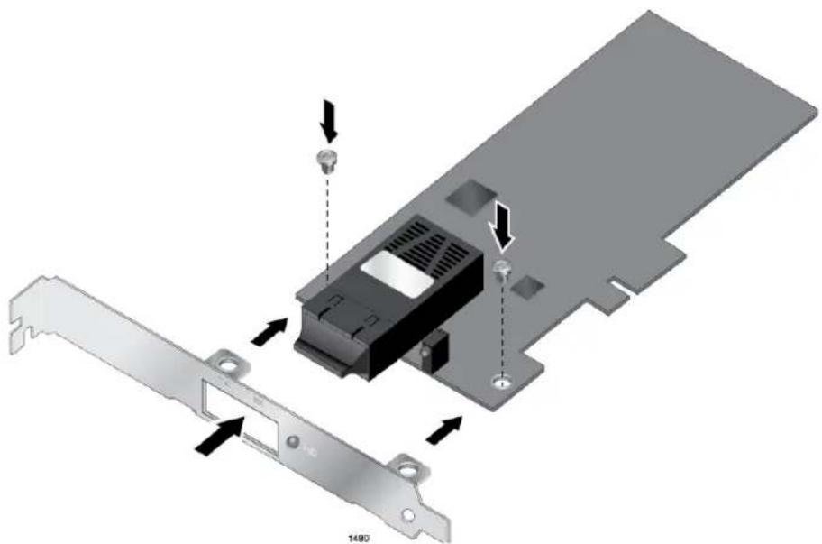
To replace the low-profile bracket with the standard bracket, perform the following procedure:
- Remove the screws that attach the bracket to the network adapter. See Figure 7.
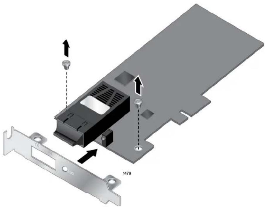
Figure 7. Removing the Low-Profile Bracket
- Align the tabs of the standard bracket with the holes on the network adapter and fasten the screws onto the network adapter. See Figure 8 on page 29.
natural_image
3D diagram of a computer hardware component with labeled parts and arrows indicating assembly (no text or symbols present)Figure 8. Fastening Screws onto Standard Bracket
Installing a Network Adapter
The following instructions apply to installing a 2914 series network adapter in most systems. Refer to the manuals that were supplied with your system for details about performing these tasks on your particular system.
To install the network adapter, perform the following procedure:
- Review the "Pre-Installation Checklist" on page 27 and "Reviewing Safety Precautions" on page 25.
Before installing the network adapter, ensure the system power is OFF and unplugged from the power outlet, and that proper electrical grounding procedures have been followed.

Warning
The module is being installed in a system that operates with voltages that can be lethal. Before you remove the cover of your system, you must observe the following precautions to protect yourself and to prevent damage to the system components.
- Remove any metallic objects or jewelry from your hands and wrists.
- Make sure to use only insulated or nonconducting tools.
- Verify that the system is powered OFF and unplugged before accessing internal components.
-
Installation or removal of modules must be performed in a static-free environment. The use of a properly grounded wrist strap or other personal antistatic devices and an antistatic mat is strongly recommended. E39
-
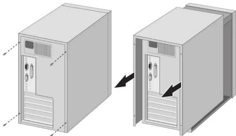
Remove the system cover and select any empty PCIe slot. See Figure 9 on page 31.
If you do not know how to identify a PCIe slot, refer to your system documentation.
natural_image
Diagram showing two views of a server rack cabinet with ventilation slots and ventilation ducts, no text or symbols present.Figure 9. Removing the PC Cover
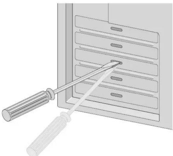
- Select an empty, non-shared PCIe slot and remove the faceplate.
Keep the faceplate in a safe place. You may need it for future use. See Figure 10.
natural_image
Illustration of a screwdriver inserted into a rack-mounted device (no text or symbols visible)Figure 10. Removing the Faceplate From PCIe Slot
Note
If you cannot locate or know how to find a PCIe slot, refer to the documentation that came with your system.
- Remove the network adapter from the shipping package and store the packaging material in a safe location.

Warning
The module is being installed in a system that operates with voltages that can be lethal. Before you remove the cover of your system, you must observe the following precautions to protect yourself and to prevent damage to the system components.
- Remove any metallic objects or jewelry from your hands and wrists.
- Make sure to use only insulated or nonconducting tools.
- Verify that the system is powered OFF and unplugged before accessing internal components.
-
Installation or removal of modules must be performed in a static-free environment. The use of a properly grounded wrist strap or other personal antistatic devices and an antistatic mat is strongly recommended. E39
-
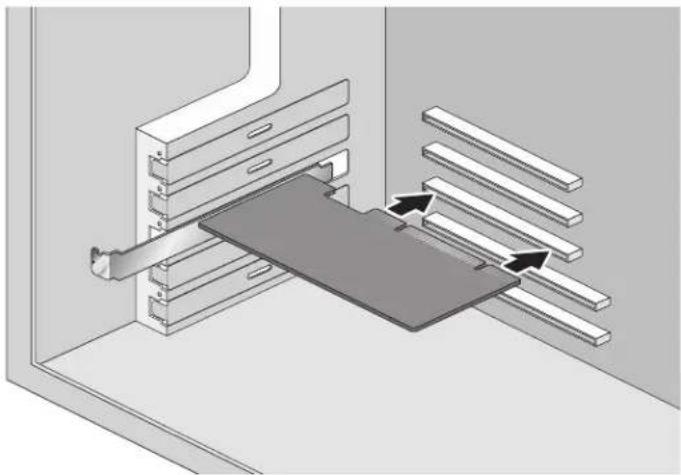
Applying even pressure at both corners of the network adapter, push the adapter until it is firmly seated in the PCIe slot.
Make sure the adapter is securely seated. See Figure 11 on page 32.
natural_image
3D diagram of a mechanical assembly with layered components and directional arrows indicating motion (no text or symbols)Figure 11. Inserting the Network Adapter

Caution
Do not use excessive force when seating the adapter, as the force may damage the system or the adapter. If the adapter resists seating, remove it from the system, realign it, and try again. E47
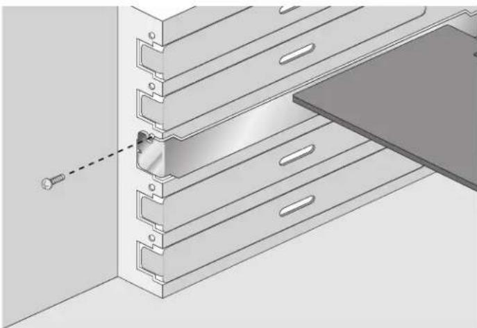
- Secure the network adapter to the chassis with a Phillips-head screw (not provided) as shown in Figure 12.
natural_image
3D technical illustration of a mechanical assembly with mounting holes and a dashed line indicating a connection point (no text or symbols present)Figure 12. Securing the Network Adapter
- Replace the system's cover and secure it with the screws removed in step 2.
- Disconnect any personal antistatic devices.
- Power the system on.
When the system returns to proper operation, the network adapter is fully installed. Next, connect the network cables. See “Connecting the Network Cables” on page 34.
Connecting the Network Cables
Connecting a Fiber Optic Network Cable
The 2914 series network adapter is equipped with the fiber optic port. To connect the network adapter to the network, you must have a fiber optic cable with the appropriate connector.
To connect a fiber optic network cable to the network adapter, perform the following procedure:
- Prepare a fiber optic cable with an appropriate connector.

Warning
The fiber optic ports contain a Class 1 laser device. When the ports are disconnected, always cover them with the provided plug. Exposed ports may cause skin or eye damage. L4
-
Remove a rubber plug from the network adapter.
-
Connect one end of the cable to the network adapter.
-
Connect the other end of the cable to the appropriate Ethernet network port or fiber optic port.
After the system is connected to the network and power is supplied, the network adapter attempts to negotiate duplex and flow control via the auto-negotiation protocol. If the link partner does not support Auto-negotiation, the network adapter bypasses the process and attempts to establish a link at 1000Mpbs in full duplex.
Note
After the cable is properly connected at both ends, the adapter card LED should be functional. See Table 1 on page 16 for a description of LED operation.
Connecting an SFP Transceiver
The AT-2914SP network adapter requires an SFP transceiver and an appropriate cable to connect to the network.
-
Insert an SFP transceiver into the SFP slot on the network adapter until the SFP transceiver snaps into place in the slot.
-
Remove a plug from the SFP transceiver.
-
Connect one end of the cable to the SFP transceiver.
-
Connect the other end of the cable to the appropriate Ethernet network port or an appropriate port.
After the system is connected to the network and power is supplied, the network adapter attempts to establish the connection as follow:
☐ With a Gigabit SFP, the network adapter attempts to negotiate duplex and flow control via the auto-negotiation protocol. If the link partner does not support Auto-negotiation, the network adapter bypasses the process and attempts to establish a link at 1000Mpbs in full duplex.
☐ With a 100Mbps SFP, the network adapter attempts to establish the connection at 100Mps in full-duplex.
Chapter 3
Installing the Driver Software
This chapter describes how to install driver software for the 2914 series network adapter onto your operating system. It contains the following topics:
☐ "Overview" on page 38
☐ "Downloading the Driver Software" on page 39
☐ “Accessing Device Manager” on page 41
☐ "Installing the Driver Software" on page 42
☐ “Updating the Driver Software” on page 45
☐ “Performing the Silent Installation” on page 46
Overview
When you install the 2914 series network adapter on your computer, your next step is to install driver software onto your Windows operating system. You can install driver software using Device Manager or using the silent installation method.
When you install driver software using Device Manager, the dialog boxes guide you through the installation process. On the other hand, using the silent installation method, you can install software without constant interactions by suppressing dialog boxes.
Guidelines
Here are the guidelines for installing and updating the driver software on your operating system:
☐ To install or update the driver software, you must have administrative privileges.
☐ When you install the 2914 series network adapter on your computer and start the system, the system detects a new adapter and may install a default driver. Or, the native Broadcom driver may be installed if your system has an onboard Broadcom network interface. In either case, you must update the driver software for the 2914 series network adapter. See “Installing the Driver Using Device Manager”, or “Installing the Driver Using the Silent Installation Method”.
Installing the Driver Using Device Manager
To install or update the driver software using Device Manager, follow the steps below:
☐ "Downloading the Driver Software" on page 39
☐ “Accessing Device Manager” on page 41
☐ "Installing the Driver Software" on page 42
Or
☐ "Updating the Driver Software" on page 45
Installing the Driver Using the Silent Installation Method
To install or update the driver software using the silent installation, follow the steps below:
☐ "Downloading the Driver Software" on page 39
☐ “Performing the Silent Installation” on page 46
Downloading the Driver Software
The 2914 series network adapter is not shipped with a software driver CD. You must download driver software from the Allied Telesis website.
To download driver software, do the following:
- Open a web browser, such as Internet Explorer or Firefox, on your system and enter the following:
http://www.alliedtelesis.com/support/software
The Allied Telesis Software Download page is displayed as shown in Figure 13.
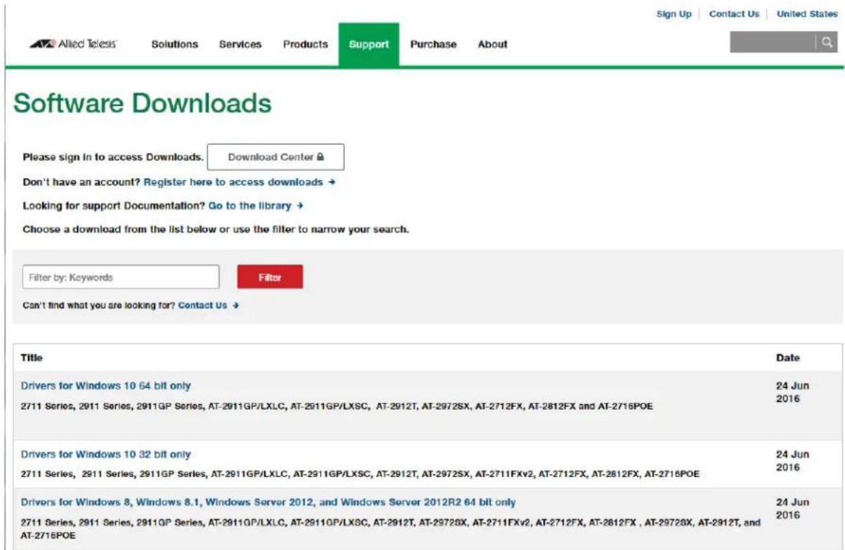
Figure 13. Software Downloads Search Result Example
- Select the driver for the 2914 series network adapter and your operating system.
- Save the zip folder onto your system.
- Right-click the zip folder and select Extract All.
A window as shown in Figure 14 pops up and prompts you to specify the location of a folder that you want to place unzipped files in.
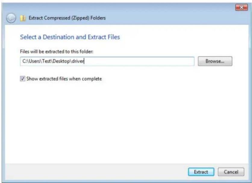
Figure 14. Specifying the Folder for Unzipped Files
- Specify the location of the folder and click Extract.
- Record the location of the folder.
Accessing Device Manager
When you install or update the driver software for 2914 series network adapter, you must first access Device Manager.
The procedures for accessing Device Manager are slightly different among Windows operating systems. To access Device Manager on your operating system, follow one of the procedures below:
Accessing Device Manager on Windows 8 and Windows 10
To access Device Manager on Windows 8 or Windows 10, do the following:
- Right-click the bottom left corner.
The Quick Access Menu appears. - Select Device Manager.
The Device Manager window appears as shown in Figure 15.
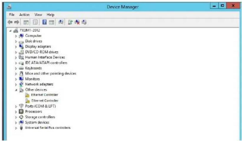
Figure 15. Device Manager on Windows 8
Accessing Device Manager on Windows 7
To access Device Manager on Windows 7, do the following:
- Left-click the start button at the bottom left corner.
The Windows menu appears.
- Type "device manager" in the search box.
The Device Manager window appears.
Installing the Driver Software
Once you physically install the 2914 series network card, the system detects the new hardware and creates an entry in Device Manager when the Windows operating system first boots up. Shortly after you log in, you need to install the driver software for your adapter card.
Note
To install the driver software, you must have administrative privileges.
To install the driver software, do the following:
- Access Device Manager. see "Accessing Device Manager" on page 41.
- In the Device Manager window, double-click Network Adapters to expand the field.
- Right-click Allied Telesis AT-2914 Series Fiber Ethernet.
Note
Device Manager my list your adapter entry as an Ethernet Controller, Broadcom NetXtreme device, or Allied Telesis device.
The shortcut menu appears. See Figure 16 as an example.
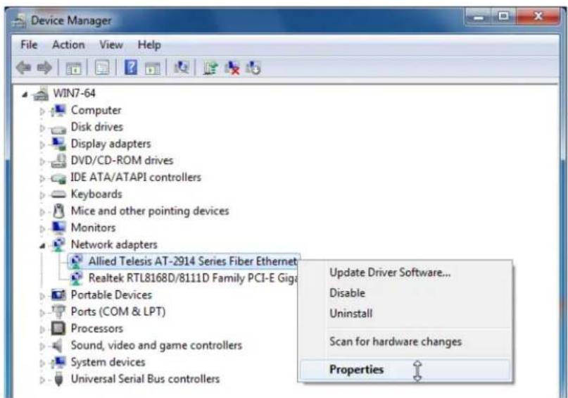
Figure 16. Selecting the 2914 Series Adapter in Device Manager
4. Select Update Driver Software.
The Update Driver Software window pops up. See Figure 17 on page 43 as an example.
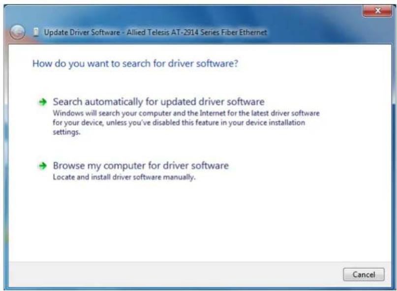
Figure 17. Update Driver Software Window
5. Select Browse my computer for driver software.
The Update Driver Software window prompts you to enter the location of the driver folder. See Figure 18 as an example.
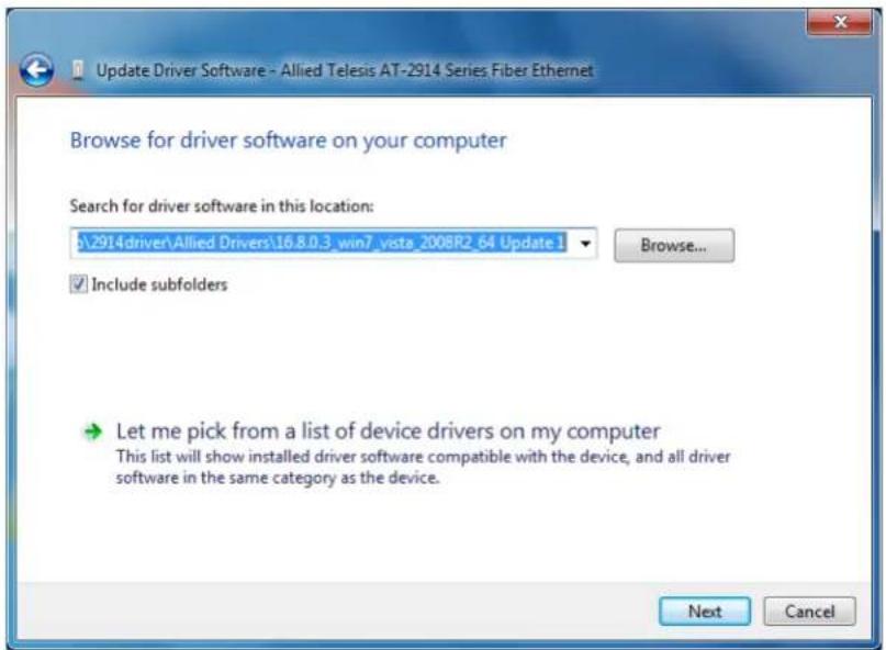
Figure 18. Update Driver Software Window
-
Specify the location of the driver software. See "Downloading the Driver Software" on page 39 for details.
-
Click Next.
The confirmation message shown in Figure 19 on page 44 appears when the driver software is successfully updated.
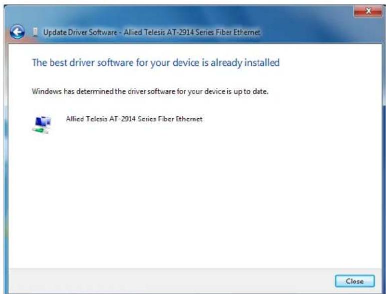
Figure 19. Update Driver Software Window Confirmation
- Click Close.
Updating the Driver Software
If your operating system automatically installs a default driver or Broadcom driver, you need to update the driver software with the driver that you downloaded from the Allied Telesis website. To obtain the latest version of the AT-2914 network adapter driver, see “Downloading the Driver Software” on page 39.
To update the driver software, you use the same procedure for installing the driver software for the first time. The only difference between updating and installing the driver software is the name of your adapter that Device Manager detects and lists.
Device Manager lists your adapter card entry as Allied Telesis AT-2914 Series Fiber Ethernet once you installed the driver software. Before you installed the driver software, Device Manager may list your adapter entry as an Ethernet Controller, Broadcom NetXtreme device, or Allied Telesis device.
To update the driver software for your AT-2914 network adapter, see "Installing the Driver Software" on page 42.
Performing the Silent Installation
To simplify the driver installation process, you may perform a silent installation when installing driver software for the AT-2914 network adapter card entries. The silent installation is a method of installing software in the silent mode without constant interactions by suppressing dialog boxes.
Note
You can apply the silent installation method only to Microsoft certified drivers. The drivers that Allied Telesis provides for the AT-2914 network adapters are all Microsoft certified.
Use a command line utility called Driver package Installer (DPInst) for the silent installation. DPInst is included in the Windows Developer Kit (WDK) provided by Microsoft. You can obtain the latest DPInst by downloading and installing the latest WDK from the Microsoft website.
Installing the Driver Silently
To install the driver silently, perform the following instructions:
- Create a folder in your Windows system.
- Download driver software for the AT-2914 network adapter.
See "Downloading the Driver Software" on page 39.
- Place the driver files that you downloaded into the folder that you created in step 1.
The folder should include the following driver files:
- Download the latest WDK to obtain the dpinst utility.
Consult Microsoft websites to download WDK.
- Place the dpinst.exe and its supporting files in the same folder where you placed the driver files.
You must place the 64-bit dpinst utility if your operating system is the 64-bit version. Place the 32-bit for dpinst utility for the 32-bit version operating system.
-
Open a command prompt window with administrator privileges.
-
Change the directory to the folder where the dpinst utility and the driver files reside.
- Install the driver in the silent mode by entering the following command:
dpinst /S
Note
Adding the /S switch to the dpinst command suppresses the display of wizard pages, user dialog boxes, and other user intervention requests.
The driver is installed silently.
Viewing Supported DPInst Options
You can display help information about the dpinst command-line options.
View all supported dpinst options by executing the following command:
- Open a command prompt window with administrator privileges.
- Change the directory to the folder where the dpinst utility and the driver files reside.
dpinst /?
The command displays the help text.
This chapter includes the following topics:
☐ “Overview” on page 50
☐ “Accessing Advanced Properties” on page 51
☐ “802.3az EEE” on page 52
☐ “ARP Offload” on page 53
☐ "Ethernet@WireSpeed" on page 54
☐ "Flow Control" on page 55
☐ “Interrupt Moderation” on page 57
☐ “Jumbo Mtu” on page 58
☐ “Large Send Offload v2 (IPv4)” on page 59
☐ "Large Send Offload v2 (IPv6)" on page 61
☐ "Maximum Number of RSS Queues" on page 62
☐ "Network Address" on page 64
☐ "NS Offload" on page 66
☐ "Priority & VLAN" on page 67
☐ "Receive Side Scaling" on page 69
☐ "Speed & Duplex" on page 70
☐ "TCP/UDP Checksum Offload (IPv4)" on page 72
☐ "TCP/UDP Checksum Offload (IPv6)" on page 74
☐ "VLAN ID" on page 76
☐ "Wake on Magic Packet" on page 77
☐ “Wake on Pattern Match” on page 78
☐ "WOL Speed" on page 79
Overview
The 2914 series network adapters allow you to modify advanced properties to meet your requirements. To access the advanced properties, access Device Manager, then go to each advanced property page.
Guidelines Here are the guidelines to modifying the advanced properties:
☐ To change the advanced property settings, you must have Administrator privileges.
☐ When you upgrade the driver software, the settings of the advanced properties may change. Verify the settings after upgrading the driver software.
Accessing Advanced Properties
To modify advanced properties, first access Device Manager, open the properties of your adapter, and select a feature you want to change its setting.
-
Access Device Manager. See "Accessing Device Manager" on page 41.
-
In the Device Manager window, double-click Allied Telesis AT-2914 Series Fiber Ethernet.
The properties window pops up.
- Click the Advanced tab.
The Advanced Properties window opens as shown in Figure 20.
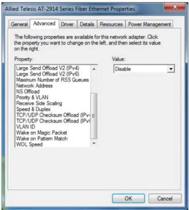
Figure 20. Advanced Properties Window
802.3az EEE
The 802.3az EEE (Energy Efficient Ethernet) property allows you to optimize the energy usage of the interface over Ethernet.
Note
This feature is valid only for copper ports. Because the port of the 2914 series network adapter is a fiber connector, the setting is always disabled.
To view the 802.3az EEE feature, do the following:
- Access the Advanced Properties.
See "Accessing Advanced Properties" on page 51.
- Select 802.3az EEE in the Property box.
The 802.3az EEE page is displayed as shown in Figure 21.
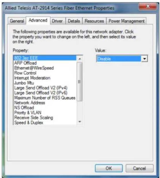
Figure 21. 802.3az EEE Page
- Click OK.
The ARP Offload feature enables the adapter not to wake up when responding to an ARP request. ARP is used to verify whether a computer is still present on the network and resolute an IP address into a MAC address.
To enable or disable the ARP Offload feature, do the following:
- Access the Advanced Properties.
See "Accessing Advanced Properties" on page 51.
- Select ARP Offload in the Property box.
The ARP Offload page is displayed as shown in Figure 22.
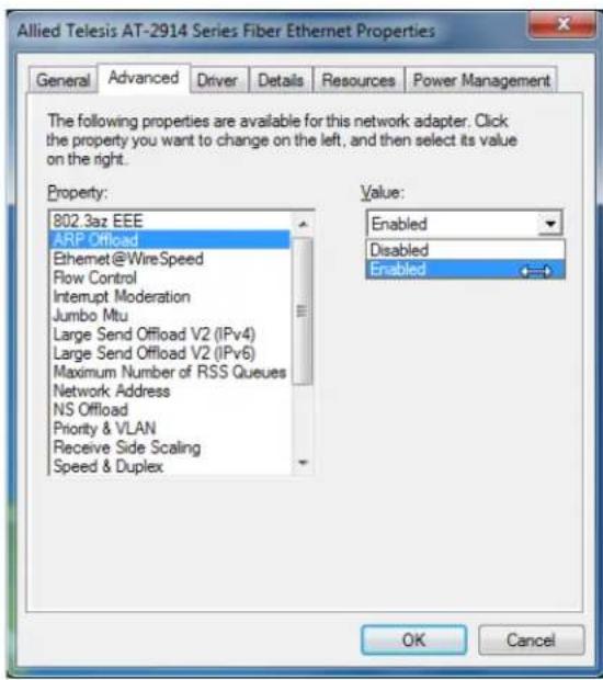
Figure 22. ARP Offload Page
- Select one of the following options:
□ Disable — This feature is disabled.
□ Enable — The adapter does not wake up when responding to an ARP request. This is the default setting.
- Click OK.
Ethernet@WireSpeed
The Ethernet@WireSpeed feature connects two devices even when the devices are connected through an impaired copper cable.
Note
This feature is valid only for copper ports. Because the port of the 2914 series network adapter is a fiber connector, the setting is always disabled.
To view the Ethernet@WireSpeed setting, do the following:
- Access the Advanced Properties.
See "Accessing Advanced Properties" on page 51.
- Select Ethernet@WireSpeed in the Property box.
The Ethernet@WireSpeed page is displayed as shown in Figure 23.
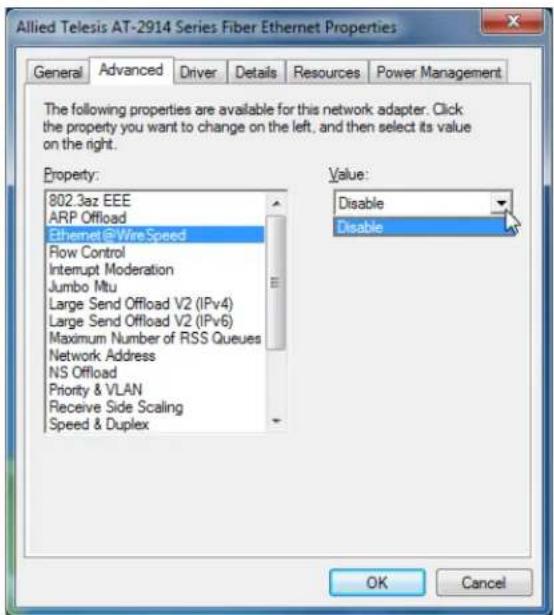
Figure 23. Ethernet@WireSpeed Page
- Click OK.
Flow Control
The Flow Control feature allows you to control the flow between the AT-2914 adapter port and its link partner. You can enable or disable the adapter port to process received PAUSE frames and transmit PAUSE frames.
To enable or disable the Flow Control feature, do the following:
- Access the Advanced Properties.
See "Accessing Advanced Properties" on page 51.
- Select Flow Control in the Property box.
The Flow Control page is displayed as shown in Figure 24.
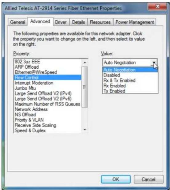
Figure 24. Flow Control Page
- Select one of the following options if available:
Note
The options and default setting depend on your operating system and the version of the driver that you installed.
☐ Auto Negotiation — The setting of the Flow Control property is determined during the auto-negotiation process.
□ Disabled — The adapter ignores PAUSE frames.
☐ Tx & Rx Enabled — The adapter processes PAUSE frames when receiving and transmits PAUSE frames.
☐ Rx Enabled — The adapter processes PAUSE frames when receiving, but does not transmit PAUSE frame.
☐ Tx Enabled — The adapter transmits PAUSE frames, but ignores PAUSE frames when receiving.
4. Click OK.
Interrupt Moderation
The Interrupt Moderation feature allows you to limit the rate of interrupts to the CPU during packet transmission and packet reception. When this feature is enabled, interrupts are handled as a group so that the CPU utilization decreases; however, the latency may increase.
To enable or disable the Interrupt Moderation feature, do the following:
- Access the Advanced Properties.
See "Accessing Advanced Properties" on page 51.
- Select Interrupt Moderation in the Property box.
The Interrupt Moderation page is displayed as shown in Figure 25.
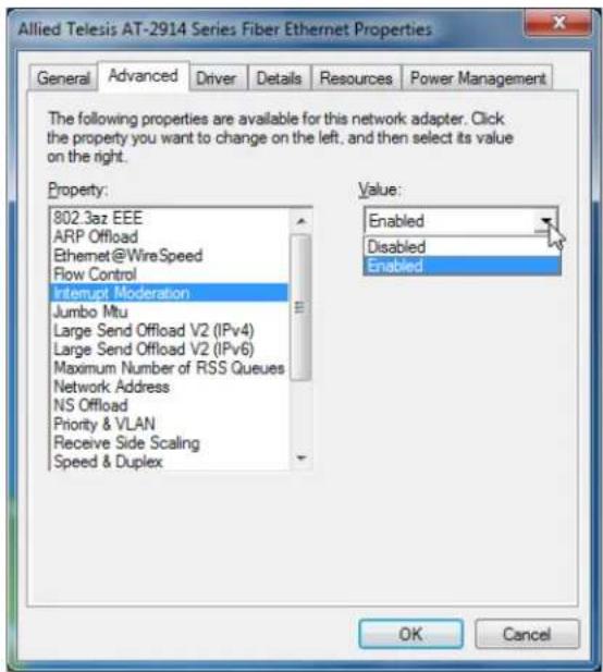
Figure 25. Interrupt Moderation Page
- Select one of the following options:
□ Disable — The Interrupt Moderation feature is disabled
□ Enable — The Interrupt Moderation feature is enabled. This is the default setting.
- Click OK.
Jumbo Mtu
The Jumbo Mtu (Maximum transmission unit) feature allows you to specify the size of the Ethernet frame that the adapter port supports. The network performance usually improves when the larger frame size is specified; however, the network must be capable of supporting the oversized Ethernet frames.
To change the Jumbo Mtu setting, do the following:
- Access the Advanced Properties.
See "Accessing Advanced Properties" on page 51.
- Select Jumbo Mtu in the Property box.
The Jumbo Mtu page is displayed as shown in Figure 26.
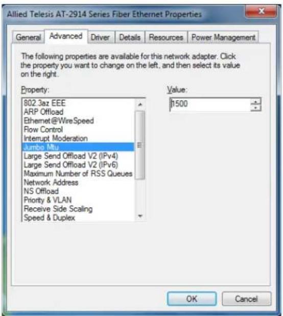
Figure 26. Jumbo Mtu Page
- Specify the size of the frame in the Value box.
The range of the value is from 1,500 to 9,000. The default value is 1,500.
- Click OK.
Large Send Offload v2 (IPv4)
The Large Send Offload v2 (IPv4) feature allows you to control the load of sending out large packets. When this feature is enabled, the adapter port segments large packets for IPv4 traffic and reduces the CPU load.
This feature, which supports large packets up to 256kb, overrides the Large Send Offload (IPv4) feature if both features are enabled.
To enable or disable the Large Send Offload v2 (IPv4) feature, do the following:
- Access the Advanced Properties.
See "Accessing Advanced Properties" on page 51.
- Select Large Send Offload v2 (IPv4) in the Property box.
The Large Send Offload v2 (IPv4) page is displayed as shown in Figure 27.
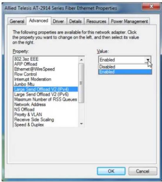
Figure 27. Large Send Offload v2 (IPv4) Page
- Select one of the following options:
□ Disable — The feature is disabled.
☐ Enable — The adapter port segments large packets up to 256kb for IPv4 traffic before sending them out. This is the default setting.
- Click OK.
Large Send Offload v2 (IPv6)
The Large Send Offload v2 (IPv6) feature allows you to control the load of sending out large packets. When this feature is enabled, the adapter port segments large packets for IPv6 traffic and reduces the CPU load.
To enable or disable the Large Send Offload v2 (IPv6) feature, do the following:
- Access the Advanced Properties.
See "Accessing Advanced Properties" on page 51.
- Select Large Send Offload v2 (IPv6) in the Property box.
The Large Send Offload v2 (IPv6) page is displayed as shown in Figure 28.
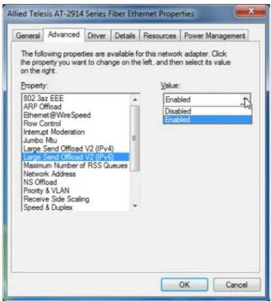
Figure 28. Large Send Offload (IPv6) Page
- Select one of the following options:
□ Disable — The adapter does not segment packets for IPv6 traffic.
☐ Enable — The adapter port segments large packets up to 256kb for IPv6 traffic before sending them out. This is the default setting.
- Click OK.
Maximum Number of RSS Queues
The RSS Queues feature allocates queue space between the network adapter and processor. You can specify the maximum number of RSS queues that the network adapter assigns receiving data to.
To specify or change the maximum number of RSS Queues, do the following:
- Access the Advanced Properties.
See "Accessing Advanced Properties" on page 51.
- Select Maximum Number of RSS Queues in the Property box.
The Maximum Number of RSS Queues page is displayed as shown in Figure 29.
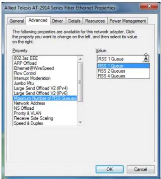
Figure 29. Maximum Number of RSS Queues Page
- Select one of the following options:
Note
The supported number of RSS queues and default setting depend on the network adapter and operation system. You might not see all options listed below.
☐ RSS 4 Queues — The system allocates up to four RSS queues.
☐ RSS 1 Queue — The system allocates up to one RSS queue.
☐ RSS 2 Queue — The system allocates up to two RSS queues. 4. Click OK.
Network Address
The Network Address property allows you to replace the MAC address originally assigned to the adapter with a user-defined address. The user-defined address that you assign to the adapter is called a locally administered address.

Caution
A locally administered address overrides the original MAC address stored in the hardware. When you change the MAC address, be sure to assign a unique MAC address. E81
To assign or change the Network Address, do the following:
- Access the Advanced Properties.
See "Accessing Advanced Properties" on page 51.
- Select Network Address in the Property box.
The Network Address page is displayed as shown in Figure 30.
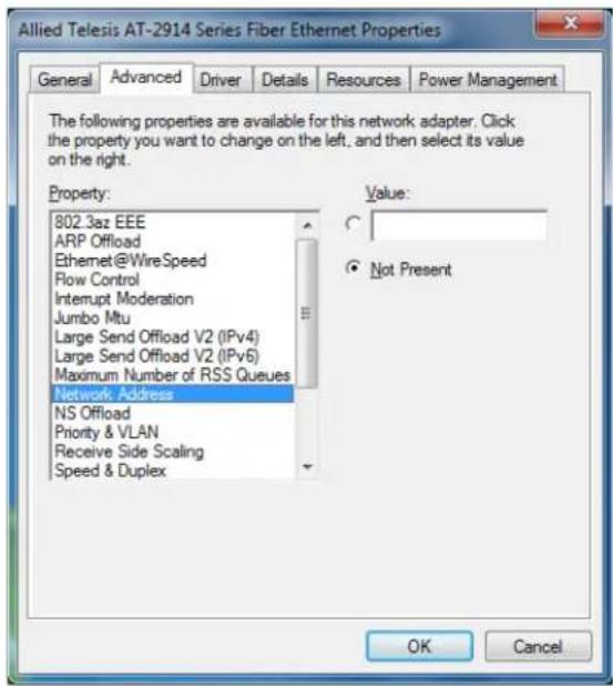
Figure 30. Network Address Page
- In the Value text box, enter a locally administered address for the AT-2914 network adapter.
By default, no locally administered address is assigned.
Here are guidelines to assigning a locally administered address:
☐ The address must be unique.
☐ The address consists of a 12-digit hexadecimal number, for example, "000C46005501."
☐ The range is from 0000 0000 0001 to FFFF FFFF FFFD excluding multicast MAC addresses, which cannot be used. The multicast MAC address has the least significant bit of the most significant octet as 1.
- Click OK.
NS Offload
The NS (Neighbor Solicitation) Offload feature enables the adapter not to wake up when responding to an NS request.
To enable or disable the NS Offload feature, do the following:
- Access the Advanced Properties.
See "Accessing Advanced Properties" on page 51.
- Select NS Offload in the Property box.
The NS Offload page is displayed as shown in Figure 31.
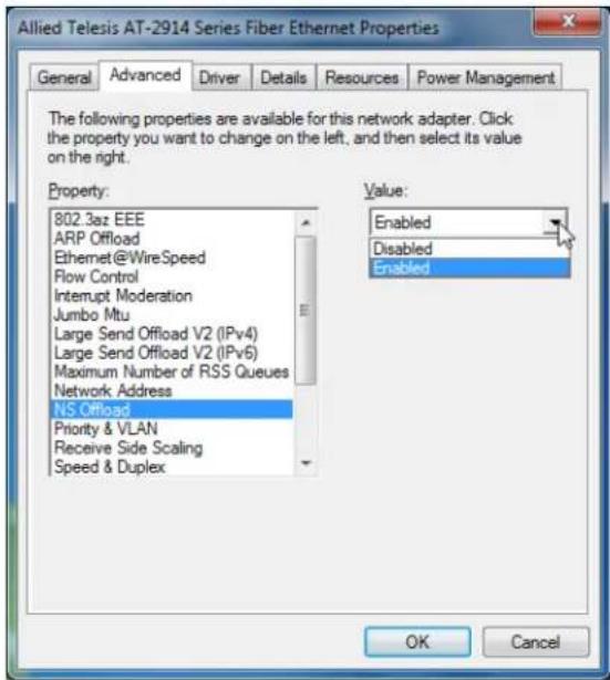
- Select one of the following options:
□ Disable — This feature is disabled.
☐ Enable — The adapter does not wake up when responding to an NS request. This is the default setting.
- Click OK.
The Priority & VLAN feature allows you to control sending and receiving tagged frames of QoS and VLAN.
When the property is set to Priority & VLAN Enabled, the adapter sends and receives QoS and VLAN tagged frames; with Priority Enabled, the adapter sends and receives QoS tagged frames; with VLAN Enabled, the adapter sends and receives VLAN tagged frames. To assign a VLAN ID to the adapter, see "VLAN ID" on page 76.
To enable or disable the Priority & VLAN feature, do the following:
- Access the Advanced Properties.
See "Accessing Advanced Properties" on page 51.
- Select Priority & VLAN in the Property box.
The Priority & VLAN page is displayed as shown in Figure 32.
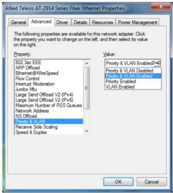
Figure 32. Priority & VLAN Page
- Select one of the following options:
☐ Priority & VLAN Enabled — The adapter sends and receives QoS and VLAN tagged frames. This is the default setting.
☐ Priority & VLAN Disabled — The adapter does not send and ignores QoS and VLAN tagged frames.
☐ Priority Enabled — The adapter sends and receives QoS tagged frames.
☐ VLAN Enabled — The adapter sends and receives VLAN tagged frames.
- Click OK.
Receive Side Scaling
The Receive Side Scaling (RSS) feature allows the adapter to efficiently distribute receive processing across multiple CPU's and to prevent from overloading a single CPU. To make this feature effective, the computer must have multiple CPU's in a multiprocessor system.
To enable or disable the Receive Side Scaling feature, do the following:
- Access the Advanced Properties.
See "Accessing Advanced Properties" on page 51.
- Select Receive Side Scaling in the Property box.
The Receive Side Scaling page is displayed as shown in Figure 33.
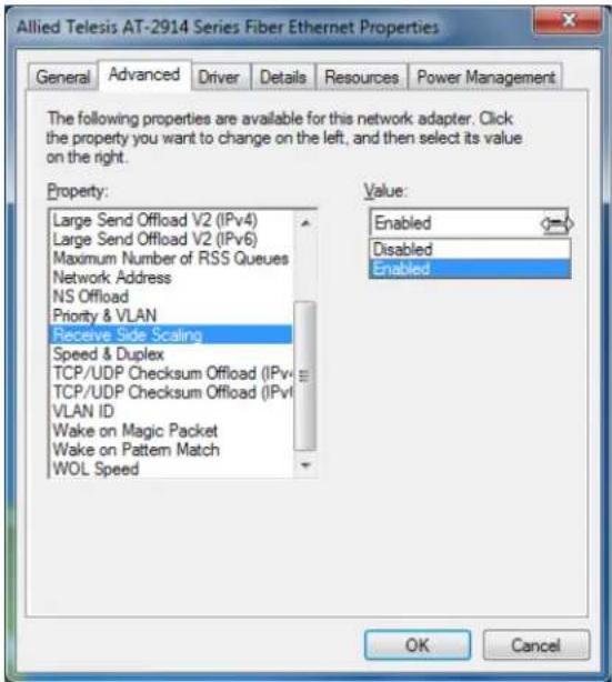
Figure 33. Receive Side Scaling Page
- Select one of the following options:
□ Enable — Receiving data is processed by multiple CPU's. This is the default setting.
□ Disable — Receiving data is processed by a single CPU.
- Click OK.
Speed & Duplex
The Speed & Duplex property sets the link speed and duplex mode for the copper port. For the fiber port, Auto Negotiation is specified.
Note
Because the port of the 2914 series network adapter is a fiber connector, the setting is always Auto-negotiation.
When the system is connected to the network and power is supplied, a network adapter attempts as follows:
☐ The AT-2914SX/SC and AT-2914SX/LC adapters attempt to negotiate duplex and flow control. If the link partner does not support Auto-negotiation, the network adapter bypasses the process and attempts to establish at 1000Mbps in full duplex.
☐ The AT-2914SP adapter with a Gigabit SFP transceiver attempts to negotiate duplex and flow control. If the link partner does not support Auto-negotiation, the network adapter bypasses the process and attempts to establish at 1000Mbps in full duplex.
☐ The AT-2914SP adapter with a 100Mbps SFP transceiver attempts to establish at 100Mbps in full duplex.
To view the Speed & Duplex property, do the following:
- Access the Advanced Properties.
See "Accessing Advanced Properties" on page 51.
- Select Speed & Duplex in the Property box.
The Speed & Duplex page is displayed as shown in Figure 34 on page 71.
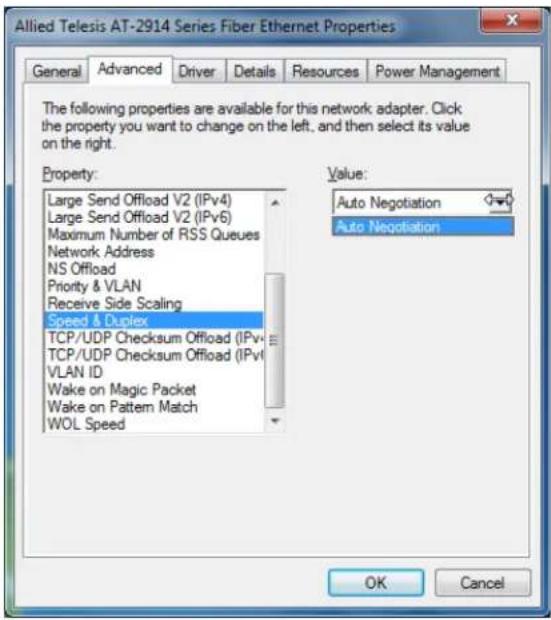
Figure 34. Speed & Duplex Page
- Click OK.
TCP/UDP Checksum Offload (IPv4)
The TCP/UDP Checksum Offload (IPv4) function enables the adapter port to compute the checksum of transmitting IPv4 packets and verify the checksum of receiving IPv4 packets, taking load off from the CPU.
To modify the TCP/UDP Checksum Offload (IPv4) setting, do the following:
- Access the Device Manager on your operating system.
See "Accessing Advanced Properties" on page 51.
- Select TCP/UDP Checksum Offload (IPv4) in the Property box.
The TCP/UDP Checksum Offload (IPv4) page is displayed as shown in Figure 35.
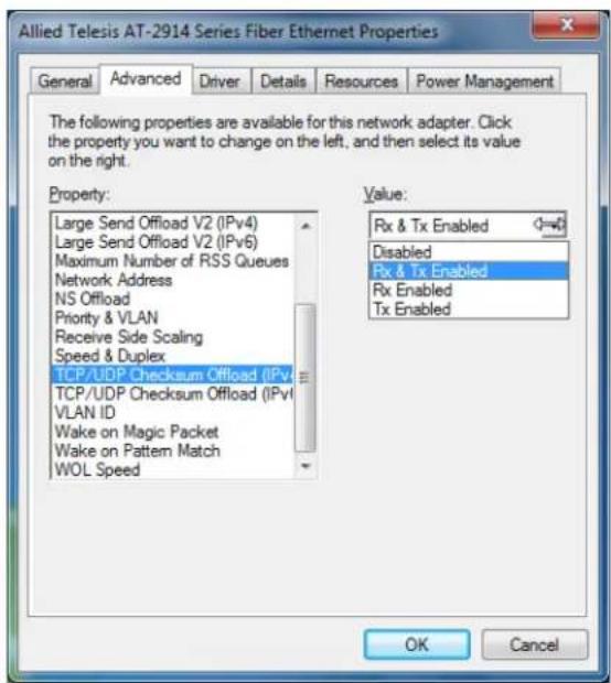
Figure 35. TCP/UDP Checksum Offload (IPv4) Page
- Select one of the following options:
☐ Rx & Tx Enabled — Enables the TCP/UDP Checksum Offload (IPv4) function for both receiving and transmitting IPv4 packets. This is the default setting.
☐ Disabled — Disables the TCP/UDP Checksum Offload (IPv4) function for both receiving and transmitting.
☐ Rx Enabled — Enables the TCP/UDP Checksum Offload (IPv4) function only for receiving IPv4 packets.
☐ Tx Enabled — Enables the TCP/UDP Checksum Offload (IPv4) function only for transmitting IPv4 packets.
- Click OK.
TCP/UDP Checksum Offload (IPv6)
The TCP/UDP Checksum Offload (IPv6) function enables the adapter port to compute the checksum of transmitting IPv6 packets and verify the checksum of receiving IPv6 packets, taking load off from the CPU.
To enable or disable the TCP/UDP Checksum Offload (IPv6) feature, do the following:
- Access the Device Manager on your operating system.
See "Accessing Advanced Properties" on page 51.
- Select TCP/UDP Checksum Offload (IPv6) in the Property box.
The TCP/UDP Checksum Offload (IPv6) page is displayed as shown in Figure 36.
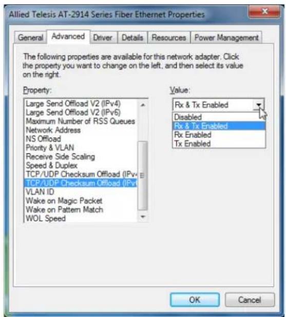
Figure 36. TCP/UDP Checksum Offload (IPv6) Page
- Select one of the following options:
☐ Rx & Tx Enabled — Enables the TCP/UDP Checksum Offload (IPv6) function for both receiving and transmitting IPv6 packets. This is the default setting.
□ Disabled — Disables the TCP/UDP Checksum Offload (IPv6) function for both receiving and transmitting.
☐ Rx Enabled — Enables the TCP/UDP Checksum Offload (IPv6) function only for receiving IPv6 packets.
☐ Tx Enabled — Enables the TCP/UDP Checksum Offload (IPv6) function only for transmitting IPv6 packets.
- Click OK.
VLAN ID
The VLAN ID property allows you to specify a VLAN ID on your network to the adapter port. The adapter port adds the value of the VLAN ID to a frame in the VLAN tag before transmitting the frame.
To change the VLAN ID value, do the following:
- Access the Advanced Properties.
See "Accessing Advanced Properties" on page 51.
- Select VLAN ID in the Property box.
The VLAN ID page is displayed as shown in Figure 37.
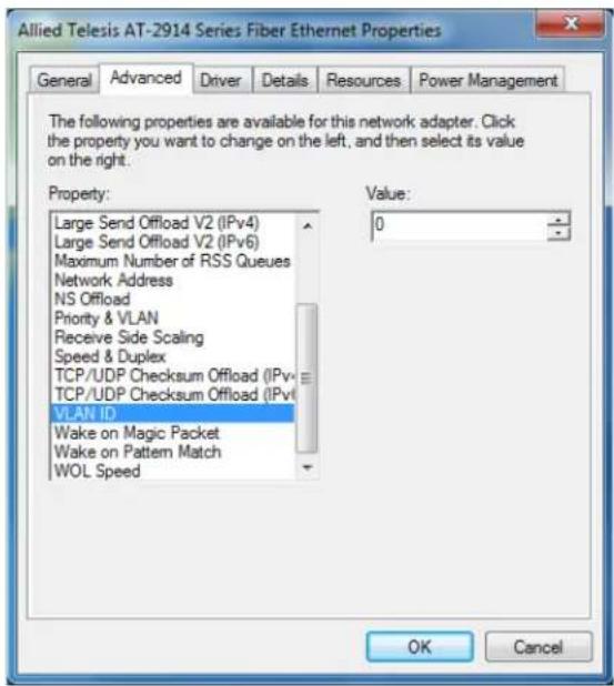
Figure 37. VLAN ID Page
- Specify a VLAN ID in the Value box.
The range of the value is from 0 to 4094. The default value is 0.
- Click OK.
Wake on Magic Packet
The Wake on Magic Packet feature enables the adapter to wake up from a low-power mode when the adapter port receives a Magic packet.
To enable or disable the Wake on Magic Packet feature, do the following:
- Access the Advanced Properties.
See "Accessing Advanced Properties" on page 51.
- Select Wake on Magic Packet in the Property box.
The Wake on Magic Packet page is displayed as shown in Figure 38.
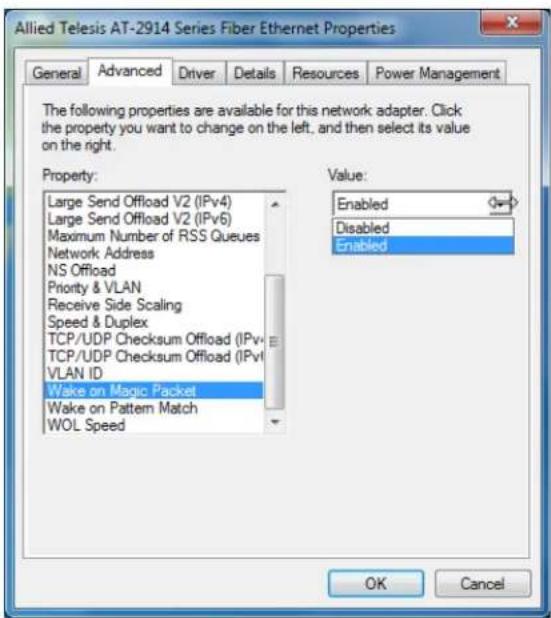
Figure 38. Wake on Magic Packet Page
- Select one of the following options:
□ Enable — The adapter wakes up from a low-power mode when receiving a Magic Packet. This is the default setting.
□ Disable — The adapter stays in a low-power mode when receiving a Magic Packet.
- Click OK.
Wake on Pattern Match
The Wake on Pattern Match feature enables the network adapter to wake up from a low-power mode when the packet matches the wake patterns specified in the operating system.
To enable of disable the Wake on Pattern Match feature, do the following:
- Access the Advanced Properties.
See "Accessing Advanced Properties" on page 51.
- Select Wake on Pattern Match in the Property box.
The Wake on Pattern Match page is displayed as shown in Figure 39.
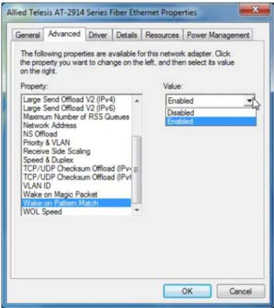
Figure 39. Wake on Pattern Match Page
- Select one of the following options:
□ Enable — The adapter wakes up from a low-power mode when receiving a packet that matches one of the patterns specified in the operating system.
□ Disable — The adapter stays in a low-power mode.
- Click OK.
The WOL Speed property allows you to specify the speed of Wake-on-LAN on your adapter port. This speed does not affect the speed of the fiber connection to your network.
To view this setting, do the following:
- Access the Advanced Properties.
See "Accessing Advanced Properties" on page 51.
- Select WOL Speed in the Property box.
The WOL Speed page is displayed as shown in Figure 40.
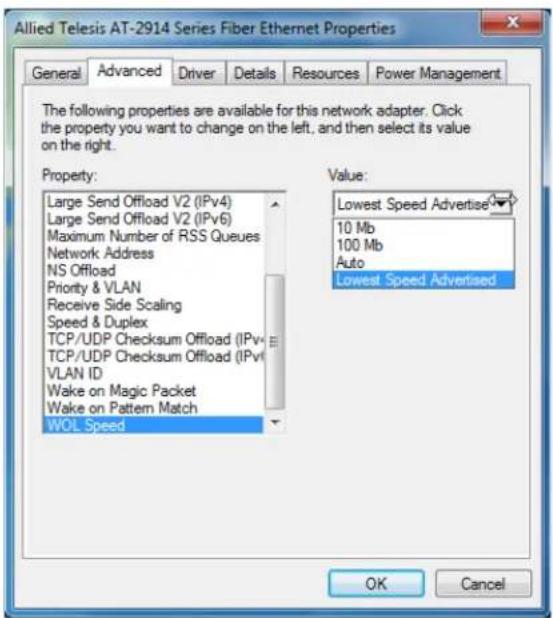
Figure 40. WOL Speed Page
- Select one of the following options:
☐ 10 Mb — The speed of Wake-on-LAN is 10 Mbps.
☐ 100 Mb — The speed of Wake-on-LAN is 10 Mbps.
□ Auto — The speed of Wake-on-LAN is auto negotiated.
☐ Lowest Speed Advertised — This is the default setting.
- Click OK.
Chapter 5
Uninstalling the Driver Software
This chapter describes how to uninstall the driver software for the 2914 series network adapter.
This chapter contains the following topics:
☐ "Overview" on page 82
☐ “Uninstalling the Driver Software Using Device Manager” on page 83
☐ “Uninstalling the Driver Software Silently” on page 84
Overview
When you no longer use the AT-2914 network adapter for your computer, you can uninstall the driver software from your operating system.
As you can install driver software for the AT-2914 network adapter using Device Manager or the silent installation method, you can also uninstall driver software in two ways:
☐ “Uninstalling the Driver Software Using Device Manager” on page 83
☐ “Uninstalling the Driver Software Silently” on page 84
Guidelines
Here are the guidelines for uninstalling the driver software from your system:
☐ You must have Administrator privileges to remove the driver software.
☐ Before uninstalling the network adapter, capture all of the Advanced Property settings for later use. The properties are lost during the uninstall process.
Uninstalling the Driver Software Using Device Manager
To uninstall the driver software from your operating system, do the following:
-
Start your Windows operating system and log in.
-
Access the Device Manager.
See "Accessing Device Manager" on page 41.
-
In the Device Manager window, expand the Network Adapters folder.
-
Right-click the Allied Telesis AT-2914 Series Fiber Ethernet.
The shortcut menu appears as shown in Figure 41.
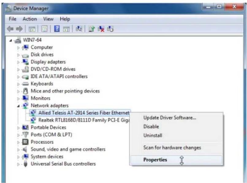
Figure 41. Device Manager Shortcut Menu
- Select Uninstall.
The Confirm Device Uninstall window pops up.
-
Check the check box if you want to remove the driver software for your adapter.
-
Click OK to complete the uninstalling.
Uninstalling the Driver Software Silently
You can apply the silent installation method to uninstall the driver.
To uninstall the driver without user-intervention, perform the following steps:
- Open a command prompt window with administrator privileges.
- Change the directory to the folder where the dpinst utility and the driver files reside.
- Uninstall the driver silently by executing the following command:
> dpinst /u inf_file_name.inf /s
Note
Replace inf_file_name with the name of .inf file.
The driver is uninstalled without user-intervention.
Chapter 6
Troubleshooting
This chapter describes troubleshooting procedures. It contains the following sections:
☐ “Checking the Port LED on the Adapter” on page 86
☐ "Troubleshooting Checklist" on page 87
☐ "Testing Network Connectivity" on page 88
Checking the Port LED on the Adapter
The 2914 series network adapter comes with one LED. The LED indicates the link status for the c port.
Note
Before the port LED can provide troubleshooting information, the driver software for your particular operating system must be installed and the adapter must be connected to the network. See Chapter 3, "Installing the Driver Software" on page 37.
Table 3 describes the link status that LED's indicate.
Table 3. LED Status
| State Description | |
| On Valid link. | |
| Off No link. | |
| Flashing The | port is receiving or transmitting network packets |
Troubleshooting Checklist
The following checklist provides recommended actions to take to resolve problems installing the AT-2914 adapter card or running it in your system.
Note
Before opening the cabinet of your system for removing or inserting the adapter card, review all precautions outlined under “Reviewing Safety Precautions” on page 25.
☐ Inspect all cables and connections. Verify that the cable connections between the adapter and the switch are attached properly. Make sure that the cable length and rating are compliant with the requirements listed in "Connecting the Network Cables" on page 34."
☐ Verify that you match the wavelength of the network adapter port with the wavelength of the switch port. The AT-2914SX/SC or AT-2914SX/LC network adapter should be connected to a 1000BASE-SX switch port. For the AT-2914SP network adapter, the wavelength of the SFP installed to the network adapter must be matched with the wavelength of the switch port.
☐ Check the adapter installation by reviewing Chapter 2, “Installing the Hardware” on page 23.
☐ Make sure that the adapter card is properly seated in a PCIe slot. Check for specific hardware problems, such as obvious damage to board components or the PCIe edge connector.
☐ Check the configuration settings and change them if they are in conflict with another device.
☐ Make sure that your system is using the latest BIOS.
☐ Try inserting the adapter card in another slot. If the new position works, the original slot in your system may be defective.
☐ Replace the failed adapter card with one that is known to work properly. If the second adapter card works in the slot where the first one failed, the original adapter card is probably defective.
☐ Install the adapter card in another functioning system and run the tests again. If the adapter card passed the tests in the new system, the original system may be defective.
☐ Remove all other adapter cards from the system and run the tests again. If the adapter card passes the tests, the other adapter cards may be causing contention.
Testing Network Connectivity
This section describes how to test network connectivity for Windows and Linux networks.
Note
When you are using the fiber optic port, both the adapter and the switch must be set to the same speed and duplex mode.
Windows To test the network connectivity for the Windows driver software, perform the following procedure.
Use the ping command to determine if network connectivity is working.
- Click the icon at the left bottom corner of the Windows.
- In the search box, type cmd and click OK.
- Type ipconfig /all
The command window opens, as shown in Figure 42.
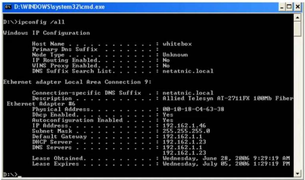
Figure 42. Command Window with ipconfig/all displayed
- Type ping
from the command line, then press Enter.
The network connectivity information is displayed, as shown in Figure 43.
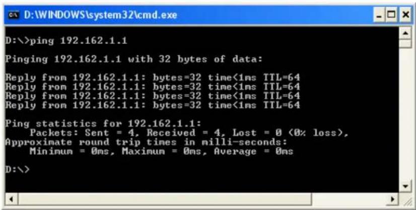
Figure 43. Command Window with ping displayed
Linux To verify that the Ethernet interface is up and running, run 'ifconfig' to check the status of the Ethernet interface. In addition, you can use the 'netstat -i' command to check the statistics on the Ethernet interface. Consult the manual pages for more information about the 'ifconfig' and 'netstat' commands.
To ping an IP host on the network to verify connection has been established, perform the following procedure.
-
From the command line, type ping
. -
Press Enter.
The command displays the packet send/receive status.
Physical Specifications
Dimensions: 87.6mm x 68.9mm (3.5in. x 2.7in.)
(without a bracket)
Weight: 40g (1.4 oz)
(without a bracket)
Environmental Specifications
Operating Temperature: 0°C to 50°C (32°F to 122°F)
Storage Temperature: -25°C to 80°C (-°13F to 176°F)
Relative Humidity: 5% to 90% (non-condensing)
Altitude: 3,048 m (10,000 ft.)
Power Specifications
Signaling Voltage: 3.3 V
Power Consumption: 2.0 Watts
Optical Specifications
SX Output Optical Power: -9.5 (Min) -4 (Max) dBM
Optical Sensitivity: -19 (Typ) -17 (Max) dBM
Center Wavelength 850 nm
LX Output Optical Power: -9 (Min) -3 (Max) dBM
Optical Sensitivity: -20 (Typ) -19 (Max) dBM
Center Wavelength 1310 nm
This appendix contains the following regulatory statements:
☐ "Federal Communication Commission Interference Statement" on page 94
☐ "Industry Canada Statement" on page 96
☐ “Europe - EU Declaration of Conformity” on page 99
Federal Communication Commission Interference Statement
This device complies with Part 15 of the FCC Rules. Operation is subject to the following two conditions: (1) This device may not cause harmful interference, and (2) this device must accept any interference received, including interference that may cause undesired operation.
This equipment has been tested and found to comply with the limits for a Class B digital device, pursuant to Part 15 of the FCC Rules. These limits are designed to provide reasonable protection against harmful interference in a residential installation. This equipment generates, uses and can radiate radio frequency energy and, if not installed and used in accordance with the instructions, may cause harmful interference to radio communications. However, there is no guarantee that interference will not occur in a particular installation. If this equipment does cause harmful interference to radio or television reception, which can be determined by turning the equipment off and on, the user is encouraged to try to correct the interference by one of the following measures:
☐ Reorient or relocate the receiving antenna.
☐ Increase the separation between the equipment and receiver.
☐ Connect the equipment into an outlet on a circuit different from that to which the receiver is connected.
□ Consult the dealer or an experienced radio/TV technician for help.

Caution
FCC Caution: Any changes or modifications not expressly approved by the party responsible for compliance could void the user's authority to operate this equipment. E80

Caution
This transmitter must not be co-located or operating in conjunction with any other antenna or transmitter.
The transmission in the band from 5600MHz to 5650MHz is disabled by the software installed on the device. You cannot change this setting. This device meets all the other requirements specified in the Part 15E, Section 15.407 of the FCC Rules.
Radiation Exposure Statement
This equipment complies with FCC radiation exposure limits set forth for an uncontrolled environment. This equipment should be installed and operated with minimum distance 32cm between the radiator & your body.
Country Code Selection (WiFi Devices)
Note
The non-US model of this product has a country code setting that must be set during the initial management session of the unit. The setting ensures that the unit operates in compliance with the laws and regulations of your country or region.
For the US model, the country code is preset and cannot be changed. Per FCC regulations, the country code setting for all WiFi products marketed in the US must be fixed to US operational channels only.
Industry Canada Statement
This device complies with RSS-247 of the Industry Canada Rules. Operation is subject to the following two conditions: (1) This device may not cause harmful interference, and (2) this device must accept any interference received, including interference that may cause undesired operation.
(i) the device for operation in the band 5150-5250 MHz is only for indoor use to reduce the potential for harmful interference to co-channel mobile satellite systems;
(ii) the maximum antenna gain permitted for devices in the bands 5250-5350 MHz and 5470-5725 MHz shall comply with the e.i.r.p. limit; and
(iii) the maximum antenna gain permitted for devices in the band 5725-5825 MHz shall comply with the e.i.r.p. limits specified for point-to-point and non point-to-point operation as appropriate.
(iv) Users should also be advised that high-power radars are allocated as primary users (i.e. priority users) of the bands 5250-5350 MHz and 5650-5850 MHz and that these radars could cause interference and/or damage to LE-LAN devices.
Avertissement:
Radiation Exposure Statement:
This equipment complies with IC radiation exposure limits set forth for an uncontrolled environment. This equipment should be installed and operated with minimum distance 32cm between the radiator & your body.
Professional Installation Instruction:
1. Installation personal
This product is designed for specific application and needs to be installed by a qualified personal who has RF and related rule knowledge. The general user shall not attempt to install or change the setting.
2. Installation location
The product shall be installed at a location where the radiating antenna can be kept 32cm from nearby person in normal operation condition to meet regulatory RF exposure requirement.
3. External antenna
Use only the antennas which have been approved by the applicant. The non-approved antenna(s) may produce unwanted spurious or excessive RF transmitting power which may lead to the violation of FCC/IC limit and is prohibited.
4. Installation procedure
Please refer to user's manual for the detail.
5. Warning
Please carefully select the installation position and make sure that the final output power does not exceed the limit set force in relevant rules. The violation of the rule could lead to serious federal penalty.
Europe - EU Declaration of Conformity
This device complies with the essential requirements of the R&TTE Directive 1999/5/EC. The following test methods have been applied in order to prove presumption of conformity with the essential requirements of the R&TTE Directive 1999/5/EC:
Europe – EU Declaration of Conformity
This device complies with the essential requirements of the R&TTE Directive 1999/5/EC. The following test methods have been applied in order to prove presumption of conformity with the essential requirements of the R&TTE Directive 1999/5/EC:
□ EN 60950-1
Safety of Information Technology Equipment
□ EN 50385
Product standard to demonstrate the compliance of radio base stations and fixed terminal stations for wireless telecommunication systems with the basic restrictions or the reference levels related to human exposure to radio frequency electromagnetic fields (110MHz - 40 GHz) - General public
EN 300 328
Electromagnetic compatibility and Radio spectrum Matters (ERM); Wideband transmission systems; Data transmission equipment operating in the 2.4GHz ISM band and using wide band modulation techniques; Harmonized EN covering the essential requirements of article 3.2 of the R&TTE Directive
□ EN 301 893
Broadband Radio Access Networks (BRAN); 5GHz high performance RLAN; Harmonized EN covering the essential requirements of article 3.2 of the R&TTE Directive
EN 301 489-1
Electromagnetic compatibility and Radio spectrum Matters (ERM); ElectroMagnetic Compatibility (EMC) standard for radio equipment and services; Part 1: Common technical requirements
□ EN 301 489-17
Electromagnetic compatibility and Radio spectrum Matters (ERM); ElectroMagnetic Compatibility (EMC) standard for radio equipment; Part 17: Specific conditions for Broadband Data Transmission Systems
CE0560①
Table 4. Declaration of Conformity
| Country Declaration Statement | |
| Česky [Czech] | Allied Telesis tímto prohlašuje, že tento wireless access point je ve shodě se základními požadavky a dalšími příslušnými ustanoveními směrnice 1999/5/ES. |
| Dansk [Danish] | Undertegnede Allied Telesis erklærer herved, at følgende udstyr wireless access point overholder de væsentlige krav og øvrige relevante krav i direktiv 1999/5/EF. |
| Deutsch [German] | Hiermit erklärt Allied Telesis, dass sich das Gerät wireless access point in Übereinstimmung mit den grundlegenden Anforderungen und den übrigen einschlägigen Bestimmungen der Richtlinie 1999/5/EG befindet. |
| Eesti [Estonian] | Käesolevaga kinnitab Allied Telesis seadme wireless access point vastavust direktiivi 1999/5/EÜ põhinõuetele ja nimetatud direktiivist tulenevatele teistele asjakohastele sätetele. |
| English Hereby | Allied Telesis, declares that this wireless access point is in compliance with the essential requirements and other relevant provisions of Directive 1999/5/EC. |
| Español [Spanish] | Por medio de la presente Allied Telesis declara que el wireless access point cumple con los requisitos esenciales y cualesquiera otras disposiciones aplicables o exigibles de la Directiva 1999/5/CE. |
| Ελληνική [Greek] | ME THN ΠΑΡΟΥΣΑ Allied Telesis ΔΗΛΩΝΕΙ OTI wireless access point ΣΥΜΜΟΡΦΩΝΕΤΑΙ ΠΡΟΣ ΤΙΣ ΟΥΣΙΩΔΕΙΣ ΑΠΑΙΤΗΣΕΙΣ ΚΑΙ ΤΙΣ ΛΟΙΠΕΣ ΣΧΕΤΙΚΕΣ ΔΙΑΤΑΞΕΙΣ ΤΗΣ ΟΔΗΓΙΑΣ 1999/5/ΕΚ. |
| Français [French] | Par la présente Allied Telesis déclare que l'appareil wireless access point est conforme aux exigences essentielles et aux autres dispositions pertinentes de la directive 1999/5/CE. |
| Italiano [Italian] | Con la presente Allied Telesis dichiara che questo wireless access point è conforme ai requisiti essenziali ed alle altre disposizioni pertinenti stabilite dalla direttiva 1999/5/CE. |
| Latviski [Latvian] | Ar šo Allied Telesis deklarē, ka wireless access point atbilst Direktīvas 1999/5/EK būtiskajām prasībām un citiem ar to saistītajiem noteikumiem. |
| Lietuvių [Lithuanian] | Šiuo Allied Telesis deklaruoja, kad šis wireless access point atitinka esminius reikalavimus ir kitas 1999/5/EB Direktyvos nuostatas. |
| Nederlands [Dutch] | Hierbij verklaart Allied Telesis dat het toestel wireless access point in overeenstemming is met de essentiële eisen en de andere relevante bepalingen van richtlijn 1999/5/EG. |
| Malti [Maltese] | Hawnhekk, Allied Telesis, jiddikjara li dan wireless access point jikkonforma mal-ħtiġijiet essenzjali u ma provvedimenti oħrajn relevanti li hemm fid-Dirrettiva 1999/5/EC. |
| Magyar [Hungarian] | Alulírott, Allied Telesis nyilatkozom, hogy a wireless access point megfelel a vonatkozó alapvető követelményeknek és az 1999/5/EC irányelv egyéb előírásainak. |
| Polski [Polish] | Niniejszym Allied Telesis oświadcza, że wireless access point jest zgodny z zasadniczymi wymogami oraz pozostałymi stosownymi postanowieniami Dyrektywy 1999/5/EC. |
| Português [Portuguese ] | Allied Telesis declara que este wireless access point está conforme com os requisitos essenciais e outras disposições da Directiva 1999/5/CE. |
| Slovensko [Slovenian] | Allied Telesis izjavlja, da je ta wireless access point v skladu z bistvenimi zahtevami in ostalimi relevantnimi določili direktive 1999/5/ES. |
| Slovensky [Slovak] | Allied Telesis týmto vyhlasuje, že wireless access point spĺňa základné požiadavky a všetky príslušné ustanovenia Smernice 1999/5/ES. |
| Suomi [Finnish] | Allied Telesis vakuuttaa täten että wireless access point tyyppinen laite on direktiivin 1999/5/EY oleellisten vaatimusten ja sitä koskevien direktiivin muiden ehtojen mukainen. |
| Svenska [Swedish] | Härmed intygar Allied Telesis att denna wireless access point står I överensstämmelse med de väsentliga egenskapskrav och övriga relevanta bestämmelser som framgår av direktiv 1999/5/EG. |
This appendix provides how to clean fiber optic connectors and consists of the following sections:
☐ “Overview” on page 104
☐ “Cleaning Using a Cartridge-Type Cleaner” on page 105
☐ “Cleaning Using a Swab” on page 107
Overview
The fiber optic connector consists of a fiber optic plug and its adapter. The end of the fiber optic cable is held in the core of the ferrule in the plug as shown in Figure 44. Light signals are transmitted through the core of the fiber.
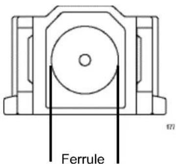
Figure 44. Ferrule in an SC Connector Plug
Even minor smudges or dirt on the end face of the fiber, completely invisible to the naked eye, can disrupt light transmission and lead to failure of the component or of the entire system. Figure 45 shows part of the end face of an unclean and clean ferrule.
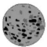
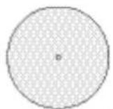
Unclean Clean
Figure 45. Unclean and Clean Ferrule
Guidelines Here are general guidelines and warnings for fiber optic connectors:
□ Always keep a dust cap on a fiber optic cable when it is not in use.
☐ Do not touch the end face of the ferrule in the connector.

Warning
Do not stare into the laser beam. ∞ L2

Warning
Do not look directly at the cable ends or inspect the cable ends with an optical lens. ∞ L6
Cleaning Using a Cartridge-Type Cleaner
Fiber optic cartridge cleaners are available from many vendors and are typically called “cartridge cleaners,” as shown in Figure 46.
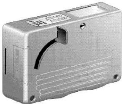
natural_image
Exterior view of a silver rectangular electronic device casing (no visible text or symbols)Figure 46. Cartridge Cleaner
Note
Do not use compressed air or aerosol air to clean a fiber optic connector.
To clean a fiber optic connector using a cartridge cleaner, perform the following procedure:
- With one hand, hold the cartridge cleaner and push the lever on the cleaning cartridge in the direction of the arrow to expose the cleaning surface, as shown in Figure 47.
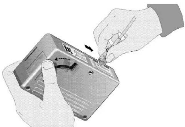
natural_image
Illustration of hands installing or adjusting a component with a tool, no visible text or symbolsFigure 47. Rubbing the Ferrule Tip on the Cleaning Surface
- Place the ferrule tip on the exposed cleaning surface and rub the ferrule in a downward direction, as shown in Figure 47.
Note
Rub the ferrule tip on the cleaning surface in one direction only.
- When you reach the end of the cleaning surface, pick up the ferrule tip, rotate and place it at the top and rub downwards at least 2 times.

Caution
Failing to pick up the ferrule tip when you reach the bottom of the cleaning surface can result in static electricity that can damage the fiber optic cable. E82
- If desired, repeat steps 2 and 3.
- If a fiber inspection scope is available, use the scope to inspect the ferrule end face to make sure that it is clean.
- Reconnect the cable to the port or protect the ferrule tip with a dust cap.
Cleaning Using a Swab
Specially treated swabs (stick cleaners) are available for cleaning inside connector adapters or hard-to-reach ferrule tips. These swabs, often referred to as "lint free" or "alcohol free" swabs, are available from many vendors. See Figure 48. Stick cleaners are available in both 2.5 mm and 1.25 mm sizes for use on SC and MU connectors respectively.
Note
NEVER use a household cotton swab and/or alcohol to clean a fiber optic connector. A cotton swab or alcohol may leave a residue on the ferrule tip.
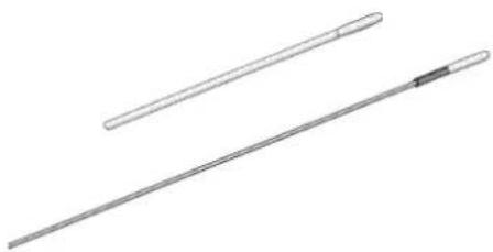
natural_image
Two elongated metal rods with different lengths, one extending into a narrow neck (no text or symbols visible)Figure 48. Lint-Free and Alcohol-Free Swabs
Note
Do not use compressed air or aerosol air to clean a fiber optic connector.
To clean a recessed ferrule using a swab, perform the following procedure:
- Insert the swab into the adapter as shown in Figure 49 and rub the ferrule tip with the swab.
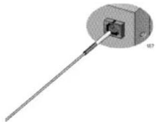
natural_image
3D diagram of a mechanical component with a rod and circular housing, no visible text or symbolsFigure 49. Cleaning a Recessed Ferrule
-
If desired, repeat step 1.
-
If a fiber inspection scope is available, use the scope to inspect the connector to make sure that it is clean.
- Reconnect the cable to the port or protect the ferrule tip with a dust cap.
- Installation and User's Guide
- Electrical Safety and Emissions Standards
- Declaration of Conformity
- Caution
- Avertissement
- Radiation Exposure Statement:
- European Union Restriction of the Use of Certain Hazardous Substances (RoHS) in Electrical and Electronic Equipment
- Note
- Safety and Electromagnetic Emissions Certificates
- Standard Compliance
- Certificates
- Electromagnetic Compatibility (EMC)
- Radio Equipment
- Safety
- Translated Safety Statements
- Contents
- Preface 9
- Chapter 1: Introduction ...... 13
- Chapter 2: Installing the Hardware ....23
- Chapter 3: Installing the Driver Software ....37
- Chapter 4: Modifying Advanced Properties ....49
- Safety Symbols Used in this Document
- Warning
- Description
- Series Network Adapter Models
- SC Optical Fiber Connector
- LC Fiber Optic Adapter
- Model Naming Conventions
- Supported Operating Systems
- Accessing Documents
- Allied Telesis Documents
- Contents of Your Shipment
- Warranty Registration
- Chapter 2
- Installing the Hardware
- System Requirements
- Reviewing Safety Precautions
- Pre-Installation Checklist
- Replacing the Bracket
- Installing a Network Adapter
- Connecting the Network Cables
- Connecting a Fiber Optic Network Cable
- Connecting an SFP Transceiver
- Chapter 3
- Installing the Driver Software
- Overview
- Guidelines
- Installing the Driver Using Device Manager
- Installing the Driver Using the Silent Installation Method
- Downloading the Driver Software
- http://www.alliedtelesis.com/support/software
- Accessing Device Manager
- Accessing Device Manager on Windows 8 and Windows 10
- Accessing Device Manager on Windows 7
- Select Update Driver Software.
- Select Browse my computer for driver software.
- Updating the Driver Software
- Performing the Silent Installation
- Installing the Driver Silently
- Viewing Supported DPInst Options
- This chapter includes the following topics:
- Accessing Advanced Properties
- 802.3az EEE
- Ethernet@WireSpeed
- Flow Control
- Click OK.
- Interrupt Moderation
- Jumbo Mtu
- Large Send Offload v2 (IPv4)
- Large Send Offload v2 (IPv6)
- Maximum Number of RSS Queues
- Network Address
- NS Offload
- Receive Side Scaling
- Speed & Duplex
- TCP/UDP Checksum Offload (IPv4)
- TCP/UDP Checksum Offload (IPv6)
- VLAN ID
- Wake on Magic Packet
- Wake on Pattern Match
- Chapter 5
- Uninstalling the Driver Software
- Uninstalling the Driver Software Using Device Manager
- Uninstalling the Driver Software Silently
- Chapter 6
- Troubleshooting
- Checking the Port LED on the Adapter
- Troubleshooting Checklist
- Testing Network Connectivity
- Physical Specifications
- Environmental Specifications
- Power Specifications
- Optical Specifications
- Federal Communication Commission Interference Statement
- Radiation Exposure Statement
- Country Code Selection (WiFi Devices)
- Industry Canada Statement
- Avertissement:
- Professional Installation Instruction:
- Installation personal
- Installation location
- External antenna
- Installation procedure
- Warning
- Europe - EU Declaration of Conformity
- Europe – EU Declaration of Conformity
- CE0560①
- Cleaning Using a Cartridge-Type Cleaner
- Cleaning Using a Swab
Brand : Allied Telesis
Model : 2914SP
Category : Network Card/Adapter