
DCM340 - Multimeter Megger - Free user manual and instructions
Find the device manual for free DCM340 Megger in PDF.


| Product Type | Digital Clamp Multimeter |
| Brand | Megger |
| Model | DCM340 |
| Dimensions | 230 x 70 x 38 mm |
| Weight | 300 g (with batteries) |
| Power Supply | 2 x AA batteries (1.5V) |
| Display | LCD, 4000 counts |
| AC Current Range | 0.1 A to 400 A |
| DC Current Range | 0.1 A to 400 A |
| AC/DC Voltage Range | 0.1 V to 600 V |
| Resistance Range | 0.1 Ω to 40 MΩ |
| Capacitance Range | 1 nF to 100 µF |
| Frequency Range | 10 Hz to 10 kHz |
| Temperature Measurement | -20 °C to 1000 °C (with type-K thermocouple) |
| Continuity Test | Yes, audible below 30 Ω |
| Diode Test | Yes |
| Data Hold | Yes |
| Auto Range | Yes |
| Safety Rating | CAT III 600 V |
| Operating Temperature | 0 °C to 40 °C |
| Storage Temperature | -10 °C to 50 °C |
| Relative Humidity | Up to 80% (non-condensing) |
| Accessories Included | Test leads, type-K thermocouple, batteries, pouch |
| Maintenance | Clean with a dry cloth; do not use solvents |
| Spare Parts / Repairability | Batteries and test leads are user-replaceable; other repairs by qualified personnel |
Frequently Asked Questions - DCM340 Megger
User questions about DCM340 Megger
0 question about this device. Answer the ones you know or ask your own.
Ask a new question about this device
Download the instructions for your Multimeter in PDF format for free! Find your manual DCM340 - Megger and take your electronic device back in hand. On this page are published all the documents necessary for the use of your device. DCM340 by Megger.
USER MANUAL DCM340 Megger
To ensure safe operation and service of the Meter, follow these instructions.
Failure to observe warnings can result in severe injury or death.
- Avoid working alone so assistance can be rendered.
■ To enhance safety, test leads should be disconnected from instrument when not in use.
■ Do not use test leads or the Clamp Meter if they look damaged.
■ Do not use the Meter if the Clamp Meter is not operating properly or if it is wet.
■ Use the Clamp Meter only as specified in the Instruction card or the protection provided by the Clamp Meter might be impaired.
■ Special precautions are necessary when operating in situations where exposed live parts at dangerous voltages may be encountered. Personal protective equipment (not supplied with this instrument) should be used.
The test leads should be disconnected from the instrument when making a current measurement.
■ Use caution with voltages above 30 V ac rms, or 60 V dc. These voltages pose a shock hazard.
■ To avoid false readings that could lead to electric shock and injury, replace the battery as soon as the low battery indicator (☐) appears.
CAUTION :
CAUTION : If the meter is used in the vicinity of equipment which generates electromagnetic interference, the display may become unstable or the measurements show may be subject to large errors.
1.1 Maintenance
Do not attempt to repair this Clamp Meter.
It contains no user-serviceable parts. Repair or serving should only be performed by qualified personal.
1.2 Cleaning
Periodically wipe the case with a dry cloth and detergent do not use abrasives or solvents.
1.3 Safety, Hazard and Warning symbols on the instrument
This paragraph details the various safety and hazard icons on the instrument's outer case.
| Icon Description | |
 | Warning: High Voltage, risk of electric shock |
 | Caution: Refer to user guide. |
 | UK conformity. This equipment complies with current UK legislation |
 | EU conformity. Equipment complies with current EU directives. |
 | Equipment complies with current 'C tick' requirements. |
 | Do not dispose of in the normal waste stream. |
| [HX26] | Equipment protected throughout by double insulation. |
 | AC measurement |
 | DC measurement |
| [WWX] | Reference earth connection. Not a protective earth terminal |
 | Battery |
CAT IV - Measurement category IV: Equipment connected between the origin of the low-voltage mains supply and distribution panel.
CAT III -Measurement category III: Equipment connected between the distribution panel and electrical outlets.
CAT II - Measurement category II: Equipment connected between the electrical outlets and user's equipment.
CAT I - Measurement category I: The circuits are not connected to mains.
Measurement equipment may be safely connected to circuits at the marked rating or lower. The connection rating is that of the lowest rated component in the measurement circuit.
2. Operation
2.1 Power On / Off
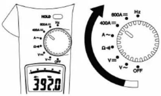
2.2 Auto Power Off

Auto Power Off disable : Press buttons (except Hold button) than switch the rotary knob to power on the Meter.
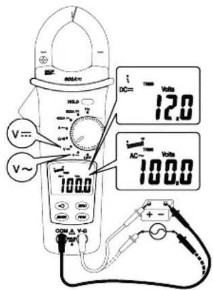
2.3 AC V / DC V
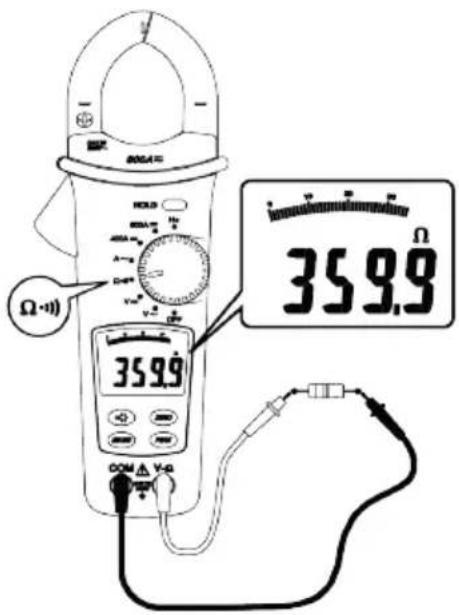
2.4 Resistance
2.5 Continuity

CAT.III.600 V with respect to earth for the jaw.
Do not hold the meter in front of the Tactile Barrier.
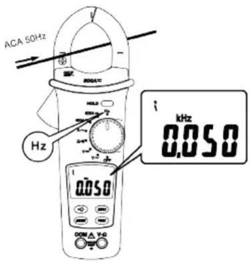
2.7 Hz
2.8 Zero
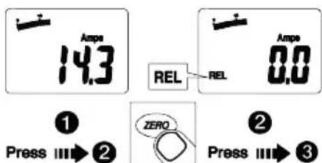
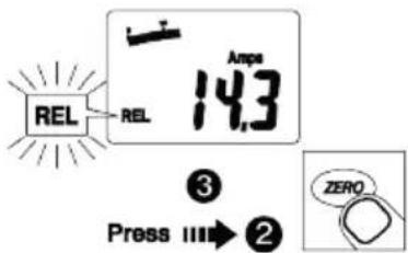
2: REL: Meter save the displayed offset value after one press of the ZERO button. The LCD is displaying the relative value.
3: REL (flashing): A second press of the ZERO button saves the offset value, with the present value then displayed.
1: Normal : Press and hold ZERO for ≥ 2 sec to return to normal operation and cancel the offset value.
2.9 Data Hold
2.10 Min / Max Hold
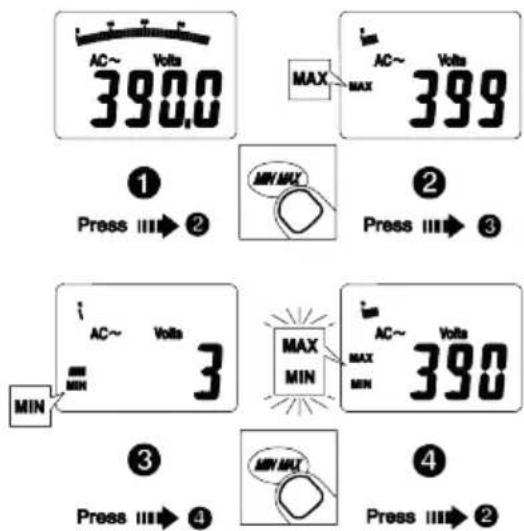
2: MAX: Meter is saving the maximum and minimum value. Maximum value is displayed
3: MIN: Meter is saving the maxi mum and minimum value. Minimum value is displayed
4: MAX MIN (flashing): Meter is saving the maximum and minimum values. Present value is displayed.
1: Normal : Press and hold MIN MAX to return to normal operation.
2.11 Battery Replacement

Low battery: " is displayed or flashes when a button pressed.
To avoid false readings that could lead to electric shock and injury, replace the battery as soon as the low battery indicator (appears.
2.12 Peak Hold

2: PMAX: Meter is saving the peak maximum and minimum value. Peak maximum value is displayed.
3: PMIN: Meter is saving the peak maximum and minimum value. Peak minimum value is displayed
4: CAL : Press and hold PEAK button ≥3 sec to calibrate the Meter itself for accurate measurement.
1: Normal : Press and hold PEAK button to return to normal operation.
2.13 Back Light

Back light Automatic off after 60 seconds.
3. Specifications
| Specification Detail | |
| 1-1 General Specifications | |
| LCD display digits : 3 3/4 digit large scale LCD readout. | |
| Display count : 4000 counts. | |
| Measuring rate : 1.5 times / sec. | |
| Overrange display : "OL" is displayed for "Ω" functions, shows the real value for "A" and "V" function. | |
| Automatic power off time : Approximately 30 minutes after | |
| Low battery indicator : |  is displayed. Replace the battery when the indicator [Yax2]appears in the display.To avoid false readings that could lead to electric shock and injury, replace the battery as soon as the low battery indicator appears. is displayed. Replace the battery when the indicator [Yax2]appears in the display.To avoid false readings that could lead to electric shock and injury, replace the battery as soon as the low battery indicator appears. |
| Power requirement : 9 V PP3 / 6LR61 battery. | Rechargeable batteries are not suitable for use with this instrument. |
| 1-2 Environmental Conditions | |
| Indoor Use. | |
| Calibration : One year calibration cycle. | |
| Operating temperature : 0 °C ~ 30 °C (±80% RH) | 30 °C ~ 40 °C (±75% RH) |
| 40 °C ~ 50 °C (±45% RH) | |
| Storage temperature : -20 to +60 °C, 0 to 80% RH (batteries not fitted). | |
| Overvoltage category : IEC 61010-1 600 V CAT.III. CAT.III equipment is designed to protect against the transients in the equipment in fixed installations, such as distribution panels, feeders and short branch circuits and lighting systems in large buildings. | |
| Operating altitude : 2000 m (6562 ft) | |
| Conductor Size : | 35 mm diameter. |
| Pollution degree : | 2 |
| EMC : | EN 61326-1 |
| Shock vibration : | Sinusoidal vibration per MIL-T- 28800E(5 ~ 55 Hz, 3 g maximum). |
| Drop Protection : | 1.2 m drop to hardwood on concrete floor. |
1-2 Environmental Conditions
| Indoor Use. | |
| Calibration : One year calibration cycle. | |
| Operating temperature : 0 °C ~ 30 °C (±80% RH) | 30 °C ~ 40 °C (±75% RH) |
| 40 °C ~ 50 °C (±45% RH) | |
| Storage temperature : -20 to +60 °C, 0 to 80% RH (batteries not fitted). | |
| Overvoltage category : IEC 61010-1 600 V | CAT.III. CAT.III equipment is designed to protect against the transients in the equipment in fixed installations, such as distribution panels, feeders and short branch circuits and lighting systems in large buildings. |
| Operating altitude : 2000 m (6562 ft) | |
| Conductor Size : | 35 mm diameter. |
| Pollution degree : | 2 |
| EMC : | EN 61326-1 |
| Shock vibration : | Sinusoidal vibration per MIL-T- 28800E(5 ~ 55 Hz, 3 g maximum). |
| Drop Protection : | 1.2 m drop to hardwood on concrete floor. |
1-3 Electrical Specifications
Accuracy is ±(% reading + number of digits) at 23 °C ±5 °C < 80%RH.
Temperature coefficient: Add 0.2 x (Specified accuracy) / °C, < 18 °C, > 28 °C.
Voltage
| Function | Range Accuracy | |
| V~ | 0~400.0 Vrms400~600 Vrms | ±(1.0%+5 dgt) 50Hz ~ 500 Hz |
| V= | 0~400.0 V400~600 V | ±(0.7% + 2 dgt) |
Over voltage protection : 600 V rms
Input Impedance : 1 MΩ // less than 100 pF.
AC Conversion Type : AC Conversion are average sensing rms indication calibrated to the rms value of a sine wave input.
Resistance and Continuity :
| Function Range | Accuracy | |
| Ω | 400.0 Ω | ±(1% + 3 dgt) |
Over voltage protection : 600 V rms
Max. open circuit voltage : 3 V
Continuity check : Internal sounds activates if the resistance of the circuit under test is less than 30Ω approximately.
AC Current
| Function | Range | Accuracy |
| A~(50~60 Hz) | 0~400.0 A ±(1 | .5%+ 5 dgt) *1 |
| 400~600 A | ±(2.0%+ 7 dgt) | |
| A~(61~400 Hz) | 0~400.0 A ±(2.0%+ 5 dgt) *1 | |
| 400~600 A | ±(2.5%+ 7 dgt) | |
*1 : Over 80% of full scale add ±1.6%
Overload protection :
600 A rms
AC Conversion Type and additional accuracy is same as AC Voltage.
Position Error : ±1% of reading.
DC Current
| Function | Range | Accuracy |
| A- | 0~400.0 A ±(1 | .2%+ 5 dgt) |
| 400~600 A ±(1.9%+ 7 dgt) | ||
Overload protection : 600 A rms
Position Error :
±1% of reading.
Specifications
| Addition error according to remanence : | 1% max. of current crest. | ||
| Auto Power Off (APO) The meter will automatically shut itself off after approximately 30 minutes after power on. | |||
| Frequency : Hz | Function | Range | Accuracy |
| 20~400 Hz | 1 Hz | ±(0.1% + 2 dgt) | |
| Overload protection : 600 A rms. | |||
| Sensitivity : | 3 A rms for ACA (A~) (>400 Hz Unspecified) | ||
| Peak Hold : ±(3% + 15dgt) *>600 Vpeak | Unspecified. *>600 A peak Unspecified. | ||
| Min/Max Hold : add ± 15 dgt to accuracy | for ACA / DCA.* Automatically switch to the low resolution range at Peak Hold and MIN MAX Hold. | ||
4. Limited Warranty
This Meter is warranted to the original purchaser against defects in material and workmanship for 1 year from the date of purchase. During this warranty period, manufacturer will, at its option, replace or repair the defective unit, subject to verification of the defect or malfunction.
This warranty does not cover, disposable batteries, or damage from abuse, neglect, accident, unauthorized repair, alteration, contamination, or abnormal conditions of operation or handling.
Any implied warranties arising out of the sale of this product, including but not limited to implied warranties of merchantability and fitness for a particular purpose, are limited to the above. The manufacturer shall not be liable for loss of use of the instrument or other incidental or consequential damages, expenses, or economic loss, or for any claim or claims for such damage, expense or economic loss. Some states or countries laws vary, so the above limitations or exclusions may not apply to you.
4.1 Decommissioning
4.2 WEEE Directive
The crossed out wheeled bin symbol placed on Megger products is a reminder not to dispose of the product at the end of its life with general waste.
Megger is registered in the UK as a Producer of Electrical and Electronic Equipment. The Registration No is WEE/HE0146QT.
For further information about disposal of the product consult your local Megger company or distributor or visit your local Megger website.
4.3 Battery disposal
The crossed out wheeled bin symbol placed on a battery is a reminder not to dispose of batteries with general waste when they reach the end of their usable life.
For disposal of batteries in other parts of the EU contact your local Megger branch or distributor.
Megger is registered in the UK as a producer of batteries (registration No.: BPRN00142).
For further information see www.megger.com
Manufacturing sites
| Megger Limited | Megger GmbH | Megger USA - Valley Forge |
| Archcliffe Road | Weststraße 59 | Valley Forge Corporate Center |
| Dover | 52074 Aachen | 2621 Van Buren Avenue |
| Kent | T. +49 (0) 241 91380 500 | Norristown |
| CT17 9EN | E. info@megger.de | Pennsylvania, 19403 |
| ENGLAND | USA | |
| T. +44 (0)1 304 502101 | T. +1 610 676 8500 | |
| F. +44 (0)1 304 207342 | F. +1 610 676 8610 |
| Megger USA - Dallas | Megger AB | Suite 100 |
| 4545 West Davis Street | Rinkebyvägen 19, Box 724, SE-182 17 | Fort Collins CO 80525 |
| Dallas TX 75237 | USA | |
| USA | DANDERYD | T. +1 970 282 1200 |
| T. 800 723 2861 (USA only) | T. +46 08 510 195 00 | |
| T. +1 214 333 3201 | E. seinfo@megger.com |
| E. USsales@megger.com | Megger USA - Fort Collins4812 McMurry Avenue |
The company reserves the right to change the specification or design without prior notice.
Megger is a registered trademark
DCM340_UG_en_V02 08 2021
© Megger Limited 2020 www.megger.com

- CAUTION :
- Maintenance
- Cleaning
- Safety, Hazard and Warning symbols on the instrument
- Operation
- Power On / Off
- Auto Power Off
- AC V / DC V
- Resistance
- Continuity
- Hz
- Zero
- Data Hold
- Min / Max Hold
- Battery Replacement
- Peak Hold
- Back Light
- Specifications
- 1-3 Electrical Specifications
- Specifications
- Limited Warranty
- Decommissioning
- WEEE Directive
- Battery disposal
Brand : Megger
Model : DCM340
Category : Multimeter