AVO830 - Multimeter Megger - Free user manual and instructions
Find the device manual for free AVO830 Megger in PDF.


| Product Type | Digital Multimeter |
| Brand | Megger |
| Model | AVO830 |
| Display Counts | 6000 |
| True RMS | Yes |
| AC Voltage Range | 0.1 mV to 1000 V |
| DC Voltage Range | 0.1 mV to 1000 V |
| AC Current Range | 0.1 μA to 10 A |
| DC Current Range | 0.1 μA to 10 A |
| Resistance Range | 0.1 Ω to 60 MΩ |
| Capacitance Range | 1 nF to 10 mF |
| Frequency Range | 10 Hz to 1 MHz |
| Temperature Range | -50°C to 1000°C |
| Safety Rating | CAT III 1000V, CAT IV 600V |
| Auto Range | Yes |
| Data Hold | Yes |
| Backlight | Yes |
| Continuity Test | Yes |
| Diode Test | Yes |
| Min/Max/Avg | Yes |
| Power Supply | 9V battery (NEDA 1604) |
| Dimensions | 190 x 90 x 50 mm |
| Weight | 400 g |
| Accessories Included | Test leads, thermocouple, battery, manual |
Frequently Asked Questions - AVO830 Megger
User questions about AVO830 Megger
0 question about this device. Answer the ones you know or ask your own.
Ask a new question about this device
Download the instructions for your Multimeter in PDF format for free! Find your manual AVO830 - Megger and take your electronic device back in hand. On this page are published all the documents necessary for the use of your device. AVO830 by Megger.
USER MANUAL AVO830 Megger
This document is copyright of:
Megger Limited, Archcliffe Road, Dover, Kent CT17 9EN. ENGLAND
T +44 (0)1304 502101 F +44 (0)1304 207342 www.megger.com
Megger Limited reserves the right to alter the specification of its products from time to time without notice. Although every effort is made to ensure the accuracy of the information contained within this document it is not warranted or represented by Megger Limited to be a complete and up-to-date description.
For Patent information about this instrument refer to the following web site:
megger.com/patents
This manual supersedes all previous issues of this manual. Please ensure that you are using the most recent issue of this document. Destroy any copies that are of an older issue.
Declaration of Conformity
Hereby, Megger Instruments Limited declares that radio equipment manufactured by Megger Instruments Limited described in this user guide is in compliance with Directive 2014/53/EU. Other equipment manufactured by Megger Instruments Limited described in this user guide is in compliance with Directives 2014/30/EU and 2014/35/EU where they apply.
The full text of Megger Instruments EU declarations of conformity are available at the following internet address:
megger.com/eu-dofc
1. Overview......6
1.1. Contact Megger UK....6
2. Safety 7
2.1. Safety Information ....7
2.2. Measurement Connection ....8
2.2.1. Voltage 8
2.2.2. CAT IV 8
2.2.3. CAT III 8
2.2.4. CAT II 8
2.3. Warnings, Cautions and Notes 8
2.3.1. Warnings 8
2.3.2. Cautions 8
2.3.3. Notes 8
2.4. Safety and Hazard Symbols....9
3. Introduction....10
3.4.1. Measurement Functions....10
4. Product Features....11
4.1. Overview....11
4.2. Function Buttons 12
4.3. Function Dial....13
4.4. Terminals....14
4.5. Display....15
5. Start-up Overview....16
5.1. Start-up and Shut-down.... 16
5.2. Auto Power Off (APO)....16
5.3. Battery Status 16
5.4. Range Selection....16
5.5. Backlight 16
6. Measurements....17
6.1. Non Contact Detection....17
6.2. Voltage Measurement....18
6.2.1. AC+DC Description....19
6.3. Phase Rotation / Sequence Detection 19
6.4. Resistance Measurement....20
6.4.1. Resistance Measurement Tips....21
6.5. Continuity Test....22
6.6. Conductance Measurement....23
6.7. Capacitance Measurement....24
6.7.1. Smart Capacitance 25
6.8. Diode Test 26
6.9. Frequency Measurement....28
6.10. Temperature Measurement 29
6.11. AC Voltage Detection....30
6.12. Current Measurement....31
6.12.1. Ampere Measurement....31
6.12.2. Milliampere Measurement....33
7. Maintenance....35
7.1. Batteries 35
7.1.1. Battery Status....35
7.2. Battery Replacement 35
7.3. Fuse Replacement....36
7.4. Clean the instrument 37
7.5. Technical Support 37
8. End of Life Disposal....38
8.1. WEEE Directive 38
8.2. Battery Disposal....38
9. Accessories....39
9.1. Optional and Replacement Accessories 39
10. Specifications....40
10.1. General Specifications....40
10.2. Technical Specifications....41
11. Repair and Warranty....43
11.1. Calibration, Service and Spare Parts....43
Figures
- Fig 1: Voltage Measurement Set-up....18
- Fig 2: Phase Rotation / Sequence Detection Set-up....19
- Fig 3: Resistance Measurement Set-up 20
- Fig 4: Continuity Test Set-up....22
- Fig 5: Conductance Measurement Set-up....23
- Fig 6: Capacitance Measurement Set-up....24
- Fig 7: Diode Test Set-up....26
- Fig 8: Forward Voltage Drop Across Semi-conductor Junction 27
- Fig 9: Frequency Measurement Set-up....28
- Fig 10: Temperature Measurement Set-up....29
- Fig 11: AC voltage Detection Set-up 30
- Fig 12: ≤ 10 A Measurement Set-up....31
- Fig 13: ≤ 100 mA Measurement Set-up....33
- Fig 14: Battery Replacement....35
- Fig 15: Fuse Replacement....36
1. Overview
Thank you for purchasing an AVO ^® digital multi-meter from Megger ^® . This User Guide details the specifications, functional aspects and how to use the Megger digital multi-meter model No. AVO8 Series.
For your own safety and to get the maximum benefit from this Megger instrument, read and understand the safety warnings and instructions before the instrument is used.
Megger reserves the right to improve the content of this User Guide from time to time without notice.
Megger reserves and retains the intellectual property rights of the content including the design, text, graphics, and logos in this User Guide. Any partial or complete reproduction or usage of the content is strictly prohibited.
For the latest version of this User Guide visit: www.megger.com
To register this instrument go to: uk.megger.com/register
1.0.1 Contact Megger UK
Megger Ltd.
Archcliffe Road
Dover
CT17 9EN
UK
Tel: +44 (0) 1304 502101
Email: uksales@megger.com
Web: www.megger.com
2. Safety
2.1 Safety Information
Retain these safety warnings for future reference.
Read and understand the safety information before using the instrument.
The following warnings must be obeyed.
Important: This instrument must be used only by suitably trained and competent persons.
Users of this instrument and their employers must do a valid risk assessment of all electrical work to identify potential sources of electrical danger and risk of electrical injury, and must conform to national safety legislation. Where assessment shows significant risk from high energy systems, the use of fused leads must be considered.
If the instrument is used in a manner not specified by the manufacturer, the protection provided by the instrument may be impaired.
The instrument must not be used if any part of it is damaged.
■ Use only Megger approved test leads and accessories with this instrument.
■ Test leads and probes must be in good order, clean and have no broken or cracked insulation.
- Hold the test probes behind the finger-guards when they are in contact.
■ Always check that the correct instrument connections and range selection have been made before connection to the test subject.
■ Voltage or current that exceeds the instrument ratings can damage the instrument and present a shock or fire hazard.
Use caution when working with voltages above 30 V AC rms, 42 V AC peak or 60 V DC. These voltages present a shock hazard.
■ To avoid the risk of electric shock do not connect the thermocouple to circuits greater than 10 V.
Before any resistance, continuity, diode, or capacitance measurements are started, circuits must be de-energised and isolated from the mains power.
Before and after use always test a known voltage to check for correct instrument operation. Do not use the instrument if incorrect results are obtained.
■ Make sure that the test probes are disconnected before the case or battery cover is opened.
■ Replacement fuses must be of the correct type and rating.
The instrument must not be used in wet conditions. If it should become wet, it must be dried thoroughly before use.
Test leads, which are used for mains measurements, must be rated as appropriate for measurement category IV or III. They must also have a voltage rating of at least the voltage of the circuit to be measured.
Safety
2.2 Measurement Connection
Only Megger supplied test leads designed for this instrument provide the full safety rating.
2.2.1 Voltage
The rated measurement connection voltage is the maximum line to earth voltage at which it is safe to connect.
2.2.2 CAT IV
Measurement category IV: Equipment connected between the origin of the low-voltage mains supply and the distribution panel.
2.2.3 CAT III
Measurement category III: Equipment connected between the distribution panel and the electrical outlets.
2.2.4 CAT II
Measurement category II: Equipment connected between the electrical outlets and the user's equipment.
■ Measurement equipment may be safely connected to circuits at the marked rating or lower. The connection rating is that of the lowest rated component in the measurement circuit.
2.3 Warnings, Cautions and Notes
2.3.1 Warnings
A Warning alerts the reader to situations where a hazard to personnel can occur. They are placed before the event to which they relate and are repeated at each applicable occasion.
2.3.2 Cautions
A Caution alerts the reader to situations where equipment damage may result if a process is not followed. They are placed before the event to which they relate and are repeated at each applicable occasion.
2.3.3 Notes
Notes give additional information that aid the reader in the use or understanding of the equipment or subject, they are not used when a Warning or Caution is applicable.
They are not safety related and may be placed either before or after the associated text as required.
2.4 Safety and Hazard Symbols
The Safety and Hazard symbols detailed in this section are marked on the instrument:

Warning: High Voltage, risk of electric shock

Caution: Refer to the User Guide

AC (Alternating Current or Voltage)

DC (Direct Current or Voltage)
OL
Overload

Fuse

Equipment complies with current 'C tick' requirements.

EU conformity. Equipment complies with current EU directives.

UK conformity. This equipment complies with current UK legislation

Do not dispose of to landfill, sewage systems or by fire.

Reference earth connection. Not a protective earth terminal
3. Introduction
The Megger Digital Meters AVO830 and AVO835 are battery powered true-RMS Multi-meters with a 10000 count dual display digital display and analogue arc. They are compact and easy to operate measurement instruments for electrical and electronic applications.
These instruments meet the CAT III and CAT IV safety standards.
New instruments are covered by a three year warranty from the date of purchase by the user, the second and third years are conditional on free product registration (see 11. Repair and Warranty (page 44)).
AVO830
■ Measures up to 600 V AC / DC
■ Category rating: CATIV 600 V
AVO835
■ Measures up to 1000 V AC/DC
■ Temperature measurement
■ Category rating: CATIV 600 V
■ Category rating: CATIII 1000 V
Equipment
Description AVO830 AVO835
| Test Lead Kit | ■ | ■ |
| Temperature Measurement Probe | ■ | |
| AA Alkaline Battery | ■ | ■ |
| Quick Start Guide | ■ | ■ |
| Safety Warnings Sheet | ■ | ■ |
| Warranty information | ■ | ■ |
3.4.1 Measurement Functions
This instrument measures and tests the following:
■ 6.2 Voltage Measurement (page 18)
■ 6.3 Phase Rotation / Sequence Detection (page 19)
■ 6.4 Resistance Measurement (page 20)
■ 6.5 Continuity Test (page 22)
■ 6.6 Conductance Measurement (page 23)
■ 6.7 Capacitance Measurement (page 24)
6.8 Diode Test (page 26)
■ 6.9 Frequency Measurement (page 28)
■ 6.10 Temperature Measurement (page 29)
■ 6.11 AC Voltage Detection (page 30)
■ 6.12 Current Measurement (page 31)
4. Product Features
4.1 Overview

No. Details
1 4.5 Display (page 15)
2 4.2 Function Buttons (page 12)
3 4.3 Function Dial (page 13)
4 4.4 Terminals (page 14)
4.2 Function Buttons
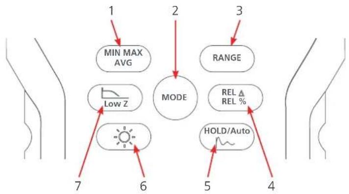
flowchart
graph TD
    A["1"] --> B["MIN MAX AVG"]
    B --> C["MODE"]
    C --> D["RANGE"]
    C --> E["REL REL %"]
    E --> F["HOLD/Auto"]
    style A fill:#f9f,stroke:#333
    style B fill:#ccf,stroke:#333
    style C fill:#cfc,stroke:#333
    style D fill:#fcc,stroke:#333
    style E fill:#cff,stroke:#333
    style F fill:#ffc,stroke:#333
| No. Description Available (Function | Dial) | |
| 1 Record minimum, maximum or average values, shown on the Secondary display. Step through MIN, MAX and AVG readings Press and hold for two seconds to cancel | VAC, VDC AAC, ADC, Hz, Ω, Capacitor and Temperature measurement | |
| 2 Toggle through the available options at a selected function (see 4.3 Function Dial (page 13)) | All positions | |
| 3 Select automatic or manual range (see 5.4 Range Selection (page 16)) | VAC, VDC AAC, ADC, Hz, Ω and Capacitor measurement | |
| 4 REL Δ: Captures the current reading and shows it as a reference for subsequent readings on the Secondary display. The Primary display is the difference between the stored reading and subsequent readings REL %: Captures the current reading and shows it as a reference for subsequent readings on the Secondary display. The Primary display is a percentage of subsequent readings to stored reading Press and hold for two seconds to cancel | VAC, VDC AAC, ADC, Hz, Ω, Capacitor and Temperature measurement | |
| 5 HOLD: Capture the current reading and show the value on the Secondary display. The Primary display shows subsequent readings HOLD/Auto: Capture the current reading on the Secondary display. When a new stable reading is detected, the instrument beeps and shows the new reading Smooth: Measurements are refreshed every two seconds and shown on the Primary display Press and hold for two seconds to cancel | VAC, VDC AAC, ADC, Hz, Ω, Capacitor and Temperature measurement | |
| 6 Backlight: Set the backlight On / Off (automatically goes Off after one minute) | All positions | |
| 7 Low Z: Reduce the input impedance down to 10 KOhms during voltage and capacitance measurement In LPF (Low Pass Filter) mode the instrument continues to measure in the selected AC mode, but the signal diverts through a filter, which blocks unwanted voltages above 800 Hz | VAC, VDC, Capacitance | |
4.3 Function Dial

■ White symbols: Default function
■ Yellow symbols: Other functions
Press

repeatedly to select other functions.
No. Function
| 1 6.4 Resistance Measurement (page 20)6.5 Continuity Test (page 22)6.6 Conductance Measurement (page 23) |
| 2 6.7 Capacitance Measurement (page 24)6.8 Diode Test (page 26). Measure the forward voltage drop across PN junction of diode and transistor |
| 3 6.9 Frequency Measurement (page 28) |
| 4 6.10 Temperature Measurement (page 29) |
| 5 6.11 AC Voltage Detection (page 30)Detects live AC circuit in vicinity (Hi or Lo sensitivity) |
| 6 6.12 Current Measurement (page 31)AC measurements 0.0 A to 10.00 ADC measurements 0.0 A to 10.00 AAC Frequency |
| 7 Milliampere 6.12 Current Measurement (page 31)AC measurements 0.0 mA to 100.00 mADC measurements 0.0 mA to 100.00 mAAC frequency |
| 8 Instrument Off (battery power Off)APO is active by default (see Auto Power Off5.5 Backlight (page 16)) |
| 9 6.2 Voltage Measurement (page 18)AC, DC, or AC+DC |
| 10 6.3 Phase Rotation / Sequence Detection (page 19)Phase sequence detection of three phase AC supply |
4.4 Terminals
For user safety it is important to:
■ Always connect the common (COM) probe first and then connect the live probe to the circuit or the instrument
■ Always remove the live probe first and then remove the common (COM) probe

No. Description Details
1 V Voltage, Resistance, Diode Capacitance and Voltage Frequency
2 10 A ≤ 10 A current measurements and frequency
3 100 mA ≤ 100 mA current measurements and frequency
4 COM Return (Common)
4.5 Display
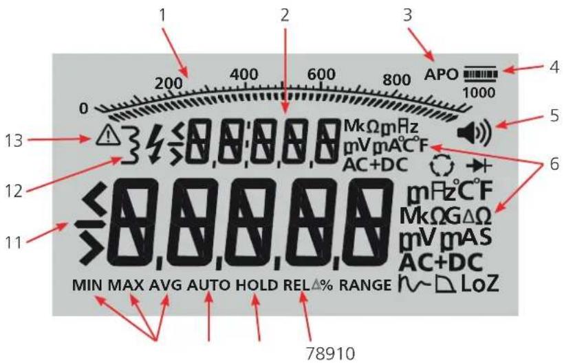
No. Description
1 Analogue arc consist of linear scale and 53 needles
2 Secondary display
3 Auto Power Off (APO) active
4 Shows battery charge at 100%, 75%, 50% and 25%. Once the battery charge goes below 25%, the icon flashes to show that new batteries must be installed
5 Beep On
6 Primary and secondary display mode symbols
7 Relative function active
8 Hold active. If HOLD flashes, Auto Hold is active
9 Range: Auto shows when Auto range is selected.
10 Minimum, Maximum or Average modes
11 Primary display
12 Non-contact AC detection On.
13 Caution, hazardous condition
NOTE : Note: If OL shows on the display it means that the current reading is over range.
5. Start-up Overview
5.1 Start-up and Shut-down
■ To start and use the instrument rotate the Function Dial to a function
- On start-up the instrument completes a self test routine before normal operation
■ To shut-down rotate the Function Dial to Off
5.2 Auto Power Off (APO)
Auto Power Off (APO) is active by default. After 10 minutes of inactivity the instrument will go into a sleep mode.
To recover from sleep mode press any button or rotate the Function Dial to an adjacent function (the display for the selected function shows). All previously activated button features (MIN, MAX, AVG, HOLD, and so on) are discarded.
To Disabled APO
MODE
- Press and hold
- Rotate the Function Dial to a function.
NOTE : Note: APO is also disabled in MIN, MAX and AVG mode.
5.3 Battery Status
When the battery icon flashes (25% battery life left) the batteries need to be replaced.
When BAT LOW shows on the display the instrument will not respond to user requests and will eventually shutdown. Replace the batteries.
See To Replace the Batteries (page 35).
5.4 Range Selection
Select automatic or manual ranges (default: automatic). When set to automatic, the instrument automatically selects the range with best resolution.
To Set to Manual Range
- Press and release RANGE, to toggle through the available ranges.
- Press and hold RANGE to return to AUTO range (AUTO shows on the display).
5.5 Backlight
Press 🙏 to set the backlight On or Off. The backlight automatically goes Off after one minute.
6. Measurements
This section details all the available measurements on the instrument.
For user safety it is important to:
■ Always connect the common (COM) probe first and then connect the live probe to the circuit or the instrument.
■ Always remove the live probe first and then remove the common (COM) probe.
Measurement modes that the not designed to measure live circuits will sound a continuous audible beep and show V OL (flashing) on the display. Measurement is inhibited.
Test leads must immediately be disconnected from the circuit under test.
Measurements
6.2 Voltage Measurement
The instrument features true RMS measurement, which gives accurate readings for distorted sine waves and other waveforms such as square waves, triangle waves, and staircase waves.


Fig 1: Voltage Measurement Set-up
No. Description
1 AC voltage set-up
2 DC voltage set-up
To Measure Voltage
- Set-up the instrument as shown in Fig 1.
■ Set the Function Dial to +dcV
■ Red test lead: V terminal
■ Black test lead: COM terminal
- Press ∪ to toggle through:
AC (default)
DC
AC + DC
- If manual range is required, press RANGE repeatedly to scroll to a suitable range and resolution. Press and hold RANGE to return to AUTO range (AC and DC modes only).
Low Impedance Voltage Measurements: For AC Voltage measurements on cables with ghost voltage, press (low input impedance) mode. LoZ will show on the display.
6.2.1 AC+DC Description
The AC+DC function is used to measure complex voltages, which consist of both AC and DC components.
$$ V _ {A C + D C} = \sqrt {(V _ {A C} ^ {2} + V _ {D C} ^ {2})} $$
Therefore:
Where VAC = 230 V and VDC = 85 V
Addition of AC and DC voltages give 315 V.
However:
$$ \begin{array}{l} V _ {A C + D C} = \sqrt {\left(V _ {A C} ^ {2} + V _ {D C} ^ {2}\right)} \ = \sqrt {(2 3 0 ^ {2} + 8 5 ^ {2})} \ = \sqrt {(6 0 1 2 5)} \ = 2 4 5. 2 0 \mathrm{VTRMS} \ \end{array} $$
6.3 Phase Rotation / Sequence Detection
Phase Rotation / Sequence Detection enables the connection of three phase power to the motor or any three phase appliance in correct sequence.
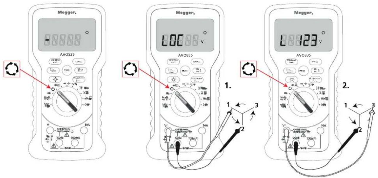
Fig 2: Phase Rotation / Sequence Detection Set-up
For a valid detection, set the voltage level and supply frequency to:
ACV: > 80 V
■ Supply Frequency: In the range 40 Hz to 80 Hz.
Measurements
To Detect Phase Rotation / Sequence
- Set-up the instrument as shown in Fig 2.
■ Set the Function Dial to
■ Red test lead: V terminal
■ Black test lead: COM terminal
-
The range locks to 1000 V and ---- shows on the Primary display.
-
Connect the V and COM probes to L1 and L2 phases of the three phase supply (1).
-
If the voltage and frequency are correct the instrument shows LOC on the Primary display.
-
Once LOC shows change L1 to third phase (L3) within eight seconds (2).
-
If phase changeover is not detected within eight seconds t-OUT (Time Out) shows on the Primary display.
-
If phase changeover is detected within eight seconds, the phase sequence result will show as:
■ L1 L2 L3 (phase sequence is OK / Forward), or
L3 L2 L1 (phase sequence is NOT OK / Reverse)
- After three seconds test will start again on its own.
6.4 Resistance Measurement
To measure resistance a small current is sent through the circuit to be tested. Because this current flows through all possible paths between the test probes, the resistance reading represents the total resistance of all paths between the test probes. Therefore to measure the resistance of:
A Resistor: Disconnect at least one connection (1)
A Variable resistor: Disconnect at least two connections (2)

Fig 3: Resistance Measurement Set-up
CAUTION : Caution: To avoid possible damage to the instrument or to the equipment under test, make sure that the circuit power is disconnected and all high-voltage capacitors are discharged before resistance is measured.
To Measure Resistance
- Make sure that:
■ The circuit power is disconnected
■ All high-voltage capacitors are discharged
NOTE : Note: If a live circuit is detected the instrument will sound a pulsed audible beep and V OL (flashing) shows on the display.
-
Set-up the instrument as shown in Fig 3.
-
Set the Function Dial to
■ Red test lead: V terminal
■ Black test lead: COM terminal -
If manual range is required, press RANGE repeatedly to scroll to a suitable range and resolution. Press and hold RANGE to return to AUTO range.
-
Connect the test probe tips to the circuit under test.
The display shows 0L until a circuit is detected and shows the appropriate resistance when the circuit is detected.
6.4.1 Resistance Measurement Tips
The measured value of a resistor in a circuit is often different from the actual value of the resistor
Test probes can add 0.1 Ω to 0.2 Ω of error to resistance measurements. To test this resistance, touch the probe tips together and read the resistance of the test probes. If required, press REL % to automatically subtract this value
The resistance function can produce enough voltage to forward-bias silicon diode or transistor junctions, causing them to conduct. If this is suspected, press RANGE to apply a lower current in the next higher range
6.5 Continuity Test
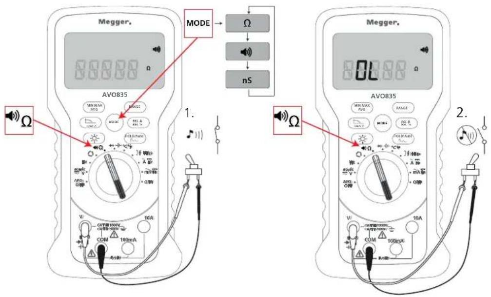
Fig 4: Continuity Test Set-up
No. Description
1 Closed Circuit (audible beep)
2 Open circuit (no audible beep)
CAUTION : Caution: To avoid possible damage to the instrument or to the equipment under test, make sure that the circuit power is disconnected and all high-voltage capacitors are discharged before a continuity test.
To Detect Any Open or Short Circuits
- Make sure that:
■ The circuit power is disconnected
■ All high-voltage capacitors are discharged
NOTE : Note: If a live circuit is detected the instrument will sound a pulsed audible beep and V OL (flashing) shows on the display.
-
Set-up the instrument as shown in Fig 4.
-
Set the Function Dial to .
■ Red test lead: V terminal
■ Black test lead: COM terminal

3. Connect the test probes to the cable or circuit under test.
The Primary display shows the resistance value and the instrument sounds an audible beep dependant on the resistance:
| Resistance Beep mode |
| ≤5 Ω Continuous beep |
| <5 Ω to <50 Ω Intermittent beep |
| ≥50 Ω No beep |
The continuity function can detect intermittent open and short circuits, which last as little as 10 ms
6.6 Conductance Measurement
Conductance, the inverse of resistance, is the ability of a circuit to pass current. High values of conductance correspond to low values of resistance.
The instrument's 1 nS to 60 nS range measures conductance with resolution of 0.01 nS. Because such small amounts of conductance correspond to extremely high resistance, the nS range can determine the resistance of components up 1 GΩ.
A current flows through all possible paths between the test probes, the conductance reading represents the total conductance of all paths between the test probes. Therefore to measure the conductance of:
A Resistor: Disconnect at least one connection (1)
A Variable resistor: Disconnect at least two connections (2)

Fig 5: Conductance Measurement Set-up
Measurements
CAUTION : Caution: To avoid possible damage to the instrument or to the equipment under test, make sure that the circuit power is disconnected and all high-voltage capacitors are discharged before conductance is measured.
To Measure Conductance
1. Make sure that:
■ The circuit power is disconnected
■ All high-voltage capacitors are discharged
NOTE : Note: If a live circuit is detected the instrument will sound a pulsed audible beep and V OL (flashing) shows on the display.
2. Set-up the instrument as shown in Fig 5.
■ Set the Function Dial to Ω
MODE
Press twice to select n S
■ Red test lead: V terminal
■ Black test lead: COM terminal
3. Connect the test probe tips to the circuit under test.
The display shows 0.00 nS until the circuit is detected and shows the appropriate conductance when the circuit is detected.
6.7 Capacitance Measurement
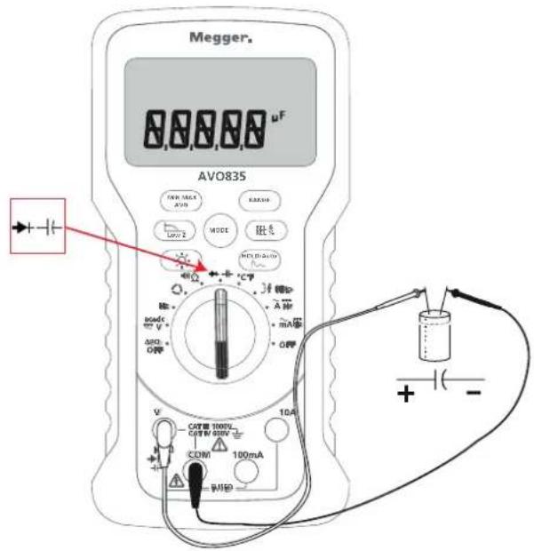
Fig 6: Capacitance Measurement Set-up
CAUTION : Caution: To avoid possible damage to the instrument or to the equipment under test, make sure that the circuit power is disconnected and all high-voltage capacitors are discharged before capacitance is measured. Use the DC voltage function to confirm that the capacitor is discharged.
To Measure Capacitance
- Make sure that:
■ The circuit power is disconnected
■ All high-voltage capacitors are discharged
NOTE : Note: If a live circuit is detected the instrument will sound a pulsed audible beep and V OL (flashing) shows on the display.
-
Set-up the instrument as shown in Fig 6.
-
Set the Function Dial to
■ Red test lead: V terminal
■ Black test lead: COM terminal
Once the test probes are connected to the capacitor the capacitance is shown on the Primary display.
NOTE : Note: This can take a few seconds on large capacitance.
6.7.1 Smart Capacitance
Patent applied for.
When the test leads are connected to a capacitor, which has a residual charge, the live circuit is enabled.
The Smart Capacitance function monitors the charge status of the capacitor, when the charge status reaches a safe level the instrument will then do a capacitance measurement.
6.8 Diode Test
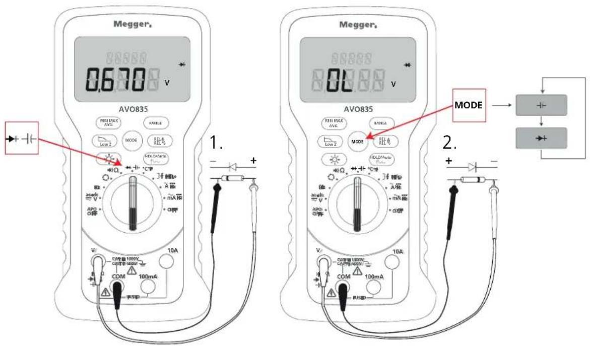
Fig 7: Diode Test Set-up
No. Description
1 Forward Bias
2 Reverse Bias
CAUTION : Caution: To avoid possible damage to the instrument or to the equipment under test, make sure that the circuit power is disconnected and all high-voltage capacitors are discharged before diode tests are started.
To Test a Diode
- Make sure that:
■ The circuit power is disconnected
■ All high-voltage capacitors are discharged
NOTE : Note: If a live circuit is detected the instrument will sound a pulsed audible beep and V OL (flashing) shows on the display.
- Set-up the instrument as shown in Fig 7 for forward or reverse bias.
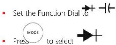
3. Connect the test probe tips to the diode.
The Primary display shows the forward voltage drop (Fig 8).
■ The display shows OL (out of range) if the diode is open (3 (fault open circuit)).
■ If diode is short circuit an audible beep will sound (4 (fault short circuit))

Fig 8: Forward Voltage Drop Across Semi-conductor Junction
Measurements
6.9 Frequency Measurement
To measure the frequency of a voltage signal the instrument counts the number of times the signal crosses a threshold level each second.

Fig 9: Frequency Measurement Set-up
To Measure Frequency
- Set-up the instrument as shown in Fig 9.
Hz
-
Set the Function Dial to
■ Red test lead: V terminal
■ Black test lead: COM terminal -
Connect the test probe tips to the circuit under test.
The Primary display shows the frequency in Hz.
- If manual range is required, press RANGE repeatedly to scroll to a suitable range and resolution. Press and hold RANGE to return to AUTO range.
6.10 Temperature Measurement

Fig 10: Temperature Measurement Set-up
To Measure Temperature
WARNING: ⚠️ Warning: To avoid the risk of electric shock do not connect the thermocouple to circuits greater than 10 V.
The instrument measures the temperature of a type-K thermocouple.
-
Set-up the instrument as shown in Fig 10.
-
Set the Function Dial to ^ C ^ F .
- Temperature Measurement Probe '+': V terminal
Temperature Measurement Probe '-': COM terminal Press MODE to toggle between °C or °F.
OL shows on the Primary display if:
■ The reading is out of range, or
A sensor is disconnected or open circuit
6.11 AC Voltage Detection
To detect AC voltage, the top of the instrument must be placed close to a live conductor.
The instrument gives an audible, as well as a visual, indication when voltage is detected.
CAUTION : Caution: If there is no voltage indication, voltage could still be present. Do not rely on this detection when used in the vicinity of shielded wire. Operation may be effected by differences in socket design, insulation thickness and type.

Fig 11: AC voltage Detection Set-up
There are two sensitivity settings:
To Check the Presence of AC Voltage
- Set-up the instrument as shown in Fig 11.
■ Set the Function Dial to 34
- Place the instrument close to a live conductor.
MODE 3. Press to select:
■ HI: (default) Highest sensitivity to AC voltage
■ LO: Low sensitivity to AC voltage
6.12 Current Measurement
CAUTION : Caution: To avoid possible damage to the instrument or to the equipment under test:
- Check the instrument's fuses before a current is measured
■ Use the correct terminals, function, and range for all measurements
■ Never place the test probes across (in parallel with) any circuit or component when the test probes are plugged into the current terminals
NOTE : Note: To produce a positive reading connect the black test probe to the negative side of the circuit and connect the red test probe to the positive side of the circuit. If the test probes are reversed it will produce a negative reading, but will not damage the instrument. AC current measurement is selected by default. Press MODE to toggle through AC or DC measurements.
6.12.1 Ampere Measurement
WARNING : Warning: To avoid possible electric shock or personal injury never attempt an in-circuit current measurement, where the open-circuit potential to earth is greater than 1000 V. You may damage the instrument or be injured if the fuse blows during such a measurement.

Fig 12: ≤ 10 A Measurement Set-up
6.12.2 To Measure AC or DC current ≤ 10 A
CAUTION : Caution: To avoid blowing the instrument's 100 mA fuse, use the mA terminal only if the current is continuously less than 100 mA.
- Set-up the instrument as shown in Fig 12.
Set the Function Dial to =Hz .
■ Red test lead: 10 A terminal
■ Black test lead: COM terminal
MODE
- Press to toggle AC (default) or DC measurement
- Set the circuit power to Off.
- Make sure that high voltage capacitors are discharged.
- Connect the test leads in circuit
- Set the circuit power to On.
- If manual range is required, press RANGE repeatedly to scroll to a suitable range and resolution. Press and hold RANGE to return to AUTO range.
- Once the reading is done, disconnect the supply before the test probes are removed.
6.12.3 Milliampere Measurement
WARNING: Warning: To avoid possible electric shock or personal injury never attempt an in-circuit current measurement, where the open-circuit potential to earth is greater than 1000 V. You may damage the instrument or be injured if the fuse blows during such a measurement.
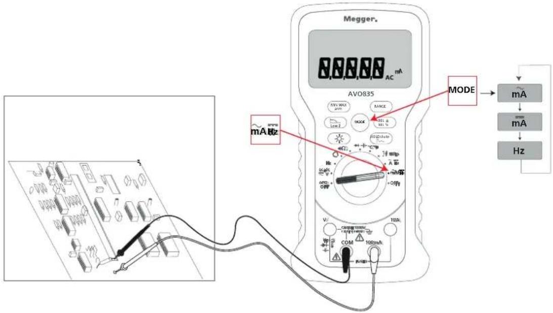
Fig 13: ≤ 100 mA Measurement Set-up
To Measure AC or DC current ≤ 100 mA
CAUTION : Caution: To avoid blowing the instrument's 100 mA fuse, use the mA terminal only if the current is continuously less than 100 mA.
- Set-up the instrument as shown in Fig 13.
mA Hz
■ Set the Function Dial to
■ Red test lead: 100 mA terminal
■ Black test lead: COM terminal
-
Press MODE to toggle AC (default) or DC measurement
-
Set the circuit power to Off.
-
Make sure that high voltage capacitors are discharged.
-
Connect the test leads in circuit
-
Set the circuit power to On.
-
Once the reading is done, disconnect the supply before the test probes are removed.
Measurements
To Measure the Frequency of the Current from Amp and mA Input
- Repeat the procedure for 10 A or 100 mA.

-
Press to toggle through AC, DC and Hz.
-
Make sure that Hz is shown on the display.
-
Three ranges are available (100 Hz, 1 KHz and 10 KHz).
-
If manual range is required, press RANGE repeatedly to scroll to a suitable range and resolution. Press and hold RANGE to return to AUTO range.
7. Maintenance
For instrument calibration and calibration intervals, which includes any test equipment required, refer to instrument Service Manual.
These instruments contain no user repairable parts and if defective should be returned to your supplier in the original packaging or packed so that it is protected from damage during transit. Damage in transit is not covered by this warranty and replacement / repair is chargeable (see 11. Repair and Warranty (page 44))
7.1 Batteries
WARNING: Warning: To avoid false readings, which could lead to possible electric shock or personal injury, replace the batteries as soon as the battery indicator starts to flash.
CAUTION : Caution: Do not mix used batteries with general waste stream. Use a qualified recycler or hazardous material handler to dispose of used batteries.
CAUTION : Caution: Always set the instrument to Off and remove the test leads before the batteries are removed and installed. Only use approved batteries.
Approved batteries (see 10.1 General Specifications (page 40).
7.1.1 Battery Status
When the battery icon flashes (25% battery life left) the batteries need to be replaced.
When LOW BAT shows on the display the instrument will not respond to user requests and will eventually shutdown. Replace the batteries
7.2 Battery Replacement
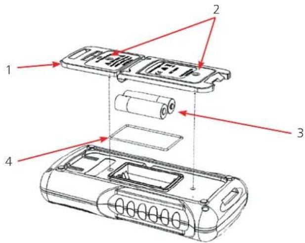
Fig 14: Battery Replacement
To Replace the Batteries
- Set the Function Dial to Off.
- Remove the test probes from the terminals.
- Use a flat blade screwdriver to loosen the two captive screws (2). Remove the battery cover (1).
- Replace the batteries (3).
- Install the battery cover. Make sure that the gasket (4) is correctly seated. Tighten the two battery cover screws clockwise to secure.
- Dispose of old batteries (see 8.2 Battery Disposal (page 38)).
7.3 Fuse Replacement
CAUTION : Caution: To avoid personal injury or damage to the instrument, install only approved fuses (see 9. Accessories (page 39).
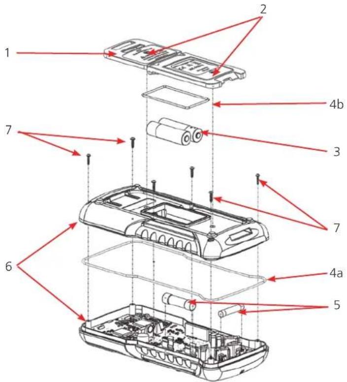
Fig 15: Fuse Replacement
To Replace Fuses
- Set the Function Dial to Off.
- Remove the test probes from the terminals.
- Use a flat blade screwdriver to loosen the two captive screws. Remove the battery cover.
- Remove the batteries.
- Remove the 6 Phillips-head screws from the case bottom (7).
- Part the two halves of the case (6).
NOTE : Tip: Gently push down on the battery terminal connected to the PCB from inside the battery compartment to help separate the two halves of the case.
- Replace the fuse or fuses (5). Gently lever one end loose, and slide the fuse out of its clip.
- Use specified replacement fuses only (see 9. Accessories (page 39).
- Put the two case halves together. Make sure that the gasket (4a) is correctly seated and that the case halves snap together around the all edges.
- Must use the 6 original screws provided by the manufacturer to secure the two case halves together. Do not over tighten. The screws provided by the manufacturer must be used.
- Install the batteries.
- Install the battery cover. Make sure that the gasket (4b) is correctly seated. Tighten the two battery cover captive screws to secure.
7.4 Clean the instrument
CAUTION : Caution: Do not use abrasives, isopropyl alcohol or solvents to clean the case or lens/ window. These substances can damage the case materials.
■ Cleaning interval: As required
■ The instrument should be kept free of dust and liquids
■ Dirt or moisture in the terminals can affect readings
■ Wipe the case with a damp cloth and mild detergent
7.5 Technical Support
For technical support go to the Megger technical support site (uk.megger.com/support). See the exhaustive FAQs, technical support documents and information about After Sales support.
Alternatively:
■ Call +44 (0) 1304 502101 (After Sales support), or
■ Submit a completed After Sales Support form (see uk.megger.com/support/after-sales-support).
8. End of Life Disposal
8.1 WEEE Directive

Do not dispose of the product with normal waste at the end of its life.
Megger is registered in the UK as a Producer of Electrical and Electronic Equipment (Reg No.: WEE/HE0146QT).
For more information about the disposal of this product contact your local Megger company / distributor or go to your local Megger website.
8.2 Battery Disposal
Do not dispose of batteries with normal waste at the end of their life.
This product uses these types of batteries:
■ AA size alkaline (LR6), or
NiMH (HR6)
See To Replace the Batteries (page 35), for location and how to safely replace the instrument batteries.
Dispose of batteries as per your local authority regulations.
Megger is registered in the UK as a Producer of Batteries (Reg No.: BPRN00142).
For more information go to www.megger.com.
9. Accessories
9.1 Optional and Replacement Accessories
| Part Description Quantity Part Number | |
| Battery AA size alkaline (LR6) 2 1009-215 | |
| NiMH (HR6) 2 1009-214 | |
| Fuse 11 A 1000 V 30 kA (10 mm x 38 mm) 1 1009-213 | |
| Fuse FF 0.125 mA 1000 V 30 kA (6.3 mm x 32 mm) 5 1009-212 | |
| Test Lead Kit (not fused) x2 leads (black/red) x2 crocodile clips (black/red) | 1 1002-001 |
| Test Lead Kit (500 mA) x2 leads (black/red) x2 long probes (black/red) | 1 1002-015 |
| Thermocouple Sensor (AVO835 only) 1 1010-461 | |
| Magnetic Hanger | 1 1010-013 |
10. Specifications
This section covers general and technical specifications for this instrument.
10.1 General Specifications
The instrument complies with these standards:
IEC/EN 61010-1
IEC/EN 61010-2-033
IEC/EN 61326-1
Item Value
| Maximum voltage between any terminal and ground (earth) 1000 Vrms (AVO835), 600 Vrms (AVO830) | |
| Surge Protection 8 kV Peak (IEC/EN-61010-1) | |
| Fuse protection for mA Input FF 0.125 A, 30 kA @1000 V Fuse | |
| Fuse protection for A Input 11 A, 30 kA @1000 V Fuse | |
| Primary display 10000 counts | |
| Secondary display 10000 counts | |
| Analogue Arc 53 segments | |
| Working Temperature -10 °C to +50 °C (14 °F to 122 °F) | |
| Storage Temperature | -30 °C to +70 °C (-22 °F to 158 °F) |
| Working Relative Humidity | ≤ 90 % at 40 °C (104 °F) |
| Storage Relative Humidity | ≤ 50 % at 60 °C (140 °F) |
| Altitude rating | 2000 m (6561.5 ft) |
| Battery | x2 AA Alkaline (LR6) or x2 NiMH (HR6) |
| Battery life | 150 hours (without backlight) |
| IP Rating (dust and water protection) | IP54 Category 2 |
10.2 Technical Specifications
For all detailed specifications, the accuracy is given as +/- ([% of reading] + [number of least significant digits]) at 18 °C to 28 °C (64°F to 82°F), with relative humidity up to 90 %, for a period of one year after calibration.
Voltage (DC)
Range AVO830 - 1.0000 V, 10.000 V, 100.00 V, 600.0 V
AVO835 - 1.0000 V, 10.000 V, 100.00 V, 1000.0 V
Accuracy ±0.1% +2
Input resistance 10 MΩ / 10 KΩ
Voltage (AC)
Range AVO830 - 1.0000 V, 10.000 V, 100.00 V, 600.0 V
AVO835 - 1.0000 V, 10.000 V, 100.00 V, 1000.0 V
Accuracy 45 Hz - 500 Hz ±1.0% +3 500 Hz - 1 kHz ±2.0% +3 1 kHz - 5 kHz ±3.0% +3
Input resistance 10 MΩ / 10 KΩ
Current measurement (DC)
Range 100.00 mA, 1.0000 A, 10.000 A
Accuracy ±1.0% +3
Current measurement (AC)
Range 100.00 mA, 1.0000 A, 10.000 A
Accuracy 45 Hz - 500 Hz ±1.5% +10 500 Hz - 1 kHz ±2.0% +20
Phase rotation
Range 95 V - 440 V
Resistance measurement
Range 100.00 Ω, 1.0000 kΩ, 10.000 kΩ, 100.00 kΩ, 1.0000 MΩ, 10.000 MΩ, 50.00 MΩ
Accuracy 0.1 Ω - 6 MΩ ±1.0% +2 6 MΩ - 50 MΩ ±2.0% +2
Conductance
Range / resolution 1nS - 60.00 nS / 0.01 nS
Accuracy ±1.5% +10
Specifications
Continuity measurement
Range / resolution 100.00 Ω / 0.01 Ω
Buzzer ON ≤5 Ω
Buzzer Intermittent >5 <50 Ω
Buzzer off ≥50 Ω
Frequency measurement
Range/resolution 100.00 Hz / 0.01 Hz
1.0000 kHz / 0.0001 kHz
10.000 kHz / 0.001 kHz
100.00 kHz / 0.01 kHz
Accuracy ±0.1% +2
Capacitance measurement
Range / resolution 10.000 uF / 0.001 uF
100.00 uF / 0.01 uF
1.0000 mF / 0.0001 mF
10.000 mF / 0.001 mF
20.00 mF / 0.01 mF
Accuracy ±2.0% +2
±5% +10 (> 1000 μF)
Diode test
Range / resolution 0 V + 2.800 V / 0.001 V
Accuracy ±1.0% +2
Temperature
Type (AVO835 Only) K
Range / resolution (AVO835 Only) -20 °C to +1000 °C / 0.1°
Accuracy (AVO835 Only) ±1.0 °C +20
Environmental
Operational Temperature -10 °C to +50 °C (14 °F to 122 °F)
Operational Relative Humidity ≤ 90 % at 40 °C (104 °F)
Storage Temperature -30 °C to +70 °C (-22 °F to 158 °F)
Storage Relative Humidity ≤ 50 % at 60 °C (140 °F)
Altitude rating 2000 metres (6561.5 ft)
IP rating IP54 Category 2
Battery life (w/o backlight) 150 hours
Automatic Stop 10 Min.
Other features
Display count 10000
IEC IEC 61010
Safety rating AVO830 - CAT IV 600 V
AVO835 - CAT III 1000 V / CAT IV 600 V
Dimensions 200 x 100 x 38 mm
Weight 430 g
11. Repair and Warranty
If the protection of an instrument has been impaired it should not be used, but sent for repair by suitably trained and qualified personnel. The protection is likely to be impaired if, for example, the instrument shows visible damage, fails to perform the intended measurements, has been subjected to prolonged storage under unfavourable conditions, or has been exposed to severe transport stresses.
New instruments are covered by a three year warranty from the date of purchase by the user, the second and third year being conditional on the free registration of the product at www.megger.com. You will need to log in, or first register and then login to register your product. The second and third year warranty covers faults, but not recalibration of the instrument which is only warranted for one year. Any unauthorised prior repair or adjustment will automatically invalidate the warranty.
These products contain no user repairable parts and if defective should be returned to your supplier in the original packaging or packed so that it is protected from damage during transit. Damage in transit is not covered by this warranty and replacement / repair is chargeable.
Megger warrants this instrument to be free from defects in materials and workmanship, where the equipment is used for its proper purpose. The warranty is limited to making good this instrument (which shall be returned intact, carriage paid, and on examination shall disclose to their satisfaction to have been defective as claimed).
Misuse of the instrument, from connection to excessive voltages, fitting incorrect fuses, or by other misuse is excluded from the warranty.
The instrument calibration is warranted for one year.
This Warranty does not affect your statutory rights under any applicable law in force, or your contractual rights arising from a sale and purchase contract for the product. You may assert your rights at your sole discretion.
11.1 Calibration, Service and Spare Parts
For service requirements for Megger instruments contact Megger or your local distributor or an authorised repair centre. Megger operates fully traceable calibration and repair facilities, ensuring your instrument continues to provide the high standard of performance and workmanship you expect. These facilities are complemented by a worldwide network of approved repair and calibration companies to offer excellent in-service care for your Megger products.
Refer to Megger contact details.
Local Sales office
Megger Limited
Archcliffe Road
Dover
Kent
CT17 9EN
ENGLAND
T.+44(0)1304502101
F. +44 (0)1 304 207342
Manufacturing sites
| Megger LimitedArchcliffe RoadDoverKentCT17 9ENENGLANDT. +44 (0)1 304 502101F. +44 (0)1 304 207342 | Megger GmbHWeststraße 5952074 AachenT. +49 (0) 241 91380 500E. info@megger.de | Megger USA - Valley ForgeValley Forge Corporate Center2621 Van Buren AvenueNorristownPennsylvania, 19403USAT. +1 610 676 8500F. +1 610 676 8610 |
| Megger USA - Dallas4545 West Davis StreetDallas TX 75237USAT. 800 723 2861 (USA only)T. +1 214 333 3201F. +1 214 331 7399E. USsales@megger.com | Megger ABRinkebyvägen 19, Box 724, SE-182 17DANDERYDT. +46 08 510 195 00E. seinfo@megger.com | Megger USA - Fort Collins4812 McMurry AvenueSuite 100Fort Collins CO 80525USAT. +1 970 282 1200 |
This instrument is manufactured in the United Kingdom.
The company reserves the right to change the specification or design without prior notice.
Megger is a registered trademark
The Bluetooth® word mark and logos are registered trademarks owned by Bluetooth SIG, Inc and is used under licence.
AVO830--AVO835_UG_en_V03 11 2021
© Megger Limited 2021 www.megger.com

- This document is copyright of:
- Declaration of Conformity
- Overview......6
- Safety 7
- Introduction....10
- Product Features....11
- Start-up Overview....16
- Measurements....17
- Maintenance....35
- End of Life Disposal....38
- Accessories....39
- Specifications....40
- Repair and Warranty....43
- Figures
- Overview
- Contact Megger UK
- Safety
- Safety Information
- Safety
- Measurement Connection
- Voltage
- CAT IV
- CAT III
- CAT II
- Warnings, Cautions and Notes
- Warnings
- Cautions
- Notes
- Safety and Hazard Symbols
- Introduction
- Measurement Functions
- Product Features
- Overview
- No. Details
- Function Buttons
- Function Dial
- Terminals
- No. Description Details
- Display
- No. Description
- Start-up Overview
- Start-up and Shut-down
- Auto Power Off (APO)
- To Disabled APO
- Battery Status
- Range Selection
- To Set to Manual Range
- Backlight
- Measurements
- Measurements
- Voltage Measurement
- To Measure Voltage
- AC+DC Description
- Therefore:
- However:
- Phase Rotation / Sequence Detection
- To Detect Phase Rotation / Sequence
- Resistance Measurement
- To Measure Resistance
- Resistance Measurement Tips
- Continuity Test
- To Detect Any Open or Short Circuits
- Connect the test probes to the cable or circuit under test.
- Conductance Measurement
- To Measure Conductance
- Make sure that:
- Set-up the instrument as shown in Fig 5.
- Connect the test probe tips to the circuit under test.
- Capacitance Measurement
- To Measure Capacitance
- Smart Capacitance
- Diode Test
- To Test a Diode
- Connect the test probe tips to the diode.
- Frequency Measurement
- To Measure Frequency
- Hz
- Temperature Measurement
- To Measure Temperature
- AC Voltage Detection
- To Check the Presence of AC Voltage
- Current Measurement
- Ampere Measurement
- To Measure AC or DC current ≤ 10 A
- Milliampere Measurement
- To Measure the Frequency of the Current from Amp and mA Input
- Maintenance
- Batteries
- Battery Status
- Battery Replacement
- To Replace the Batteries
- Fuse Replacement
- To Replace Fuses
- Clean the instrument
- Technical Support
- End of Life Disposal
- WEEE Directive
- Battery Disposal
- Accessories
- Optional and Replacement Accessories
- Specifications
- General Specifications
- Technical Specifications
- Voltage (DC)
- Voltage (AC)
- Current measurement (DC)
- Current measurement (AC)
- Phase rotation
- Resistance measurement
- Conductance
- Specifications
- Continuity measurement
- Frequency measurement
- Capacitance measurement
- Diode test
- Temperature
- Environmental
- Other features
- Repair and Warranty
- Calibration, Service and Spare Parts
- Local Sales office
Brand : Megger
Model : AVO830
Category : Multimeter