
WastePro WPS1260 - Waste Management Equipment Hobart - Free user manual and instructions
Find the device manual for free WastePro WPS1260 Hobart in PDF.


| Brand | Hobart |
| Model | WastePro WPS1260 (ML-130287) |
| Category | Waste Equipment System |
| Type | Pulper and Waterpress |
| Pulper Motor Power | 6 hp |
| Waterpress Motor Power | 2 hp |
| Return Pump Motor Power | 3 hp |
| Total Motor Power | 11 hp |
| Electrical Supply | 208-240V, 60Hz, 3-phase (refer to data plate) |
| Water Supply Pressure | 25-45 psig flowing |
| Water Inlet Connections | 1/2" NPT cold and hot |
| Drain Connections | 2" pulper drain, 1 1/2" waterpress overflow |
| Max Feed Rate | 60 lbs per 3 minutes |
| Construction Material | Stainless steel |
| Chemical Feeder | Standard, adjustable pump |
| Vibration Isolation | Footpads included |
| Safety Features | Pulper cover interlock, discharge chute interlock |
| Cleaning Method | Daily with hot water, hose, and mild detergent |
| Maintenance Interval | Check oil every 3 months |
| Recommended Oil | Mobil Gear Oil #629 (Hobart Part 103881-72) |
| Optional Accessories | Silver saver, magnet, trough flush, feed tray |
| Service | Contact Hobart authorized service |
Frequently Asked Questions - WastePro WPS1260 Hobart
User questions about WastePro WPS1260 Hobart
0 question about this device. Answer the ones you know or ask your own.
Ask a new question about this device
Download the instructions for your Waste Management Equipment in PDF format for free! Find your manual WastePro WPS1260 - Hobart and take your electronic device back in hand. On this page are published all the documents necessary for the use of your device. WastePro WPS1260 by Hobart.
USER MANUAL WastePro WPS1260 Hobart
WPS1260 WastePro TM
WASTE EQUIPMENT SYSTEM
MODEL
WPS1260 ML-130287
HOBART
701 S. RIDGE AVENUE TROY, OHIO 45374-0001
937 332-3000
www.hobartcorp.com
FORM 47601 (June 2016)
TABLE OF CONTENTS
GENERAL 3
INSTALLATION 4
UNPACKING 4
LOCATION 4
VIBRATION ISOLATION FOOTPADS AND LEVELING 4
CHEMICAL FEEDER PUMP 4
THE FOLLOWING PARTS MAY BE INCLUDED (DEPENDING ON OPTIONS SELECTED) ..... 4
SILVER SAVER — BY OTHERS (TROUGH EQUIPPED UNITS ONLY) 5
TROUGH GASKET (TROUGH EQUIPPED UNITS ONLY).... 5
OPTIONAL MAGNET FOR SILVER SAVER (TROUGH EQUIPPED UNITS ONLY) 5
TROUGH PIPING DETAIL (TROUGH EQUIPPED UNITS ONLY)....6
FLANGE DETAIL....6
PULPER INSTALLED UNDER A DISH TABLE....7
PLUMBING CONNECTIONS....8
WATER CONNECTION....8
DRAIN CONNECTION....8
ELECTRICAL CONNECTIONS....8
REMOTE PUSH-BUTTON STATION 9
MOTOR ROTATION 9
ELECTRICAL INSTALLATION 9
OPERATION 10
CONTROLS 10
FEEDING INSTRUCTIONS 11
SHUTDOWN PROCEDURE 12
CLEANING 12
CLEANING INSTRUCTIONS.... 12
CLEANING COMPOUNDS 12
MAINTENANCE....13
MOTORS 13
WATERPRESS DRIVE 13
TROUBLESHOOTING 14
SERVICE 15
Installation, Operation and Care of WPS1260 WastePro™ WASTE EQUIPMENT SYSTEM
SAVE THESE INSTRUCTIONS GENERAL
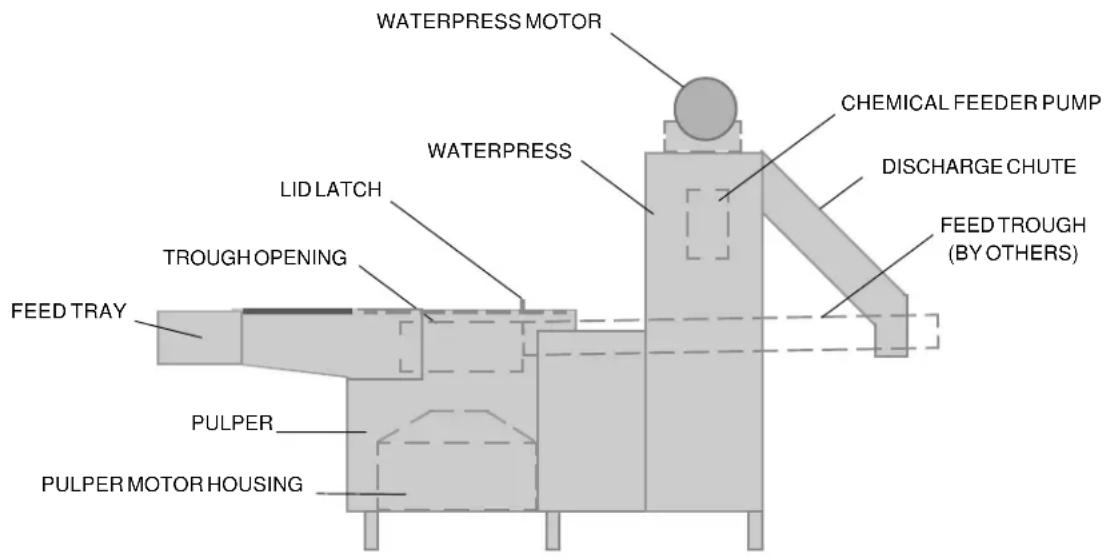
The WPS1260 Waste Equipment System prepares waste materials for disposal using a self-contained pulper and a waterpress. Paper, plastic, foil and food waste are fed into the pulper, shredded into small pieces in water to make a slurry. The waterpress lifts the slurry using a stainless steel screw inside of a perforated tubular screen. The water passes through the screen and is pumped back to the pulper. The solids continue up the screw where they are further compacted to a semi-dry pulp, exiting through the discharge chute to a waste container. Fresh make-up water is supplied to the pulper automatically through a solenoid valve. The original volume of waste material is reduced significantly.
The pulper has a 6 h.p. motor, stainless steel components, carbide and hardened stainless steel shredder blades. The 2 h.p. motor at the waterpress turns the stainless steel screw. A 3 h.p. motor and pump returns the process water to the pulper.
An optional feed tray (by Hobart) allows waste materials to be fed into the pulper. A feed trough (fabricated by tabling suppliers) allows waste materials and water to feed through an optional water-tight opening into the pulper. A flush nozzle with throttling valve (by Hobart) is an available option for the front end of the trough. A silver-saver sink (by others) can be installed in the feed trough; a silver saver magnet is an available option (by Hobart). Mounted below the trough, it restrains ferro-magnetic objects from entering into the pulper.

Fig. 1
INSTALLATION
Prior to installation, test the electrical service to assure that it agrees with the specifications on the machine data plate located on the front of the pulper.
UNPACKING
Immediately after unpacking, check for possible shipping damage. If the unit is found to be damaged, save the packaging material and contact the carrier within 5 days of delivery.
LOCATION
Locate the waste system near a floor drain; floor should be pitched a minimum of 1/4 " per foot to the floor drain. A suitable amount of space should be provided for machine operation, cleaning and service.
VIBRATION ISOLATION FOOTPADS AND LEVELING
Vibration isolation footpads (standard — Fig. 2) must be installed on each of the six legs of the waste system before making connections. Level the units by threading the adjustable feet up or down as necessary.

Fig. 2
CHEMICAL FEEDER PUMP (STANDARD)
The chemical feeder pump is mounted on the waterpress. It has its own on-off switch. When on, the chemical feeder pumps a chemical additive into the waterpress to control odors, to buffer the acidity of the system water and to reduce foaming. Contact your chemical supplier for a recommendation for the appropriate chemical additive. The recommended chemical pump setting is #1 which delivers 0.3 gallons per day. Each subsequent setting number is a direct multiple of setting #1. For example, setting #2 delivers 0.6 gallons per day, etc.
Insert the chemical tube with the plastic filter into the chemical container.
THE FOLLOWING PARTS MAY BE INCLUDED (DEPENDING ON OPTIONS SELECTED)
1 Nozzle for trough flush, rectangular piece has pipe thread with locknut on back.
1 Magnet (option) for trough.
6 Black Rubber Vibration Isolators for the legs; and a package of
6 Stainless steel screws ( 10-32 × 11/2 ) with nuts, washers and lockwashers.
1 Black Rubber Gasket slit curtain for trough opening; which also includes approximately
16 Stainless steel screws ( 10-32 x 1/2 ) with nylon stop nuts.
1 Push-button Station with Start, Stop and Timed Stop switches (second p/b station is an option).
1 Remote Control Box (for wall mounting).
SILVER SAVER — BY OTHERS (TROUGH EQUIPPED UNITS ONLY)
Silver saver sink to be fabricated into trough by others. It is recommended that a drain be provided in the silver saver sink and plumbed to a floor drain (by others). A shut-off valve must be installed in this drain line (provided and installed by others).
TROUGH GASKET (TROUGH EQUIPPED UNITS ONLY)
Install the trough gasket between the pulper's Trough Flange and the trough outlet on the table. Drill a hole pattern in the pulper's Trough Opening flange to match the hole pattern of the trough outlet flange; secure with the provided hardware.
OPTIONAL MAGNET FOR SILVER SAVER (TROUGH EQUIPPED UNITS ONLY)
Install the magnet underneath the trough by tack welding to the under side. Alternatively, drill four 7/32" diameter holes in the trough, and secure the magnet with the hardware provided; seal the heads of the screws with silicone sealant. Refer to Fig. 3 for position of the magnet; refer to Fig. 4 for mounting detail.

Fig. 3
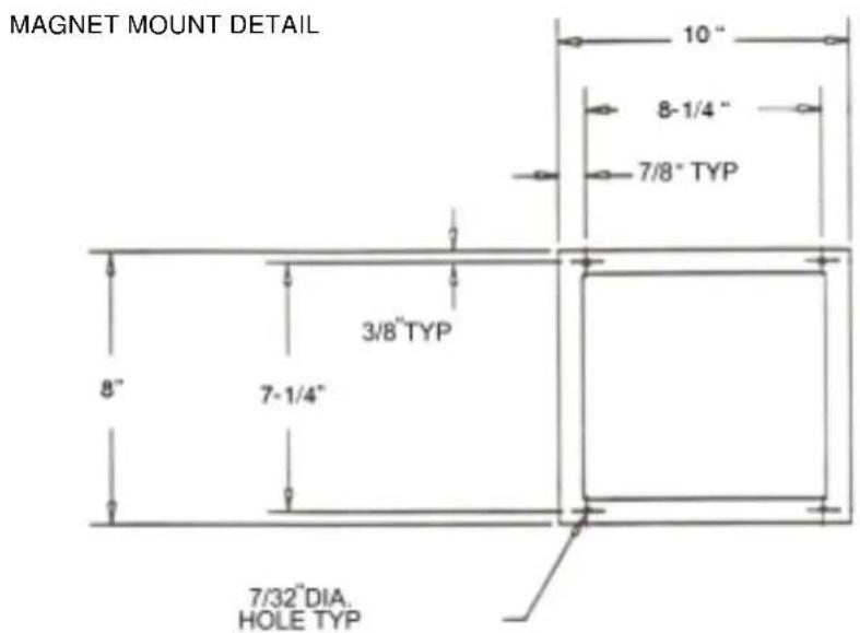
Fig. 4
TROUGH PIPING DETAIL (TROUGH EQUIPPED UNITS ONLY)
Install piping from the return water outlet on the end of the pulper motor housing to the trough flush nozzle as shown, (Fig. 5).

Fig. 5
FLANGE DETAIL

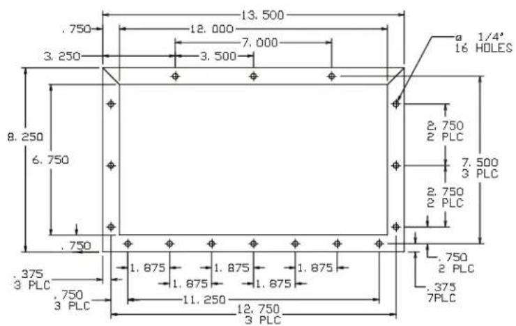
Fig. 6
PULPER INSTALLED UNDER A DISH TABLE
1) Cut a 20 1/8 " diameter hole in the top of the table as shown in the installation drawing.
2) Center the transition ring, provided, beneath the opening and weld it into place as shown.
3) Move the pulper into position under the 20 1/8 " diameter hole.
4) Install the trough gasket, provided, between the pulper's inlet and the trough outlet. Match and drill the pulper trough flange to the hole pattern in the table's flange and secure with the hardware provided.

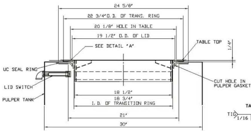
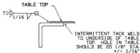
THE UC GASKET IS HELD TO THE UNDERSIDE OF THE PULPER TOP BY THE TWO HALVES OF THE TOP SEAL RING AND WELD STUDS. ELEVATE THE PULPER UNTIL THE GASKET IS IN CONTACT WITH THE BOTTOM EDGE OF THE UC TRANSITION RING. FROM THE INSIDE OF THE PULPER, CUT A HOLE IN THE GASKET USING THE TRANSITION RING AS A GUIDE (ROUGHLY 18 3/4 DIA.) ELEVATE THE PULPER THE REMAINDER OF THE WAY SINKING THE TRANSITION RING INTO THE HOLE IN THE GASKET.
DETAIL 'A'
TRANSITION RING
ATTACHMENT TO TABLE
BY APPLICABLE CONTRACTOR
Fig. 7
PLUMBING CONNECTIONS
WARNING: PLUMBING CONNECTIONS MUST COMPLY WITH APPLICABLE SANITARY, SAFETY AND PLUMBING CODES.
1) Piping for fresh water lines and drain lines are not provided by Hobart.
2) Pipe sizes are to be in accordance with Hobart recommendations.
3) All fittings must be pressure rated drainage type.
4) Keep drains accessible to machine. Do not install drains directly under Hobart equipment.
5) Do not put any external strain on the Hobart equipment.
6) Protect all Hobart equipment and piping from freezing and condensation.
Water Connection
Connect the cold water supply to the 1/2 " NPT internal-thread connector to the labeled port between the pulper and the waterpress with a manual shut-off valve. Incoming water pressure must be between 25 psig and 45 psig flowing.
Connect the hot water supply to the 1/2 " NPT internal-thread connector to the labeled port between the pulper and the waterpress with a manual shut-off valve. Incoming water pressure must be between 25 psig and 45 psig flowing.
Drain Connection
Install 2" pipe from the pulper drain valve to a suitable floor drain per local code. Use an open connection to the floor drain. Do not make a direct plumbing connection. DO NOT REDUCE.
Waterpress Overflow Connection
Install 1 1/2 " pipe from waterpress overflow to a suitable floor drain per local code. Use an open connection to the floor drain. Do not make a direct plumbing connection. DO NOT REDUCE.
ELECTRICAL CONNECTIONS
WARNING: ELECTRICAL AND GROUNDING CONNECTIONS MUST COMPLY WITH APPLICABLE PORTIONS OF THE NATIONAL ELECTRICAL CODE AND/OR OTHER LOCAL ELECTRICAL CODES.
WARNING: DISCONNECT THE ELECTRICAL POWER TO THE MACHINE AND FOLLOW LOCKOUT / TAGOUT PROCEDURES.
Refer to the electrical diagram located inside the wall-mounted control box.
The wall-mounted control box must be located away from the pulper and waterpress. Mount the wall-mounted control box (NEMA 4) so that the bottom of the box is at least 42" above the finished floor. To facilitate field wiring, terminal blocks are provided in both the wall-mounted control box and the machine control box located on the waterpress. Conduit and wiring (by others) should be installed according to the electrical diagram and the information on pages 8 and 9.
The incoming electrical power supply should be connected to the wall-mounted control box after the interconnections are made between the wall-mounted control box and the machine control box; terminals in each box are the same. This includes the ground wire.
Remote Push-Button Station (Standard)
One or more remote pushbutton station(s) with Start and Stop switches and the Timed Stop switch may be provided as ordered. These should be installed in a suitable and convenient location per local codes and the electrical diagram. Install the remote push-button station(s) on the dish table or at another convenient location (Fig. 8).
Motor Rotation
The Pulper motor, the Waterpress motor, and the Return Pump motor must be checked for correct rotation after the machine has filled. Arrows are provided to indicate the correct directions of motor rotation.
To check motor rotation, turn power on. Start and Stop the machine. Observe direction of motors.
If incorrect direction of rotation is observed, DISCONNECT ELECTRICAL POWER SUPPLY. Interchange two power supply leads to the motor connection terminal block, in the prewired machine control box. The overloads may need to be reset. Close the electrical access panels. Reconnect electrical power. Turn the machine on momentarily to verify correct motor rotation.
Electrical Installation
Refer to the wiring diagram shipped with the machine in the Remote Control Box.
1) Prewired control panels, operator devices and electric valves are furnished by Hobart.
2) Install 1 1/4 " watertight conduit from the wall-mounted control box to the prewired machine control box, pull motor wires and control wires through this conduit and make the final connections.
3) Ground all electrical equipment. Transformer produces a 115 VAC nominal control circuit voltage. The PLC produces 24 VDC circuit voltage.
4) Remote push-button station(s) to be mounted and wired at workstation by others. Bracket(s) for mounting push-button station(s) to be supplied by others.
5) Each push-button station houses two (2) illuminated push buttons plus a Timed Stop switch.
6) Control logic wiring shall be 18 AWG (THW) or equivalent for distances less than 120 feet.
OPERATION
WARNING: ROTATING PARTS INSIDE. KEEP HANDS OUT. DO NOT OPERATE WITHOUT: 1. ELECTRICAL INTERLOCK ON PULPER COVER AND / OR 2. ELECTRICAL INTERLOCK ON WATERPRESS DISCHARGE CHUTE. COVER MUST BE CLOSED AND THE DISCHARGE CHUTE MUST BE IN PLACE BEFORE UNIT WILL OPERATE.
WARNING: DISCONNECT ELECTRICAL POWER TO THE MACHINE AND FOLLOW LOCKOUT / TAGOUT PROCEDURES BEFORE CLEANING OR SERVICING.
CONTROLS
WALL-MOUNTED CONTROL BOX REMOTE PUSH-BUTTON STATION


Fig. 8
To start the system, make sure the main power switch on the wall-mounted control box is in the ON position.
- The hinged cover or undercounter cover plate must be closed (when equipped). Ensure the waterpress access cover is installed and the waterpress discharge chute cover is lowered.
- Push the START button. The machine begins to fill with water. During the initial fill, the green start button light will flash. When the machine has filled to the proper level, the green start button light will illuminate solid.
- Press the START button and wait until there is a continuous flow of water in the trough and/or feed tray (flush valves must be open and adjusted for proper throttling level if so equipped).
- Begin feeding waste into the trough and/or feed tray.
- To stop operation, press the STOP button.
FEEDING INSTRUCTIONS
Applications will vary widely; however, the following conditions could occur and should be monitored.
- Overfeeding. The waste system is designed for continuous uniform feeding. The feed rate should not exceed 60 pounds in a three minute period. Overfeeding reduces the machine's rated operating capacity. DO NOT OVERFEED.
If waste material is delivered in large plastic bags, tear open the bag and feed one at a time. Unopened bags can fill with air and float, hampering machine operation.
-
Foaming is caused by contaminants in the water or by certain materials in the waste, such as glue in corrugated cardboard. Chemical defoaming agent can be added to reduce this condition; consult your chemical supplier.
-
Corrosion. If the water and/or waste is running in an acidic or alkaline condition, use of a buffering agent is recommended to neutralize the water. Regular testing is recommended since rapid corrosion due to acidic or alkaline conditions can result in costly repairs.
-
Freezing. Protect all equipment and piping from freezing. Insulation and heating cables should be used where equipment or piping is exposed.
-
Non-Pulpables (items that cannot be made into pulp). The WPS1260 Pulper is designed to handle a limited amount of non-pulpable materials. Lighter non-pulpable items are eventually cut and processed with the pulp; heavier materials settle to the bottom of the tank.
-
DO NOT FEED glass or metal containers; if present in the plastic bags, sort them out. Glass and metal containers are highly abrasive and accelerate machine wear. It is better to recycle glass or metal containers using a can or bottle crusher to reduce the volume.
- DO NOT FEED rags, mop heads, wooden crates, oyster, or clam shells or heavy uncooked bones to the pulper. The waste system cannot efficiently reduce the volume of these items.
Caution: Heavy masonry materials, tramp iron and other materials of this nature can damage the cutters and seriously impair the pulper's ability to handle material of any kind.
Occasionally the amount of non-pulpable materials in the pulper tank may become excessive because of their slower processing rate. When this happens, press the STOP button and disconnect the electrical power. After machine is stopped, scoop out the non-pulpable materials. Then re-start the machine in the normal way.
When shutting down for short periods, it is not necessary to run the pulper until all the waste has been pumped out of the tank. Run pulper for a few minutes to thin down the slurry, and then shut off the machine.
During normal operation, there should be a strong flow of water returning to the pulper via trough and/or tray flush from the waterpress. This flow is a clue to the performance of the machine since a sharp reduction in this flow indicates the pulper is overloaded. If this occurs, stop feeding for a few minutes until return water resumes its normal flow.
Avoid slugging the machine with greasy swill or overloading the pulper with bread or pastry. Mix these items with bulky waste such as paper or corrugated boxes. The pulper will always perform better with clean water. It is good practice to drain the machine of dirty water after every meal period.
It is recommended that the discharge receptacle (garbage can) not be taller than the bottom of the discharge chute. Empty receptacle whenever necessary.
SHUTDOWN PROCEDURE
The following shutdown procedure must be followed before performing necessary cleaning and maintenance duties.
- With the pulper still running, push the Timed Stop switch to permit the system to be shut down automatically. The pulper will stop when the shutdown timer has timed out. Do not add additional waste when the unit is operating in the Timed Stop cycle. If additional material needs to be added after the Timed Stop cycle has started, push the Timed Stop switch at any time and return to normal feeding.
- Press the drain switch on the control panel to allow the unit to drain. Wait 30 seconds before proceeding to step 3.
- Turn off the electrical power by turning the main power switch on the remote control box to the OFF position.
CLEANING
Cleaning requires only a few minutes daily, but must be done on a regular basis and proper facilities must be available. NOTE: If daily cleaning schedules are not followed, the machine will become unsightly and odors will develop and machine performance may decrease. A hose with a good quality, lever-operated nozzle should be available, preferably with hot water, for clean-up of both the machine and the surrounding area.
Cleaning Instructions
Shut down the machine per Shutdown Procedure above.
WARNING: DISCONNECT ELECTRIC POWER SUPPLY AT MAIN CONTROL BOX; PLACE A TAG AT THE DISCONNECT SWITCH INDICATING THAT YOU ARE WORKING ON THE CIRCUIT; AND WAIT FOR THE PULPER DISK TO COME TO A COMPLETE STOP BEFORE PERFORMING ANY CLEANING PROCEDURES.
- Clean the pulper tank of any non-pulpable material. Use care, glass or other sharp items may be present in the pulper.
- Wash the interior of the tank with a hose, suitable brush, detergent and deodorant or other cleaning solution. Be sure to clean the underside of the upper tank flange.
- Using a spray hose, wash down the waterpress screen and interior walls of the waterpress and pulper tank. A long-handled, nylon bristle brush is recommended. Avoid spraying the chemical pump and control box mounted on the waterpress.
- Wipe down the equipment exterior.
- It is not necessary to dig out the plug of pulp remaining at the top of the waterpress screw. After the machine has been cleaned, wash down the floor. Replace all removed parts. The system is now ready to be started.
Cleaning Compounds
Cleaning compounds used with the WPS1260 waste system should combine five important features: Detergency, disinfection, pH buffering, odor control and bio-degradability.
Consult your chemical supplier for recommendations.
MAINTENANCE
WARNING: DISCONNECT ELECTRICAL POWER TO THE MACHINE AND FOLLOW LOCKOUT / TAGOUT PROCEDURES BEFORE CLEANING OR SERVICING.
MOTORS
Motors should be kept free of dirt, and ventilation openings must not be restricted.
WATERPRESS DRIVE
The waterpress drive consists of a close coupled motor and speed reducer. The gears in the speed reducer run in an oil reservoir that must be checked every three months. With the machine stopped, remove the oil level plug. If the oil level is not high enough to drain out of the case, add a small quantity of Mobil Gear Oil #629 (Hobart Part Number: 103881-72) until it just starts to run out of the hole.
TROUBLESHOOTING
SYMPTOM POSSIBLE CAUSE POSSIBLE CORRECTIVE ACTION
| Machine will not start. 1. | Circuit breaker tripped at power supply. 1. Reset circuit breaker.2. Power handle on main control box is Off. 2. Turn handle to On position.3. Pulper cover not in proper position. 3. Put pulper cover in proper position.4. Discharge chute lid not in proper position. 4. Put discharge chute lid in proper position.5. No water or not enough water in machine. 5. See "No water or no water make-up."6. Overload is tripped. 6. Reset overload. | |
| No water or no water 1. W/ Water supply off. 1. Turn water supply on.make-up. 2. Drain valve open or leaking. 2. Close drain valve. Repair if leaking. | ||
| Pulper jammed. 1. Pulper | overloaded. 1. Turn machine off at main control panel.2. Pulping disc jammed with scrap metal or heavy material. | |
| Waterpress jammed. | 1. Discharge chute outlet obstructed.2. Hardened plug in waterpress.3. Trash container is full and pulp is backing up in discharge chute. | 1. Turn machine off at main control panel. Remove residual pulp.2. Remove hardened waste material.3. Empty trash container and remove loose pulp from discharge chute. |
| Will not drain or drains very slowly. | 1. Pulper full of unpulped material.2. Drain clogged. | 1. Run pulper until pulp has been processed. If it will not process the material, turn the machine off and clean out the pulper tank.2. Use water pressure to eliminate clog. |
| Excessive foaming in waterpress. | 1. Pulping of certain materials, such as glossy paper, cardboard, and potatoes will produce large quantities of foam.2. Excessive deodorizer or detergent. | 1. Add defoaming agent.2. Drain machine and refill with fresh water.3. Turn pulper off when not feeding machine. |
| Pulp coming out of waterpress is too wet. | 1. Screen clogged. | 1. Clean waterpress screen.2. Contact Hobart Service. |
SERVICE
Contact your local Hobart-authorized service office for any repairs or adjustments needed on this equipment.
- WPS1260 WASTEPRO TM
- WASTE EQUIPMENT SYSTEM
- HOBART
- TABLE OF CONTENTS
- GENERAL 3
- INSTALLATION 4
- OPERATION 10
- MAINTENANCE....13
- TROUBLESHOOTING 14
- INSTALLATION, OPERATION AND CARE OF WPS1260 WASTEPRO™ WASTE EQUIPMENT SYSTEM
- SAVE THESE INSTRUCTIONS GENERAL
- INSTALLATION
- UNPACKING
- LOCATION
- VIBRATION ISOLATION FOOTPADS AND LEVELING
- CHEMICAL FEEDER PUMP (STANDARD)
- THE FOLLOWING PARTS MAY BE INCLUDED (DEPENDING ON OPTIONS SELECTED)
- SILVER SAVER — BY OTHERS (TROUGH EQUIPPED UNITS ONLY)
- TROUGH GASKET (TROUGH EQUIPPED UNITS ONLY)
- OPTIONAL MAGNET FOR SILVER SAVER (TROUGH EQUIPPED UNITS ONLY)
- TROUGH PIPING DETAIL (TROUGH EQUIPPED UNITS ONLY)
- FLANGE DETAIL
- PULPER INSTALLED UNDER A DISH TABLE
- PLUMBING CONNECTIONS
- WATER CONNECTION
- DRAIN CONNECTION
- WATERPRESS OVERFLOW CONNECTION
- ELECTRICAL CONNECTIONS
- REMOTE PUSH-BUTTON STATION (STANDARD)
- MOTOR ROTATION
- ELECTRICAL INSTALLATION
- OPERATION
- CONTROLS
- FEEDING INSTRUCTIONS
- CAUTION: HEAVY MASONRY MATERIALS, TRAMP IRON AND OTHER MATERIALS OF THIS NATURE CAN DAMAGE THE CUTTERS AND SERIOUSLY IMPAIR THE PULPER'S ABILITY TO HANDLE MATERIAL OF ANY KIND
- SHUTDOWN PROCEDURE
- CLEANING
- CLEANING INSTRUCTIONS
- CLEANING COMPOUNDS
- MAINTENANCE
- MOTORS
- WATERPRESS DRIVE
- TROUBLESHOOTING
- SERVICE
Brand : Hobart
Model : WastePro WPS1260
Category : Waste Management Equipment