DSG3060-IQ - Oscilloscope Rigol - Free user manual and instructions
Find the device manual for free DSG3060-IQ Rigol in PDF.


| Product Type | RF Signal Generator |
| Brand | Rigol |
| Model | DSG3060-IQ |
| Frequency Range | 9 kHz to 6 GHz |
| Output Power Range | -130 dBm to +20 dBm |
| Modulation Types | AM, FM, PM, Pulse, IQ |
| Display | 4.3-inch TFT LCD with touchscreen |
| Connectivity | USB, LAN, GPIB (optional) |
| Dimensions (WxHxD) | 350 x 180 x 100 mm |
| Weight | 4.5 kg |
| Power Supply | 100-240 V AC, 50/60 Hz |
| Operating Temperature | 0°C to 50°C |
| Storage Temperature | -20°C to 70°C |
| Warranty | 3 years |
| Cleaning | Wipe with a dry, lint-free cloth |
| Safety | Complies with CE, UL, and CSA standards |
| Spare Parts | Contact Rigol service center for replacement parts |
| Repairability | Professional repair recommended; no user-serviceable parts inside |
Frequently Asked Questions - DSG3060-IQ Rigol
User questions about DSG3060-IQ Rigol
0 question about this device. Answer the ones you know or ask your own.
Ask a new question about this device
Download the instructions for your Oscilloscope in PDF format for free! Find your manual DSG3060-IQ - Rigol and take your electronic device back in hand. On this page are published all the documents necessary for the use of your device. DSG3060-IQ by Rigol.
USER MANUAL DSG3060-IQ Rigol
Guaranty and Declaration
Copyright
© 2013 RIGOL TECHNOLOGIES, INC. All Rights Reserved.
Trademark Information
RIGOL is a registered trademark of RIGOL TECHNOLOGIES, INC.
Publication Number
UGG01112-1112
Software Version
00.01.04
Software upgrade might change or add product features. Please acquire the latest version of the manual from RIGOL website or contact RIGOL to upgrade the software.
Notices
● RIGOL products are covered by P.R.C. and foreign patents, issued and pending.
- RIGOL reserves the right to modify or change parts of or all the specifications and pricing policies at company's sole decision.
● Information in this publication replaces all previously corresponding material.
● Information in this publication is subject to change without notice.
- RIGOL shall not be liable for either incidental or consequential losses in connection with the furnishing, use or performance of this manual as well as any information contained.
- Any part of this document is forbidden to be copied, photocopied or rearranged without prior written approval of RIGOL.
Product Certification
RIGOL guarantees this product conforms to the national and industrial standards in China as well as the ISO9001:2008 standard and the ISO14001:2004 standard. Other international standard conformance certification is in progress.
Contact Us
If you have any problem or requirement when using our products or this manual, please contact RIGOL.
E-mail: service@rigol.com
Website: www.rigol.com
Safety Requirement
General Safety Summary
Please review the following safety precautions carefully before putting the instrument into operation so as to avoid any personal injury or damage to the instrument and any product connected to it. To prevent potential hazards, please follow the instructions specified in this manual to use the instrument properly.
Use Proper Power Cord.
Only the exclusive power cord designed for the instrument and authorized for use within the local country could be used.
Ground the Instrument.
The instrument is grounded through the Protective Earth lead of the power cord. To avoid electric shock, connect the earth terminal of the power cord to the Protective Earth terminal before connecting any input or output terminals.
Connect the Probe Correctly.
If a probe is used, the probe ground lead must be connected to earth ground. Do not connect the ground lead to high voltage. Improper way of connection could result in dangerous voltages being present on the connectors, controls or other surfaces of the oscilloscope and probes, which will cause potential hazards for operators.
Observe All Terminal Ratings.
To avoid fire or shock hazard, observe all ratings and markers on the instrument and check your manual for more information about ratings before connecting the instrument.
Use Proper Overvoltage Protection.
Ensure that no overvoltage (such as that caused by a bolt of lightning) can reach the product. Otherwise, the operator might be exposed to the danger of an electric shock.
Do Not Operate Without Covers.
Do not operate the instrument with covers or panels removed.
Do Not Insert Objects Into the Air Outlet.
Do not insert objects into the air outlet, as doing so may cause damage to the instrument.
Use Proper Fuse.
Please use the specified fuses.
Avoid Circuit or Wire Exposure.
Do not touch exposed junctions and components when the unit is powered on.
Do Not Operate With Suspected Failures.
If you suspect that any damage may occur to the instrument, have it inspected by RIGOL authorized personnel before further operations. Any maintenance, adjustment or replacement especially to circuits or accessories must be performed by RIGOL authorized personnel.
Provide Adequate Ventilation.
Inadequate ventilation may cause an increase of temperature in the instrument, which would cause damage to the instrument. So please keep the instrument well ventilated and inspect the air outlet and the fan regularly.
Do Not Operate in Wet Conditions.
To avoid short circuit inside the instrument or electric shock, never operate the instrument in a humid environment.
Do Not Operate in an Explosive Atmosphere.
To avoid personal injuries or damage to the instrument, never operate the instrument in an explosive atmosphere.
Keep Instrument Surfaces Clean and Dry.
To avoid dust or moisture from affecting the performance of the instrument, keep the surfaces of the instrument clean and dry.
Prevent Electrostatic Impact.
Operate the instrument in an electrostatic discharge protective environment to avoid damage induced by static discharges. Always ground both the internal and external conductors of cables to release static before making connections.
Use the Battery Properly.
Do not expose the battery (if available) to high temperature or fire. Keep it out of the reach of children. Improper change of a battery (lithium battery) may cause an explosion. Use the RIGOL specified battery only.
Do Not Overload the Output.
In order to avoid damage to the instrument, the reverse DC voltage on the RF output connector cannot exceed 50 V; the reverse power must be less than +40 dBm (10 W) in the frequency range from 1 MHz to 6 GHz.
Handle with Caution.
Please handle with care during transportation to avoid damage to keys, knobs, interfaces, and other parts on the panels.
Safety Notices and Symbols
Safety Notices in this Manual:

WARNING
Indicates a potentially hazardous situation or practice which, if not avoided, will result in serious injury or death.

CAUTION
Indicates a potentially hazardous situation or practice which, if not avoided, could result in damage to the product or loss of important data.
Safety Terms on the Product:
DANGER
It calls attention to an operation, if not correctly performed, could result in injury or hazard immediately.
WARNING
It calls attention to an operation, if not correctly performed, could result in potential injury or hazard.
CAUTION
It calls attention to an operation, if not correctly performed, could result in damage to the product or other devices connected to the product.
Safety Symbols on the Product:
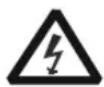
Hazardous Voltage

Safety Warning

Protective Earth Terminal
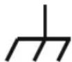
Chassis Ground
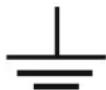
Test
Ground
Do not store or leave the instrument where it may be exposed to direct sunlight for long periods of time.
Cleaning
Clean the instrument regularly according to its operating conditions.
- Disconnect the instrument from all power sources.
- Clean the external surfaces of the instrument with a soft cloth dampened with mild detergent or water. When cleaning the LCD, take care to avoid scarifying it.

CAUTION
To avoid damage to the instrument, do not expose it to caustic liquids.

WARNING
To avoid short-circuit resulting from moisture or personal injuries, ensure that the instrument is completely dry before connecting it to the power supply.
Environmental Considerations
The following symbol indicates that this product complies with the WEEE Directive 2002/96/EC.
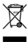
Product End-of-Life Handling
The equipment may contain substances that could be harmful to the environment or human health. In order to avoid the release of such substances into the environment and harm to human health, we encourage you to recycle this product in an appropriate system that will ensure that most of the materials are reused or recycled appropriately. Please contact your local authorities for disposal or recycling information.
From: RIGOL Technologies Inc
Date:May5,2014
156# Cai He Village, Sha He Town, Chang Ping District, Beijing, China
http://www.rigol.com
Declaration of RoHS&WEEE Conformity
RoHS: The European Union of 2011/65/EU Restriction of Hazardous Substances(RoHS) Directive, which applies to all electrical products and their component parts, offered for sale into the European Union after July 22, 2014, restricts the presence of the six substances: Lead(Pb), Cadmium(Cd), Mercury(Hg), Hexavalent Chromium( Cr^6+ ), Polybrominated biphenylethers(PBBs), and Polybrominated diphenylethers(PBDEs), In view of legal and market requirements, Rigol has restricted use of Pb,Cd, Hg, Cr^6+ , PBBs, PBDEs in our products. In addition, we require all our direct suppliers to strictly limit or prohibit use of hazardous substances. All its AVL(Approved Vendors List) components apply for RoHS.
Content of Compliance
| Lead | <0.1% by weight (1000 ppm) | Mercury | <0.1% by weight (1000 ppm) |
| Cadmium | <0.01% by weight (100 ppm) | Hexavalent Chrome( Cr^2+ ) | <0.1% by weight (1000 ppm) |
| PBBs | <0.1% by weight (1000 ppm) | PBDEs | <0.1% by weight (1000 ppm) |
WEEE: The European Union of 2012/19/EU, Waste Electrical and Electronic Equipment percentage of reused, recycled and recovered materials, such as metals · plastics, and components of waste electrical and electronic equipment.
We are registered in Germany in the WEEE(in Germany, EAR) register as a manufacturer of category 9(monitoring and control)equipment and have the assigned registration number
WEEE-Reg.-No.: DE88132002
in our commercial documents.
RIGOL Technologies Ind
Weiming Mao
Director of Central Quality and
Environmental Management
DSG3000 Series Overview
The DSG3000 series is a high-performance RF signal generator. It provides comprehensive modulation solutions such as: pulse modulation with customizable pulse train and I/Q modulation (optional), and standard AM/FM/ M analog modulation. All modulation schemes support internal and external modulation sources. In addition, to meet the demands of production environments, the DSG3000 is designed to be both highly stable and reliable. The DSG3000 series also features a clear user interface, small size and light weight. It is easy to operate and can output stable, precise and pure signals. It is an ideal tool for various fields such as communication, computers, instrumentation, R&D, education, production and maintenance.
Main Features:
● The highest frequency: 3 GHz/6 GHz
● Amplitude accuracy: <0.5dB (typical)
● Output amplitude range: -130 dBm to +13 dBm
● High signal purity, phase noise: <-110dBc/Hz@20kHz (typical)
- Standard 0.5ppm internal clock; 5ppb high stable clock for option
- Standard AM/FM/ M analog modulation
- Standard pulse modulation; on/off ratio up to 80dB; pulse train generator (optional)
● I/Q modulation and I/Q baseband output
● All modulation schemes support internal and external modulation modes
● Standard 2U height design to save rack space. Rack mount kit is available
- Standard USB/LAN/GPIB remote control interfaces. SCPI command set for remote control
● Wear-free electronic attenuator design
- Well-designed automatic flatness calibration function (Cables, attenuators, amplifiers and so on) for test systems with power meter control
Document Overview
Main contents in this manual
Chapter 1 Quick Start
This chapter introduces the front panel, rear panel and user interface of the RF signal generator as well as the precautions when using the instrument for the first time.
Chapter 2 Front Panel Operations
This chapter describes the front panel function keys of the RF signal generator and introduces the menu functions under each key in details.
Chapter 3 Remote Control
This chapter introduces the remote control method of RF signal generator.
Chapter 4 Application Examples
This chapter describes intuitively RF signal generator with operation examples.
Chapter 5 Troubleshooting
This chapter lists commonly encountered failures that may appear during the use of the RF signal generator and their solutions.
Chapter 6 Specifications
This chapter lists the performances and general specifications of the instrument.
Chapter 7 Appendix
This chapter provides the information about the options and accessories, as well as other points for attention.
Format Conventions in this Manual
1. Button:
The key at the front panel is denoted by the following format: "Text Box + Button Name (Bold)" in the manual, for example, FREQ denotes the FREQ key.
2. Menu:
The menu is denoted by the following format: "Character Shading + Menu Word (Bold)" in the manual, for example, Frequency denotes the frequency item under FREQ.
3. Connector:
The connector at the front or rear panel is denoted by the following format: "Square Brackets + Connector Name (Bold)" in the manual, for example, [RF OUTPUT 50Ω].
4. Operation Steps:
The next step of the operation is denoted by an arrow “→” in the manual. For example, Frequency denotes pressing on the front panel and then pressing Frequency.
Content Conventions in this Manual
The DSG3000 series RF signal generator includes the modes DSG3030 and DSG3060. The illustrations in this manual are based on DSG3060.
| Model | Frequency Range |
| DSG3030 | 9kHz ~ 3GHz |
| DSG3060 | 9kHz ~ 6GHz |
Manuals of this Product
The manuals of this product include the quick guide, user's guide, programming guide and data sheet. The latest versions of the manuals can be downloaded from www.rigol.com.
Contents
Guaranty and Declaration....I
Safety Requirement ...... II
General Safety Summary......II
Safety Notices and Symbols......IV
Care and Cleaning......VIII
Environmental Considerations......VIII
DSG3000 Series Overview....X
Document Overview.... XI
Chapter 1 Quick Start....1-1
General Inspection 1-2
Appearance and Dimensions.... 1-3
Front Panel Overview.... 1-5
Rear Panel Overview....1-12
To Use DSG3000 for the First Time....1-17
To Connect the Power Supply....1-17
Power-on Inspection 1-18
To Set the System Language....1-18
To Replace the Fuse 1-19
User Interface....1-20
Normal Display Mode 1-20
Parameter Zoom-in Mode....1-23
To Use the Built-in Help System 1-24
Chapter 2 Front Panel Operations ......2-1
To Set the Frequency Parameters.... 2-2
Frequency 2-2
Frequency Offset 2-2
Phase Offset.... 2-3
To Set the Amplitude Parameters 2-4
Amplitude 2-4
Amplitude Limit 2-4
Amplitude Offset 2-5
Attenuation Mode 2-6
Attenuation 2-6
ALC 2-7
Hold Mode 2-7
Flatness Calibration.... 2-8
Amplitude Unit....2-10
Sweep....2-10
Sweep Manner 2-10
Sweep Direction 2-11
Sweep Type 2-11
Sweep Mode 2-16
Single Sweep 2-17
Reset Sweep 2-17
Trigger Mode....2-17
Modulation 2-20
Amplitude Modulation (AM) 2-20
Frequency Modulation (FM) 2-23
Phase Modulation (ΦM) 2-25
Pulse Modulation 2-27
I/Q Modulation (Option IQ-DSG3000) 2-35
LF Output 2-40
To Enable the LF Output....2-40
To Set the LF Parameters 2-40
Power Meter (Option PMC-DSG3000) 2-45
To Enable the Power Meter 2-45
Zero Type 2-46
Zero 2-46
Frequency Mode 2-46
Frequency....2-46
Average Measurement 2-47
Preset....2-47
Limit Measurement 2-47
Recorder....2-49
Relative Measurement....2-50
Statistics....2-50
Unit 2-51
System Information 2-51
RX1000 (Option) 2-52
Store and Recall....2-53
File Type....2-53
Save....2-55
Recall 2-58
Rename 2-58
Delete 2-59
Copy 2-59
To Create a Directory 2-59
Filename Prefix 2-60
Disk Management 2-60
System Update....2-60
To Set the System Parameters 2-61
Language 2-61
Reset....2-61
I/O Configuration 2-62
Display Setting 2-64
Power Status....2-64
Information....2-65
License 2-65
Self-test 2-66
Sanitation 2-67
Chapter 3 Remote Control....3-1
Remote Control Overview 3-2
Control Via USB.... 3-3
Control Via LAN 3-5
Control Via GPIB 3-8
Chapter 4 Application Examples....4-1
To Output RF Signal 4-2
To Output RF Sweep Signal 4-3
To Output RF Modulated Signal 4-5
Pulse Train Application 4-6
Chapter 5 Troubleshooting....5-1
Chapter 6 Specifications....6-1
Specifications.... 6-2
Frequency 6-2
Level 6-4
Internal Modulation Generator (LF) 6-5
Modulation ^[1] 6-6
Input and Output....6-10
General Specifications....6-11
Chapter 7 Appendix....7-1
Appendix A: DSG3000 Accessories and options.... 7-1
Appendix B: Warranty 7-2
Index 1
Chapter 1 Quick Start
This chapter guides users to quickly get familiar with the appearance, dimensions, front panel, rear panel, and the user interface of DSG3000 series RF signal generator.
The contents of this chapter are as follows:
■ General Inspection
■ Appearance and Dimensions
■ Front Panel Overview
■ Rear Panel Overview
■ To Use DSG3000 for the First Time
■ To Replace the Fuse
■ User Interface
■ To Use the Built-in Help System
General Inspection
1. Inspect the packaging
If the packaging has been damaged, do not dispose the damaged packaging or cushioning materials until the shipment has been checked for completeness and has passed both electrical and mechanical tests.
The consigner or carrier shall be liable for the damage to the instrument resulting from shipment. RIGOL would not be responsible for free maintenance/rework or replacement of the instrument.
2. Inspect the instrument
In case of any mechanical damage, missing parts, or failure in passing the electrical and mechanical tests, contact your RIGOL sales representative.
3. Check the accessories
Please check the accessories according to the packing lists. If the accessories are damaged or incomplete, please contact your RIGOL sales representative.
Appearance and Dimensions
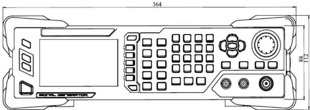
Figure 1-1 Front View (unit: mm)
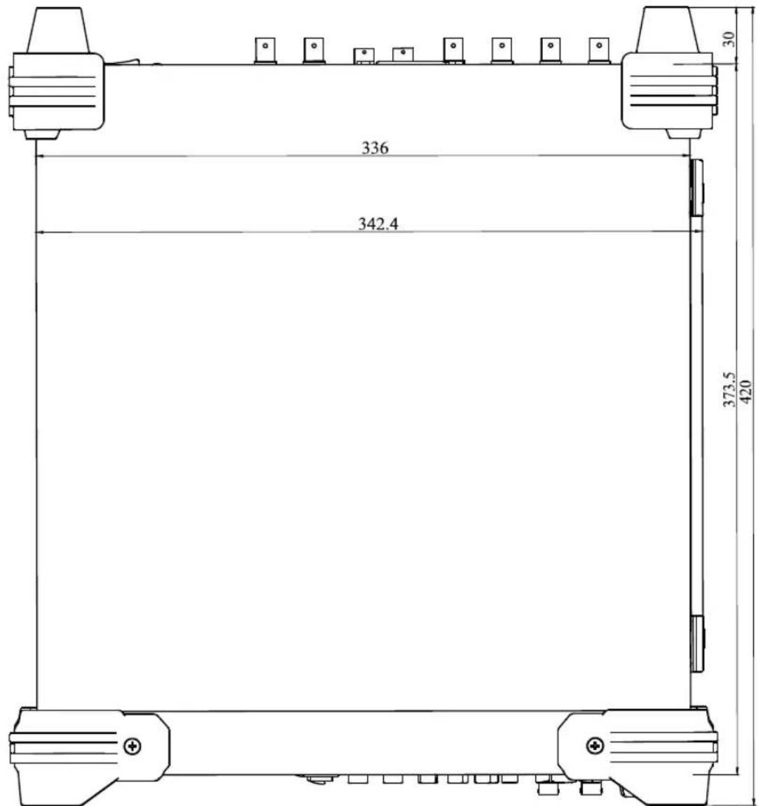
Figure 1-2 Top View (unit: mm)
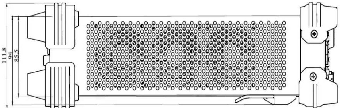
Figure 1-3 Lateral View (unit: mm)
Front Panel Overview
The front panel of DSG3000 series RF signal generator is as shown in the figure below. Click the number in the figure to view the corresponding introduction.
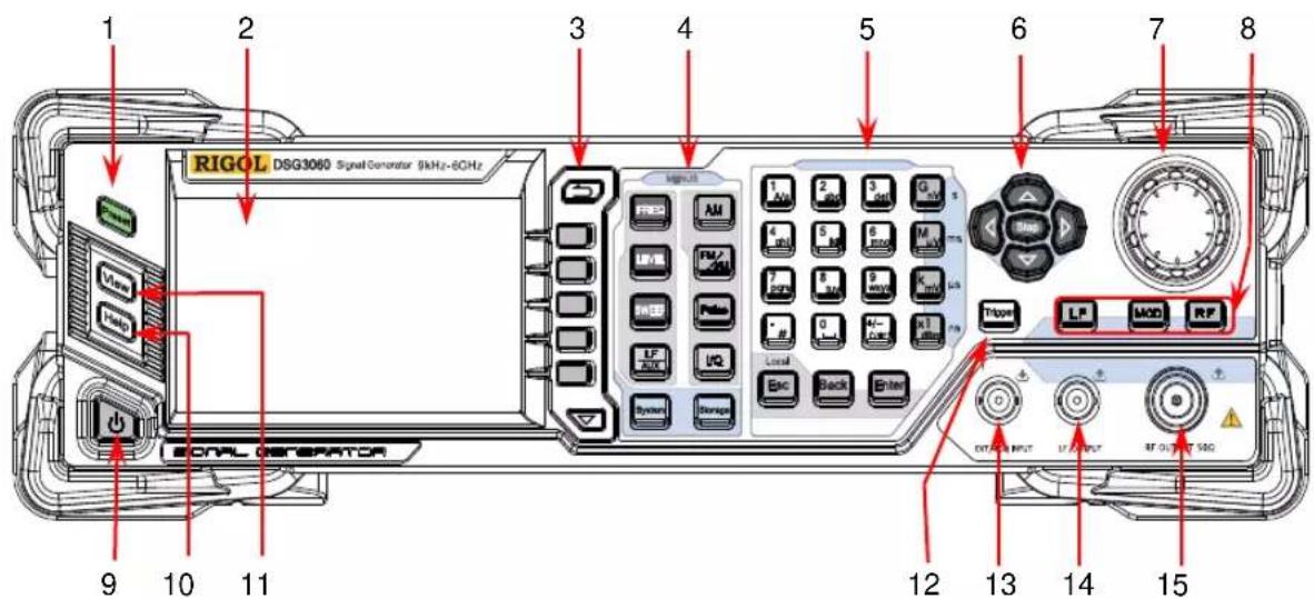
Figure 1-4 Front Panel
1. Restore to Preset Key
Restore the instrument to the preset state (factory state or user-stored state). For detailed information, refer to "Reset".
2. LCD Display
4.3 inch TFT high-resolution (480×272) color LCD display. The current settings and state of the instrument can be clearly displayed. For detailed information, refer to "User Interface".
3. Menu Control Keys
Quit the current menu and return to the previous menu.
Menu softkey. Corresponds to the menu label at the left of the softkey on the display. Press the softkey to activate the corresponding menu.
Menu page up/down key.
4. Function Keys
Set the frequency, frequency offset and phase offset of the RF output signal. For details, refer to "To Set the Frequency Parameters".
Set the amplitude and attenuation of the RF output signal and provide the flatness calibration function. For details, refer to "To Set the Amplitude Parameters".
Set the sweep type, sweep manner and sweep mode. For details, refer to "Sweep".
Set the parameters relating to amplitude modulation (AM). For details, refer to "Amplitude Modulation (AM)".
Set the parameters relating to frequency modulation (FM) and phase modulation ( M ). For details, refer to “Frequency Modulation (FM)” and “Phase Modulation ( M )”.
Set the parameters relating to pulse modulation and pulse generator. For details, refer to "Pulse Modulation".
Set the parameters relating to I/Q modulation and I/Q modulation source.
Set the parameters relating to LF output and other extended functions.
Store and recall the instrument state, flatness calibration data, sweep list and so on. For details, refer to “Store and Recall”.
Set the system-related parameters. For details, refer to "To Set the System Parameters".
5. Numeric Keyboard
The numeric keyboard supports Chinese characters, English uppercase /lowercase characters, numbers and commonly used symbols (include the decimal point, # , space and positive/negative sign+/-). It is mainly used to edit the file or folder name or set parameters.
The multiplexing key of number and letter is used to directly input the desired number or letter.
Used to switch among Chinese, English and number input modes.
When setting parameters, the input mode is fixed at number and this key is used to input the sign (“+” or “-”) of the value.
In number input mode, press this key to input 1.
In English input mode, press this key to switch between uppercase and lowercase letter input.
The multiplexing key of 0 and space:
In number input mode, press this key to input 0.
In Chinese or English input mode, press this key to input a space.
In number input mode, press this key to insert a decimal point at the current cursor.
In English input mode, press this key to input “#”.
In Chinese input mode, this key is invalid.
Used to set the unit of the parameter.
When setting a parameter, after using the numeric keyboard to input the numbers, press one of these keys to select the corresponding unit. The unit selected is related to the type of the parameter to be set.
| Parameter | G_nV | M_ V | k_mV | x1 | _dBm |
| Frequency | GHz | MHz | kHz | Hz | |
| Amplitude | nV | V | mV | dBm | |
| Period | s | ms | s | ns |
Local
When setting parameters, use this key to clear the number in the editing window and exit the parameter input state.
When editing filenames, use this key to clear the characters in the input bar.
During the keyboard test, use this key to exit the current test state.
When the instrument is in remote mode, use this key to return to local mode.
When setting parameters, use this key to delete the number at the left of the cursor.
When editing filenames, use this key to delete the character at the left of the cursor.
For the storage function, it is used to collapse the directory currently selected.
When setting parameters, use this key to finish the parameter input and add the default unit for the parameter.
When editing filenames, use this key to input the character currently selected by the cursor.
For the storage function, it is used to expand the directory currently selected.
6. Direction Keys/ Step Key
When setting the parameters, Step is used to set the step of the parameter currently selected.
The left/right direction keys are used to enter the parameter editing state and move the cursor to the specified digit.
The up/down direction keys are used to modify the value at the cursor or modify the parameter value at the current step.
For the storage function, the left/right direction keys are used to collapse or expand the directory currently selected.
The up/down direction keys are used to select the current directory or file.
When editing filenames, they are used to select the desired character.
7. Knob
natural_image
Circular mechanical component diagram with evenly spaced bolt holes (no text or symbols)When setting parameters, the knob is used to modify the value at the cursor or modify the parameter value at the current step.
When editing filenames, it is used to select the desired character.
For the storage function, it is used to select the current directory or file.
8. Output Control Keys
Used to turn on or off the LF output.
— Press this key, the backlight goes on and the LF label is displayed in the status bar in the user interface.
The LF output is turned on. At this point, the [LF OUTPUT] connector outputs the LF signal according to the current configuration.
— Press this key again, the backlight goes out and the LF output is turned off.
Used to turn on or off the RF output.
— Press this key, the backlight goes on and the RF label is displayed in the status bar in the user interface.
The RF output is turned on. At this point, the [RF OUTPUT 50Ω] connector outputs RF signal or RF sweep signal according to the current configuration.
— Press this key again, the backlight goes out and the RF output is turned off.
Used to turn on or off the RF modulation output.
— Press this key, the backlight goes on and the MOD label is displayed in the status bar in the user interface. The RF modulation output is turned on. At this point, the [RF OUTPUT 50Ω] connector outputs modulated RF signal according to the current configuration (the backlight of RF must go on).
— Press this key again, the backlight goes out and the RF modulation output is turned off.
9. Power Key
Turn on or off the signal generator. When this key is turned off, the signal generator is in standby state, indicated by a pulsing LED. To fully remove power from the instrument, flip the rear panel power switch off and remove the power cord. In addition, this key has a delayed switching function. The instrument can be turned on or off only when pressing this key and holding it down for a certain time. With this feature, you can avoid turning off the instrument because of accidentally touching the key.
Press System → Power Status to select "Open" or "Default". When "Default" is selected, after the instrument is powered on and the power switch at the rear panel is turned on, you need to press this key to start the instrument. When "Open" is selected, the instrument will start automatically after it is powered on and the power switch at the rear panel is turned on.
10. Built-in Help System

To get the help information of any front panel key or menu softkey, press this key and then press the desired key.
11. View Switch Key

It is used to switch the interface display mode to normal mode or parameter zoom-in mode. For details, please refer to "User Interface".
12. Trigger Control Key
When the trigger type of SWEEP is "Key", press this key once to trigger a sweep.
When the trigger mode of Pulse is "Key", press this key once to enable a pulse modulation.
13. External Modulation Input Connector
When the modulation source of AM, FM and M is external, this connector is used to input the external modulating signal.
EXT MOD INPUT
14. LF Output Connector
When the backlight of LF goes on, this connector is used to output LF signal.
LF OUTPUT
15. RF Output Connector
natural_image
Three abstract symbols: concentric circles with an upward arrow, a warning triangle with an exclamation mark (no text or labels)When the backlight of RF goes on, this connector is used to output RF signal and RF sweep signal. When the backlights of RF and MOD go on, this connector is used to output RF modulated signal.
RF OUTPUT 50Ω

CAUTION
To avoid damage to the instrument, the reverse DC voltage on the RF output connector cannot exceed 50 V, the reverse power must be less than +40 dBm (10W) in frequency range from 1 MHz to 6 GHz.
Rear Panel Overview
The rear panel of DSG3000 series RF signal generator is as shown in the figure below. Click the number in the figure to view the corresponding introduction.
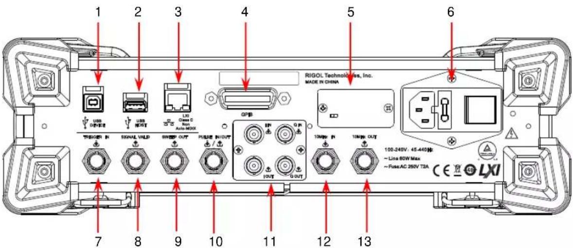
Figure 1-5 Rear Panel
1. USB Device

USB DEVICE
The instrument complies with USBTMC class protocol.
This interface is used to connect to a PC for remote instrument control.
2. USB Host

USB HOST
This input is used to connect the USB storage device to update the system, store system states and sweep lists. You can also connect the USB power sensor or power meter with USB interface to achieve power measurement control and amplitude calibration of a measurement system.
3. LAN
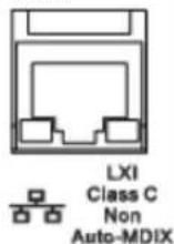
The instrument complies with LXI Core 2011 Device standard, and supports WebServer, Socket and other remote control modes.
This interface is used to connect the PC or network for remote instrument control.
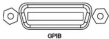
4. GPI B
natural_image
Pure electrical connector diagram without any text or symbolsThe instrument complies with the IEEE488.2 standard.
This interface is used to connect the PC to enable remote instrument control.
5. OCXO (option OCXO-A08)
natural_image
Pure electrical circuit lines without any symbolsOCXO is an oven controlled crystal oscillator. It is a frequency reference source with higher temperature stability.
NOTE: Forty minutes of warm-up is required for the OCXO to reach its rated frequency.
For ordering information of this option, please refer to the data sheet.
6. Power Input Connector, Fuse and Switch
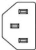
Power input connector.
The AC power supply specification of this signal generator is 100-240 V, 45-440 Hz. The power consumption of the instrument cannot exceed 60 W. When the signal generator is connected to AC power supply via this connector, the instrument selects the correct voltage range automatically and users do not need to select the voltage range manually.
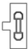
Fuse.
The fuse specification of this signal generator is AC 250 V, T2A.
If the fuse needs to be replaced, please refer to "To Replace the Fuse".
Power Switch
It is used to turn on or off the signal generator.
7. External Trigger Input Connector
TRIGGER IN
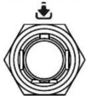
When the trigger type of SWEEP or "Swp-Sine" of LF output is "Ext", this connector is used to input the external trigger signal. You can set the polarity of trigger signal by pressing Trig Slope to select "Pos" or "Neg"
8. Signal Valid Output Connector
SIGNAL VALID
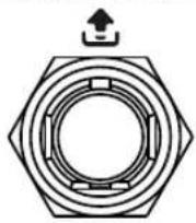
When the RF output frequency or amplitude is modified, after a certain response and processing time, the internal circuit of the instrument outputs RF signal with specified frequency and amplitude via the RF output connector at the front panel. During this process, the [SI GNAL VALID] connector outputs a pulse sync signal, indicating that the RF output signal is valid.
— High Level (+3.3 V): indicates that the RF signal is in configuration;
— Low Level (0 V): indicates that the RF signal is stable (namely, the signal is valid).
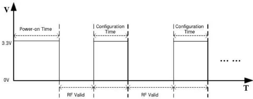
other
| Time Phase | Voltage (V) | | ------------------ | ----------- | | Power-on Time | 3.3 | | Configuration Time | 0 | | RF Valid | 0 | | Configuration Time | 3.3 | | ... | ... |9. Sweep Output Connector
SWEEP OUT
When the RF sweep function is enabled, the [SWEEP OUT] connector outputs a signal (0 V to +10 V) while the RF output connector at the front panel outputs the sweep signal according to the current setting. Each sweep corresponds to an output cycle.
— When the sweep type is step, this output signal is related to the choice of sweep shape which can be set to “Triangle” or “Ramp”.
— When the sweep type is list, the default of this output signal is ramp.
10. Pulse Signal Input/ Output Connector
PULSE IN/OUT
The function of this connector is determined by the current working mode of the pulse modulation.
PULSE IN:
— When the modulation source of Pulse is external, this connector is used to input the external pulse signal.
— When the modulation source of Pulse is internal and the trigger mode is "Ext Trig", this connector is used to input the external trigger signal.
— When the modulation source of Pulse is internal and the trigger mode is “Ext Gate”, this connector is used to input the external gated signal.
PULSE OUT:
When the modulation source of Pulse is internal and the switch of pulse output is "on", this connector is used to output the pulse signal of the internal generator. This output signal is related to the choice of pulse mode which can be set to "Single", "Double" or "Train".
11. I/ Q Modulating Signal In/ Out Connectors (option IQ-DSG3000)
When I/Q modulation type is “external”, it is used to input the I (In-Phase) baseband signal of I/Q modulation.
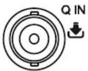
When I/Q modulation type is “external”, it is used to input the Q (Quadrature Phase) modulating signal of I/Q modulation.
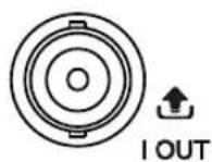
It is used to output the I (In-Phase) components of the I/Q modulation of the built-in baseband generator.
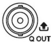
It is used to output the Q (Quadrature Phase) components of the I/Q modulation of the built-in baseband generator.
12. Reference Signal Input Connector
10MHz IN
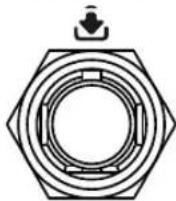
It is used to input the external 10 MHz reference clock signal which is used to synchronize the generator with other instruments. For more information about the external clock signal specification of this connector, please refer to the data sheet.
13. Reference Signal Output Connector
10MHz OUT
It is used to output the internal 10 MHz reference clock signal used to synchronize the generator with other instruments. For more information about the output clock signal specification of this connector, please refer to the data sheet.
To Use DSG3000 for the First Time
To Connect the Power Supply
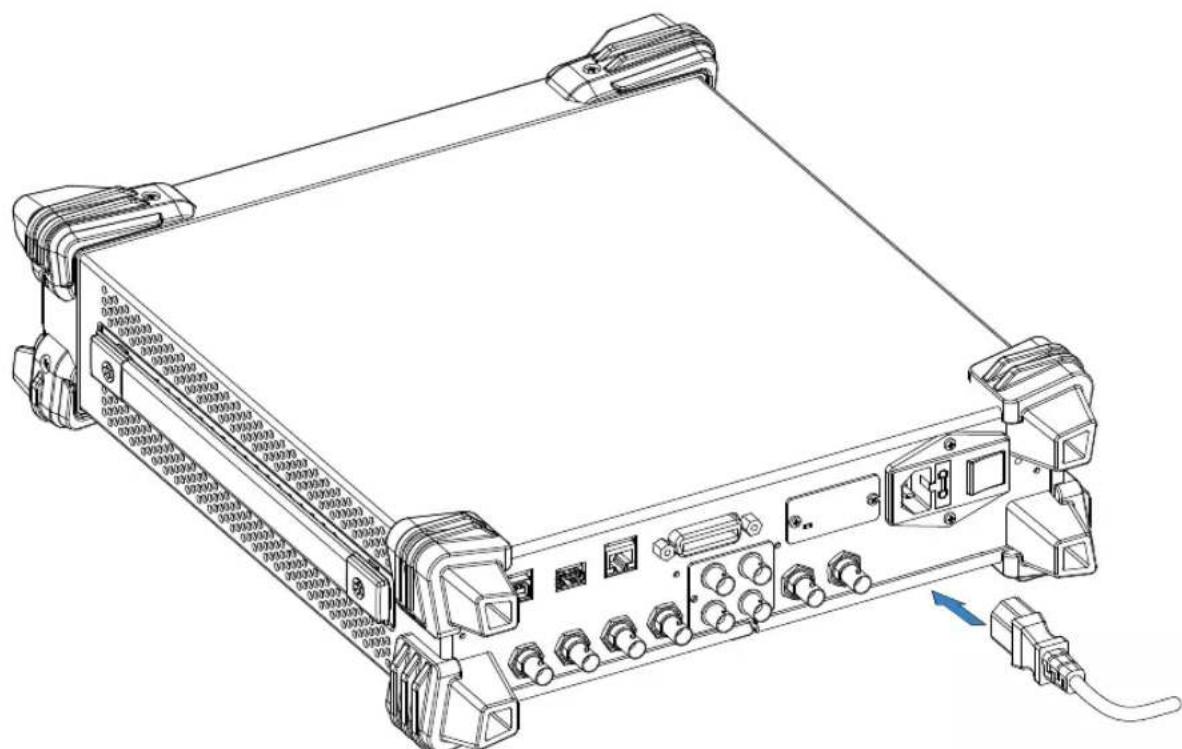
Please connect the signal generator to AC power supply using the power cord supplied in the accessories as shown in the figure below. The AC power supplies specification of this signal generator is 100-240 V, 45-440 Hz. The power consumption of the instrument cannot exceed 60 W. When the signal generator is connected to AC power supply via this connector, the instrument select the correct voltage range automatically and users do not need to select the voltage range manually.
natural_image
Technical line drawing of a mechanical device with ports, connectors, and a central panel (no text or symbols)Figure 1-6 To Connect the Power Supply

CAUTION
To avoid electric shock, use the standard power cable.
Power-on Inspection
After the power supply is correctly connected, press the power switch at the rear panel and the power key 📄 at the front panel to turn on the signal generator. During the start-up, the instrument performs initialization and self-test. After that, the instrument enters the default interface.
To Set the System Language
DSG3000 series RF signal generator supports multiple system languages. You can press System→Language to switch the system language.
To Replace the Fuse
To replace the fuse, please use the specified fuse and follow the steps below.
- Turn off the instrument, switch off the power supply and remove the power cord.
- Use a small straight screwdriver to pry out the fuse seat.
- Take out the fuse seat.
- Replace the old fuse with a specified fuse.
- Re-install the fuse seat.
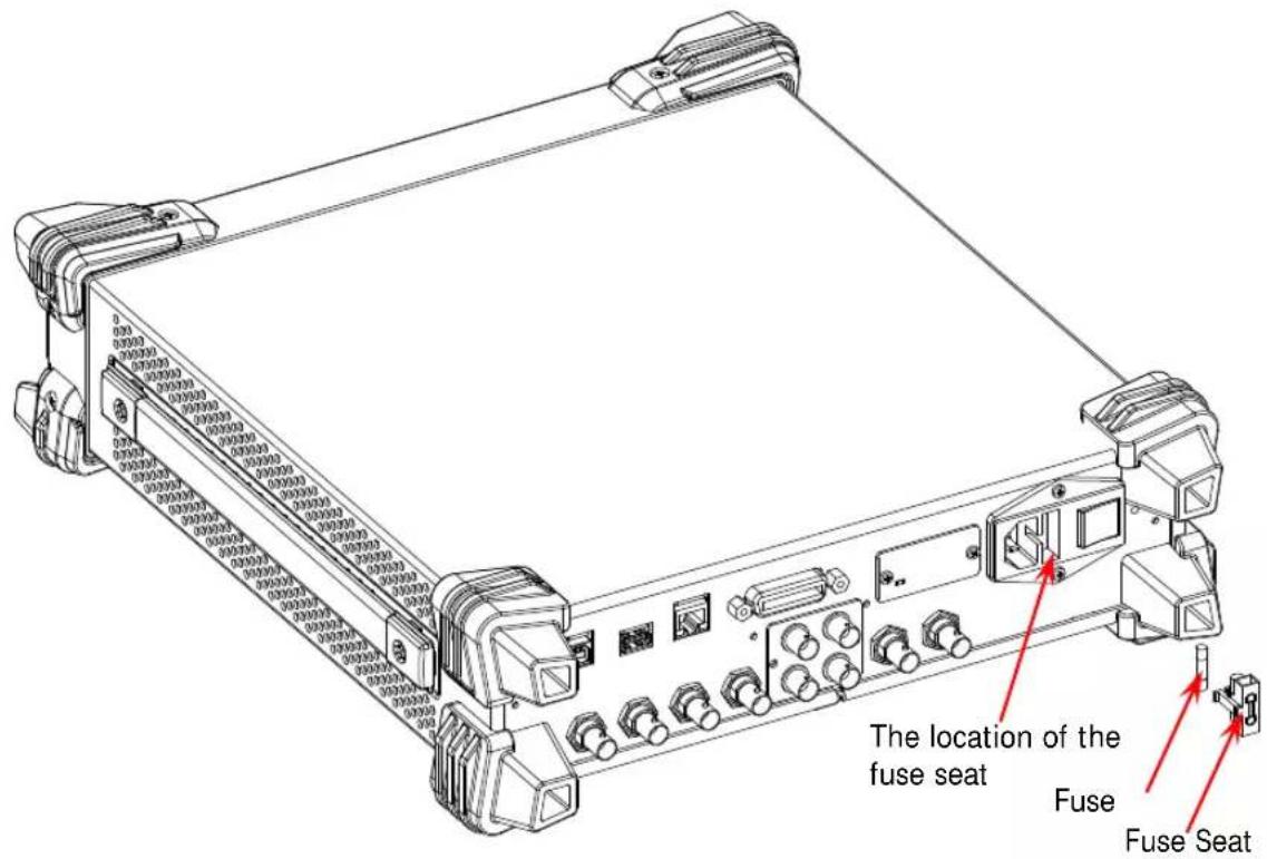
Figure 1-7 To Replace the Fuse

WARNING
To avoid electric shock, make sure that the instrument is turned off, the power supply is disconnected and the fuse used is up to standard before replacing the fuse.
User Interface
The user interface of DSG3000 series RF signal generator provides two display modes: normal display mode and parameter zoom-in mode. At power-on, the instrument enters the normal display mode by default. In this manual, the normal display mode of DSG3060 is taken as an example to illustrate the user interface of the instrument.
Normal Display Mode
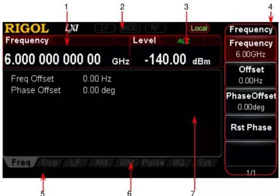
Figure 1-8 User Interface (Normal Display Mode)
1. Frequency Area
Display the current frequency setting of the RF signal generator.
— Offs : Displayed when the frequency offset is not 0 Hz.
— : Continuous sweep label. Displayed when the sweep type is "Freq" or "Freq&Lev" and the sweep mode is "Cont".
— : Single sweep label. Displayed when the sweep type is "Freq" or "Freq&Lev" and the sweep mode is "Single".
— : Forward sweep label. Displayed when the sweep type is "Freq" or "Freq&Lev" and the sweep direction is "Fwd".
— : Down sweep label. Displayed when the sweep type is "Freq" or "Freq&Lev" and the sweep direction is "Down".
— : Frequency sweep progress bar. Displayed when the sweep type is "Freq" or "Freq&Lev".
2. Status Bar
Indicate the states of some of the RF signal generator functions.
— LF : Displayed when the LF output is enabled. This is grayed out when the LF output is disabled.
— MOD : Displayed when the RF modulation output is enabled. This is grayed out when the RF modulation output is disabled.
— RF : Displayed when the RF output is enabled. This is grayed out when the RF output is disabled.
— Rmt : The RF signal generator is operating in remote control mode.
— Local : The RF signal generator is operating in local mode.
3. Amplitude Area
Display the current level setting of the RF signal generator.
— AH : Displayed when the attenuation mode is "Fixed".
— ALC : Displayed when the ALC state is "On".
— ALC : Displayed when the ALC state is "Auto".
— UF : Displayed when the flatness calibration switch is "On".
— Offs : Displayed when the amplitude offset is not 0 dB.
— : Continuous sweep label. Displayed when the sweep type is "Level" or "Freq&Lev" and the sweep mode is "Cont".
— : Single sweep label. Displayed when the sweep type is "Level" or "Freq&Lev" and the sweep mode is "Single".
— ↑ : Forward sweep label. Displayed when the sweep type is "Level" or "Freq&Lev" and the sweep direction is "Fwd".
— : Down sweep label. Displayed when the sweep type is “Level” or “Freq&Lev” and the sweep direction is “Down”.
— : Amplitude sweep progress bar. Displayed when the sweep type is “Level” or “Freq&Lev”.
4. Menu Display Area
The menus in this area correspond to the softkeys at the right of the screen. Pressing any softkey can enable the corresponding menu function.
5. Message Display Area
Display the operation error messages and prompt messages. You can press System → Information → System Msg to view the messages. When multiple messages are generated, you can use the up/down direction keys or knob to select the message row to be viewed. When the messages cannot be displayed completely in the list, press Verbose to view the complete information of the current row selected in the message list.
6. Function Status Area
Display the current active states of each function. Each function corresponds to at most four kinds of states as shown in the table below.
| Type | Explanation | Example |
| Gray text on a black background | The function is not selected and enabled. |  |
| Black text on a gray background | The function is selected and you can set the corresponding parameters. |  |
| White text on a gray background | The function is selected and enabled. |  |
| White text on a black background | The function is not selected but it is enabled. |  |
The status labels in the function status area as shown in the figure below.
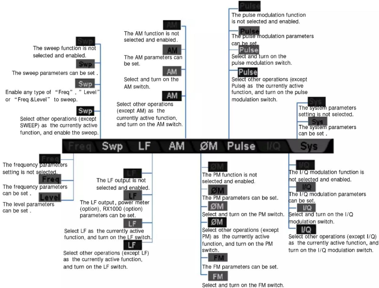
flowchart
graph TD
    A["The sweep function is not selected and enabled."] --> B["The AM function is not selected and enabled."]
    C["The sweep parameters can be set."] --> D["The AM parameters can be set."]
    E["Enable any type of “Freq”, “Level” or “Freq &Level” to sweep."] --> F["Select and turn on the AM switch."]
    G["Select other operations (except SWEEP) as the currently active function, and enable the sweep."] --> H["Select other operations (except AM) as the currently active function, and turn on the AM switch."]
    I["The level parameters can be set."] --> J["The LF output is not selected and enabled."]
    K["The frequency parameters setting is not selected."] --> L["The LF output, power meter (option), RX1000 (option) parameters can be set."]
    M["The frequency parameters can be set."] --> N["The LF output, power meter (option), RX1000 (option) parameters can be set."]
    O["The level parameters can be set."] --> P["Select LF as the currently active function, and turn on the LF switch."]
    Q["Select other operations (except LF) as the currently active function, and turn on the LF switch."] --> R["Select other operations (except LF) as the currently active function, and turn on the LF switch."]
    S["Pulse"] --> T["Pulse modulation function is not selected and enabled."]
    U["Pulse"] --> V["Pulse modulation parameters can be set."]
    W["Pulse"] --> X["Select and turn on the pulse modulation switch."]
    Y["Pulse"] --> Z["Select other operations (except Pulse) as the currently active function, and turn on the pulse modulation switch."]
    AA["The system parameters setting is not selected."] --> AB["The system parameters can be set."]
    AC["The I/Q modulation function is not selected and enabled."] --> AD["I/Q"]
    AE["The I/Q modulation parameters can be set."] --> AF["I/Q"]
    AG["Select and turn on the I/Q modulation switch."] --> AH["I/Q"]
    AI["Select other operations (except I/Q) as the currently active function, and turn on the I/Q modulation switch."] --> AJ["I/Q"]
    AK["The FM parameters can be set."] --> AL["FM parameters can be set."]
    AM["Select and turn on the FM switch."] --> AN["FM"]
Figure 1-9 Labels in Function Status Area
7. Text Display Area
Display the corresponding parameter information of the current function of the RF signal generator.
Parameter Zoom-in Mode
In normal display mode, pressing the display switch key View at the left of the screen can switch to the parameter zoom-in mode as shown in the figure below.
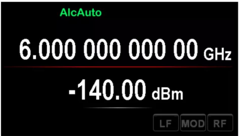
Figure 1-10 User Interface (Parameter Zoom-in Mode)
To Use the Built-in Help System
The DSG3000 built-in help system provides help information for all the function keys and menu softkeys located on the front panel. Users can view the help of any key when operating the instrument.
1. Acquire the built-in help
Press Help and the prompt message about how to acquire the help information is displayed in the test display area of the user interface, as shown in Figure 1-11. Then, press the desired key and the help information of that key is displayed in the text display area.
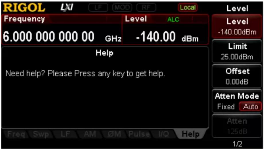
Figure 1-11 Help Interface
2. Page up/ down
When the help information is displayed on multiple pages, users can acquire the help information on the previous or next page using the direction keys or knob.
3. Turn off the current help information
When the help information is displayed in the text display area, pressing any key (except the direction keys and knob) at the front panel will turn off the help information currently displayed.
4. Acquire the help information of a menu softkey
Press Help and help information is displayed in the text display area. Then, press the desired menu softkey, the help information of the menu item corresponding to this menu softkey is displayed in the text display area.
5. Acquire the help information of any function key
Press Help and help information is displayed in the text display area. Then, press any function key and the function help information of this key is displayed in the text display area.
Chapter 2 Front Panel Operations
This chapter introduces each function key at the front panel as well as the menu functions under it in details.
The contents of this chapter are as follows:
■ To Set the Frequency Parameters
■ To Set the Amplitude Parameters
■ Sweep
■ Modulation
■ LF Output
■ Store and Recall
■ To Set the System Parameters
To Set the Frequency Parameters
Frequency
Set the RF output frequency.
Press FREQ → Frequency, use the numeric keyboard to input the value of the frequency and select the desired unit from the pop-up unit menu or unit keys.
● The frequency units available are GHz, MHz, kHz and Hz.
- Press Enter to select the current frequency unit by default.
- You can also press the left/right direction keys to enter the parameter editing state and move the cursor to the specified digit; and then use the up/down direction keys or knob to modify the value.
- After the frequency is set, you can use the up/down direction keys or knob to modify the frequency at the current step.
- Press FREQ → Frequency and then press Step to set the step.
Frequency Offset
Set the frequency offset relative to the RF output frequency.
When using an external mixer and other devices, you can set and read the frequency value through the external mixer on the RF source by setting the frequency offset.
Press FREQ → Offset, use the numeric keyboard to input the value of the frequency offset and select the desired unit from the pop-up unit menu or unit keys.
● The frequency offset units available are GHz, MHz, kHz and Hz.
- Press Enter to select the default unit (MHz).
- You can also press the left/right direction keys to enter the parameter editing state and move the cursor to the specified digit; and then use the up/down direction keys or knob to modify the value.
- You can also use the up/down direction keys or knob to modify the frequency offset at the current step.
- Press FREQ → Offset and then press Step to set the step.
Explanation
- When the frequency offset is 0 Hz, the frequency displayed in the interface (namely setting frequency) is equal to the actual output frequency.
- When frequency offset is not 0 Hz, the output frequency is determined by setting frequency and frequency offset. The three parameters satisfy the equation: setting frequency (display frequency) = output frequency + frequency offset
- The deviation (namely the actual output frequency) between interface display frequency and frequency offset cannot exceed the frequency range of instrument.
Phase Offset
Set the phase offset of the RF signal.
When multiple RF signal generators are used to output signals, you can adjust the phase offset of the instrument to synchronize the phase or set a fixed phase offset for the signals.
Press FREQ → Phase Offset, after that use the numeric keyboard to input the value of the phase offset and press deg or the unit key.
- Press Enter to select the default unit (deg).
- Press the left/right direction keys to enter the parameter editing state.
- You can also use the up/down direction keys or knob to modify the phase offset at the current step.
- Press FREQ → Phase Offset and then press Step to set the step.
- Press Rst Phase to reset the current phase offset to 0 deg.
To Set the Amplitude Parameters
Amplitude
Set the RF output amplitude.
Press LEVEL → Level, use the numeric keyboard to input the amplitude value and select the desired unit from the pop-up unit menu or unit keys.
● The amplitude units available are dBm, -dBm, mV, V and nV.
- Press Enter to select the default unit (dBm).
- You can also press the left/right direction keys to enter the parameter editing state and move the cursor to the specified digit and then use the up/down direction keys or knob to modify the value.
- You can also use the up/down direction keys or knob to modify the amplitude at the current step.
- Press LEVEL → Level and then press Step to set the step.
Amplitude Limit
Set the limit of the RF output amplitude. This value is the upper limit of the RF output amplitude.
To limit the output amplitude, you can use the amplitude limit function to avoid damage caused by delivering a high powered signal to the external circuit.
Press LEVEL → Limit, use the numeric keyboard to input the value of the amplitude limit and select the desired unit from the pop-up unit menu or unit keys.
● The amplitude limit units available are dBm, -dBm, mV, V and nV.
- Press Enter to select the default unit (dBm).
- You can also press the left/right direction keys to enter the parameter editing state and move the cursor to the specified digit; and then use the up/down direction keys or knob to modify the value.
- You can also use the up/down direction keys or knob to modify the amplitude limit at the current step.
- Press LEVEL → Limit and then press Step to set the step.
Amplitude Offset
Set the amplitude offset relative to the RF output amplitude.
If the external device or circuit has a fixed attenuation or gain, you can set and read the amplitude value after through the external device or circuit on the RF source by setting the amplitude offset.
Press LEVEL → Offset, use the numeric keyboard to input the amplitude offset value and press dB or the unit key.
● The amplitude offset unit available is dB.
- Press Enter to select the default unit (dB).
- You can also press the left/right direction keys to enter the parameter editing state and move the cursor to the specified digit and then use the up/down direction keys or knob to modify the value.
- You can also use the up/down direction keys or knob to modify the amplitude offset at the current step.
- Press LEVEL → Offset and then press Step to set the step.
Explanation
- When amplitude offset is 0 Hz, the amplitude displayed in the interface (namely setting amplitude) is equal to the actual output amplitude.
- When amplitude offset is not 0 Hz, output amplitude is determined by setting amplitude and amplitude offset. The three parameters satisfy the equation: setting amplitude (display amplitude) = output amplitude + amplitude offset
- The deviation (namely the actual output amplitude) between interface display amplitude and amplitude offset cannot exceed the amplitude range of instrument.
- The current amplitude range of instrument is determined by amplitude limit, attenuation mode, attenuation value and RF output frequency.
Attenuation Mode
Set the attenuation mode of RF output.
If you want to get a larger amplitude setting range, you can set the attenuation mode to auto. If you want to get higher amplitude accuracy in a smaller amplitude range, you can set the attenuation mode to fixed.
Press LEVEL → Atten Mode to set the attenuation mode of the RF output amplitude to "Auto" or "Fixed".
- Auto: the default mode. In this mode, the attenuator adjusts the attenuation automatically to match the current amplitude setting. Therefore, you can set the amplitude within the whole range.
- Fixed: in this mode, the attenuation is the value set in Atten. Therefore, you can only set the amplitude within a certain range. At this point, if the ALC is enabled, you can set the amplitude within a certain range continuously. Please refer to "Specifications". The AH label is displayed in the amplitude area in the user interface.
Explanation
When the attenuation mode of the RF output amplitude is auto, the internal attenuator provides attenuation for the output amplitude to get a larger dynamic output range.
Attenuation
Set the attenuation of the RF output amplitude in fixed attenuation mode.
Press LEVEL → Atten Mode to select "Fixed"; press Atten, use the numeric keyboard to input the amplitude attenuation value and press dB or the unit key.
● The amplitude attenuation unit available is dB.
- Press Enter to select the default unit (dB).
- You can also press the left/right direction keys to enter the parameter editing state and move the cursor to the specified digit and then use the up/down direction keys or knob to modify the value.
- You can also use the up/down direction keys or knob to modify the amplitude offset at the current step.
- Press Step to set the step.
ALC
Set the working state of the ALC function.
ALC is the automatic level control function. This function compares the actual output amplitude with the set amplitude and adjusts the output amplitude according to the comparison result to ensure the accuracy of the output amplitude.
Press LEVEL and use the menu page up/down key ▼ to open the 2/2 menu page. Press ALC to select "Off", "On" or "Auto".
● Off: turn off the ALC function.
- On: turn on the ALC function and the ALC label is displayed in the amplitude area in the user interface.
- Auto: turn on or off the function automatically according to the current state of the instrument and the ALC label is displayed in the amplitude area in the user interface.
Hold Mode
Set the hold mode of RF output amplitude.
When ALC is disabled, the instrument switches to "Sample & Hold" state. At this point, the RF signal generator samples and holds the amplitude setting values with ALC turned on. This allows the generator to maintain a constant output level.
Press LEVEL → S&H Mode to select "Manul" or "Auto".
- Manul: in this mode, the instrument performs a sample and hold operation each time S&H is pressed.
- Auto: the default mode. In this mode, the instrument performs a sample and hold operation each time the RF amplitude is set. In addition, you can also press S&H to perform an operation.
NOTE:
-
When IQ modulation is enabled and MOD is pressed (the backlight goes on), if no wavetable file is downloaded, the above menus are grayed out and disabled. In other situations, the menus are only valid when the ALC function is set to "Off".
-
When a sweep type is selected, if the step sweep time set is lower than 50 ms and the auto sample hold is enabled, "You can turn on the S&H when sweep time is greater than 50ms" will be displayed in the user interface.
Flatness Calibration
The flatness calibration function can adjust RF output amplitudes corresponding to the frequency points within the frequency range of the instrument to compensate for the external loss caused by cabling, switches or other devices. You can create the flatness calibration list and store the calibration list in internal or external memory. You can also recall the stored calibration list when required.
1. Set the flatness calibration state
Press LEVEL and use the page up/down key to open the 2/2 menu page; then, press Flatness → Switch to set the flatness calibration to "On" or "Off". When the flatness calibration is enabled, the UF label will be displayed in the amplitude area in the user interface.
2. Create the flatness calibration list
Press LEVEL → Flatness → Cal List to enter the editing interface of flatness calibration list.
| SN | Row number. You can use Insert and Delete to add and delete rows. |
| Freq | Frequency. The flatness calibration list can contain the amplitude calibration values of up to 6000 frequency points. The 6000 frequency points can locate in any frequency segment within the maximum frequency range available.You can save calibration lists applicable to different test settings or frequency ranges and recall different calibration list when required. |
| Level | Amplitude calibration value. When calibrating the amplitude of the current frequency point, only the actual output amplitude will be affected and the amplitude display value will not change. |
- Insert
Press Insert to insert a row with the same calibration value below the current row. At this point, the number of rows of the flatness calibration list increases by one.
- Delete
Press Delete to delete the calibration value of the row currently selected. At this point, the number of rows of the flatness calibration list reduces by one.
- Goto Row
Press Goto Row to select the desired row for editing in the pop-up menu. It is usually used to modify the calibration value of the specified row.
N: press n and use the numeric keyboard to input the desired row number to select that row. The row number input should not be greater than the total number of rows of the current list.
Top: press Top to select the first row of the current list.
Mid: press Mid to select the row at the middle of the current list.
Bottom: press Bottom to select the last row of the current list.
When the desired row is selected, press ↻ to return to the previous menu to modify the calibration value of the row currently selected.
- Load
Press Load to open the store and recall interface. At this point, you can select and read the flatness calibration list file stored. For detailed operations, refer to the introduction in "Store and Recall".
You can edit or modify the calibration list recalled.
- Store
Press Store to open the store and recall interface. At this point, you can save the flatness calibration list file currently edited. For the detailed operations, please refer to the introduction in "Store and Recall".
Tips:
Edit flatness calibration list:
1) Use the direction keys or knob to select the frequency and amplitude of the point to be set in the calibration list;
2) Press the numeric keyboard to input the value and select the desired unit from the pop-up unit menu or unit keys. You can also press Enter to select the default unit MHz or dB.
3. Calibrate the flatness calibration list
When a USB power meter is connected to DSG3000 and the power meter controller (option) is activated, the menu is lit under LEVEL → Flatness → Calibration. You can use the power meter to measure the data in the flatness calibration list.
- Set the state of measuring flatness list
Press Switch to select "On" or "Off".
— On: enable the measuring flatness list function with power meter.
— Off: disable the measuring flatness list function with power meter.
- Dwell time
Press Dwell time to set the duration of each point when sweeping the flatness list.
Amplitude Unit
Set the unit of the RF output amplitude.
Press LEVEL and use the page up/down key to open the 2/2 menu page; then, press Level Unit and select the desired unit from the pop-up unit menu. The output amplitude units available are dBm, dBmV, dBuV, Volts and Watts. Wherein, dBm, dBmV and dBuV are logarithmic units. Volts and Watts are linear units. The default is dBm.
Sweep
When the sweep function is enabled, the RF signal generator outputs RF sweep signal from the [RF OUTPUT 50Ω] connector (as shown in the figure below) at the front panel (at this point, RF output switch is turned on).
natural_image
Circular diagram with concentric rings and an upward arrow, alongside a warning triangle with an exclamation mark (no text or symbols)RF OUTPUT 50Ω
Sweep Manner
DSG3000 provides three sweep manners (“Freq”, “Level” and “Freq & Lev”). The sweep function is enabled when any of the sweep manners is selected and the Swp label will be displayed in the function status area in the user interface. By default, the sweep function is turned off.
Press SWEEP → Sweep to select the desired manner.
- Off: the default state. Turn off the sweep function.
- Freq: enable the frequency sweep function. At this point, the frequency sweep progress bar is displayed in the frequency area in the user interface.
● Level: enable the amplitude sweep function. At this point, the amplitude sweep progress bar is displayed in the amplitude area in the user interface. - Freq & Lev: enable the frequency and amplitude sweep functions at the same time. At this point, the frequency and amplitude sweep progress bars are displayed in the frequency and amplitude areas in the user interface respectively.
Sweep Direction
Press SWEEP and use the page up/down key to open the 3/3 menu page; then, press Direct to select "Fwd" or "Down" and the default is "Fwd".
- Fwd: the RF signal generator sweeps from the start frequency or start level to the stop frequency or stop level. The progress bar in the frequency area and amplitude area in the user interface sweeps from left to right.
- Down: the RF signal generator sweeps from the stop frequency or stop level to the start frequency or start level. The progress bar in the frequency area and amplitude area in the user interface sweeps from right to left.
Sweep Type
DSG3000 provides two sweep types ("List" and "Step") and the default is "Step".
List Sweep
1. Select the list sweep mode
Press SWEEP → Type to select "List". At this point, the RF signal generator sweeps according to the current sweep list.
2. Create the sweep list
Press SWEEP and use the page up/down key to open the 2/3 menu page; then, press List Swp to enter the editing interface of sweep list.
| SN | Line number. You can add and delete rows using Insert and Delete. |
| Freq | Frequency.The sweep list can contain up to 6001 frequency points. These frequency points can locate in any frequency segment within the maximum frequency range available. You can save sweep lists applicable to different test settings or frequency ranges and recall different sweep list when required. |
| Level | Amplitude. It is the corresponding amplitude value of the frequency point. The sweep list can contain up to 6001 level points. |
| Time | Dwell time. The duration of a sweep step. |
- Calibration List
Press Cal List to enter the calibration list interface. The calibration values corresponding to the current sweep list are displayed in the calibration list (if "Amplitude Calibration" is not performed, the calibration values are 0 dB by default).
— Press Switch to select "On" or "Off". You can perform or stop the amplitude calibration.
— Press Goto Row and select the desired row in the pop-up menu to quickly locate its calibration value.
N: press N and use the numeric keyboard to input the desired row number to select that row. The row number input should not be greater than the total number of rows of the current list.
Top: press Top to select the first row of the current list.
Mid: press Mid to select the row at the middle of the current list.
Bottom: press Bottom to select the last row of the current list.
— Press Load to open the store and recall interface. At this point, you can select and read the amplitude calibration file stored. For the detailed operations, refer to the introduction in "Store and Recall".
— Press Store to open the store and recall interface. At this point, you can save the current calibration list. For the detailed operations, please refer to the introduction in "Store and Recall".
● Amplitude Calibration
You can press Amp Cal to turn on or off the measurement of the amplitude values in the sweep list using the power meter. When “On” is selected, the system automatically switches from the sweep list interface to the calibration list interface in which the calibration values corresponding to the frequency and level points in the current sweep list are displayed.
NOTE: The above menus are activated when a USB power sensor is connected and power meter controller (option PMC-DSG3000) is installed; otherwise the menus are grayed out and disabled.
- Insert
Press Insert to insert a row with the same sweep values below the current row. At this point, the number of rows of the sweep list increases by one.
- Delete
Press Delete to delete the sweep values of the row currently selected. At this point, the number of rows of the sweep list reduces by one.
- Goto Row
Press Goto Row to select the desired row for edit in the pop-up menu. It is usually used to modify the sweep values of the specified row. You can also perform delete or insert operation on the row selected.
N: press N and use the numeric keyboard to input the desired row number to select that row. The row number input should not be greater than the total number of rows of the current list.
Top: press Top to select the first row of the current list.
Mid: press Mid to select the row at the middle of the current list.
Bottom: press Bottom to select the last row of the current list.
When the desired row is selected, press ↻ to return to the previous menu to modify the sweep values of the row currently selected.
- Preset List
Press Preset List to select "Default", "StepSwp" or "Cal List".
Default: restore to the default setting list. At this point, the sweep list only contains one frequency point (6 GHz) and level point (-130 dBm). You can re-edit the current sweep list.
Step Swp: generate the sweep list according to the current reference values set in "Step Sweep".
Cal List: generate the sweep list according to the current reference values in the calibration list.
- Load
Press Load to open the store and recall interface. At this point, you can select and read the sweep list file stored. For detailed operations, refer to the introduction in "Store and Recall".
You can edit or modify the sweep list recalled.
- Store
Press Store to open the store and recall interface. At this point, you can save the sweep list file currently edited. For the detailed operations, please refer to the introduction in "Store and Recall".
Tips:
Edit sweep list:
You can use the direction keys or knob to select the frequency, amplitude and time of the point to be set, use the numeric keyboard to input the value and select the desired unit from the pop-up unit menu or unit keys. You can also press Enter to select the default unit MHz, dBm or s.
Step Sweep
1. Select the step sweep mode
Press SWEEP → Type to select "Step". At this point, the RF signal generator performs a step sweep according to the current settings.
2. Set the sweep parameters
Press SWEEP and use the page up/down key to open the 2/3 menu page; then, press Step Swp to set the start frequency, stop frequency, start level, stop level, sweep points and so on.
- Start Frequency
Press Start Freq, use the numeric keyboard to input the start frequency value and select the desired unit from the pop-up unit menu or unit keys. You can also press Enter to select the default unit (MHz).
- Stop Frequency
Press Stop Freq, use the numeric keyboard to input the stop frequency value and select the desired unit from the pop-up unit menu or unit keys. You can also press Enter to select the default unit (MHz).
Explanation
The start frequency and stop frequency are the frequency upper and lower limits of the frequency sweep.
- When the sweep direction is forward, the RF signal generator sweeps from the start frequency to the stop frequency.
- When the sweep direction is down, the RF signal generator sweeps from the stop frequency to the start frequency.
When the “Start Freq” or “Stop Freq” is modified, the RF signal generator will restart the sweep and output from the specified “Start Freq” or “Stop Freq”.
- Start Level
Press Start Lev, use the numeric keyboard to input the start level value and select the desired unit from the pop-up unit menu or unit keys. You can also press Enter to select the default unit (dBm).
- Stop Level
Press Stop Lev, use the numeric keyboard to input the stop level value and select the desired unit from the pop-up unit menu or unit keys. You can also press Enter to select the default unit (dBm).
Explanation
The start level and stop level are the amplitude upper and lower limits of the amplitude sweep.
- When the sweep direction is forward, the RF signal generator sweeps from the start level to the stop level.
- When the sweep direction is down, the RF signal generator sweeps from the stop level to the start level.
When the "Start Lev" or "Stop Lev" is modified, the RF signal generator will restart the sweep and output from the specified "Start Lev" or "Stop Lev".
- Sweep Points
Press Points, use the numeric keyboard to input the number of sweep points and then press OK or Enter.
- Dwell Time
The dwell time indicates the duration of a sweep step.
Press Dwell Time, use the numeric keyboard to input the time value and select the desired unit from the pop-up unit menu or unit keys. You can also press Enter to select the default unit (s).
- Sweep Space
The sweep space indicates the mode in which the instrument changes from one frequency or amplitude to another within one step.
Press Swp Space to select "Log" or "Lin" sweep space. Note that the level sweep only supports the "Lin" sweep space.
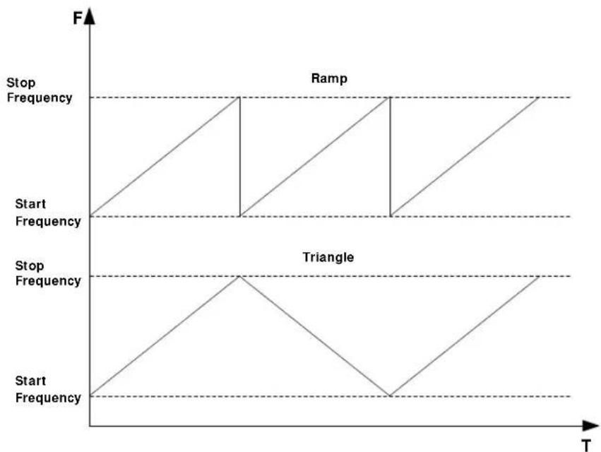
- Sweep Shape
The sweep shape indicates the cycle mode of multiple sweeps.
Press Shape to select “Ramp” or “Triangle” sweep shape. When the sweep direction is “Fwd”, the “Ramp” and “Triangle” sweep shapes are as shown in the figure below.
line
| Start Frequency | Stop Frequency | | --------------- | -------------- | | Start | 0 | | Ramp | High | | Triangle | Low |Ramp: the sweep period always starts from the start frequency or start level to the stop frequency or stop level and the sweep sequence is similar to a ramp waveform.
Triangle: the sweep period always starts from the start frequency or start level to the stop frequency or stop level and then returns back to the start frequency or start level. The sweep sequence is similar to a triangle waveform.
Sweep Mode
Press SWEEP → Mode to select "Cont" or "Single" sweep and the default is "Cont".
- Cont: after selecting continuous sweep, the continuous sweep label is displayed in the frequency or amplitude area in the user interface. When the trigger condition is met, the instrument starts to sweep continuously according to the current setting.
- Single: after selecting single sweep, the single sweep label is displayed in the frequency or amplitude area in the user interface. When the trigger condition is met, the instrument performs one sweep according to the current setting and then stops.
Single Sweep
If the current sweep mode is “Cont”, press Single to switch the sweep mode to “Single” and the instrument will perform one sweep if the trigger condition is met. If the current sweep mode is “Single”, press Single and the instrument will perform one sweep if the trigger condition is met.
Reset Sweep
If the current sweep direction is "Fwd", press Reset Swp, the instrument stops the current sweep and restarts the sweep from the start frequency or start level. If the current sweep direction is "Down", press Reset Swp, the instrument stops the current sweep and restarts the sweep from the stop frequency or stop level.
Trigger Mode
1. Trigger Mode
Select the trigger mode of the whole sweep period.
Press SWEEP and use the page up/down key ▼ to open the 2/3 menu page; then, press Trig Mode to select "Auto", "Key", "Bus" or "Ext" trigger.
NOTE: The following descriptions are valid when the trigger mode of each point in the sweep period is met.
- Auto Trigger
The default mode is auto. If the sweep mode is set to “Cont”, the instrument will start sweeping once a sweep type is selected. If the sweep mode is set to “Single”, press Single to meet the single sweep condition. The instrument will start a sweep and then stops.
● Key Trigger
After selecting "Key" trigger, if the sweep mode is set to "Cont", the instrument starts a sweep each time Trigger at the front panel is pressed. If the sweep mode is "Single", press Single to meet the single sweep condition. After that the instrument starts a sweep and then stops each time Trigger at the front panel is pressed.
- Bus Trigger
After selecting “Bus” trigger, if the sweep mode is set to “Cont”, the instrument starts a sweep each time the “*TRG” command is sent. If the sweep mode is “Single”, press Single to meet the single sweep condition. After that the instrument starts a sweep and then stops each time the
"*TRG" command is sent.
- External Trigger
In external trigger, the RF signal generator accepts the trigger signal input from the [TRRIGERIN] connector (as shown in the figure below) at the rear panel. If the sweep mode is set to "Cont", the instrument starts a sweep each time a TTL pulse signal with specified polarity is received. If the sweep mode is "Single", press Single to meet the single sweep condition. After that the instrument starts a sweep and then stops each time a TTL pulse signal with the specified polarity is received.
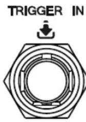
To specify the polarity of the TTL pulse signal, press Trig Slope to select "Pos" or "Neg" and the default is "Pos".
2. Point Trigger Mode
Select the trigger mode of each sweep point in a sweep period.
Press SWEEP and use the page up/down key to open the 2/3 menu page; then, press Point Trig to select "Auto", "Key", "Bus" or "Ext" trigger.
NOTE: The following descriptions are valid when the corresponding trigger mode of sweep period is met.
- Auto Trigger
The default mode is auto. If the sweep mode is set to “Cont”, the instrument will start sweeping each sweep point continuously within a sweep period once a sweep type is selected. If the sweep mode is set to “Single”, press Single to meet the single sweep condition. After that the instrument starts to sweep and then stops after the sweep period is finished.
● Key Trigger
After selecting "Key" trigger, if the sweep mode is set to "Cont", the instrument starts to sweep a point each time Trigger at the front panel is pressed. If the sweep mode is "Single", press Single to meet the single sweep condition. At this point, the instrument starts to sweep a point and stops after the sweep period is finished each time Trigger at the front panel is pressed.
- Bus Trigger
After selecting “Bus” trigger, if the sweep mode is set to “Cont”, the instrument starts to sweep a point each time the “*TRG” command is sent. If the sweep mode is “Single”, press Single to meet the single sweep condition. At this point, the instrument starts to sweep a point and stops after the sweep period is finished each time the “*TRG” command is sent.
- External Trigger
In external trigger mode, the RF signal generator accepts the trigger signal input from the [TRRI GER I N] connector (as shown in the figure below) at the rear panel. If the sweep mode is set to "Cont", the instrument starts to sweep a point each time a TTL pulse signal with specified polarity is received. If the sweep mode is "Single", press Single to meet the single sweep condition. At this point, the instrument starts to sweep a point and stops after the sweep period is finished each time a TTL pulse signal with specified polarity is received.
TRIGGER IN
To specify the polarity of the TTL pulse signal, press Trig Slope to select "Pos" or "Neg" and the default is "Pos".
Explanation
When executing the sweep operation, the priority order of the conditions is Single Sweep → Trigger Mode → Point Trigger Mode. For example, when both the trigger mode and point trigger mode are set to "Key" trigger:
- In “Cont” sweep mode, press Trigger to meet the trigger mode of the whole period and then press Trigger again to meet the trigger mode of points within the sweep period; then, the instrument starts to sweep.
- In “single” sweep mode, press Single to meet the single sweep condition and then press Trigger twice to meet the sweep period trigger mode and point trigger mode respectively. Then, the instrument starts to sweep.
Modulation
Amplitude Modulation (AM)
During amplitude modulation (AM), the modulating signal changes the amplitude of the RF carrier waveform linearly.
To Enable AM
Press AM → Switch to select "On" or "Off".
- On: enable the AM function. The backlight of AM goes on and the AM label is displayed in the function status area in the user interface.
● Off: disable the AM function and this is the default state.
NOTE: When a sweep type is selected, if the step sweep time is lower than 30 ms and amplitude modulation is turned on, "You can turn on the AM when sweep time is greater than 30ms" will be displayed in the user interface.
To Select the Modulation Source
Press AM → Source to select "Int", "Ext" or "Int & Ext" modulation source.
1. Internal Source
After selecting "Int", the internal modulation source is turned on. At this point, the instrument provides the modulating signal and you can set the modulation frequency and modulation waveform of the modulating signal.
2. External Source
After selecting "Ext", Freq and Waveform are grayed out and disabled. The RF signal generator receives the external modulating signal input from the [EXT MOD INPUT] connector (as shown in the figure below) at the front panel. This modulating signal can be any waveform.
EXT MOD INPUT
NOTE: To ensure the modulation performance, the input amplitude of the external modulating signal should be less than ±0.5V .
3. Internal & External
After selecting "Int & Ext", both internal and external modulating sources are selected at the same time and you can perform dual-tone AM signal modulation.
To Set the Modulation Depth
The modulation depth indicates the extent of output amplitude variation and is expressed as a percentage. The range of AM modulation depth is from 0% to 100%.
Press AM → Depth to set the AM modulation depth.
1. Select "Int" modulation source
AM modulation depth ( m_a ) and the amplitude difference ( P_sb ) between the carrier and sidebands satisfy the following relation:
$$ \Delta P = 6 - 2 0 \lg m _ {a s i} $$
- When modulation depth is 0%, the instrument outputs a single frequency carrier signal.
- The greater the modulation depth is, the smaller the difference between the output amplitude and carrier amplitude and the better the symmetry of the output amplitudes of the upper and lower sidebands.
2. Select "Ext" modulation source
- To achieve a modulation depth of 100%, the external modulation source must input a signal (±0.5 V).
- If the external modulation source inputs a signal (±0.25 V), the measured modulation depth is 50%.
3. Select "Int & Ext" modulation source
If modulation depth is set to 50%, the modulation depth of the internal modulation source and that of the external modulation source each is 25% respectively. These parameters meet the relationship: the modulation depth setting = the internal modulation depth + the external modulation depth, and the modulation depth of the internal modulation source equals that of the external modulation source.
To Select the Modulation Waveform
Press AM → Source to select "Int" or "Int & Ext" modulation source; press Waveform to select "Sine" or "Square" and the default is "Sine".
NOTE: When “Ext” modulation source is selected, this menu is grayed out and disabled.
To Set the Modulation Frequency
Press AM → Source to select "Int" or "Int & Ext" modulation source; press Freq to set the frequency of the modulating waveform.
- Use the numeric keyboard or knob to input the desired frequency value.
- For sine waveforms, the range of the modulation frequency is from 100 mHz to 1 MHz.
- For square waveforms, the range of the modulation frequency is from 100 mHz to 20 kHz.
NOTE: When “Ext” modulation source is selected, this menu is grayed out and disabled.
Frequency Modulation (FM)
During frequency modulation (FM), the modulating signal changes the frequency of the RF carrier waveform.
To Enable FM
Press FM/øM → FM/ΦM to select “FM” and press Switch to select “On” or “Off”.
- On: enable the FM function. The backlight of FM/øM goes on and the FM label is displayed in the function status area in the user interface.
- Off: disable the FM function and this is the default state.
NOTE: The frequency modulation and phase modulation cannot be enabled at the same time. In addition, when a sweep type is selected, if the step sweep time is lower than 200 ms and frequency modulation is turned on, "You can turn on the FM or PM when sweep time is greater than 200ms" will be displayed in the user interface.
To Select the Modulation Source
Press FM/øM → Source to select "Int", "Ext" or "Int & Ext" modulation source.
1. Internal Source
After selecting “Int”, the internal modulation source is turned on. At this point, the instrument provides the modulating signal and you can set the modulation frequency and modulation waveform of the modulating signal.
2. External Source
After selecting "Ext", Rate and Waveform are grayed out and disabled. The RF signal generator receives the external modulating signal input from the [EXT MOD INPUT] connector (as shown in the figure below) at the front panel. This modulating signal can be any waveform.
EXT MOD INPUT
NOTE: To ensure the modulation performance, the input amplitude of the external modulating signal should be less than ±0.5V .
3. Internal & External
After selecting "Int & Ext", both internal and external modulating sources are selected at the same time and you can perform dual-tone FM signal modulation.
To Set the Frequency Deviation
The frequency deviation is the deviation of the frequency of the modulating waveform relative to that of the carrier waveform and the unit is Hz.
Press FM/øM → Deviation to set the FM frequency deviation.
- Use the numeric keyboard or knob to input the desired frequency value.
- The different RF frequency setting corresponds to different maximum frequency deviation.
To Select the Modulation Waveform
Press FM/øM → Source to select "Int" or "Int & Ext" modulation source; use the page up/down key ▼ to open the 2/2 menu page and press Waveform to select "Sine" or "Square" and the default is "Sine".
NOTE: When "Ext" modulation source is selected, this menu is grayed out and disabled.
To Set the Modulation Frequency
Press FM/øM → Source to select "Int" or "Int & Ext" modulation source; press Rate to set the frequency of the modulating waveform.
- Use the numeric keyboard or knob to input the desired frequency value.
- For sine waveforms, the range of the modulation frequency is from 100 mHz to 1 MHz.
- For square waveforms, the range of the modulation frequency is from 100 mHz to 20 kHz.
NOTE: When “Ext” modulation source is selected, this menu is grayed out and disabled.
Phase Modulation ( M )
During phase modulation ( M ), the modulating waveform changes the phase of the RF carrier waveform.
To Enable M
Press FM/øM → FM/ΦM to select “ΦM” and press Switch to select “On” or “Off”.
- On: enable the M function. The backlight of FM/ M goes on and the M label is displayed in the function status area in the user interface.
- Off: disable the M function and this is the default state.
NOTE: The frequency modulation and phase modulation cannot be enabled at the same time. In addition, when a sweep type is selected, if the step sweep time is lower than 200 ms and phase modulation is turned on, "You can turn on the FM or PM when sweep time is greater than 200ms" will be displayed in the user interface.
To Select the Modulation Source
Press FM/øM → Source to select "Int", "Ext" or "Int & Ext" modulation source.
1. Internal Source
After selecting “Int”, the internal modulation source is turned on. At this point, the instrument provides the modulating signal and you can set the modulation frequency and modulation waveform of the modulating signal.
2. External Source
After selecting "Ext", Rate and Waveform are grayed out and disabled. The RF signal generator receives the external modulating signal input from the [EXT MOD INPUT] connector (as shown in the figure below) at the front panel. This modulating signal can be any waveform.
EXT MOD INPUT
NOTE: To ensure the modulation performance, the input amplitude of the external modulating signal should be less than ±0.5V .
3. Internal & External
After selecting "Int & Ext", both internal and external modulating sources are selected at the same time and you can perform dual-tone M signal modulation.
To Set the Phase Deviation
The phase deviation is the deviation of the phase of the modulating waveform relative to that of the carrier waveform and the unit is rad.
Press FM/øM → Deviation to set the M phase deviation.
- Use the numeric keyboard or knob to input the desired phase value.
- The different RF frequency setting corresponds to different maximum phase deviation.
To Select the Modulation Waveform
Press FM/øM → Source to select "Int" or "Int & Ext" modulation source; use the page up/down key ▼ to open the 2/2 menu page and press Waveform to select "Sine" or "Square" and the default is "Sine".
NOTE: When “Ext” modulation source is selected, this menu is grayed out and disabled.
To Set the Modulation Frequency
Press FM/øM → Source to select "Int" or "Int & Ext" modulation source; press Rate to set the frequency of the modulating waveform.
- Use the numeric keyboard or knob to input the desired frequency value.
- For sine waveforms, the range of the modulation frequency is from 100 mHz to 1 MHz.
- For square waveforms, the range of the modulation frequency is from 100 mHz to 20 kHz.
NOTE: When "Ext" modulation source is selected, this menu is grayed out and disabled.
Pulse Modulation
During pulse modulation, the RF carrier waveform is modulated by the pulse signal.
To Enable Pulse Modulation
Press Pulse → Switch to select "On" or "Off".
- On: enable the pulse modulation function. The backlight of Pulse goes on and the Pulse label is displayed in the function status area in the user interface.
- Off: disable the pulse modulation function and this is the default state.
NOTE: When a sweep type is selected, if the step sweep time is lower than 50 ms and pulse modulation is turned on, "You can turn on the Pulse Mode when sweep time is greater than 50ms" will be displayed in the user interface.
To Select the Modulation Source
Press Pulse → Source to select "Ext" or "Int" modulation source.
1. Internal Source
After selecting "Int", the internal modulation source is turned on. At this point, the instrument provides the modulating signal and you can set the pulse mode, pulse period and pulse width of the modulating signal.
2. External Source
After selecting "Ext", Mode, Period, Width Trig Mode and Pulse Out are grayed out and disabled. The RF signal generator receives the external pulse signal input from the [PULSE IN/ OUT] connector (as shown in the figure below) at the rear panel as the modulating signal.
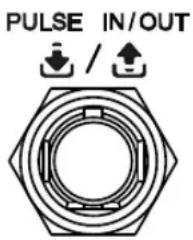
To Select the Pulse Mode
Press Pulse → Source to select "Int" modulation source; press Mode to select "Single", "Double" or "Train" (option PUG-DSG3000).
- Single: only one pulse signal is generated for a pulse period. This is the default pulse mode.
- Double: two pulse signals are generated for a pulse period. At this point, Delay and #2 Width are available and you can set the delay and pulse width.
- Train: a plurality of pulse signals are generated for a pulse period. At this point, Period, Width, Delay and #2 Width are grayed out and disabled. You can press Train List to edit the desired pulse train.
NOTE: When "Ext" modulation source is selected, this menu is grayed out and disabled. When selecting "Train" or editing "Train List", you need to install the option PUG-DSG3000. For the specific installation steps, please refer to DSG3000 Firmware and Options Installation Instruction.
To Set the Pulse Period
The pulse period is the time interval between two neighboring pulses in periodically-repeating pulse sequence.
Press Pulse → Source to select "Int" modulation source; press Period to set the period of the pulse modulating signal.
- Use the numeric keyboard to input the desired value and select the desired unit from the pop-up unit menu or unit keys. You can also press Enter to select the default unit (s).
- You can also use the knob to modify this parameter.
● The range of pulse period is from 40 ns to 170 s. - The pulse period determines the repeating frequency of the internal pulse modulating signal.
NOTE: When "Ext" modulation source or "Train" pulse mode is selected, this menu is grayed out and disabled.
To Set the Pulse Width
The pulse width is the time that the pulse can hold at the maximum value.
Press Pulse → Source to select "Int" modulation source; press Mode to select "Single" or "Double". At this point, you can set the corresponding pulse width and delay.
NOTE: For "Train" pulse width and the related parameter settings, please refer to "Pulse Train List".
1. Single Pulse
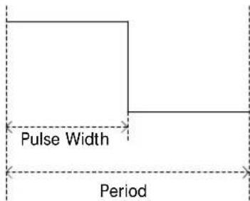
Press Width to set the width of the single-pulse modulating signal.
- Use the numeric keyboard or knob to input the desired pulse width value.
● The range of the pulse width is from 10 ns to 170 s – 10 ns.
● The pulse width is limited by the minimum pulse width and pulse period.
Pulse Width ≥ Minimum Pulse Width
Pulse Width ≤ Pulse Period - 10 ns
2. Double Pulse
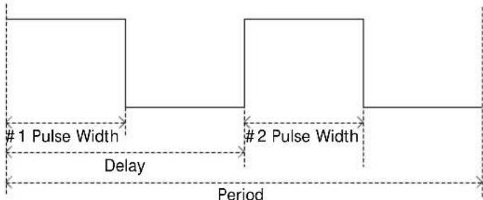
Press Width to set the #1 pulse width of the double-pulse modulating signal.
● Use the numeric keyboard or knob to input the desired pulse width value.
● The range of the #1 pulse width is from 10 ns to 170 s – 10 ns.
● The #1 pulse width is limited by the minimum pulse width and delay.
Pulse Width ≥ Minimum Pulse Width
Pulse Width ≤ Delay - 10 ns
Press #2 Width to set the #2 pulse width of the double-pulse modulating signal.
● Use the numeric keyboard or knob to input the desired pulse width value.
● The range of the #2 pulse width is from 10 ns to 170 s – 10 ns.
- The #2 pulse width is limited by the minimum pulse width, pulse period and delay.
2 Pulse Width ≥ #2 Minimum Pulse Width
2 Pulse Width ≤ Pulse Period - Delay - 10 ns
Press Delay to set the delay from the start of the #1 pulse to the start of the #2 pulse of the double-pulse modulating signal.
- Use the numeric keyboard or knob to input the desired delay value.
● The range of the delay is from 20 ns to 170 s – 20ns.
NOTE: When “Ext” modulation source or “Train” pulse mode are selected, the above-mentioned menus are grayed out and disabled.
To Select the Trigger Mode
Press Pulse → Source to select "Int" modulation source; press Trig Mode to select "Auto", "Ext Trig", "Ext Gate", "Key" and "Bus" trigger mode.
- Auto
The default mode is auto. The RF signal generator meets the trigger condition at any time and will start the pulse modulation once the Pulse function is enabled.
- External Trigger
In external trigger, the RF signal generator accepts the external trigger signal input from the [PULSE IN/ OUT] connector (as shown in the figure below) at the rear panel. The instrument starts a pulse modulation each time a TTL pulse signal with specified polarity is received. To specify the polarity of the TTL pulse, press Trig Slope to select "Pos" or "Neg" and the default is "Pos".
- External Gate
In external gate mode, the RF signal generator accepts the external gated signal input from the [PULSE IN/ OUT] connector at the rear panel. The instrument starts a pulse modulation within the valid level range each time a gated signal with specified polarity is received (as shown in the figure below). To specify the polarity of the gated signal, press Gate Polar to select “Normal” or “Inverse” and the default is “Normal”.
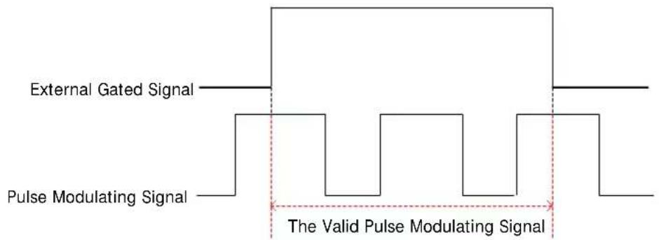
● Key Trigger
In key trigger mode, the instrument starts a pulse modulation each time Trigger at the front panel is pressed.
- Bus Trigger
In bus trigger mode, the instrument starts a pulse modulation each time the "*TRG" command is sent.
NOTE: When "Ext" modulation source is selected, the above-mentioned menus are grayed out and disabled. If "Int" modulation source is selected and "Pulse Out" switch is turned on, Ext Trig and Ext Gate menus are grayed out and disabled.
Pulse Output
Press Pulse → Source to select "Int" modulation source; press Pulse Out to select "On" or "Off".
- On: enable the pulse output function. At this point, the RF signal generator can output the pulse signal generated by internal pulse generator from the [PULSE IN/ OUT] connector at the rear panel. Note, this output signal relates to Mode settings.
● Off: disable the pulse output function and this is the default state.
NOTE: When "Ext" modulation source is selected, this menu is grayed out and disabled.
Trigger Delay
Press Pulse → Source to select "Int" modulation source; after selecting Ext Trig mode, press Trig Delay set the delay from the start of receiving the external trigger signal to the start of the #1 pulse of the pulse modulating signal. As shown in the following below.
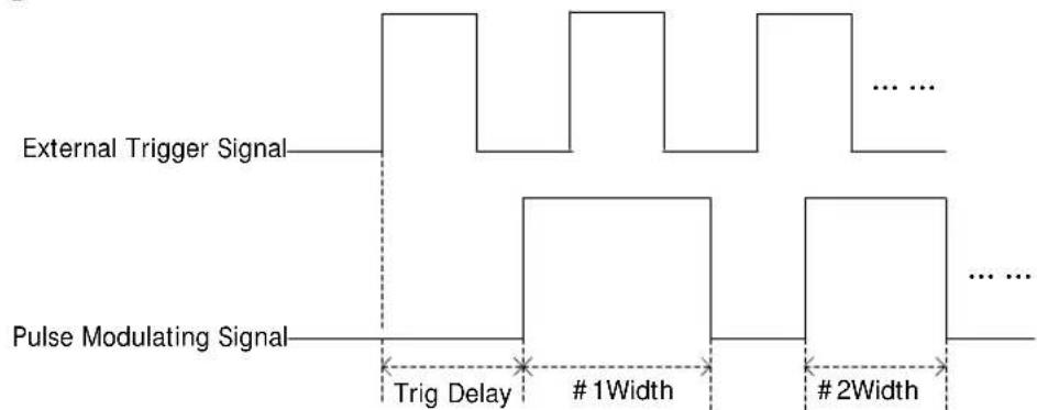
- Use the numeric keyboard or knob to input the desired trigger delay value.
● The range of the trigger delay is from 10 ns to 170 s.
NOTE: When "Ext" modulation source is selected, this menu is grayed out and disabled.
To Set the Polarity
Press Pulse → Polarity to select “Normal” or “Inverse” to set the polarity of the current pulse modulating signal and the default is “Normal”.
Pulse Train List
Press Pulse to use the page up/down key ▼ to open the 3/3 menu page, and then press Train List to enter the editing interface of pulse train list. At this point, you can create pulse train list and store the train list finished in internal or external memory. You can also recall the stored train list when required.
| SN | Line number, indicates the series number of the pulse to be set. You can add and delete rows using Insert and Delete. |
| On Time | It indicates the corresponding high level duration of the pulse to be set. |
| Off Time | It indicates the corresponding low level duration of the pulse to be set. |
| Repeat | It indicates the repetition times of the pulse to be set. |
| Dwell Time | It indicates the duration of the pulse to be set currently. |
The pulse train edited as shown in the figure below, wherein the repeat number of the first line is two.
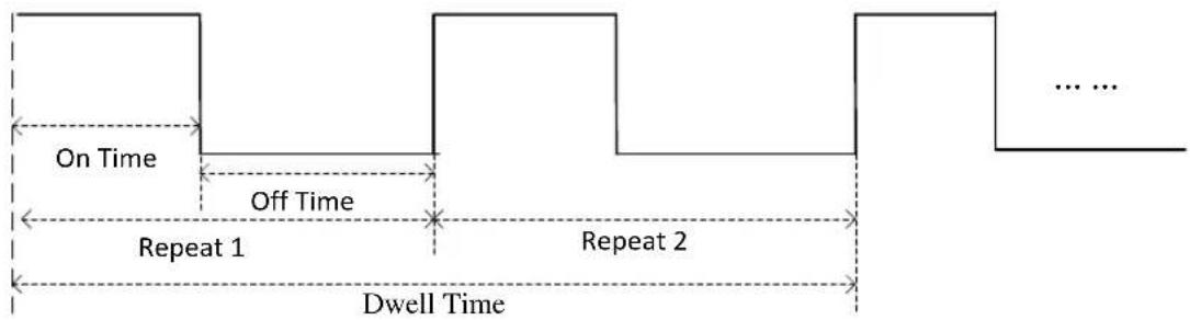
flowchart
graph LR
    A["On Time"] --> B["Off Time"]
    B --> C["Repeat 1"]
    C --> D["Repeat 2"]
    D --> E["Dwell Time"]
    E --> F["... ..."]
NOTE: When editing pulse train list, you need to install the option PUG-DSG3000. For the specific installation steps, please refer to DSG3000 Firmware and Options Installation Instruction.
- Run
Press Run, you can set the current pulse value to the internal modulating signal. At this point, if "Int" modulation source and "Train" pulse mode are selected and "Pulse Out" switch is turned on, the instrument outputs the corresponding pulse sequence from the [PULSE IN/ OUT] connector at the rear panel.
- Insert
Press Insert to insert a row with the same pulse value below the current row. At this point, the number of rows of the pulse train list increases by one.
- Delete
Press Delete to delete the pulse value of the row currently selected. At this point, the number of rows of the pulse train list reduces by one.
- Goto Row
Press Goto Row to select the desired row for edit in the pop-up menu. It is usually used to modify the pulse value of the specified row.
N: press n and use the numeric keyboard to input the desired row number to select that row. The row number input should not be greater than the total number of rows of the current list.
Top: press Top to select the first row of the current list.
Mid: press Mid to select the row at the middle of the current list.
Bottom: press Bottom to select the last row of the current list.
When the desired row is selected, press ↩ to return to the previous menu to modify the calibration value of the row currently selected.
- Load
Press Load to open the store and recall interface. At this point, you can select and read the pulse train list file stored. For detailed operations, refer to the introduction in "Store and Recall". You can edit or modify the train list recalled.
- Store
Press Store to open the store and recall interface. At this point, you can save the pulse train list file currently edited. For the detailed operations, please refer to the introduction in "Store and Recall".
Tips:
Edit pulse train list:
Use the direction keys or knob to select the “On Time”, “Off Time” and “Repeat” of the pulse to be set in the train list. Press the numeric keyboard to input the value and select the desired unit from the pop-up unit menu or unit keys. You can also press Enter to select the default unit s or confirm input.
I / Q Modulation (Option I Q-DSG3000)
I/Q modulation can improve the spectrum utilization. In IQ modulation, two orthogonal carrier signals (with the same frequency and 90° phase difference, generally expressed with Sin and Cos) are modulated with the I (In-Phase component) and Q (Quadrature Phase component) signals respectively and then they are transmitted together.
To Enable I / Q Modulation
Press I / Q → Switch to select "On" or "Off".
- On: enable the I/Q modulation function. The backlight of I/Q goes on and the I/Q label is displayed in the function status area in the user interface.
- Off: disable the I/Q modulation function and this is the default state.
NOTE: When a sweep type is selected, if the step sweep time is lower than 50 ms and I/Q modulation is turned on, "You can turn on the IQ Mode when sweep time is greater than 50ms" will be displayed in the user interface.
To Select the Modulation Source
Press I/Q → Source to select "Int" or "Ext" modulation source.
1. Internal Source
When “Int” is selected, the built-in baseband generator (wavetable) provides the modulating signal. At this point, if the IQ modulation switch is turned on, the baseband output switch is turned on at the same time. The RF signal generator will output the I (In-Phase) components and Q (Quadrature Phase) components of the I/Q modulation baseband signal from the [I OUT] and [Q OUT] connectors (as shown in the figures below) on the rear panel.
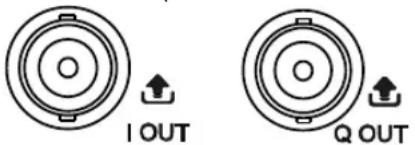
2. External Source
When “Ext” is selected, the RF signal generator receives the in-phase baseband signal and quadrature phase modulating signal of the I/Q modulation input from the [I IN] and [Q IN] connectors (as shown in the figures below) on the rear panel.
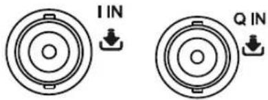
Tip: When an external baseband signal is input and the baseband output switch is turned on, the instrument can output the I (In-Phase) components and Q (Quadrature Phase) components of the I/Q modulation baseband signal generated by the built-in baseband generator (wavetable) from the [I OUT] and [Q OUT] connectors on the rear panel respectively.
Baseband Signal
1. Baseband Output
Press I / Q → BaseBand → Switch to select "On" or "Off".
- On: enable the baseband output function. The RF signal generator outputs the I (In-Phase) and Q (Quadrature Phase) components of the I/Q modulation baseband signal from the [I OUT] and [Q OUT] connectors on the rear panel.
● Off: disable the baseband output function.
2. Baseband Level
Press I/Q → BaseBand → Level to set the amplitude of the baseband output signal.
- Use the numeric keyboard to input the amplitude value and select the desired unit from the pop-up unit menu or unit keys. You can also press Enter to select the default unit (dBm).
● The amplitude units available are V, mV, μV, nV and dBm. - You can press the left/right direction keys to enter the parameter editing state. Then, move the cursor to the specified digit and use the up/down direction keys or knob to modify the parameter value.
- You can also use the up/down direction keys or knob to modify the amplitude at the current step.
- Press Step to set the step.
Tips: When the baseband level unit is set to dBm, this level is converted to the value in Volts and displayed in the menu.
3. ARB
Press I/Q → BaseBand → ARB to enter the store and recall interface. At this time, the message “You can load the ARB files” is displayed in the user interface. Press Enter or the right direction key to unfold the current directory and select the ARB file (namely wavetable file; the format is *.arb) to be loaded. Then press Recall to load this file. The message “File loading succeeded” is displayed after the file is loaded. For more information about how to load a file, please refer to “Store and Recall”.
Tips:
The loadable ARB files should be edited and downloaded to DSG3000 using the Ultra IQ Station PC software. For more information about how to download the ARB file, please refer to Ultra IQ Station Help Document.
4. Clock Frequency
Press I/Q → BaseBand → Clock Freq to set the clock rate of the ARB output. You can modify this parameter using the numeric keyboard or knob.
● The units available are GHz, MHz, kHz and Hz.
- Press Enter to select the default unit (MHz).
- You can press the left/right direction keys to enter the parameter editing state and move the cursor to the specified digit and use the up/down direction keys or knob to modify the parameter value.
- You can also use the up/down direction keys or knob to modify the clock frequency at the current step.
- Press Step to set the step.
NOTE: When loading the ARB file, this value will be automatically set to the clock frequency of the current ARB file.
5. Trigger
1) Trigger Mode
Select the trigger mode of IQ modulation baseband output.
Press Trig Mode to select "Auto", "Key", "Bus" or "Ext".
- Auto Trigger
This is the default mode. The RF signal generator fulfills the trigger condition at any time and it will output the IQ baseband signal continuously.
- Key Trigger
After selecting the "Key" trigger mode, the instrument will output the baseband signal each time Trigger on the front panel is pressed.
- Bus Trigger
After selecting the "Bus" trigger mode, the instrument will output the baseband signal each time the *TRG command is sent.
- External Trigger
When selecting the "Ext" trigger mode, the RF signal generator receives the trigger signal input from the [TRIGGER IN] connector (as shown in the figure below) on the rear panel. The instrument will output the baseband signal each time a TTL pulse signal with the specified polarity is received.
TRIGGER IN
2) Operation Mode
Select the operation mode after the I/Q modulation baseband signal is triggered.
Press Opt Mode to select "Retrig", "Arm Auto", "Arm Retrig" or "Single".
NOTE: When the "Auto" trigger mode is selected, this menu is grayed out and disabled.
- Retrigger
Select the “Retrig” mode. At this point, the instrument outputs the baseband signal continuously and restarts to output the signal each time a trigger is received.
- Arm Auto
After selecting the "Arm Auto" mode, the instrument starts outputting the signal continuously each time a trigger is received until "Arm ARB" is selected and then waits for the next trigger.
- Arm Retrigger
After selecting the "Arm Retrig" mode, the instrument starts outputting the signal continuously each time a trigger is received. The instrument restarts outputting the signal when a trigger is received until "Arm ARB" is selected and then waits for the next trigger.
- Single
After selecting the "Single" mode, the instrument outputs the specified length (specified in "Duration") of waveform each time a trigger is received, and then stops and waits for the next trigger.
3) Arm ARB
Press Arm ARB to manually stop the waveform output and wait for the next trigger.
NOTE: This menu is valid only when the "Arm Auto" or "Arm Retrig" operation mode is selected.
4) Duration Unit
Press Dur Unit to select the duration unit of the IQ modulation wavetable in "Single" trigger.
- SL: take the waveform segment as the unit.
● SA: take the data point as the unit.
5) Duration
Press Duration to set the duration of the single trigger signal.
NOTE: This menu is only available when selecting the “Single” operation mode. This value defines the number of points (N_r) and the instrument acquires the actual time (T_r) according to the current sample rate (S_a) .
They satisfy the following relation: r r / SN_a .
6) External Delay
Press Ext Delay to set the trigger delay when the external trigger signal is received.
NOTE: This menu is only available when selecting the “Ext” trigger mode. This value defines the number of points (N_d) and the instrument acquires the actual time (T_d) according to the current sample rate (S_a) . They satisfy the following relation: T N_d / S_a .
7) External Inhibit
Press Ext Inhibit to set the time from when an external trigger signal is received to when the instrument receives the next trigger signal.
NOTE: This menu is only available when selecting the “Ext” trigger mode. This value defines the number of points (N_i) and the instrument acquires the actual time (T_i) according to the current sample rate (S_a) . They satisfy the following relation: T N_i / S_a .
LF Output
LF output refers to the output of the low-frequency signal generated by the internal generator of the RF signal source. When analog modulation is enabled, LF outputs the internal modulating signal. If the analog modulation is disabled, LF outputs several common waveforms. You can set the frequency and amplitude of the low-frequency signal.
To Enable the LF Output
Press LF to enable the LF output. The backlight of the key goes on and the LF label is displayed in the status bar and the function status area in the user interface. At this point, the [LF OUTPUT] connector (as shown in the figure below) outputs the LF signal according to the current configuration.
LF OUTPUT
To Set the LF Parameters
Press LF to set the “Waveform”, “Level” and “Freq” of the LF output signal.
Explanation
- When the AM or FM/ M function and MOD switch are enabled, and the internal modulation source is selected, Waveform and Freq are grayed out and disabled. At this point, the waveform and frequency of the LF output signal should be set via Waveform and Freq (or Rate) under the AM or FM/ M function and the amplitude of the LF output signal (namely the modulating signal) should be set via Level.
- When all analog modulations which use the internal modulation source are turned on simultaneously and all modulation frequencies and waveforms are consistent, the parameter settings of LF output signal are determined by the last configuration.
- Turn on the MOD switch; any one of the AM or FM/ M function is enabled and “Ext” modulation source is selected; all menus under the LF are grayed out and disabled; you cannot set the frequency and amplitude of the LF output signal. At this point, the actual LF output is consistent with the external modulating signal. When “Int & Ext” modulation source is selected, LF output frequency is half the frequency of internal modulating signal.
To Select the LF Waveform
Press LF Waveform to set the waveform of the LF output signal to "Sine", "Square", "Triangle", "Ramp" or "Swp-Sine" and the default is "Sine".
To Set the LF Amplitude
Press LF Level to set the amplitude of the LF signal.
- Use the numeric keyboard to input the amplitude value and select the desired unit from the pop-up unit menu or unit keys. You can also press Enter to select the default unit (dBm).
● The amplitude units available are V, mV, μV, nV and dBm. - You can press the left/right direction keys to enter the parameter editing state and move the cursor to the specified digit and use the up/down direction keys or knob to modify the parameter value.
- You can also use the up/down direction keys or knob to modify the amplitude at the current step.
- Press Step to set the step.
● The ranges of Sine, Square, Triangle and Ramp waveform amplitude are from 1mV to 3V.
Tips: When the LF level unit is set to dBm, this level is converted to the value in Volts and displayed in the menu.
To Set the LF Frequency
Press LF Freq to set the frequency of the LF signal.
- Use the numeric keyboard to input the frequency value and select the desired unit from the pop-up unit menu or unit keys. You can also press Enter to select the default unit (MHz).
● The frequency units available are GHz, MHz, kHz and Hz. - You can press the left/right direction keys to enter the parameter editing state and move the cursor to the specified digit and use the up/down direction keys or knob to modify the parameter value.
● After setting the frequency, you can use the up/down direction keys or knob to modify the frequency at the current step. - Press Step to set the step.
Explanation
The ranges of sine and sweep-sine frequency are from 100 mHz to 1 MHz. The range of square waveform frequency is from 100 mHz to 20 kHz. The ranges of triangle and ramp waveform frequency are from 100 mHz to 100 kHz.
Sweep-Sine Waveform
The sweep-sine waveform refers to sine waveform changes gradually from the start frequency to stop frequency within the specified time, namely frequency sweep.
1. Select the sweep-sine
Press LF Waveform to select “Swp-Sine”. At this point, the RF signal generator output sweep-sine signal from [LF OUTPUT] connector at the front panel according to the current setting.
2. Set the sweep-sine parameters
- Start Frequency
Press Start Freq, use the numeric keyboard to input the value of the start frequency and select the desired unit from the pop-up unit menu or unit keys. You can also press Enter to select the default unit (MHz).
- Stop Frequency
Press Stop Freq, use the numeric keyboard to input the value of the stop frequency and select the desired unit from the pop-up unit menu or unit keys. You can also press Enter to select the default unit (MHz).
NOTE: After the "Start Freq" or "Stop Freq" is modified, the instrument will restart the sweep and output from the "Start Freq" to "Stop Freq".
- Level
Press Level, use the numeric keyboard to input the value of the amplitude and select the desired unit from the pop-up unit menu or unit keys. You can also press Enter to select the default unit (dBm, this level is converted to the value in Volts and displayed in the menu).
- Sweep Time
The sweep time refers to the duration of a sweep.
Press Sweep Time, use the numeric keyboard to input the time value and
select the desired unit from the pop-up unit menu or unit keys. You can also press Enter to select the default unit (s).
3. Select the sweep mode
Press Mode to select "Cont" or "Single" sweep and the default is "Cont".
- Cont: the instrument sweeps continuously according to the current setting when the trigger condition is met.
- Single: the instrument performs a sweep according to the current setting and then stops when the trigger condition is met.
4. Single Sweep
If the current sweep mode is "Cont", press Single to switch the sweep mode to "single". The instrument starts a sweep if the trigger condition is currently met. If the current sweep mode is "Single", press Single and the instrument starts a sweep if the trigger condition is currently met.
5. Select the sweep shape
The sweep shape refers to the cycle mode of multiple sweeps.
Press Shape to select "Ramp" or "Triangle" and the default is "Triangle".
- Ramp: the sweep period always starts from the start frequency to the stop frequency and the sweep sequence is similar to a ramp waveform.
- Triangle: the sweep period always starts from the start frequency to the stop frequency and then returns back to the start frequency. The sweep sequence is similar to a triangle waveform.
6. Select the trigger mode
Select the trigger mode of the whole sweep period.
Press Trig Mode to select "Auto", "Key", "Bus" or "Ext" trigger.
- Auto Trigger
The default mode is auto. The RF signal generator meets the trigger condition at any time and will start sweeping according to the current setting once “Swp-Sine” is selected.
● Key Trigger After selecting "Key" trigger, if the sweep mode is set to "Cont", the
instrument starts a sweep each time Trigger at the front panel is pressed. If the sweep mode is “Single”, press Single to meet the single sweep condition. After that the instrument starts a sweep and then stops each time Trigger at the front panel is pressed.
- Bus Trigger
After selecting “Bus” trigger, if the sweep mode is set to “Cont”, the instrument starts a sweep each time the “*TRG” command is sent. If the sweep mode is “Single”, press Single to meet the single sweep condition. After that the instrument starts a sweep and then stops each time the “*TRG” command is sent.
- External Trigger
In external trigger, the RF signal generator accepts the trigger signal input from the [TRRIGER IN] connector (as shown in the figure below) at the rear panel. If the sweep mode is set to "Cont", the instrument starts a sweep each time a TTL pulse signal with specified polarity is received. If the sweep mode is "Single", press Single to meet the single sweep condition. After that the instrument starts a sweep and then stops each time a TTL pulse signal with specified polarity is received.
TRIGGER IN
To specify the polarity of the TTL pulse signal, press Trig Slope to select "Pos" or "Neg" and the default is "Pos".
Power Meter (Option PMC-DSG3000)
The DSG3000 can be connected to the USB power sensor or power meter with USB interface via the USB Host interface. In this manual, the Agilent U2004A USB power sensor is taken as an example for description.
After connecting the RF signal source to the AC power supply and turning on it, please refer to DSG3000 Firmware and Options Installation Instruction to activate the power meter controller (option PMC-DSG3000). Then, connect the U2004A USB power sensor to the USB Host interface of the DSG3000. If the message “Power meter connected successfully” is displayed in the user interface, you can use the power meter function.
Press Power Meter to enter the power meter measurement interface as shown in the figure below.
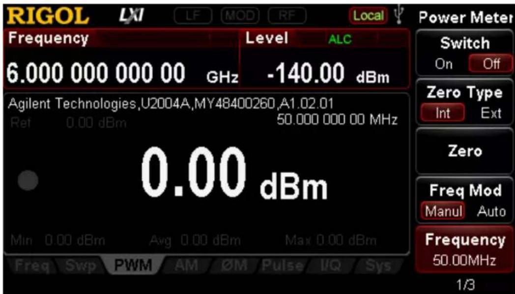
Figure 2-1 Power Meter Measurement Interface
To Enable the Power Meter
Press Switch to select "On" or "Off".
- On: enable the power meter measurement function. The PWM label is displayed in the function status area in the user interface.
● Off: disable the power meter measurement function and this is the default state.
Zero Type
You can execute the power meter zeroing to reduce the zero measurement deviation and the effect of noise to improve the RF power measurement accuracy.
Press Zero Type to select "Int" or "Ext" zero mode.
- Internal zero
When selecting this mode, the power sensor can still be connected with the RF signal during the zeroing process. The instrument uses the internal zero by default after powered-on.
- External zero
When selecting this mode, you must remove the RF signal to be measured before zeroing the power sensor.
Zero
Press Zero and the instrument will perform the power meter zeroing operation according to the “zero type” selected.
Frequency Mode
Select the configuration mode of the measurement frequency.
Press Freq Mod to select "Manul" or "Auto" frequency mode.
- Manul: in this mode, you can manually set the measurement frequency using Frequency softkey.
● Auto: the instrument configures this frequency according to the current output frequency of RF signal generator automatically.
Frequency
Press Frequency to set the measurement frequency manually.
Tips:
When the “Auto” frequency mode is selected, the frequency mode will switch to the “Manul” mode automatically after you set the frequency value via Frequency.
Average Measurement
Average Mode
Press AVG MOD to select "Manul" or "Auto" average measurement mode.
- Manul: in this mode, you can set the “AVG NUM” of the measurement value manually.
- Auto: the instrument configures the "AVG NUM" according to the measurement value of the current signal automatically.
Average Number
Press AVG NUM to set the average number of the signal average measurement manually. The range is from 1 to 1024.
Tips:
- When the "Auto" average mode is selected, the average mode will switch to the "Manual" mode automatically after you set the average number via AVG NUM.
- Increasing the number of averages can reduce the measurement noise, but will increase the measurement time.
Preset
Press Preset and the power meter parameters will be restored to the factory default settings.
Limit Measurement
In limit measurement, the measurement is performed within the specified limit range. If the measurement value exceeds this range, the measurement fails.
Measurement Type
Press Type to select the limit measurement type, including “Upper”, “Lower”, “Both” or “Off”.
- Upper: select the maximum limit measurement. When the alert function is turned on and the measurement value exceeds the maximum limit, the instrument triggers the alarm.
- Lower: select the minimum limit measurement. When the alert function is turned on and the measurement value exceeds the minimum limit, the instrument triggers the alarm.
- Both: both the maximum limit and the minimum limit measurement are selected at the same time. When the alert function is turned on and the measurement value exceeds any one of the maximum or minimum limit, the instrument triggers the alarm.
- Off: disable the limit measurement function. At this time, the instrument is in unlimited measurement. Even if the alert function is turned on, the instrument will not trigger the alarm.
Maximum Limit
Press Max Lmt to set the upper limit of the limit measurement.
Minimum Limit
Press Min Lmt to set the lower limit of the limit measurement.
Alert
Press Alert to select "On" or "Off".
- On: enable the power meter alert function. At this point, if the measurement value exceeds the limit value (the maximum or minimum limit) and the corresponding limit measurement type is selected, the instrument triggers the alarm.
- Off: disable the power meter alert function.
Tips:
- When the beeper is turned on, the beeper sounds and "Alert" (in red) is displayed in the user interface when the power measurement exceeds the specified range.
- When the beeper is turned off, only "Alert" (in red) is displayed in the user interface to indicate that the power measurement exceeds the specified range.
- The detailed alert message is displayed in the message display area of the user interface when the instrument triggers the alarm.
Beeper
Press Beeper to select "On" or "Off".
Recorder
In recording file, the measurement data is saved as a record csv file according to the current parameter settings.
Start
Press Start to start recording the power meter measurement data. The message "Power meter starts recording" is displayed in the user interface.
Stop
Press Stop to stop recording the measurement data. At this point, the message "Power meter stops recording, please save the data" is displayed in the user interface and the instrument enters the store and recall interface. Then, press Enter or the right direction key to unfold the current directory and press Save to store this file. For more information about storing the file, please refer to "Save".
Count
Press Count to set the maximum length of the data that can be currently recorded. The range is from 0 to 65535.
Sample Rate
Press Sample to set the clock rate of the data points recording.
Data Content
Set the data content to be recorded.
Press content to select "All" or "Limit".
● All: record all of the measurement data.
● Limit: only record the limit values of the measurement data.
Relative Measurement
In relative measurement, the instrument computes the measurement result (as a ratio) relative to a reference value.
Switch
Press Switch to select "On" or "Off".
- On: enable the relative measurement mode. At this point, the measurement result and the reference value is displayed in dB (the default unit) in the user interface.
● Off: disable the relative measurement mode.
Mode
Select the setting mode of the relative measurement reference value.
Press Mode to select "Manul" or "Auto".
- Manul: in this mode, you can set the relative measurement reference value using the Ref Value menu manually.
● Auto: the instrument configures the reference value according to the current output level of the RF signal source automatically.
Tips:
When the “Auto” mode is selected, the reference value setting mode will switch to “Manul” automatically after you set the reference value via Ref Value.
Reference Value
Press Ref Value to set the relative measurement reference value.
Statistics
Press Statistics to select "On" or "Off".
- On: enable the statistics function of the measurement data. At this point, the "Min", "Avg" and "Max" labels are displayed in the user interface.
- Off: disable the statistics function of the measurement data. At this point, the "Min", "Avg" and "Max" labels in the user interface are grayed out.
Unit
Press Unit to set the unit of the measurement value. The available units include dBm and Watts.
NOTE: When the “relative measurement” is turned on, the available units are dB and % and the default unit is dB.
System Information
Press Information and the system information of the USB power sensor currently connected is displayed in the text display area of the user interface, including the "Manufacturer", "Model", "SN" and "Version".
RX1000 (Option)
The DSG3000 supports the RX1000 RF Demo Kit provided by RIGOL. Press RX1000 to turn on the RX1000 control interface as shown in the figure below.
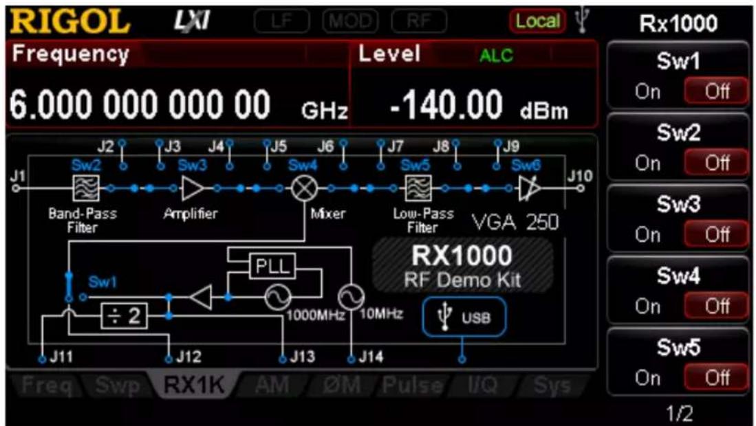
Figure 2-2 RX1000 Control Interface
NOTE: This function is valid only when the RF signal generator is connected with the RX1000 option. For the detailed application of RX1000, please refer to RX1000_ApplicationNote.
Store and Recall
DSG3000 allows users to store various types of files to internal or external memory and recall them when required.
DSG3000 provides a local memory (D disk) and an external memory (E disk).
● D disk: provide storage locations for train list, flatness, sweep list and state files.
- E disk: available when USB storage device is detected at the USB Host interface at the rear panel. You can store the files which the same types as the files saved by D disk to USB storage device.
Press Storage at the front panel to enter the store and recall interface as shown in Figure 2-3.
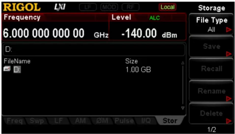
Figure 2-3 store and recall interface
NOTE: DSG3000 can recognize files with filenames consisting of Chinese characters, English characters and numbers. If other characters are used in the file or folder name, it might not be displayed in the store and recall interface normally.
File Type
In the store and recall interface, use the up/down direction keys or knob to select the current saving directory (when USB storage device detected is available, you can switch between D disk and E disk). Press File Type to select the desired file type.
The file types available are "All", "Flatness", "Swp List", "Train List", "AmpCal", "State", "Arb", "Flat csv", "Swp csv", "Train csv", "AmpCal csv" and "Record csv". The default is "All". The description of each file type is as shown in the table below.
NOTE: If you want to select the "Record csv", "AmpCal" or "AmpCal csv" file type, please install the power meter option (PMC-DSG3000) and connect a USB power sensor; otherwise, the menus are grayed out and disabled.
| File Type | Format | Suffix | Explanation |
| Train List | BIN | .TRN | The current train list can be saved by the format of BIN. You can recall it when required. |
| Train csv | CSV | .CSV | The current train list can be saved by the format of CSV. You can copy (for D disk) or save it to a USB storage device. After that the file can be opened and viewed by a spreadsheet program on the computer. |
| Flatness | BIN | .FLA | The current flatness list can be saved by the format of BIN and you can recall it when required. |
| Flat csv | CSV | .CSV | The current flatness list can be saved by the format of CSV. You can copy (for D disk) or save it to a USB storage device. After that the file can be opened and viewed by a spreadsheet program on the computer. |
| Swp List | BIN | .SWP | The current sweep list can be saved by the format of BIN and you can recall it when required. |
| Swp csv | CSV | .CSV | The current sweep list can be saved by the format of CSV. You can copy (for D disk) or save it to a USB storage device. After that the file can be opened and viewed by a spreadsheet program on the computer. |
| State | BIN | .STA | The current system state can be saved by the format of BIN. |
| Record csv | CSV | .CSV | The current data recorded by the power meter can be saved by the format of CSV. You can copy (for D disk) or save it to a USB storage device. After that the file can be opened and viewed by a spreadsheet program on the computer. |
| AmpCal | BIN | .ALC | The current calibration list can be saved by the format of BIN and you can recall it when required. |
| AmpCal csv | CSV | .CSV | The current calibration list can be saved by the format of CSV. You can copy (for D disk) or save it to a USB storage device. After that the file can be opened and viewed by a spreadsheet program on the computer. |
| Arb | BIN | .arb | The arbitrary waveform[1]file saved by theformat of BIN. You can recall the file when required. |
NOTE ^[1] : The wavetable files should be edited and downloaded to the RF signal generator via the Ultra IQ Station PC software.
Tip: You can generate the file of csv format using a spreadsheet program on the computer. Then you can open the file to edit directly the required parameters in the excel table, and save it to USB storage device. In addition, you can also load the file to RF signal generator when required.
Save
1. Select the file type
Please select the desired file type according to the introduction in "File Type".
NOTE: If File Type is set to "All", the save operation is not available.
2. Open the filename input interface
Press Enter or the left/right direction keys to unfold the current directory; press Save to enter the filename input interface. Press +/- C/E/1 to switch among Chinese, English and number input modes.
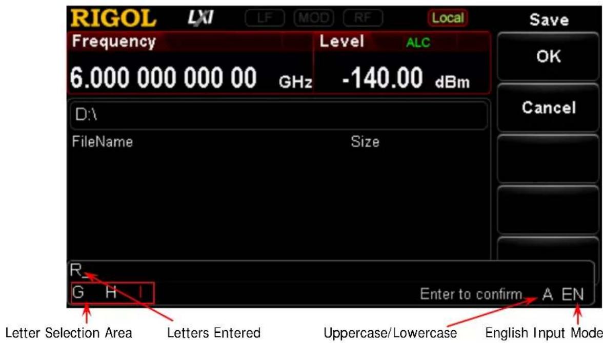
(a) English Input Mode
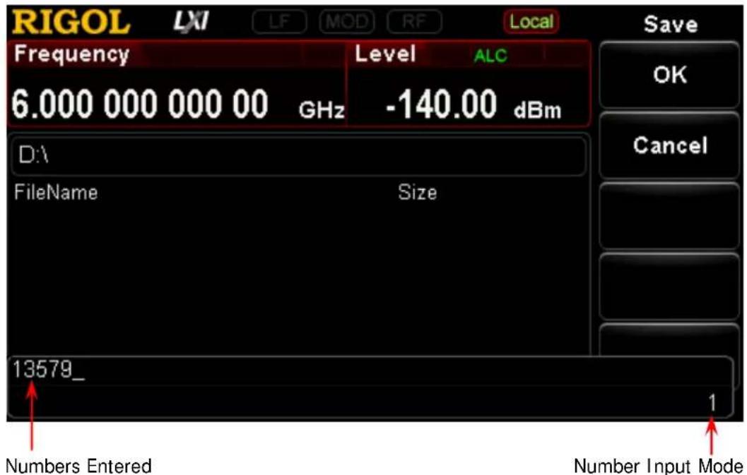
(b) Number Input Mode
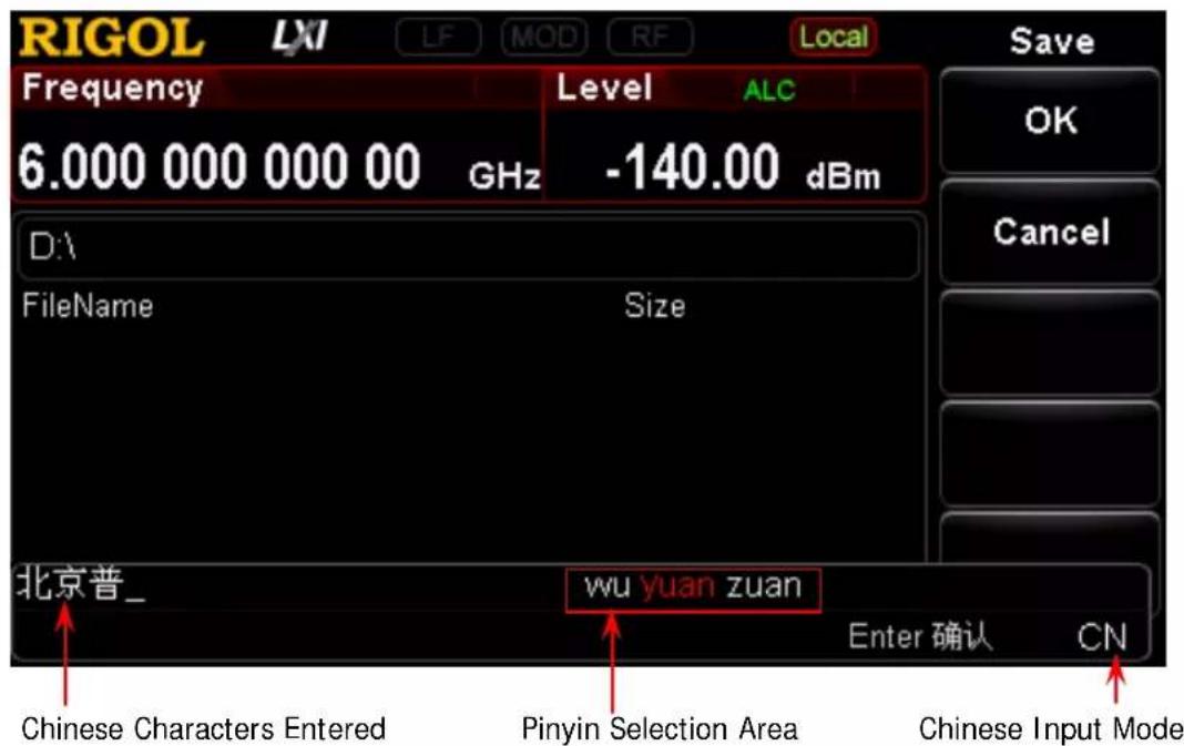
(c1) Chinese Input Mode 1
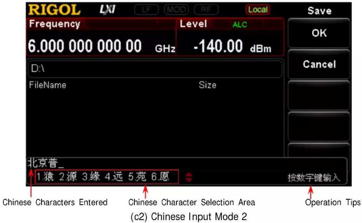
Figure 2-4 Filename Input Interface
3. Input the filename
Input the new filename in the filename input interface. The length of the filename cannot exceed 28 English characters or numbers (or 14 Chinese characters).
- Input English filename
a) Press +/- to switch to English input mode. You can use 1_A/a to switch between uppercase and lowercase. At this point, the corresponding label is displayed at the lower-right corner of the filename input interface.
b) Press the key of the desired letter. At this point, the letters available are displayed in the letter selection area. Press this key continuously or the left/right direction keys or rotate the knob until the background of the desired letter turns red. Then, press Enter to input the letter.
c) Use the above method to input the other letters in the filename.
- Input Chinese filename
a) Press +/- C/E/1 to switch to Chinese input mode. At this point, the corresponding label is displayed at the lower-right corner of the filename input interface.
b) Press the key of the first letter of the pinyin of the desired Chinese character and the pinyins available are displayed in the pinyin selection area. If the desired pinyin is displayed, refer to step c). If the desired pinyin is not displayed, input the whole pinyin and then
refer to c).
c) Press the left/right direction keys or rotate the knob until the background of the desired pinyin turns red. Press Enter to select that pinyin. At this point, the Chinese characters in the Chinese character selection area are numbered. Use the numeric keys to select the desired Chinese character. You can use the up/down direction keys or rotate the knob to open the previous page and next page of the Chinese character selection area.
d) Use the same method to input the other Chinese characters.
- Input number filename
If you want to use numbers as the filename (or a part of the filename), press +/- to switch to number input mode and use the numeric keyboard to input the desired numbers.
4. Save the file
After inputting the filename in the filename input interface, press OK and the RF signal generator will save the file with the specified filename in the specified file type under the directory currently selected. Press Cancel to cancel the save operation.
- Replace File: when the current path has contained a file or folder with the same name, you can press this key to replace the original file or folder.
- Reenter: when the current path has contained a file or folder with the same name, you can press this key to back the filename input interface and reenter the filename.
Recall
After selecting a file stored, press Recall to read the file selected and load it into the system.
Rename
Modify the filename of the stored file.
After selecting a file stored, press Rename to enter the filename input interface, edit a new filename by referring to the introduction in "Input the filename" and press OK to store the file with the new filename.
Delete
After selecting a file stored, press Delete to delete the file selected.
Copy
After selecting a file stored, press Copy to select "Copy" or "Paste".
1. Copy
Copy the file or folder selected under the current directory.
2. Paste
Paste the file or folder.
- When the copy path is the same as the paste path and the current path has contained a file or folder with the same name, the corresponding copy file with the "dup" prefix name is generated after performing paste operation.
- When the copy path is different from the paste path and the current path has contained a file or folder with the same name.
— Replace File: press this key to replace the original file or folder.
— Cancel: press this key to cancel the paste operation.
To Create a Directory
Create a new folder. The length of the folder name cannot exceed 28 English characters or numbers (or 14 Chinese characters).
In the store and recall interface, use the up/down direction keys or knob to select the current saving directory (when USB storage device detected is available, you can switch between D disk and E disk); press Enter or the left/right direction keys to unfold the current directory; press Create Dir to enter the filename input interface, edit the folder name according to the introduction in "Input the filename" and press OK to create an empty folder under the current directory.
Filename Prefix
Press Storage → Name Prefix to select "Prefix State" or "Edit Prefix".
1. Prefix State
Press Prefix State to select "On" or "Off" to enable or disable the prefix edited. When "On" is selected, the edited prefix will be added into the filename input box automatically when saving file.
2. Edit Prefix
Press Edit Prefix to enter the filename input interface and you can use the numeric keyboard to edit the prefix.
Disk Management
Press Storage → Disk Mgr to select "Format D" or "Disk Info".
1. Format D
After selecting "D Disk", press Format D → OK to format the local disk.
2. Disk Information
Press Disk Info to view the disk information including the disk name, type, file system, used space and total space.
System Update
After selecting the update file in the USB storage device, press Storage → Update to update the software of the RF signal generator.
To Set the System Parameters
Set the system-related parameters.
Language
DSG3000 supports Chinese/English menus, help, interface display and Chinese/English input methods.
Press System → Language to select the desired language (“English” or “中文”).
Reset
Press System → Reset to perform “Power On”, “Preset Type” and “Save Preset” operations.
1. Power On
Press Power On to select "Last" or "Preset".
- When “Last” is selected, the system setting before the last power-off will be loaded automatically at power-on.
- When "Preset" is selected, the setting defined in Preset Type will be loaded automatically at power-on.
2. Preset Type
Press Preset Type to select "Factory" or "User".
- When Power On is set to "Preset", the specified preset type will be loaded at power-on.
- After power-on, press Preset at the front panel under any operation interface to recall the specified preset type.
3. Save Preset
Press Save Preset to store the current system state as user-defined setting in the internal non-volatile memory. When Preset Type is set to "User", the current configuration is loaded by recalling "preset".
NOTE: When Preset Type is set to "Factory", this menu is grayed out and disabled.
I / O Configuration
The RF signal generator supports LAN, USB and GPIB interface communication.
Press System → I/O Config to set the "Remote I/O", "LAN" or "GPIB" parameters.
1. Remote I/O
Press Remote I/O to select "LAN", "USB", "GPIB", "Auto" or "Off" all interfaces.
2. LAN
Press LAN to set the LAN parameters.
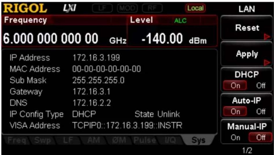
Figure 2-5 To Set the LAN Parameters
- Reset Turn on the DHCP and auto IP and turn off the manual IP. Clear the network password set to restore it to factory setting.
- Apply After configuring LAN parameters, press Apply → OK to effect the configuration.
- DHCP One of the IP address setting methods. Turn on the DHCP and the DHCP server will assign network parameters (such as the IP address, subnet mask and gateway) for the RF signal generator according to the current network configuration.
● Auto-IP One of the IP address setting methods. Turn on the auto IP and the RF signal generator will acquire an IP address from 169.254.0.1 to
169.254.255.254 and subnet mask 255.255.0.0 automatically according to the current network configuration.
- Manual-IP
One of the IP address setting methods. Turn on the manual IP and users can define the IP address of the RF signal generator.
IP
Set the IP address, subnet mask and gateway manually.
a) Press IP Address and use the numeric keyboard to input the desired IP address.
The format of the IP address is nnn.nnn.nnn.nnn. Wherein, the first nnn ranges from 1 to 223 (except 127) and the other three range from 0 to 255. You are recommended to ask your network administrator for an available IP address.
b) Press Sub Mask and use the numeric keyboard to input the desired subnet mask.
The format of the subnet mask is nnn.nnn.nnn.nnn. Wherein, the range of the nnn is from 0 to 255. You are recommended to ask your network administrator for an available subnet mask.
c) Press Gateway and use the numeric keyboard to input the desired gateway.
The format of the gateway is nnn.nnn.nnn.nnn. Wherein, the first nnn ranges from 1 to 223 (except 127) and the other three range from 0 to 255. You are recommended to ask your network administrator for an available gateway.
NOTE: The RF signal generator always tries to acquire the IP address configuration in the order of DHCP, auto IP and manual IP and the three methods cannot be disabled at the same time.
• DNS
Press DNS to set the IP address of the DNS server. The format of the DNS address is nnn.nnn.nnn.nnn. Wherein, the first nnn ranges from 1 to 223 (except 127) and the other three range from 0 to 255. You are recommended to ask your network administrator for an available address.
3. GPI B
Set the GPIB address.
Press GPI B and you can use the numeric keys, knob or direction keys to modify the parameter. The range is from 0 to 30.
Display Setting
Control the screen display.
Press System → Display to set the “Scr State”, “Brightness” and “Time/Date”.
1. Screen State
Press Scr State to set the state of the screen.
- On: the default state. Turn on the screen.
- Off: turn off the screen. At this point, the screen stops updating and is locked. Press Esc to unlock the screen. Screen locking is used during remote operation mode.
2. Brightness
Press Brightness to set the brightness of the LCD backlight of the RF signal generator.
- Use the numeric keys, knob or direction key to modify this parameter.
● The range of the brightness is from 0 to 7.
3. Time/ Date
You can press Time/ Date to set the system time of the RF signal generator.
- Set Time
Set the time displayed on the RF signal generator. The input format of the time is "hhmmss".
For example, 23:12:11 is expressed as 231211.
- Set Date
Set the date displayed on the RF signal generator. The input format of the date is "YYYYMMDD".
For example, 2014/10/21 is expressed as 20141021.
- Time/ Date
Turn on or off the display of the time and date.
Power Status
Press System → Power Status to select "Default" or "Open".
- Default: after the instrument is powered on and the power switch at the rear panel is turned on, you need to press the power key at the front panel to start the instrument.
- Open: after the instrument is powered on and the power switch at the rear panel is turned on, the instrument starts automatically.
Information
Press System → Information to view the “System Info”, “HW Info”, “System Msg” or the “Verbose” of system message.
1. System Information
- Model
- Serial NO.
- FW Version
- Boot Version
- Option
2. Hardware Configuration
- RFB Version
- DB Version
RFB FPGA
RFB CPLD
DB FPGA
DB CPLD
I/Q FPGA - I/Q Board
3. System Message
Display the messages recently displayed.
4. Verbose
Press System Msg to light the Verbose menu. At this point, you can press this softkey to view the complete information of the current row selected in the message list.
License
DSG3000 provides various options to fulfill your measurement requirements. To order the corresponding option, please contact RIGOL.
Press System → License to enter the option management interface in which you can view the option status of the instrument and the license of the option installed as well as install an option.
1. Option Information
Press Option Info and the option status of this instrument will be displayed.
2. License Information
Press License Info and the license of the option installed will be displayed.
3. Install
Press Install and input the option license to activate the corresponding option.
Acquire the license:
1) Order the corresponding option to acquire the option key.
2) Log in the RIGOL official website (www.rigol.com); click "Customer Center" and select "License Generate" to enter the software license generation interface.
3) Input the option key, instrument serial number (press System → Information → System Info to acquire the instrument serial number) and indentifying code; click “Generate” to acquire the corresponding option license.
Tips:
You can also install an option by operating the RF signal generator remotely.
- Build the communication between the RF signal generator and PC. You can use the USB, LAN or GPIB interface. For the connecting methods, please refer to "Remote Control".
- Send the :SYSTem:LKEY
command (for example, :SYSTem:LKEY QA7ZCZEH6AC54SFNKA853MS5CB3A); the RF signal generator identifies the license received and matches it with the corresponding option. At this point, the corresponding option is installed and activated.
Self-test
1. Screen Test
Press Screen Test to enter the screen test interface. The system provides five colors (including white, blue, green, red and black) to test whether the display contains bad pixels. Press any key to switch the screen color and exit the test.
2. Key Test
Press Key Test to enter the key test interface. Press the function keys at the front panel one by one and check whether the corresponding key is illuminated; if not, failure might occur to that key. Press Esc three times to exit the test.
NOTE: If the keys at the front panel are transparent buttons, the corresponding backlight will go on when testing.
Sanitation
Press System → Sanitation to clear all data set by user and restore them to factory settings.
- Format NAND FLASH;
● The user data saved in the NVRAM and NorFlash are restored to factory settings. - HOST NAME, IP address and password in LXI are restored to factory settings.
Chapter 3 Remote Control
DSG3000 series RF signal generator can communicate with USB, LAN and GPIB interfaces. This chapter describes the basic information and methods of remote control.
The contents of this chapter are as follows:
■ Remote Control Overview
■ Control via USB
■ Control via LAN
■ Control Via GPIB
Remote Control Overview
The DSG3000 supports to build communication with the PC via USB, LAN or GPIB interface to realize remote control. The DSG3000 utilizes a SCPI command set (Standard Commands for Programmable Instruments) for remote instrumentation control. There are two modes as follows.
1. User-defined programming
Users can program and control DSG3000 by using the SCPI (Standard Commands for Programmable Instruments) commands. For more information about the commands and programming, refer to the Programming Guide.
2. Use PC software
Users can use the common PC software (Ultra Sigma) provided by RIGOL to send SCPI commands to control DSG3000 remotely.
This chapter will give a detailed introduction of how to use Ultra Sigma to control DSG3000 remotely through various interfaces. Acquire the Ultra Sigma software and install it as well as its components according to the instructions. You can download the latest version of the software from www.rigol.com.
NOTE: When the instrument is in remote mode, Rmt is displayed in the user interface and all the front panel keys (except Esc) are locked. At this point, you can press Esc to exit the remote mode.
Control Via USB
1. Connect the device
Connect the RF signal generator (USB Device) and PC (USB Host) using USB cable.
2. Install USB drive
This RF signal generator is a USBTMC device and the New Hardware Wizard will be displayed after the RF signal generator is correctly connected to the PC (the signal generator will be automatically configured to USB interface) and both of them are started. Please install the "USB Test and Measurement Device (IVI)" drive program according to the instructions.
3. Search for device resource
Start Ultra Sigma and the software will search for the RF signal generator resource currently connected to the PC automatically. You can also click
USB-TMC
to search for the resource manually.
4. View device resource
The instrument model and USB interface information will be displayed under the "RIGOL Online Resource" directory, as shown in the figure below.
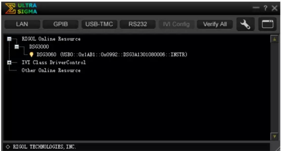
Figure 3-1 View USB Device Resource
5. Communication test
Right-click the resource name "DSG3060
(USB0::0x1AB1::0x0992::DSG3A1301080006::INSTR)” and select “SCPI Panel Control” to open the remote command control panel through which you can send commands and read data. For more information about the SCPI commands,
refer to the Programming Guide.
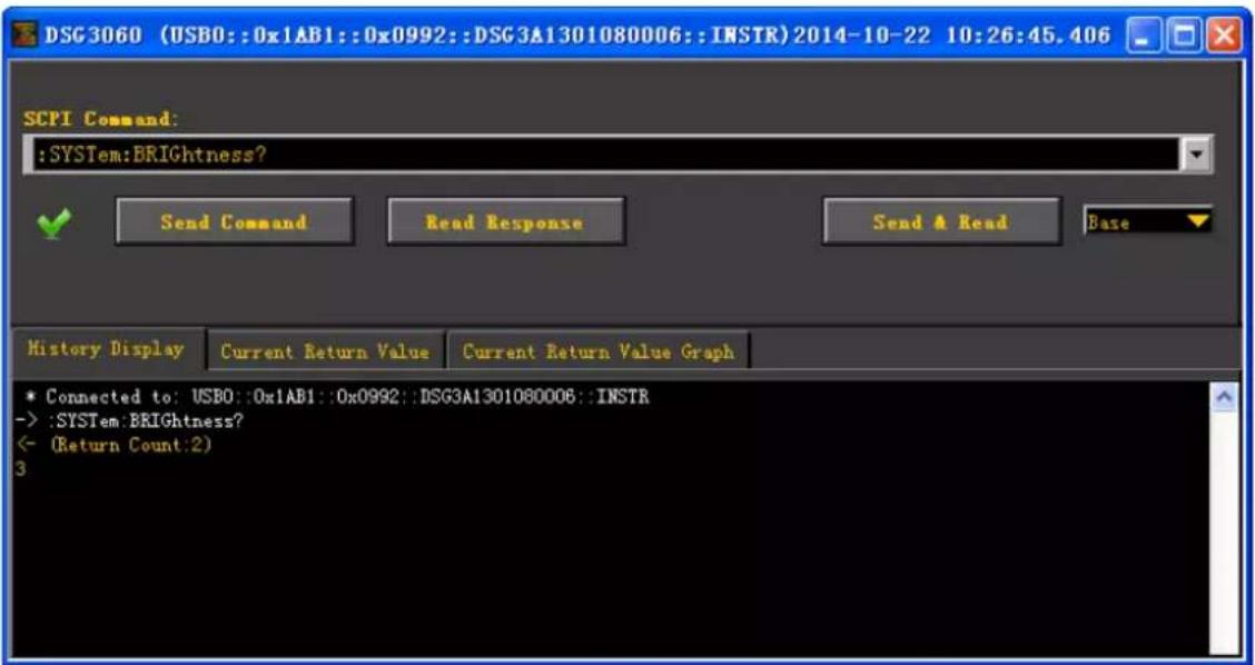
Figure 3-2 Read and Write Command via USB
Control Via LAN
1. Connect the devices
Connect the RF signal generator to your LAN using network cable.
2. Configure LAN parameters
Set the LAN parameters of the RF signal generator according to the description in "I / O Config → LAN".
3. Search device resource
Start-up Ultra Sigma and click LAN, then click in the
pop-up window, the software starts seaching the RF signal generator resources connected to LAN. Instrument resources seached will be displayed in the right of the window. Select your desired resource and click OK, as shown in the following figures.
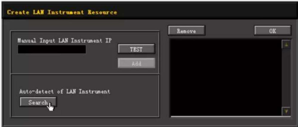
(a)
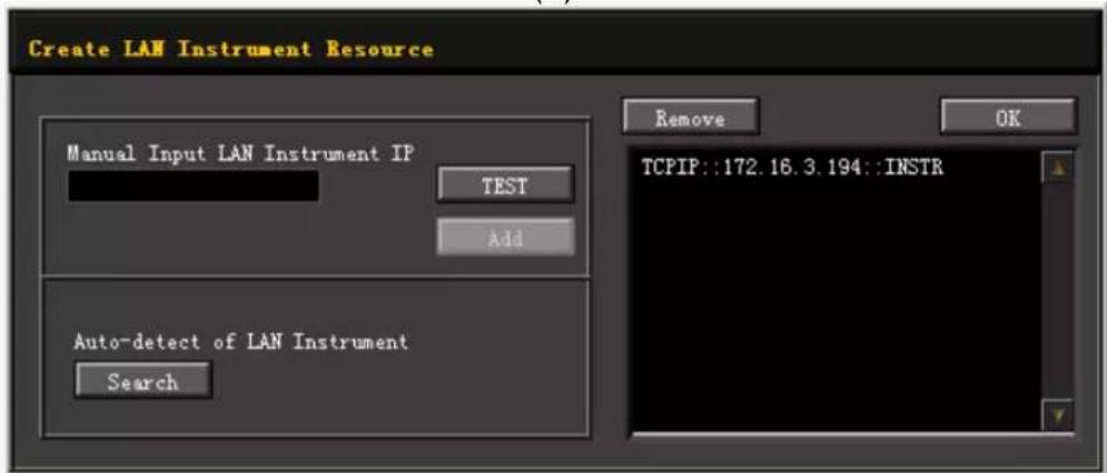
(b)
Figure 3-3 Search LAN resource
NOTE: The resource selected should keep consistency with IP address of the DSG3000 LAN interface.
4. View the resource
The resources that have been searched successfully are shown in the “RIGOL Online Resource” catalog. See figure below.
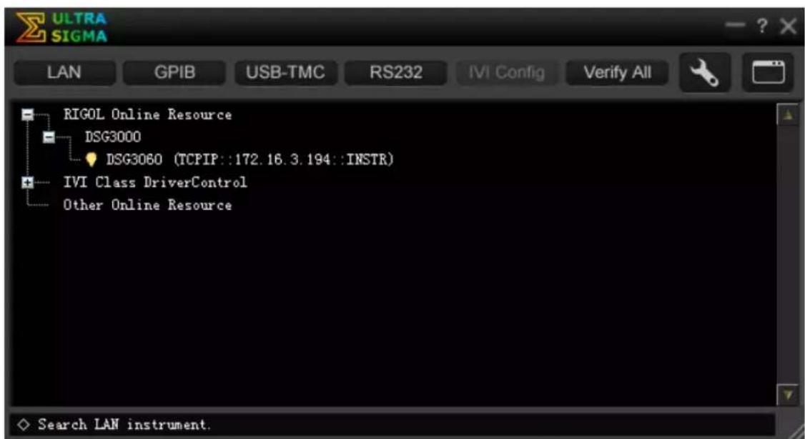
Figure 3-4 View the resource
5. Communication test
Right click the resource name such as DSG3060
(TCPIP::172.16.3.194::INSTR) and select SCPI Panel Control to open the interface below, from which you can write and read commands as shown in the figure below.
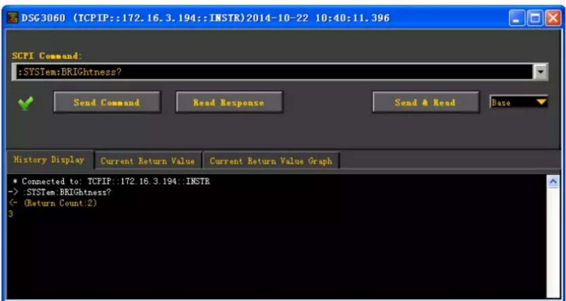
Figure 3-5 Write and read commands via LAN
6. Load LXI webpage
The RF signal generator confirms to LXI Core 2011 Device standards. You can load LXI webpage conveniently by right-clicking the resource name and selecting "LXI-Web". From the webpage, you can see some important information about the instrument such as the model, manufacturer, serial number, description, MAC address and IP address, as shown in the figure below.
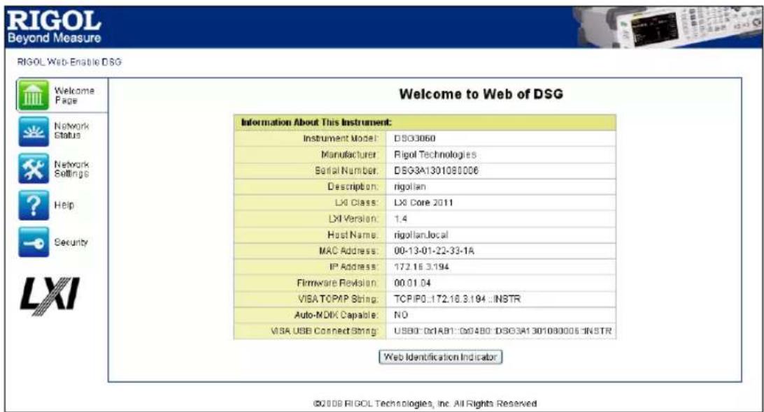
Figure 3-6 LXI Webpage
NOTE: If you want to view or modify the current network setting of the instrument,
click Network Settings and input the initial password "RIGOL" (must be uppercase letters) in the popup window (the user name is empty by default). Besides, you can
Control Via GPI B
1. Connect the devices
Connect the RF signal generator to the PC using GPIB cable.
2. Install the device driver of the GPI B card
Install the driver of the GPIB card which has been connected to the PC.
3. Set the GPI B address
Set the GPIB address following with "I / O Config → GPIB".
4. Search device resource
Start-up the Ultra Sigma and click GPIB to enter the following interface. Then, click Search and the software starts searching the RF signal generator resources that have been connected to PC via GPIB automatically. When a GPIB resource is found, the name of which will be displayed on the right side of the panel.
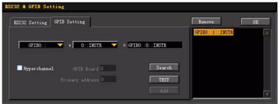
Figure 3-7 GPIB Setting
If resources cannot be found automatically:
- Select the GPIB card address of the PC and RF signal generator from the combo Box of "GPIB::" and "::INSTR" separately.
- Click "Test" to see if the GPIB communication works normally, if not, please follow the prompt messages step by step.
5. View the resource
Click OK and back to the main interface of Ultra Sigma. The resources that have been searched successfully at present are shown in the "RIGOL Online Resource" catalog.
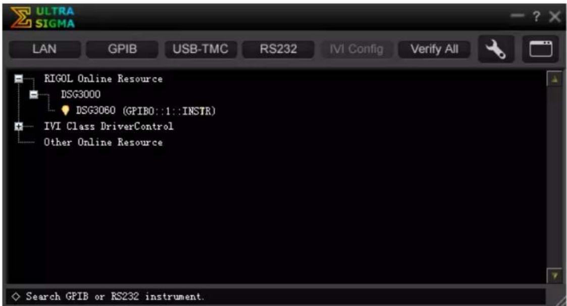
Figure 3-8 View the GPIB resource
6. Communication test
Right-click the resource name such as DSG3060(GPI B0::1::INSTR) and select SCPI Panel Control to open the interface below, from which you can write and read commands, see figure below.
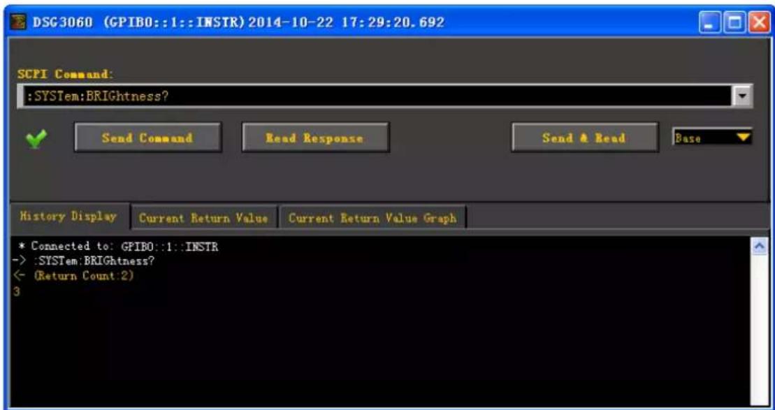
Figure 3-9 Write and read commands via GPIB
Chapter 4 Application Examples
This chapter introduces the basic operations of the instrument as well as a few specific examples so that the user can quickly master the use method of the RF signal generator.
The contents of this chapter are as follows:
■ To Output RF Signal
■ To Output RF Sweep Signal
■ To Output RF Modulated Signal
■ Pulse Train Application
To Output RF Signal
Output a RF signal with 1 GHz frequency and -40 dBm amplitude from the [RF OUTPUT 50Ω] connector.
1. Restore to factory setting
Press System → Reset → Preset Type → "Factory" and then press Preset to restore the factory setting (by default, the frequency offset is 0 Hz and the amplitude offset is 0 dB).
2. Frequency setting
Press FREQ → Frequency, use the numeric keyboard to input the frequency value (1) and select the desired unit (GHz) from the pop-up unit menu or unit keys.
● The frequency units available are GHz, MHz, kHz and Hz.
- Pressing Enter to select the current frequency unit by default.
- You can also press the left/right direction keys to enter the parameter editing state and move the cursor to the specified digit and then use the up/down direction keys or knob to modify the value.
- After the frequency is set, you can use the up/down direction keys or knob to modify the frequency at the current step value.
- Press FREQ → Frequency and then press Step to set the step value.
3. Amplitude setting
Press LEVEL → Level, use the numeric keyboard to input the amplitude value (-40) and select the desired unit (dBm) from the pop-up unit menu or unit keys. You can also press Enter to select the default unit dBm.
● The amplitude units available are dBm, -dBm, mV, uV and nV.
- You can also press the left/right direction keys to enter the parameter editing state and move the cursor to the specified digit and then use the up/down direction keys or knob to modify the value.
- You can also use the up/down direction keys or knob to modify the amplitude at the current step value.
- Press LEVEL → Level and then press Step to set the step value.
4. Enable the RF output
Press RF, the backlight goes on and the RF label is displayed in the status bar of the user interface. The RF output is enabled. At this point, the [RF OUTPUT 50Ω] connector outputs RF signal according to the current configuration.
To Output RF Sweep Signal
This section introduces how to output a RF sweep signal by configuring continuous linear step sweep. Set the frequency range to 1 GHz \~ 2 GHz, the amplitude range to -20 dBm \~ 0 dBm, the number of sweep points to 10 and the dwell time to 500 ms.
1. Restore to factory setting
Press System → Reset → Preset Type → “Factory” and then press Preset to restore the factory setting (by default, the sweep mode is continuous, the sweep type is step and the sweep space is linear).
2. Step sweep parameter setting
Press SWEEP and use the menu page up/down key to turn to the 2/3 menu page; then, press Step Swp to enter the step sweep parameter setting interface.
- Start Frequency
Press Start Freq, use the numeric keyboard to input the start frequency value (1) and select the desired unit (GHz) from the pop-up unit menu or unit keys.
- Stop Frequency
Press Stop Freq, use the numeric keyboard to input the stop frequency value (2) and select the desired unit (GHz) from the pop-up unit menu or unit keys.
- Start Level
Press Start Lev, use the numeric keyboard to input the start level value (-20) and select the desired unit (dBm) from the pop-up unit menu or unit keys. You can also press Enter to select the default unit (dBm).
- Stop Level
Press Stop Lev, use the numeric keyboard to input the stop level value (0) and select the desired unit (dBm) from the pop-up unit menu or unit keys. You can also press Enter to select the default unit (dBm).
- Sweep Points
Press Points, use the numeric keyboard to input the number of sweep points (10) and then press OK or Enter.
- Dwell Time
The dwell time indicates the duration of a sweep step.
Press Dwell Time, use the numeric keyboard to input the time value (500) and select the desired unit (ms) from the pop-up unit menu or unit keys.
3. Enable the RF sweep
Press SWEEP → Sweep and select “Freq & Level” to enable the frequency and amplitude sweep functions at the same time.
At this point, the RF signal generator sweeps from the start frequency and level to the stop frequency and level continuously at certain step according to the current settings. The frequency and amplitude sweep progress bars as well as the continuous sweep label are displayed in the frequency and amplitude areas in the user interface respectively.
4. Enable the RF output
Press RF, the backlight goes on and the RF label is displayed in the status bar of the user interface. The RF output is enabled. At this point, the [RF OUTPUT 50Ω] connector outputs RF sweep signal according to the current configuration.
To Output RF Modulated Signal
This section introduces how to output an AM modulated signal. Set the carrier frequency to 800 MHz, the carrier amplitude to -20 dBm, the AM modulation depth to 60% and the modulation frequency to 20 kHz.
1. Restore to factory setting
Press System → Reset → Preset Type → "Factory" and then press Preset to restore the factory setting (by default, the modulation source is internal and the modulation waveform is sine).
2. Set the carrier frequency and amplitude
(1) Carrier Frequency
Press FREQ → Frequency, use the numeric keyboard to input the frequency value (800) and select the desired unit (MHz) from the pop-up unit menu or unit keys.
(2) Carrier Amplitude
Press LEVEL → Level, use the numeric keyboard to input the amplitude value (-20) and select the desired unit (dBm) from the pop-up unit menu or unit keys. You can also press Enter to select the default unit (dBm).
3. Set the AM modulation parameters
(1) Press AM to enter the amplitude modulation parameter setting interface.
(2) Press Depth, use the numeric keyboard to input the value of the modulation depth (60) and select the desired unit (%) from the pop-up unit menu or by pressing Enter.
(3) Press Freq, use the numeric keyboard to input the frequency value (20) and select the desired unit (kHz) from the pop-up unit menu or unit keys.
(4) Press Switch and select "On" to enable the AM function. The backlight of AM goes on.
4. Enable the RF modulation output
Press MOD and the backlight goes on. Then, press RF and the backlight goes on. The MOD and RF labels are displayed in the status bar of the user interface. The RF modulation output is enabled. At his point, the [RF OUTPUT 50Ω] connector outputs RF modulated signal according to the current configuration.
NOTE: The backlights of RF and MOD should be lit.
Pulse Train Application
Output a user-defined pulse train from [PULSE IN/ OUT] connector. The specific parameters to be set in the pulse list as shown in the table below.
| SN | On Time | Off Time | Repeat |
| 1 | 10ms | 30ms | 2 |
| 2 | 20ms | 40ms | 1 |
1. Restore to factory setting
Press System → Reset → Preset Type → “Factory” and then press Preset to restore the factory setting.
2. Install Pulse Train Generator (Option)
Please refer to DSG3000 Firmware and Options Installation Instruction to install and activate the pulse train generator (option PUG-DSG3000).
3. Edit the Pulse Train List
Press Pulse to use the page up/down key ▼ to open the 3/3 menu page, and then press Train List to enter the editing interface of pulse train list.
- Insert
If the parameter values in the current list are the only one row, press Insert to insert a row with the same pulse value below the current row.
- Delete
If the parameter values in the current list are more than two lines, you can press Delete to delete the pulse value of the row currently selected, and last retain the only two rows parameters.
- Edit
Use the direction keys or knob to move the cursor and select the parameters of the first row to be edited.
— On Time: use the numeric keyboard to input the value 10, and select the desired unit (ms) from the pop-up unit menu or unit keys.
— Off Time: use the numeric keyboard to input the value 30, and select the desired unit (ms) from the pop-up unit menu or unit keys.
— Repeat: use the numeric keyboard to input the value 2, and then press Enter softkey or Enter.
— Use the same method to set the pulse parameters of the second row.
NOTE: Dwell time is calculated automatically by the three parameters (On Time, Off Time and Repeat) to be set.
- Run
Press Run, you can set the current pulse value to the internal modulating signal.
4. Select the Pulse Mode
Press Pulse → Source to select "Int" modulation source; press Mode to select "Train".
5. Enable the Pulse Output
Press Pulse Out, and select "On" to enable the pulse output function. At this point, the RF signal generator can output the pulse signal generated by internal pulse train generator from the [PULSE IN/ OUT] connector at the rear panel.
Chapter 5 Troubleshooting
The chapter lists the commonly encountered failures and their solutions. When you encounter those problems, please solve them following the corresponding steps. If the problem remains still, please contact RIGOL and provide your device information (System → Information → System Info).
1. The screen of the RF signal generator is still dark (no display) after pressing the power key:
(1) Check whether the fan is running;
— If the fan is running but the screen is dark, the screen connecting wire might be loose. — If the fan is not running and the instrument does not start successfully, please go to step (2).
(2) Check whether the power is correctly connected and the power switch is really on.
(3) Check whether the fuse is burned out. If the fuse needs to be replaced, please use the specified fuse (AC 250V, T2A).
(4) Restart the instrument after finishing the above inspections.
(5) If it still does not work correctly, please contact RIGOL.
2. The screen is too dark and cannot be seen clearly:
(1) Check whether the brightness setting of the LCD screen is too low.
(2) Press System → Display → Brightness and use the numeric keys or up/down direction keys to adjust the brightness of the LCD screen of the RF signal generator to a proper value.
3. The RF signal generator is locked:
(1) Check whether the RF signal generator is in remote control mode (in remote control, Rmt is displayed in the status bar of the user interface). Pressing Esc can exit the remote control mode and unlock the front panel.
(2) Check whether the RF signal generator is in local mode with the screen being locked (when the screen is locked, front panel operations are not available). Pressing Esc can unlock the screen and exit the locking state.
(3) If progress bar is displayed on the screen of the signal generator, some operation is in progress. For example, when saving a file, the progress bar will be displayed indicating that the save operation is in progress. At this point, the front panel is locked.
(4) Pressing Preset or restarting the signal generator can also unlock the instrument.
4. The setting is correct but the waveform output is incorrect:
(1) There is no RF output
— Check whether the signal connecting cable is tightly connected to the corresponding [RF OUTPUT 50Ω] connector.
— Check whether the connecting cable has internal damage.
— Check whether the connecting cable is tightly connected to the test instrument.
— Check whether the backlight of RF goes on. If not, press this key to illuminate the backlight. At this point, the RF label is displayed in the status bar of the user interface and the RF output is enabled.
— Check whether the output amplitude of the RF signal is too small. Adjust the output amplitude properly.
(2) The RF output is not modulated
— Check whether the signal connecting cable is tightly connected to the corresponding [RF OUTPUT 50Ω] connector.
— Check whether the connecting cable has internal damage.
— Check whether the connecting cable is tightly connected to the test instrument.
— Check whether the backlights of MOD and RF are both illuminated and check whether the modulation Switch is set to "On".
— Check whether the modulation parameter setting is correct and adjust the parameter appropriately.
— If external modulation source is used, make sure that the external source is correctly connected and outputs signal. At the same time, the external source should work within the specified range of the signal generator.
5. The sweep is abnormal:
(1) The seep stagnates
The sweep progress bar is displayed in the frequency area/amplitude area in the user interface indicating that the sweep is in progress. If the sweep stagnates, please check:
— At least one manner of sweep is enabled. Press SWEEP → Sweep to select “Freq”, “Level” or “Freq & Level”.
— If single sweep mode is selected, press Single and the instrument performs a sweep if the trigger condition is met.
— If the sweep trigger mode is not set to auto, press SWEEP → Trig → "Auto" to make sure whether the sweep stagnates due to the loss of sweep trigger.
— If the point trigger mode is not set to auto, press SWEEP → Point Trig → “Auto” to make sure whether the sweep stagnates due to the loss of point trigger.
— Make sure whether the dwell time is too large or too small that the sweep cannot be seen.
— Make sure that at least two points are set in the step sweep or list sweep.
(2) The dwell time of list sweep is incorrect
— Press SWEEP → List Swp to enter the sweep list editing interface.
— Make sure whether the dwell time of the list sweep is correct.
— If the dwell time is incorrect, re-edit it. If it is correct, turn to the next step.
— Press SWEEP → Sweep Type to make sure that “List” sweep is selected.
If “Step” sweep is currently selected, the signal generator sweeps according to the dwell time of the step sweep.
(3) The list sweep information recalled from the register is lost
— The list sweep information cannot be stored in the status register of the instrument as a part of the instrument state.
— The signal generator can only use the current list for sweep and you can store the list sweep data to the local directory of the instrument.
(4) In list or step sweep, the amplitude does not change
— Make sure that the sweep manner is set to “Level” or “Freq&Level”.
— If the sweep manner is currently set to "Freq", the amplitude will not change.
6. The USB storage device cannot be recognized:
(1) Check whether the USB storage device can work normally when connected to other instrument or PC.
(2) Make sure that the USB storage device used is a Flash type. This instrument does not support hardware USB storage device.
(3) Restart the instrument and insert the USB storage again to check whether it can work normally.
(4) If the USB storage device still cannot be used normally, please contact RIGOL.
7. No response or incorrect response when key is pressed:
(1) After starting the instrument, make sure that whether all the keys are irresponsive.
(2) Press System → Self-test → Key Test to enter the keyboard test interface. Press the function keys at the front panel sequentially and check whether some key gives no response or incorrect response when it is pressed.
(3) If the above failures occur, the keyboard connecting wire might be loose or the keyboard is damaged. Please do not disassemble the instrument and contact RIGOL.
8. Performance specification test is not passed:
(1) Check whether the RF signal generator is within calibration period (1 year).
(2) Make sure that the RF signal generator is warmed up for at least 40 minutes before test.
(3) Check whether the RF signal generator is under the specified temperature.
(4) Check whether the test is being performed in a highly magnetic environment.
(5) Check whether the power supplies of RF signal generator and test system have strong interference.
(6) Check whether the performance of the test device meets the requirement.
(7) Make sure that the test device is within calibration period.
(8) Check whether the test device meets the required conditions of the manual.
(9) Check whether all connections are tight.
(10) Check whether all cables have internal damage.
(11) Make sure that the operations conform to settings and processes which are required by the performance verification manual.
(12) Check whether the error calculation is a mistake.
(13) The definitions of “Typical Value” and “Nominal Value” for this product should be correctly understood.
— Typical Value: the performance specification of this product under specified conditions.
— Nominal Value: the approximate quantity of the product during application.
Chapter 6 Specifications
This chapter describes the specifications and general specifications of RF signal generator. Specifications are valid under the following conditions: the instrument in the calibration cycle is stored at least two hours at 0^ C to 50^ C temperature, and 40 minutes warm up. The specifications include measurement uncertainty. Data represented in this manual are specifications unless otherwise noted.
Typical (typ.): describes characteristic performance, which 80 percent of the measurement results will meet at room temperature (approximately 25^ C). This data is not warranted, does not include measurement uncertainty.
Nominal (nom.): indicates the expected mean or average performance, or an attribute whose performance is by design, such as the 50 ohm connector. This data is not warranted and is measured at room temperature (approximately 25^ C).
Measured (meas.): describes an attribute measured during the design phase for purposes of communicating expected performance, such as amplitude drift vs. time. This data is not warranted and is measured at room temperature (approximately 25^ C).
NOTE: All values represented in this chapter are the measurement results of multiple instruments at room temperature unless otherwise noted.
Specifications
Frequency
| Frequency | ||
| Frequency range | DSG3030 | 9kHz to 3GHz |
| DSG3060 | 9kHz to 6GHz | |
| Frequency resolution | 0.01Hz | |
| Setting time | <10ms[1] (typ.) | |
| Phase offset | Adjustable in 0.01° steps (nom.) | |
| Frequency Band | ||
| Band | Frequency | N[2] |
| 1 | f ≤ 23.4375MHz | 1 |
| 2 | 23.4375MHz < f ≤ 46.875MHz | 0.03125 |
| 3 | 46.875MHz < f ≤ 93.75MHz | 0.0625 |
| 4 | 93.75MHz < f ≤ 187.5MHz | 0.125 |
| 5 | 187.5MHz < f ≤ 375MHz | 0.25 |
| 6 | 375MHz < f ≤ 750MHz | 0.5 |
| 7 | 750MHz < f ≤ 1500MHz | 1 |
| 8 | 1500MHz < f ≤ 3000MHz | 2 |
| 9 | 3000MHz < f ≤ 6000MHz | 4 |
| Internal Reference Frequency | ||
| Reference frequency | 10MHz | |
| Temperature stability | In temperature range 0°C to 50°C, reference to 25°C | <0.5ppm |
| With OCXO-A08 option | <5ppb | |
| Aging rate | <1ppm/year | |
| With OCXO-A08 option | <30ppb/year | |
| Output for internal reference frequency | Frequency | 10MHz |
| Level | +8dBm (typ.) | |
| Output impedance | 50Ω (nom.) | |
| Input for external reference frequency | Frequency | 10MHz |
| Level | 0dBm to +10dBm | |
| Maximum deviation | ±5ppm | |
| Input impedance | 50Ω (nom.) | |
| Frequency Sweep | ||
| Operating mode | Step sweep (equally or logarithmically spaced frequency steps) List sweep (the list of arbitrary frequency steps) | |
| Sweep mode | Single, continuous | |
| Sweep range | Full frequency range | |
| Sweep shape | Triangle, ramp | |
| Step change | Linear or logarithmic | |
| Number of points | Step sweep | 2 to 65535 |
| List sweep | 1 to 6001 | |
| Dwell time range | 20ms to 100s | |
| Triggering | Auto, trigger key, external, bus (GPIB, USB, LAN) | |
| Spectral Purity [3] | ||
| Harmonic | CW mode, 1MHz ≤ f ≤ 6GHz, level ≤ +13dBm | <-30dBc |
| Sub harmonic | CW mode | |
| f ≤ 3GHz | <-65dBc, < -80dBc (typ.) | |
| 3GHz < f ≤ 6GHz | <-52dBc, < -70dBc (typ.) | |
| Non harmonic | CW mode, level > -10dBm, carrier offset > 10kHz | |
| f ≤ 1.5GHz | <-64dBc, < -70dBc (typ.) | |
| 1.5GHz < f ≤ 3GHz | <-58dBc, < -64dBc (typ.) | |
| 3GHz < f ≤ 6GHz | <-52dBc, < -58dBc (typ.) | |
| SSB phase noise | CW mode, at 20kHz carrier offset, 1Hz measurement bandwidth | |
| f = 100MHz | <-120dBc/Hz | |
| f = 1GHz | <-108dBc/Hz, < -110dBc/Hz (typ.) | |
| f = 3GHz | <-102dBc/Hz, < -104dBc/Hz (typ.) | |
| f = 6GHz | <-96dBc/Hz, < -98dBc/Hz (typ.) | |
| Residual FM | RMS value at f = 1GHz, CW | |
| 0.3kHz to 3kHz | <5Hz rms, <1Hz rms (typ.) | |
| 0.03kHz to 20kHz | <30Hz rms, <8Hz rms (typ.) | |
Level
| Setting Range | |||
| Specification level range | Setting range | ||
| Maximum output level | 9kHz ≤ f < 100kHz | +7dBm | +10dBm |
| 100kHz ≤ f < 1MHz | +13dBm | +15dBm | |
| 1MHz ≤ f ≤ 3GHz | +13dBm | +25dBm | |
| 3GHz < f ≤ 6GHz | +13dBm | +20dBm | |
| Minimum output level | 9kHz ≤ f < 100kHz | -110dBm | -120dBm |
| 100kHz ≤ f ≤ 6GHz | -130dBm | -140dBm | |
| Setting resolution | 0.01dB | ||
| Absolute Level Uncertainty[1] | ||||
| Level uncertainty | +13 to -60dBm | -60 to -110dBm | -110 to -130dBm | |
| 9kHz ≤ f < 100kHz | ≤0.5dB (typ.) | ≤0.7dB (typ.) | ||
| 100kHz ≤ f ≤ 3GHz | ≤0.7dB, ≤0.5 (typ.) | ≤0.9dB, ≤0.5 (typ.) | ≤0.7dB (typ.) | |
| 3GHz < f ≤ 6GHz | ≤0.9dB, ≤0.5 (typ.) | ≤1.1dB, ≤0.5 (typ.) | ≤0.9dB (typ.) | |
| VSWR[2] | 1MHz ≤ f ≤ 6GHz | <1.8 (typ.) | ||
| Level Setting | ||
| Setting time | ALC state on, frequency fixed, temperature range: 20°C to 30°C | ≤5ms (typ.) |
| Uninterrupted level setting range | ATT fixed mode, ALC state on, level range -110dBm to +13dBm | >20dB (typ.) |
| Max. Reverse Power | ||
| Max. reverse power | Max. DC voltage | 50V |
| 1MHz < f ≤ 6GHz | 10W | |
| Level Sweep | ||
| Operating mode | Step sweep (equally spaced level steps)List sweep (the list of arbitrary level steps) | |
| Sweep mode | Single, continuous | |
| Sweep range | Full level range | |
| Sweep shape | Triangle, ramp | |
| Step change | Linear | |
| Number of points | Step sweep | 2 to 65535 |
| List sweep | 1 to 6001 | |
| Dwell time range | 20ms to 100s | |
| Triggering | Auto, trigger key, external, bus (GPIB, USB, LAN) | |
Internal Modulation Generator (LF)
| Internal Modulation Generator (LF) | ||
| Waveform | Sine, square, triangle, ramp, sine sweep | |
| Frequency range | Sine, sine sweep | 0.1Hz to 1MHz |
| Square | 0.1Hz to 20kHz | |
| Triangle, ramp | 0.1Hz to 100kHz | |
| Resolution | 0.01Hz | |
| Frequency error | Same as RF reference source | |
| Output voltage[1] | Setting range | 1mV to 3V |
| Resolution | 1mV | |
| Output impedance | 50Ω (nom.) | |
| Sine sweep | Sweep mode | Single, continuous |
| Sweep range | Frequency range of LF output | |
| Sweep time | 1ms to 1000s | |
| Sweep shape | Triangle, ramp | |
| Triggering | Auto, trigger key, external, bus (GPIB, USB, LAN) | |
Modulation [1]
NOTE: ○: compatible; ×: incompatible; △: compatible with AM Performance reduced
| Amplitude Modulation | ||
| Operating modes | Internal, external, internal + external | |
| Modulation depth[2] | 0% to 100% | |
| Resolution | 0.1% | |
| Modulation accuracy | f_mod = 1kHz | <4% of setting + 1% |
| AM distortion | f_mod = 1kHz, m ≤ 30%, level = 0dBm | <3% (typ.) |
| Modulation frequency response | m ≤ 80%, 10Hz to 50kHz | <3dB (nom.) |
| Sensitivity when using external input | f_mod = 1kHz | 1Vpp[3] for indicated depth (nom.) |
| Frequency Modulation | ||
| Operating modes | Internal, external, internal + external | |
| Maximum deviation | N × 1MHz (nom.) | |
| Resolution | <0.1% of deviation, or 1Hz, whichever is greater (nom.) | |
| Modulation accuracy | f_mod = 1kHz , internal mode | <2% of setting + 20Hz |
| FM distortion | f_mod = 1kHz , deviation = N × 50kHz | <2% (typ.) |
| Modulation frequency response[4] | 10Hz to 100kHz | <3dB (nom.) |
| Sensitivity when using external input | f_mod = 1kHz | 1Vpp[3] for indicated deviation (nom.) |
| Phase Modulation | ||
| Operating modes | Internal, external, internal + external | |
| Maximum deviation | f ≤ 23.4375MHz | 3rad(nom.) |
| f > 23.4375MHz | N × 5rad (nom.) | |
| Resolution | <0.1% of deviation, or 0.01rad, whichever is greater (nom.) | |
| Modulation accuracy | f_mod = 1kHz, internal modulation source | <1% of setting + 0.1rad |
| ∅M distortion | f_mod = 1kHz, deviation = 5rad | <1% (typ.) |
| Modulation frequency response[5] | 10Hz to 100kHz <3dB (nom.) | |
| Sensitivity when using external input | f_mod = 1kHz | 1Vpp[3] for indicated deviation (nom.) |
| Pulse Modulation | ||
| Modulation source | External, internal | |
| On/off ratio | 25MHz ≤ f < 3GHz | >80dB |
| 3GHz ≤ f ≤ 6GHz | >70dB | |
| Rise/fall time (10%/90%) | <50ns[6], 10ns (typ.) | |
| Pulse repetition frequency | DC to 1MHz | |
| Pulse Generator | ||
| Operating mode | Single pulse, double pulse, pulse train (option PUG-DSG3000) | |
| Pulse period | Setting range | 40ns to 170s |
| Resolution | 10ns | |
| Pulse width | Setting range | 10ns to (170s-10ns) |
| Resolution | 10ns | |
| Trigger delay | Setting range | 10ns to 170s |
| Resolution | 10ns | |
| Double-pulse spacing | Setting range | 20ns to (170s-20ns) |
| Resolution | 10ns | |
| Triggering | Auto, external trigger, external gate, trigger key, bus (GPIB, USB, LAN) | |
| Pulse Train Generator (Option PUG-DSG3000) | ||
| Pulse train generator | Number of pulse patterns | 1 to 2047 |
| On/off time range | 20ns to 170s | |
| Repetition per pattern | 1 to 256 | |
| I/Q Modulation (Option IQ-DSG3000) | ||
| Modulation source | External, internal | |
| Bandwidth (RF) | External modulation | |
| Baseband (I or Q) | ≤ 120MHz (nom.) | |
| RF (I + Q) | ≤ 240MHz (nom.) | |
| Internal modulation | ||
| Baseband (I or Q) | ≤ 30MHz (nom.) | |
| RF (I + Q) | ≤ 60MHz (nom.) | |
| Carrier suppression[1] | Carrier frequency range:50MHz ≤ f ≤ 6GHz | ≥40dBc (typ.) |
| Suppression of image sideband [2] | Modulation bandwidth up to ±10MHz | ≥40dBc (typ.) |
| External I/Q input | VSWR | <1.5 |
| Full scale input | ^2 + ^2 = 0.5Vrms^0 | |
| Internal modulation | ||
| EVM | 16QAM, root cosine filter (a = 0.22), 4MSps | |
| 50MHz ≤ f ≤ 3GHz (level ≤ 4dBm) | ≤0.7%rms (typ.) | |
| 3GHz < f ≤ 6GHz (level ≤ 0dBm) | ≤1.2%rms (typ.) | |
| QPSK, root cosine filter (a = 0.22), 4MSps | ||
| 50MHz ≤ f ≤ 3GHz (level ≤ 4dBm) | ≤0.7%rms (typ.) | |
| 3GHz < f ≤ 6GHz (level ≤ 0dBm) | ≤1.2%rms (typ.) | |
| External modulation | ||
| EVM | CDMA2000/1xEV-D0,1.2288 Mcps, frequency 800 to 900MHz, 1800 to 1900MHz, level ≤ 4dBm | ≤1.2%, ≤0.8% (typ.) |
| ACPR | ≥70dB | |
| I/Q Baseband Generator (Option IQ-DSG3000) | |||
| Output impedance | 50Ω (nom.) | ||
| Output voltage | Setting range | 0.1V_pp to 1.5V_pp | |
| Resolution | 1mV | ||
| Frequency response | Referenced to 1MHz | ≤10MHz | <0.5dB (nom.) |
| ≤30MHz | <1dB (nom.) | ||
| I/Q imbalance | Magnitude | ≤10MHz | <0.1dB (nom.) |
| ≤30MHz | <0.2dB (nom.) | ||
| Nonlinear phase | ≤10MHz | 200ps (nom.) | |
| ≤30MHz | 500ps (nom.) | ||
| SFDR | Sine | ≤30MHz | >50dB (nom.) |
| Waveform memory | Waveform length | 1 sample to 16 Msample in one-sample steps | |
| Resolution | 14bits | ||
| Loading time 1Msample | <10s[1] (nom.) | ||
| Nonvolatile memory | 1GBytes | ||
| Sample rate | Setting range | 1kHz to 50MHz, 100MHz | |
| Resolution | 0.01Hz | ||
| Trigger | Triggering | Auto, trigger key, external, bus (GPIB, USB, LAN) | |
| Operating mode | Retrig, armed auto, armed retrig, single | ||
| External trigger delay | |||
| Setting range | 0 to ( 2^16 - 1 ) | ||
| Resolution | 1 | ||
| External trigger inhibit | |||
| Setting range | 0 to ( 2^16 - 1 ) | ||
| Resolution | 1 | ||
| External trigger pulse width | >20ns (nom.) | ||
Input and Output
| Front Panel Connector | ||
| RF output | Impedance | 50Ω (nom.) |
| Connector | N female | |
| External modulation signal input | Impedance | 100kΩ (nom.) |
| Connector | BNC female | |
| Internal modulation generator (LF) output | Impedance | 50Ω (nom.) |
| Connector | BNC female | |
| Rear Panel Connector | ||
| External trigger in | Impedance | 1kΩ (nom.) |
| Connector | BNC female | |
| Trigger voltage | 5V TTL level | |
| Signal valid output | Connector | BNC female |
| Output voltage | 0V/3.3V (nom.) | |
| Sweep out | Connector | BNC female |
| Output voltage | 0 to 10V (nom.) | |
| Pulse input or output | Impedance | 50Ω (nom.) |
| Input/output voltage | 0V/3.3V (nom.) | |
| 10MHz in (external frequency reference input) | Impedance | 50Ω (nom.) |
| Connector | BNC female | |
| 10MHz out (external frequency reference output) | Impedance | 50Ω (nom.) |
| Connector BNC female | ||
| I/Q baseband input/output (option IQ-DSG3000) | Impedance | 50Ω (nom.) |
| Connector BNC female | ||
| Rear Panel Communication Interface | ||
| USB host | Connector | A plug |
| Protocol | Version2.0 | |
| USB device | Connector | B plug |
| Protocol | Version2.0 | |
| LAN | LXI Core 2011 Device | 10/100Base,RJ-45 |
| IEC/IEEE bus (GPIB) | IEEE488.2 | |
General Specifications
| Display | |
| Type | TFT LCD |
| Resolution | 480* 272 |
| Size | 4.3” |
| Mass Memory | ||
| Mass memory | Flash non-volatile memory (internal);USB disk (not supplied) | |
| Data storage space | Flash non-volatilememory (internal) | 1GBytes |
| Power Supply | ||
| Input voltage range, AC | 100V to 240V (nom.) | |
| AC supply frequency | 45Hz to 440Hz | |
| Power consumption | With all options | 50W (typ.), max. 60W |
| Electromagnetic Compatibility and Safety | ||
| EMC | In line with EMC instruction (2014/30/EU), In line with or exceed IEC61326-1:2013/EN61326-1:2013 Group 1 Class A standard | |
| CISPR 11/EN 55011 | ||
| IEC 61000-4-2:2008/EN 61000-4-2 | ±4.0kV (contact discharge), ±4.0kV (air discharge) | |
| IEC 61000-4-3:2002/EN 61000-4-3 | 3V/m (80MHz to 1GHz) 3V/m (1.4GHz to 2GHz) 1V/m (2.0GHz to 2.7GHz) | |
| IEC 61000-4-4:2004/EN 61000-4-4 | 1kV power lines | |
| IEC 61000-4-5:2001/EN 61000-4-5 | 0.5kV (phase to Neutral) 0.5kV (phase to PE) 1kV (neutral to PE) | |
| IEC 61000-4-6:2003/EN 61000-4-6 | 3V, 0.15-80MHz | |
| IEC 61000-4-11:2004/EN 61000-4-11 | Voltage dip: 0% UT during half cycle 0% UT during 1 cycle 70% UT during 25 cycles Short interruption: 0% UT during 250 cycles | |
| Safety | In line with IEC 61010-1:2010 (Third Edition)/EN 61010-1:2010, UL 61010-1:2012 R4.16 and CAN/CSA-C22.2 NO. 61010-1-12+ GI1+ GI2 | |
| Environmental | ||
| Temperature | Operating temperature range | 0°C to 50°C |
| Storage temperature range | -20°C to 70°C | |
| Humidity | 0°C to 30°C | ≤95% rel. humidity |
| 30°C to 40°C | ≤75% rel. humidity | |
| Altitude | Operating height | Up to 3,048m (10000ft) |
| Dimensions | |
| (W × H × D) | 364mm × 112mm × 420mm(14.33in × 4.41in × 16.54in) |
| Weight | |
| 6.4kg (14.1lb) | |
| With IQ-DSG3000 option | 6.7kg (14.8lb) |
| Calibration Interval | |
| Recommended calibration interval | 1 year |
Chapter 7 Appendix
Appendix A: DSG3000 Accessories and options
| Description | Order Number | |
| Model | Signal Generator, 9kHz to 3GHz DSG3030 | |
| Signal Generator, 9kHz to 6GHz | DSG3060 | |
| Standard accessories | Quick Guide (Hard Copy) - | |
| Power Cable - | ||
| Options | Pulse Train Generator | PUG-DSG3000 |
| High Stable OCXO Reference Clock OCXO-A08 | ||
| I/Q Modulation, Baseband Output | IQ-DSG3000 | |
| Rack Mount Kit | RM-DSG3000 | |
| Power Meter Controller | PMC-DSG3000 | |
| Optional accessories | include: N(F)-N(F) adaptor (1pcs), N(M)-N(M) adaptor (1pcs), N(M)-SMA(F) adaptor (2pcs), N(M)-BNC(F) adaptor (2pcs), SMA(F)-SMA(F) adaptor (1pcs), SMA(M)-SMA(M) adaptor (1pcs), BNC T type adaptor (1pcs), 50 Ω SMA load (1pcs), 50 Ω BNC impedance adaptor (1pcs) | RF Adaptor Kit |
| include: 50 Ω to 75 Ω adaptor (2pcs) | RF CATV Kit | |
| include: 6dB attenuator (1pcs), 10dB attenuator (2pcs) | RF Attenuator Kit | |
| N(M)-N(M) RF cable | CB-NM-NM-75-L-12G | |
| N(M)-SMA(M) RF cable | CB-NM-SMAM-75-L-12G | |
| RF demo kit (receiver) | RX1000 |
NOTE: All instruments, accessories and options can be ordered from your local RIGOL distributors.
Appendix B: Warranty
RIGOL TECHNOLOGIES, INC. (hereinafter referred to as RIGOL) warrants that the product will be free from defects in materials and workmanship within the warranty period. If a product proves defective within the warranty period, RIGOL guarantees free replacement or repair for the defective product.
To get repair service, please contact with your nearest RIGOL sales or service office.
There is no other warranty, expressed or implied, except such as is expressly set forth herein or other applicable warranty card. There is no implied warranty of merchantability or fitness for a particular purpose. Under no circumstances shall RIGOL be liable for any consequential, indirect, ensuing, or special damages for any breach of warranty in any case.
Index
1 Pulse Width....2-29
2 Pulse Width.... 2-29
ALC 2-7
Amplitude 2-4, 2-42
Amplitude Calibration 2-53
Amplitude Modulation.... 2-20
Amplitude Offset 2-5
Amplitude Sweep....2-10
Arm ARB 2-39
Arm Auto 2-38
Arm Retrigger....2-38
Attenuation 2-6
Attenuation Mode 2-6
Auto Trigger .... 2-17, 2-18, 2-37, 2-43
average measurement....2-47
average number 2-47
baseband output.... 2-36
Bus Trigger ....2-17, 2-19, 2-31, 2-38, 2-44
clock frequency 2-37
Continuous Sweep 2-16
Delay....2-30
DNS 2-63
Duration 2-39
Dwell Time....2-15
Ext Delay 2-39
Ext Inhibit....2-39
External Gate 2-30
External Trigger2-18, 2-19, 2-30, 2-38, 2-44
Flatness Calibration....2-8
Frequency 2-2
Frequency Deviation 2-24
frequency mode....2-46
Frequency Modulation 2-23
Frequency Offset 2-2
Frequency Sweep 2-10
Gateway 2-63
I/Q modulation....2-35
IP Address 2-63
Key Trigger.....2-17, 2-18, 2-31, 2-38, 2-43
LAN 2-62
Level....2-36
LF Amplitude 2-41
LF Frequency 2-41
LF Output 2-40
LF Waveform 2-41
Limit 2-4
limit measurement....2-47
List Sweep....2-11
Modulation Depth....2-21
Modulation Frequency....2-22
modulation source....2-35
Modulation Waveform....2-21
OCXO....1-13
Off Time....2-32
On Time....2-32
operation mode....2-38
Phase Deviation 2-26
Phase Modulation 2-25
Phase Offset 2-3
Point Trigger Mode......2-18
power meter 2-45
Preset List 2-13
Pulse Mode....2-28
Pulse Modulation 2-27
Pulse Output....2-31
Pulse Period....2-28
Pulse Width 2-28
recording....2-49
reference value 2-50
relative measurement .....2-50
Repeat 2-32
Reset Sweep....2-17
Retrigger 2-38
RX1000 2-52
Single....2-39
Single Sweep 2-16, 2-43
Start Frequency.... 2-14, 2-42
Start Level....2-14
Step Sweep 2-14
Stop Frequency 2-14, 2-42
Stop Level 2-14
Subnet Mask....2-63
Sweep....2-10
Sweep Mode 2-43
Sweep Points 2-15
Sweep Shape 2-15
Sweep Space 2-15
Sweep Time 2-42
Sweep-Sine 2-42
Train List 2-32
Trigger Delay 2-32
trigger mode 2-37
Trigger Mode ...... 2-17, 2-30, 2-43
zero 2-46
- Guaranty and Declaration
- Copyright
- Trademark Information
- Publication Number
- Software Version
- Notices
- Product Certification
- Contact Us
- Safety Requirement
- General Safety Summary
- Use Proper Power Cord.
- Ground the Instrument.
- Connect the Probe Correctly.
- Observe All Terminal Ratings.
- Use Proper Overvoltage Protection.
- Do Not Operate Without Covers.
- Do Not Insert Objects Into the Air Outlet.
- Use Proper Fuse.
- Avoid Circuit or Wire Exposure.
- Do Not Operate With Suspected Failures.
- Provide Adequate Ventilation.
- Do Not Operate in Wet Conditions.
- Do Not Operate in an Explosive Atmosphere.
- Keep Instrument Surfaces Clean and Dry.
- Prevent Electrostatic Impact.
- Use the Battery Properly.
- Do Not Overload the Output.
- Handle with Caution.
- Safety Notices and Symbols
- Safety Notices in this Manual:
- WARNING
- CAUTION
- Safety Terms on the Product:
- DANGER
- Safety Symbols on the Product:
- Cleaning
- Environmental Considerations
- Product End-of-Life Handling
- Declaration of RoHS&WEEE Conformity
- DSG3000 Series Overview
- Main Features:
- Document Overview
- Main contents in this manual
- Chapter 1 Quick Start
- Chapter 2 Front Panel Operations
- Chapter 3 Remote Control
- Chapter 4 Application Examples
- Chapter 5 Troubleshooting
- Chapter 6 Specifications
- Chapter 7 Appendix
- Format Conventions in this Manual
- Button:
- Menu:
- Connector:
- Operation Steps:
- Content Conventions in this Manual
- Manuals of this Product
- Contents
- Guaranty and Declaration....I
- Safety Requirement ...... II
- DSG3000 Series Overview....X
- Document Overview.... XI
- Chapter 1 Quick Start....1-1
- Chapter 2 Front Panel Operations ......2-1
- Chapter 3 Remote Control....3-1
- Chapter 4 Application Examples....4-1
- Chapter 5 Troubleshooting....5-1
- Chapter 6 Specifications....6-1
- Chapter 7 Appendix....7-1
- Index 1
- General Inspection
- Inspect the packaging
- Inspect the instrument
- Check the accessories
- Appearance and Dimensions
- Front Panel Overview
- Restore to Preset Key
- LCD Display
- Menu Control Keys
- Function Keys
- Numeric Keyboard
- Direction Keys/ Step Key
- Knob
- Output Control Keys
- Power Key
- Built-in Help System
- View Switch Key
- Trigger Control Key
- External Modulation Input Connector
- LF Output Connector
- RF Output Connector
- Rear Panel Overview
- USB Device
- USB Host
- LAN
- GPI B
- OCXO (option OCXO-A08)
- Power Input Connector, Fuse and Switch
- External Trigger Input Connector
- Signal Valid Output Connector
- Sweep Output Connector
- Pulse Signal Input/ Output Connector
- PULSE IN:
- PULSE OUT:
- I/ Q Modulating Signal In/ Out Connectors (option IQ-DSG3000)
- Reference Signal Input Connector
- Reference Signal Output Connector
- To Use DSG3000 for the First Time
- To Connect the Power Supply
- Power-on Inspection
- To Set the System Language
- To Replace the Fuse
- User Interface
- Frequency Area
- Status Bar
- Amplitude Area
- Menu Display Area
- Message Display Area
- Function Status Area
- Text Display Area
- Parameter Zoom-in Mode
- To Use the Built-in Help System
- Acquire the built-in help
- Page up/ down
- Turn off the current help information
- Acquire the help information of a menu softkey
- Acquire the help information of any function key
- To Set the Frequency Parameters
- Frequency
- Frequency Offset
- Explanation
- Phase Offset
- To Set the Amplitude Parameters
- Amplitude
- Amplitude Limit
- Amplitude Offset
- Attenuation Mode
- Attenuation
- ALC
- Hold Mode
- NOTE:
- Flatness Calibration
- Set the flatness calibration state
- Create the flatness calibration list
- Tips:
- Calibrate the flatness calibration list
- Amplitude Unit
- Sweep
- Sweep Manner
- Sweep Direction
- Sweep Type
- List Sweep
- Select the list sweep mode
- Create the sweep list
- - Calibration List
- - Preset List
- - Load
- - Store
- Step Sweep
- Select the step sweep mode
- Set the sweep parameters
- Sweep Mode
- Single Sweep
- Reset Sweep
- Trigger Mode
- Trigger Mode
- - External Trigger
- Point Trigger Mode
- - Auto Trigger
- ● Key Trigger
- - Bus Trigger
- Modulation
- Amplitude Modulation (AM)
- To Enable AM
- To Select the Modulation Source
- Internal Source
- External Source
- EXT MOD INPUT
- Internal & External
- To Set the Modulation Depth
- Select "Int" modulation source
- Select "Ext" modulation source
- Select "Int & Ext" modulation source
- To Select the Modulation Waveform
- To Set the Modulation Frequency
- Frequency Modulation (FM)
- To Enable FM
- To Set the Frequency Deviation
- Phase Modulation ( M )
- To Enable M
- To Set the Phase Deviation
- Pulse Modulation
- To Enable Pulse Modulation
- To Select the Pulse Mode
- To Set the Pulse Period
- To Set the Pulse Width
- Single Pulse
- Double Pulse
- Pulse Width
- Pulse Width
- Pulse Width ≥ #2 Minimum Pulse Width
- Pulse Width ≤ Pulse Period - Delay - 10 ns
- To Select the Trigger Mode
- - Auto
- - External Gate
- Pulse Output
- Trigger Delay
- To Set the Polarity
- Pulse Train List
- I / Q Modulation (Option I Q-DSG3000)
- To Enable I / Q Modulation
- Baseband Signal
- Baseband Output
- Baseband Level
- ARB
- Clock Frequency
- Trigger
- 1) Trigger Mode
- 2) Operation Mode
- LF Output
- To Enable the LF Output
- To Set the LF Parameters
- To Select the LF Waveform
- To Set the LF Amplitude
- To Set the LF Frequency
- Sweep-Sine Waveform
- Select the sweep-sine
- Set the sweep-sine parameters
- - Start Frequency
- - Stop Frequency
- - Level
- - Sweep Time
- Select the sweep mode
- Single Sweep
- Select the sweep shape
- Select the trigger mode
- Power Meter (Option PMC-DSG3000)
- To Enable the Power Meter
- Zero Type
- - Internal zero
- - External zero
- Zero
- Frequency Mode
- Average Measurement
- Average Mode
- Average Number
- Preset
- Limit Measurement
- Measurement Type
- Maximum Limit
- Minimum Limit
- Alert
- Beeper
- Recorder
- Start
- Stop
- Count
- Sample Rate
- Data Content
- Relative Measurement
- Switch
- Mode
- Reference Value
- Statistics
- Unit
- System Information
- RX1000 (Option)
- Store and Recall
- File Type
- Save
- Select the file type
- Open the filename input interface
- Input the filename
- - Input English filename
- - Input Chinese filename
- - Input number filename
- Save the file
- Recall
- Rename
- Delete
- Copy
- Copy
- Paste
- To Create a Directory
- Filename Prefix
- Prefix State
- Edit Prefix
- Disk Management
- Format D
- Disk Information
- System Update
- To Set the System Parameters
- Language
- Reset
- Power On
- Preset Type
- Save Preset
- I / O Configuration
- Remote I/O
- LAN
- GPI B
- Display Setting
- Screen State
- Brightness
- Time/ Date
- - Set Time
- - Set Date
- - Time/ Date
- Power Status
- Information
- System Information
- Hardware Configuration
- System Message
- Verbose
- License
- Option Information
- License Information
- Install
- Acquire the license:
- Self-test
- Screen Test
- Key Test
- Sanitation
- Remote Control Overview
- User-defined programming
- Use PC software
- Control Via USB
- Connect the device
- Install USB drive
- Search for device resource
- View device resource
- Communication test
- Control Via LAN
- Connect the devices
- Configure LAN parameters
- Search device resource
- View the resource
- Load LXI webpage
- Control Via GPI B
- Install the device driver of the GPI B card
- Set the GPI B address
- Search device resource
- If resources cannot be found automatically:
- View the resource
- Communication test
- To Output RF Signal
- Restore to factory setting
- Frequency setting
- Amplitude setting
- Enable the RF output
- To Output RF Sweep Signal
- Step sweep parameter setting
- Enable the RF sweep
- To Output RF Modulated Signal
- Set the carrier frequency and amplitude
- Set the AM modulation parameters
- Enable the RF modulation output
- Pulse Train Application
- Install Pulse Train Generator (Option)
- Edit the Pulse Train List
- Select the Pulse Mode
- Enable the Pulse Output
- The screen of the RF signal generator is still dark (no display) after pressing the power key:
- The screen is too dark and cannot be seen clearly:
- The RF signal generator is locked:
- The setting is correct but the waveform output is incorrect:
- There is no RF output
- The RF output is not modulated
- The sweep is abnormal:
- The seep stagnates
- The USB storage device cannot be recognized:
- No response or incorrect response when key is pressed:
- Performance specification test is not passed:
- Specifications
- Internal Modulation Generator (LF)
- Modulation [1]
- General Specifications
- Appendix B: Warranty
- Index
- Pulse Width....2-29
- Pulse Width.... 2-29
Brand : Rigol
Model : DSG3060-IQ
Category : Oscilloscope