
M224XL - Effects machine LEXICON - Free user manual and instructions
Find the device manual for free M224XL LEXICON in PDF.


| Product Type | Digital Reverberator / Effects Processor |
| Brand | Lexicon |
| Model | M224XL |
| Category | Effects Machine |
| Dimensions (H x W x D) | 7 in x 19 in x 15 in (178 mm x 483 mm x 381 mm) |
| Weight | 20 lb (9 kg) |
| Power Consumption | 150 W max |
| Input Voltage | 100, 120, 220, or 240 VAC, 50-60 Hz (switchable) |
| Frequency Response | 20 Hz - 20 kHz, ±0.5 dB |
| Input Impedance | 20 kOhms, balanced, transformer isolated |
| Output Impedance | 90 Ohms, balanced, transformer isolated |
| Maximum Input Level | +8 to +18 dBm |
| Maximum Output Level | +8 to +18 dBm |
| Inputs | 2 x XLR (Left, Right) |
| Outputs | 4 x XLR (A, B, C, D) |
| Number of Programs | 5 banks, 1-7 programs each (total 25+ variations) |
| Memory Registers | 36 non-volatile registers with battery backup |
| Remote Control | LARC (Lexicon Alphanumeric Remote Console) with 6 sliders |
| Data Storage | Audio cassette tape via LARC interface |
| Battery Type | NiCad, maintains register memory up to 3 months without power |
| Maintenance | Charge battery monthly if unit unused; periodic cleaning and inspection |
| Safety Precautions | Use correct AC voltage; do not operate in rain; avoid overdriving inputs; reduce volume before power on/off |
| Warranty | Limited warranty (see manual section 8) |
| Modular Construction | All subassemblies pluggable for easy service and exchange |
Frequently Asked Questions - M224XL LEXICON
User questions about M224XL LEXICON
0 question about this device. Answer the ones you know or ask your own.
Ask a new question about this device
Download the instructions for your Effects machine in PDF format for free! Find your manual M224XL - LEXICON and take your electronic device back in hand. On this page are published all the documents necessary for the use of your device. M224XL by LEXICON.
USER MANUAL M224XL LEXICON
The 224X is a well-behaved device; however, precautions consistent with good practice for any piece of audio gear must be observed as a matter of course. Always use the correct ac line voltage; before plugging in your 224X, see Sec. 2.1 of this manual for power requirements.
Never attach power sources or audio power amplifier outputs directly to any of the 224X's connectors. The 224X's inputs are designed for line-level signals. If a power amplifier is used as a signal input, a suitable attenuator pad must be used to lower the feed into the 224X. Before turning your 224X on or off, lower the volume on your power amplifier or monitoring system to avoid undesirable transients.
To prevent fire or shock, never operate the 224X in the rain or in exposed wet locations.
The 224X employs a NiCad battery pack to power 36 nonvolatile random access memory (RAM) registers, allowing users to store modifications to programs intact—even when the main power is off. If the unit is not used for three months, the battery pack could lose its charge, and the user-modified parameter settings that were stored could be accidentally erased. Therefore, if the unit is not used for a long time, charge the battery pack monthly by turning the main power on for a few hours.
The 224X requires limited periodic maintenance—see Sec. 6.
Unpacking and Inspection
After unpacking the 224X and LARC, save all packing materials for reshipment. Thoroughly inspect the 224X, LARC, and packing materials for signs of damage. Report any damage to the carrier.
Table of Contents
Precautions....ii
Unpacking and Inspection....ii
1 Introduction 1.1
1.1 Description 1.1
1.2 Organization of This Manual 1.1
2 Installation 2.1
2.1 Power Requirements.... 2.1
2.2 Interfacing 2.2
2.2.1 Mounting 2.2
2.2.2 Connections 2.2
2.2.3 Patching 2.3
2.3 Level Adjustments 2.6
2.4 Location of Controls, Indicators, and Connectors 2.7
3 Operation 3.1
3.1 Introduction - the Basic Concept 3.1
3.2 Banks, Programs, Pages, and Variations 3.1
3.2.1 How To Load Programs 3.1
3.2.2 How To Modify Programs 3.2
3.2.3 How To Store and Recall Modified Programs 3.3
3.2.4 How To Label Banks and Registers 3.4
3.2.5 Tape Storage and Recall 3.4
3.3 How the Controls Affect the Sound 3.6
3.3.1 Variable Reverberation Parameters 3.9
3.3.2 Parameter Toggles 3.12
4 Programs 4.1
4.1 Halls - Bank 1 4.2
4.1.1 Concert Hall - Program 1 4.2
4.1.2 Bright Hall - Program 2 4.3
4.1.3 Dark Hall - Program 3....4.6
4.2 Rooms - Bank 2 4.8
4.2.1 Room and Small Room — Programs 1 and 2 4.8
4.2.2 Chamber, Rich Chamber, and Dark Chamber Programs 3, 4, and 5 ..... 4.11
4.2.3 Inverse Room — Program 6 4.16
Table of Contents
4.3 Plates - Bank 3 4.17
4.3.1 Plate and Small Plate — Programs 1 and 2 4.17
4.3.2 Constant-Density (CD) Plates A and B — Programs 3 and 4 ..... 4.19
4.3.3 Rich Plate — Program 5 4.22
4.4 Effects - Bank 4 4.23
4.4.1 Chorus & Echo — Program 1 4.23
4.4.2 Resonant Chords — Program 2 4.25
4.4.3 Multiband Delay — Program 3 4.25
4.5 Splits — Bank 5 4.28
4.5.1 Hall/Hall - Program 1 4.29
4.5.2 Plate/Plate - Program 2 4.30
4.5.3 Plate/Hall - Program 3 4.30
4.5.4 Plate/Chorus — Program 4 4.30
4.5.5 Rich Split — Program 5 4.35
4.6 Program Block Diagrams 4.35
5 Applications 5.1
5.1 Reverberation Programs 5.1
5.1.1 Re-creating Room Acoustics 5.1
5.1.2 Creating Space or Ambience 5.1
5.1.3 Thickening or Enriching Single Tracks 5.1
5.1.4 Adding Loudness Without Increasing Peak Level 5.1
5.1.5 Examples of General Applications Using the Reverberation Programs with Specific Sources 5.2
5.2 Effects Programs 5.3
5.2.1 Enrichment or Thickening 5.3
5.2.2 Doubling, Chorusing, and Flanging 5.8
5.2.3 Repeats 5.12
5.2.4 Sound Modification 5.16
6 Service 6.1
6.1 Periodic Maintenance 6.1
6.2 Software Updates 6.1
6.3 Hardware Overview 6.1
6.3.1 Lexicon Alphanumeric Remote Console 6.2
6.3.2 Transition Module 6.2
6.3.3 Single-Board Computer (SBC) Module 6.3
6.3.4 Nonvolatile Storage (NVS) Module 6.3
6.3.5 Timing and Control (T&C), Data Memory (DMEM), and Arithmetic Unit (ARU) Modules 6.3
6.3.6 Audio Input (AIN), Audio Output (AOUT), and Floating Point Converter (FPC) Modules 6.3
6.3.7 Audio Transformer Module 6.4
6.3.8 Power Supplies 6.4
6.4 Troubleshooting 6.8
6.4.1 Mainframe or LARC Does Not Power Up.... 6.8
6.4.2 Unit Gives Improper Display or Error Message 6.8
6.4.3 Unit Does Not Pass Audio or Distorts Audio 6.8
6.4.4 Unit Cannot Recall User-Modified Programs 6.10
6.5 Diagnostic Programs 6.10
6.6 Module Exchange Program 6.14
6.7 Returning Units for Service 6.14
6.8 Ordering Parts 6.14
7 Specifications....7.1
7.1 Specifications 7.1
8 Warranty....8.1
8.1 Limited Warranty 8.1
9 Register Log 9.1
Notice
Lexicon, Inc., reserves the right to make improvements at any time and without notice in the product described in this manual.
Introduction
1.1
Description
The Lexicon 224X Digital Reverberator provides high-quality simulation of the acoustics of a variety of architectural spaces and a wide variety of special effects. The 224X is an advanced two-in, four-out, all-electronic digital reverberation system. Its clean, natural-sounding reverberation is the result of blending digital audio hardware and software disciplines. Lexicon supports ongoing software development, as well as hardware options for the 224X. Program updates or additions are supplied as user-installable read-only memory (ROM) integrated circuits.
With the Lexicon Alphanumeric Remote Console (LARC), a user can precisely and easily control the character of reverberant sound. The LARC simplifies day-to-day operation for both new and experienced users of the 224X and offers a tape storage capability. A user
can quickly access reverberation or effects programs, modify the parameters of those programs, and store the modifications in 36 non-volatile memory registers or on audio tape for future use.
The 224X is completely modular. Every subassembly in the mainframe can be unplugged and removed for service or exchange. The unit is designed to provide continuous operation with an absolute minimum of maintenance.
This product is the result of years of study and development. Its design incorporates suggestions from knowledgeable equipment users and reflects Lexicon's long experience in providing superior digital audio equipment to the professional. Every effort has gone into making the 224X and LARC perform to the highest industry standards.
1.2
Organization of This Manual
Section 2, Installation, discusses the power and interfacing requirements necessary to install and operate the 224X, briefly describes common hookups, and shows how to adjust input and output levels.
Section 3, Operation, describes the basic operating instructions for the 224X. It tells you how to use the LARC to (1) call up reverberation and effects programs and their variations, (2) create new effects by modifying the parameters of these programs, and (3) store (and recall) the modified parameter settings in the 224X's memory or on tape. In addition, this section discusses the parameters that characterize digital reverberation and special effects.
Section 4, Programs, describes the reverberation and effects programs and variations stored in the current version of the 224X's software.
Section 5, Applications, discusses various applications for the 224X, including reverberation and special effects.
Section 6, Service, contains periodic maintenance instructions, software update procedures, an overview of hardware, general troubleshooting techniques, a description of the 224X's diagnostic programs, and instructions on how to return units for repair and order parts.
Section 7, Specifications, lists the specifications for the 224X and LARC.
Section 8, Warranty, contains the limited warranty.
Section 9, Register Log, contains log forms for each program.
Important: A product registration card for the 224X is included with its packing materials. Please fill out and return this card immediately, so we can supply you with important information on future software developments — failure to register may compromise eligibility for free periodic software updates.
Installation
2.1
Power Requirements
The factory-preset nominal operating voltage appears on the rear panel of the 224X mainframe; maximum power consumption is 150 W. The power cord uses a standard 3-pin IEC connector, providing chassis grounding to the ac mains line. Note: The 224X can be operated at 100, 120, 220, or 240 Vac (-10%, +5%) at 50 to 60 Hz, depending on the positions of the two voltage changeover switches inside the mainframe (behind the front panel) and the rating of the mains fuse on the rear panel.
Fig. 2.1. Voltage Changeover Switch Settings for Operating Voltages.

Voltage Changeover. Voltage changeover must be performed by a qualified service technician only. To change the voltage, have a technician carry out the following procedure:
1
Remove the power cord.
2
Remove screws holding the front panel in place.
3
Remove the clear plastic protective cover in the lower left, exposing the voltage change-over switches.
4
Using a small screwdriver, set the two voltage changeover switches to the appropriate settings shown in Fig. 2.1. (Move screwdriver in direction of arrows.)
5
Reinstall the protective cover and front panel.
6
Make sure the proper rear mains fuse is installed in the rear panel (see Table 2.1); install a new fuse if necessary.
7
Affix a label on the rear panel indicating the new voltage requirements and refit the power cord.
Table 2.1. Proper Rear Mains Fuses for Operating Voltages.
| Nominal Voltage (Vac) | Operating Range (Vac) | Fuse |
| 100 | 90-105 | 3AG 3A slow blow |
| 120 | 108-126 | 3AG 3A slow blow |
| 220* | 198-231 | 3AG 1.5A slow blow |
| 240* | 216-252 | 3AG 1.5A slow blow |
*Units factory-preset for 220 or 240 Vac are shipped with 20-mm fuse adapters; for these units, equivalent 20-mm fuses can be used.

Installation
2.2
Interfacing
2.2.1 Mounting
The 224X's mainframe can rest on any flat surface, or it can be mounted in a standard 19-in. relay rack; it is 7 in. high and 15 in. deep.
To protect from mechanical shock during transport, support the rear chassis of rack-mounted units.
Do not mount the 224X mainframe in a non-ventilated rack. Do not obstruct ventilation space around the cooling fan (on the right side panel), the exhaust ports on the side panels, or the heat sink fins on the rear panel; also, do not install the 224X above heat-producing equipment. The mainframe's maximum ambient operating temperature is 38°C (100°F).
2.2.2 Connections
LARC Connections. The LARC interfaces to the mainframe via a flexible 50-ft cable with standard DE 9-pin connectors (cable with connectors supplied — Lexicon no. 680-03525); the pin assignments for the LARC mainframe connector are shown in Fig. 2.2.
Figure 2.3 shows the wiring diagram for the LARC cassette interface cable (supplied — Lexicon no. 680-03690).
Fig. 2.2. Wiring Diagram for LARC Mainframe Connector.

Pin Assignment
1 Chassis/shield ground
2 Receive data
3 Transmit data
4 Transmit common
5 Isolated supply + voltage
6 Receive common
7 Receive data
8 Transmit data
9 Isolated supply ground
Fig. 2.3. Wiring Diagram for LARC Cassette Interface Cable.

Pin Assignment
1 Internally bridged to 3
4 Output from tape machine
2 Ground
5 Input to tape machine
3 Internally bridged to 1

flowchart
graph LR
    A["DIN Plug 5 pin/180°"] --> B["Switch"]
    B --> C["Submini phone (nonfunctioning)"]
    B --> D["Mini phone (Tape input)"]
    B --> E["Mini phone (Tape output)"]
    C --> F["Grey"]
    D --> G["Grey"]
    E --> H["Black"]

Input and Output Connections. The rear-panel inputs and outputs use XLR connectors. The two inputs, Left and Right, mate with 3-pin male XLRs, and the four outputs, A, B, C, and D, mate with 3-pin female XLRs. Figure 2.4 shows the wiring diagrams for these connectors. The inputs are balanced and transformer isolated with pin 2 = high; impedance is 20 kilohms. The 224X accommodates input levels from +8 to +18 dBm. The outputs are balanced and transformer isolated with pin 2 = high; impedance is 90 ohms, with output levels ranging from +8 to +18 dBm.
Fig. 2.4. Wiring Diagram for XLR Connectors.

For single-ended (unbalanced, two-conductor) connections, connect pins 1 and 3 to ground.
For mono connection, connect the left- and right-channel inputs in parallel.
Note: For unbalanced connections, make sure that all three conductors are connected.
Important: Reversing polarity on either input or output connectors can produce audible phase-inversion effects. Improper phasing in the stereo echo path can create a weak or thin mix. Make sure that inputs and outputs to all channels are wired consistently. To test for improper phasing, use the Chamber program; this program digitally averages the two inputs — practically no output will be heard if the input phases are different. Output phasing can be tested using the delay-line diagnostic programs (see Sec. 2.3); feed the same source to both left and right inputs and mix the outputs equally in pairs — practically no output will be heard if the output phases are different.
2.2.3 Patching
Basic Hookup. The 224X is designed to be used with a mixing console and is generally used in a stereo input/stereo output configuration. Figure 2.5 shows the basic hookup in which to connect the 224X to take full advantage of its capabilities. For maximum utility, use independent sends that are switchable using pre- or postfaders. Use pannable returns (if unavailable, assign as shown in Fig. 2.5). Certain applications require the ability to send any of the outputs back to either input.
Because the 224X is extremely versatile, regular console inputs are more desirable than echo returns. In addition, equalizing the return from the 224X (adding about +3 dB below 200 Hz) can add richness and naturalness to reverb; high-frequency boost can increase brilliance on drums.


Installation
Fig. 2.5. Basic 224X Hookup.

flowchart
graph TD
    A["Inputs Channels"] --> B["Mixing Console"]
    B --> C["Pre/Post Fader Sends"]
    B --> D["Echo Returns or Input Channels"]
    B --> E["Outputs"]
    B --> F["Inputs"]
    F --> G["224X"]
    G --> H["AUX.*"]
    H --> I["A (Left)"]
    H --> J["C (Right)"]
    H --> K["B (Left)"]
    H --> L["D (Right)"]
    G --> M["Main"]
    G --> N["Left"]
    G --> O["Right"]
*Typically, do not use Outputs B and D; Output B is identical to Output C and Output D is identical to Output A.
Fig. 2.6. Block Diagram, Stereo Input/ Stereo Output.

flowchart
graph LR
    L["Inputs"] --> A["2-in/2-out"]
    R["Input"] --> A
    A --> Left["Left"]
    A --> Right["Right"]
    C["Outputs"] --> A
    C --> C
Fig. 2.7. Block Diagram, Mono Input/Stereo Output.

flowchart
graph LR
    A["Stereo Feed"] --> B["L"]
    A --> C["R"]
    B --> D["+"]
    C --> D
    D --> E["1-in/2-out"]
    E --> F["Left"]
    E --> G["Right"]
    F --> H["A"]
    G --> I["C"]
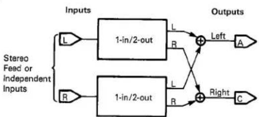
Fig. 2.8. Block Diagram, Dual Mono Input/Stereo Output.
flowchart
graph LR
    A["Input L"] --> B["1-in/2-out"]
    C["Input R"] --> D["1-in/2-out"]
    B --> E["+"]
    D --> F["+"]
    E --> G["Left"]
    F --> H["Right"]
    G --> I["A"]
    H --> J["C"]
    style A fill:#f9f,stroke:#333
    style C fill:#f9f,stroke:#333
    style B fill:#ccf,stroke:#333
    style D fill:#ccf,stroke:#333
    style E fill:#cff,stroke:#333
    style F fill:#cff,stroke:#333
    style G fill:#ffc,stroke:#333
    style H fill:#ffc,stroke:#333
    style I fill:#cfc,stroke:#333
Possible Input/Output Configurations. The stereo input/stereo output configuration shown in Fig. 2.6 is the most commonly used.
Both the Chamber program and the Multiband Delay program use a mono input/stereo output configuration. In these programs, the two inputs are internally bridged to form a composite signal that is then processed into a synthesized stereo output (see Fig. 2.7).
The Chorus & Echo program and the Resonant Chords program use a dual mono input/stereo output configuration in which each of the two inputs is treated as an independent mono source that is then processed into a synthesized stereo output. As shown in Fig. 2.8, these stereo pairs (one from each output) are then combined into a single stereo pair (both right-channel stereo image routed to Output C and both left-channel stereo images routed to Output A).
The Split programs employ a configuration that uses separate synthesized stereo pairs for each input (Left input = Outputs A and C, and Right input = Outputs B and D) (see Fig. 2.9). This configuration is known as dual mono input/dual stereo output.

Fig. 2.9. Block Diagram, Dual Mono Input/Dual Stereo Output — Split Processing.

flowchart
graph LR
    L["Inputs"] --> A["1-in/2-out"]
    R["Inputs"] --> B["1-in/2-out"]
    A --> A1["A"]
    A --> A2["C"]
    B --> B1["B"]
    B --> B2["D"]
    A1 --> Left1["Left"]
    A2 --> Right1["Right"]
    R --> R1["R"]
    R1 --> R2["R"]
Note: For dual-mono input configurations, "Left" and "Right" inputs refer to two independent signal sources, with one source using the left input jack and the other using the right. Each of the two inputs is treated as a mono signal source with no relation to left and right imaging in a stereo field.
Although all programs, except the mono-input programs just mentioned, usually operate in a stereo input/stereo output configuration (basic hookup), any of the programs (except the Constant-Density Plate A program) can be used in a mono input/stereo output configuration by bridging the two inputs or sending the same mix to each (see Fig. 2.10). This configuration is particularly useful when creating a stereo effect from a mono signal. If the application requires a mono result, the main outputs can be summed together, or, if no mixer is available, using only one of the outputs produces acceptable results. (For two distinct mono outputs on Split programs, sum Outputs A and C as one output and B and D as the other.)

Fig. 2.10. Block Diagram, Bridged Mono Input/Summed Mono Output.

flowchart
graph LR
    A["Mono Input"] --> B["Inputs"]
    B --> C["L"]
    B --> D["R"]
    C --> E["2-in/2-out"]
    D --> E
    E --> F["Left"]
    E --> G["Right"]
    F --> H["A"]
    G --> I["C"]
    H --> J["+"]
    I --> J
    J --> K["Mono Output"]
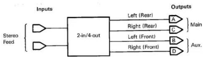
The Concert Hall, Bright Hall, and Room programs make effective use of quadraphonic patching (see Fig. 2.11). Although these two programs are stereo, they also provide true four-channel output. To employ quad processing, use the two main outputs (A and C) to feed corresponding left and right rear chan-
nels, and use use the two auxiliary outputs (B and D) to feed the corresponding left and right front channels. Note that for nonquad processing, outputs B and D can be added into a stereo or mono mix for increased density.
Fig. 2.11. Block Diagram, Stereo Input/Quad Output.

flowchart
graph LR
    A["Stereo Feed"] --> B["2-in/4-out"]
    B --> C["Left (Rear)"]
    B --> D["Right (Rear)"]
    B --> E["Left (Front)"]
    B --> F["Right (Front)"]
    C --> G["A"]
    D --> H["C"]
    E --> I["B"]
    F --> J["D"]
    G --> K["Main"]
    H --> K
    I --> L["Aux."]
    J --> M["DAux."]
Installation
Level Adjustments
The input and output levels for the 224X are factory set for unity gain with a maximum output level of +12 dBm. The maximum input levels range from +8 to +18 dBm, and maximum output levels range from slightly less than +8 dBm to slightly greater than +18 dBm. Input and output levels can be adjusted using a small flat blade screwdriver inserted into access holes on the front panel of the mainframe.
Input Levels. The 224X has two delay-line diagnostic programs (Zero Delay and 0.5-second Delay) for adjusting input levels. To adjust input levels, turn on the 224X by pressing the POWER pushbutton on the front panel. Wait for the power-up diagnostics to complete (about 25 seconds), press PAGE, and while holding it down simultaneously press PROG; release the PAGE and PROG keys, wait for the display to stop and press REG; wait for the display to stop, and press numeric-select key 7 (for Zero Delay) or 8 (for 0.5-second Delay).
Caution: While the delay-line diagnostic programs are operating, do not press any other numeric-select keys except 7 or 8.
The LARC's upper display window will read:
7 ZERO DELAY (or 8 .5S DELAY)
" PROG" = EXIT
If the display reads differently, press the RESET switch on the mainframe's front panel and repeat the procedure. (If the display still does not read properly, refer to Sec. 6 in this manual.)
Caution: After pressing RESET, do not press any of the numeric-select keys until the 224X resumes normal operation — pressing a numeric select key could erase the user memory registers.
Next, feed a musical source or 1-kHz test tone at the maximum peak level that you use in your system into each input channel (Right and Left) of the 224X. Using a screwdriver inserted into the INPUT LEVEL screwdriver pots on the mainframe's front panel, set input levels so that the peak input amplitude falls just short of illuminating the +12 dB LEDs (for Right and Left inputs) on the right side of the LARC's top display window.
Warning: Do not overdrive the 224X — its clipping characteristic, like that of other digital audio equipment, is very abrupt.
When the input levels are satisfactory, press PROG twice to exit the delay-line program and return to normal operation (the 224X runs its power-up diagnostics before returning to normal operation).
Output Levels. To set the peak output levels from the 224X, access the delay-line program.
When using this program to set output levels, the Left input channel is passed to Outputs A and D and the Right input channel is passed to Outputs C and B. Using a screwdriver inserted into the OUTPUT LEVEL screwdriver pots on the mainframe's front panel, set levels appropriate to your application and other equipment.
When output levels are set, press PROG twice to return to normal operation.
Do not use other 224X programs to set output levels — normally, the output levels differ significantly when tested. To check output levels while using other programs, use program material or a noise source, do not use a pure tone.
2.4
Location of Controls, Indicators, and Connectors
LARC front view
Main display
shows names and values for all selections
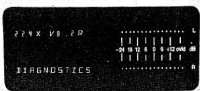
Headroom indicator (ppm response)
+12 dB indicates clipping; ovid indicates analog or digital clipping. Proper input level is with both the +12 dB and ovid LEDs unlit
Program-select and register-select keys
PROG selects programs when used with numeric-select keys
REG selects registers when used with numeric-select keys


Numeric-select keypad (1 to 0)
Main operating keys
BANK scrolls through available program or register banks
VAR displays running program and variation when pressed once; steps through and activates program variations when pressed twice or more
Slider display line
shows abbreviated names of active variable parameters on current control page controlled by corresponding sliders

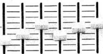
Parameter-control sliders
adjust variable parameter values on current control page
natural_image
Pure electrical circuit lines without any symbolsSTO stores user-modified parameter settings in registers (when used in conjunction with REG key)
PARAM accesses Parameter toggles
TAPE allows storage, recall, or verification for loading register banks onto audio cassette tape
MUTE outputs mute—active only while depressed (not for use on CD Plates and Splits)
2nd F allows extra functions when depressed before the following keys: BANK allows labeling of register banks
REG allows labeling of registers STO clears registers when used in conjunction with REG key
PAGE ignores control page presets and activates all sliders on a current page
PAGE steps through active control pages
Slider display-select keys
show parameter values in main display for corresponding sliders

Installation
LARC Rear View


224X Mainframe front view

Reset switch
push and release
momentary switch
initiates system
reset
push-on, push-off mains switch
indicator lamp
level adjustment
access holes
Input level adjustment access holes
Power-on switch
Power-on
A, B, C, D Output
Left and Right

224X Mainframe
Rear view

Operation
3.1
Introduction—The Basic Concept
The 224X is a sophisticated signal processor, in both its capabilities and control functions. It is much more versatile than other reverberation devices, and the LARC increases its ease of use even further by offering an interactive, prompting interface. A system of banks, programs and variations, control pages, and registers makes this versatility immediately available, even to inexperienced users. You will find the LARC a powerful and exciting addition to the 224X, and if you are a new 224X user, you will find the LARC an informative, self-prompting interface into the world of digital reverberation. Whether or not you are familiar with the 224X, please read this section to understand how to operate the LARC and 224X.
The 224X digitizes incoming signals and processes the digitized signals; it then reconverts the processed signals into analog for output. Because the modifications to the sound are totally under the control of the 224X's high-speed processor, which is directed by the LARC and its software, the range of sound is extremely wide. The 224X has the ability to emulate the response of many different kinds of actual spaces, mimic other artificial reverberation devices, and create complex effects with minimal controls. In addition, the Split programs allow the 224X to serve as two separate reverb devices.
3.2
Banks, Programs, Pages, and Variations
3.2.1 How To Load Programs
The 224X with LARC stores its reverberation programs in banks. A bank is a convenient grouping of similar, but unique, programs comprising sets of instructions that direct the 224X's high-speed processor to emulate acoustical spaces, special effects, or both. Each program defines a set of variable parameters that uniquely characterize the program.
For convenience, all banks and programs have names, and all programs have at least one preprogrammed variation—groupings of preset parameters. Changing parameters is accomplished through control pages, which are arrangements of variable parameters whose values can be changed by moving the LARC's sliders—most programs have four control pages, and each page holds as many as six variable parameters (corresponding to the LARC's six sliders).
By pressing combinations of the LARC's upper rows of labeled pushbuttons, you can access the banks, programs, variations, and control pages. (You are automatically placed in page 1 of variation 1 when you access a program.) When in a variation, you can alter parameter settings using the LARC's sliders, tailoring each variation to suit your taste and applica-
tion. If you wish to save your settings for future use, you can store them in one of 36 memory registers. If power is interrupted or the unit is reset, the 224X brings up the last active bank, program, and variation, including all the settings then in effect.
In general, any variation within a given program can be generated from any other variation simply by changing the operating parameters with the control sliders. One of the best ways to get acquainted with the 224X is to store a variation in a register, then call another variation of the same program and modify it until it sounds exactly like the first one. As long as the two variations come from the same program, this procedure can always be performed.
The LARC allows the greatest flexibility of control over the 224X. It can be used to scroll through (without loading) possible banks and programs by stepping through menus, or it can serve as a command console to load a desired program, variation, or register instantly. The LARC's upper display window guides you through these operations.
Operation
To load programs:
■
from the current bank: press PROG, N (where N is one of the numeric-select keys from 1 to 0)
-
from a different or another bank: press BANK, N, PROG, N.
Note: The BANK and PROG keys can scroll through their respective contents (displaying titles only) without loading programs; for example:
■
BANK, BANK, BANK scrolls through three banks
■
BANK, 3, PROG, PROG scrolls to the second program in bank 3.
Note: Once PROG has been pressed, the numeric-select keys can be used to load any of the programs in a given bank.
Remember that a program will run only when pressed in conjunction with a numeric-select key; for example:
B
BANK, 2, PROG displays the name of bank 2 program 1; to run this program, press the numeric-select key 1.
When a program is active, a banner telling you what bank, program, and variation are running appears in the bottom right of the LARC's upper display. The banner looks like this:
B5 P4 V1
At any time, you can display this banner by pressing VAR once, or one of the keys under the sliders; after pressing a slider key, the slider's value is displayed and after a few seconds, the banner appears.
To access variations within a program:
■
press VAR, VAR, ... VAR, which sequentially steps through all available variations (unlike the BANK and PROG keys, VAR activates the variations in sequence)
or
-
press VAR, N, which selects variation N.
Note: Once VAR has been pressed, the numeric-select keys can be used to activate any of the variations. Pressing N, N, ... N changes to other variations.
When you become familiar with the system of banks, programs, and variations, shuttling between them is easy; for example:
To load bank 3 program 2 variation 4:
-
press BANK, 3 (or successively press BANK until BANK 3 appears in the LARC's upper window)
■
next press PROG, 2 then VAR, 4 (or successively press VAR four times).
3.2.2 How To Modify Programs
After loading a program, you can adjust and modify its variable parameters by moving the LARC's sliders. Sliders are grouped in convenient control pages; to access these control pages:
■
press PAGE, N or PAGE, PAGE, ... PAGE, which successively steps through each control page.
When a new program, variation, or control page is selected, the sliders are deactivated (the display does not change) until they are moved through their preset values. When
changes have been made on a page, and a new page is activated, those previous changes remain intact and disappear only when another variation or program is loaded. Because all variations have preset values (remember that you are automatically placed in page 1 of variation 1 when you load a program), you must first move a slider through its preset value to activate it. (You can activate all sliders on a given page without passing their preset values by pressing 2nd F, PAGE.) Anytime a slider is moved, it displays its values in the LARC's upper window while it is
being moved. Sliders can be adjusted in real time—tuning a desired reverberation or special effect.
Note that abbreviated codes appear in the display window above active sliders. These codes indicate the parameters that the sliders are controlling. To receive a more descriptive title for each parameter, press the keys directly
below each slider. This procedure displays the full parameter title and its current value in the LARC's upper window. Also, this display appears whenever a slider is moved.
Section 3.3 describes in greater detail how the variable parameters alter the programs.
3.2.3 How To Store and Recall Modified Programs
Once satisfied with your modified settings, you can store them in one of the 224X's 36 memory registers. The registers are organized into banks that can be loaded on tape via the LARC for storage.
Register Storage. The 36 registers can be divided among 10 possible banks; each bank can hold as many as 10 registers.
To access register banks, press REG. You can now scroll through available register banks by pressing BANK, BANK, ... BANK or press BANK, N to access a particular bank.
To exit from the register menu and return to the program menu,
press VAR.
Once you have reached the desired bank, you can scroll through the registers in the bank by pressing REG, REG, ... REG. (Pressing REG, N loads a register that has been previously stored.)
To store modified parameter settings in a register, once you have scrolled to the appropriate bank and register
press STO and while you hold it down the display will read:
STORE BX RY
where X and Y are the numbers of the last scrolled bank and register, respectively.
The register is stored when you press REG while still holding down STO, and the LARC displays the derivative program on the top line. The bank and register numbers of the
stored settings are displayed on the bottom line, and the derivative bank and program appear in brackets. For example:
CONCERT HALL
B3 R5 [B1 P1]
This example signifies that a derivative of the Concert Hall program (bank 1 program 1) is now stored in register bank 3 register 5. Remember that when you store settings in a register, the previous contents of the register are erased. Note that until a stored register is labeled by a user, it is automatically called --; these hyphens indicate spaces available for labeling, the procedure for which is discussed in Sec. 3.2.4.
To from exit a running register and return to programs
■ press PROG, N.
To clear a register
press 2nd F, STO and while holding down STO, press REG.
When a register has been cleared, it is relabeled EMPTY.
Note that when all 36 registers are used, attempting to store another register results in the message:
NO ROOM LEFT
IN REGISTERS
Operation
Register Recall. Once registers have been stored, they can be recalled and activated by scrolling to the appropriate register bank and pressing REG, N. Once in the register mode, various registers in the same bank can be accessed by pressing N, N, ... N.
3.2.4 How To Label Banks and Registers
To label a register bank

scroll to the bank you wish to label

press 2nd F, BANK.
The display will read:
ENTER LABEL
FOR BANK X
where X is the number of the bank being labeled.
All six sliders can now be used to label bank X. (42 characters including a space are available on each slider.) Once the desired label is obtained, press BANK to store it. A bank retains its user label until changed using this procedure, even if all registers in the bank are empty.
To label a register

scroll to the register you wish to label

press 2nd F, REG.
The display will read:
ENTER LABEL
FOR REG X
where X is the number of the register being labeled.
The first five sliders can be used to label the register. Once the desired label is obtained, press REG to store it. A register is automatically relabeled EMPTY when it is cleared and cannot be relabeled until something is again stored in it.
3.2.5 Tape Storage and Recall
Equipment Required. To store register banks on audio tape, use the following equipment:
high-quality audio tape recorder (cassette, microcassette, or reel to reel) with earphone, external speaker, or line-level output jack and an auxiliary or line-level input jack—a microphone input is suitable, providing an appropriate attenuator is placed between the input plug and jack
Lexicon cassette interface cable (Lexicon no. 680-03690) with a male 5-pin 180° DIN connector terminating in two miniphone plugs (cable also available from Radio Shack cat. no. 26-1207), supplied with the LARC
high-quality audio tape (such as TDK or Maxell); if cassettes are used, avoid tapes longer than 60 minutes per side.
Note: The tape recorder/playback unit must provide good performance and accurate head-to-tape contact, tape alignment, and speed to ensure interchangeability between different tape decks. During recording, use the Automatic Level Control (ALC or AUTO) or set the VU meter to 0 if using a manual control. (For cueing and level settings, the LARC inserts a 15-second 4800-Hz tone leader before and a 3-second trailer tone after each entire data transmittal. The 15-second leader is made up of 3 seconds of pure tone and 12 seconds of pure tone with intermittent clicks.)
If the playback unit is equipped with a tone control, adjust it for reduced high-frequency response to prevent ringing in the playback signal. The nominal tape record output from the LARC is +4 dBm (equivalent voltage into 600 ohms), and the tape playback level to the LARC can be between 0 and +8 dBm. Adjust the playback output level to +4 dBm (or adjust for reliable operation if monitoring is not convenient). With good tape and players, playback level should not be critical.
Connections. Connect the male 5-pin DIN plug on the Lexicon cassette interface cable into the LARC's rear panel. Connect the black miniphone plug into the tape recorder's earphone, external speaker, or line-level output jack, and connect the gray miniphone plug into the auxiliary or line-level input jack (a microphone input can be used with suitable attenuation).
Note: Check all connections before storing data.
Tape Storage. Once the appropriate connections have been made, ready the tape deck by (1) loading and cueing the tape, (2) switching (if possible) the input level control to AUTO, and (3) adjusting the tone or treble control to low or minimum. (If the input level cannot be set to AUTO, set the VU meter to 0 during the first 15-second leader tone just before data are transferred to tape.)
To store a register bank or banks:
■ press TAPE three times to select the prompt:
STORE BANKS
ON TAPE
■ select the bank (or banks) you wish to store by pressing the corresponding numeric-select key or keys in the order you wish to store them—the numbers selected appear in the bottom left of the display. The register banks are recorded onto the tape in the order chosen. Be sure to enter the same banks in the same order that they were stored in.
Start the tape deck in record mode.
■ press TAPE to commence output of data to tape.
(If you wait longer than 45 seconds, the LARC returns to the last active program and cancels the storage process. To cancel the process at any time, press VAR.)
In the lower right of the display, a status indicator flashes during the storage process; note that the LARC inserts a 15-second leader at the beginning and a 3-second leader at the end of the complete data transfer.
When the transfer is complete, the display will read:
TAPE STORE
COMPLETED
After a tape transfer is complete, always verify that the data stored are accurate.
Tape Verification. Verify that all data stored are complete with the following procedure:
■ press TAPE.
The display will read:
VERIFY BANKS
AGAINST TAPE
press the appropriate numeric-select key or keys for the banks you wish to verify (in the same order in which they were stored).
Cue the tape to the beginning of the segment you wish to verify.
■ press TAPE.
Start the tape in playback mode. Once the verification is complete, the display will read:
VERIFY GOOD
000SE 000HE
or
VERIFY BAD
002SE 001HE
Operation
The bottom line indicates soft (correctable) and hard (uncorrectable) errors that have occurred during the transfer. Soft errors (SE) do not affect the data and are displayed for diagnostics only. Hard errors (HE) indicate problems with the transfer that require repeating the process. (The example shows 2 soft and 1 hard error.) In these cases, try the verification procedure again. If it is still bad, re-store the register banks and repeat the verification procedure.
Note: Continued occurrence of soft errors could indicate a deficiency in the system—possibly an inferior tape deck or tape, improper record or playback levels, or excessive high-frequency response.
When the storage is verified, press VAR.
Tape Recall. To recall register banks from tape storage, use the following procedure:
■ press TAPE twice.
The display will read:
RECALL BANKS
FROM TAPES
press the numeric-select keys of the banks you wish to fill (the banks stored on tape are recalled in the order in which they were stored —their previous numbers are not carried over).
Cue the tape to the beginning leader of the segment you wish to recall.
press TAPE.
Start the tape recorder in playback mode. When the recall is complete, the display will read:
RECALL GOOD
000SE 000HE
or something like
RECALL BAD
004SE 001HE
As with tape verification, the bottom line indicates errors that may have occurred during the process. Soft errors do not affect the recall, but hard errors indicate that the information stored in the LARC's register banks does not coincide with the information stored on the tape. Check the playback volume and tone control on the tape deck, and repeat the recall.
The LARC recalls for storage as many registers as space allows. If the total is more than 36 registers, the LARC fills up the last available register until the limit of 36 registers is reached.
Note: To ensure safekeeping, store important data twice on tape and, if possible, record a backup tape.
How The Controls Affect The Sound
This section discusses the functions of the main reverberation parameters that are stored in the 224X. Those parameters that apply to the Effects programs are discussed in detail under their specific programs in Sec. 4.
Table 3.1 briefly lists and describes all variable parameters and toggles including those applicable to the Effects programs.
| Table 3.1. Control Parameters. | Parameter | Description |
| Reverberation Parameters | ||
| Attack | Sets the explosiveness or sharpness of the initial response to an input. (On Plate and Chamber programs only.) | |
| Chorus | Modulates the delays in reverberation programs or the Chorus & Echo program. Can introduce more fullness to sound, create the illusion of added voices, or produce flanging and pitch-twisting effects. | |
| Crossover | Controls the frequency at which a transition from low-frequency reverb time to mid-frequency reverb time takes place. | |
| Decay Optimization | A parameter toggle that activates and deactivates a subroutine that automatically optimizes decay parameters for various source levels and material. | |
| Definition | Controls the echo density in the latter part of the sonic decay. | |
| Depth | Controls the illusion of position within an acoustic environment. (On Hall and Room programs only.) | |
| Diffusion | Controls the degree to which echo density increases over time. | |
| Dynamic Decay | A parameter toggle that activates and deactivates the LF and Mid Stop Decay controls. | |
| Fine Predelay | Finely adjusts the predelay values independently in each of two stereo channels. | |
| Gate | Sets a time delay in switching from running decay to stopped decay (when using the dynamic decay feature). Used for gated reverb effects. | |
| HF Bandwith | Sets the corner frequency of a 6-dB/octave low-pass filter that affects all sound from the 224X. | |
| LF Decay | Sets the reverberation time of low-frequency signals. | |
| LF Stop Decay | Sets the decay time of low-frequency signals in the absence of input. | |
| Mid Decay | Sets the reverberation time of mid-frequency signals. | |
| Mid Stop Decay | Sets the decay time of mid-frequency signals in the absence of input. | |
| Mode Enhancement | A parameter toggle that activates and deactivates the Chorus control. | |
| Predelay | Sets the time from an input to the onset of reverberation. | |
Operation
| Table 3.1. Control Parameters cont'd. | Parameter | Description |
| Reverberation Parameters (Continued) | ||
| Preecho Delay | Sets the delay time of the early echoes. | |
| Preecho Level | Controls the level of the early echoes. | |
| Size | Sets the apparent size of the acoustical space produced by the 224XL (essentially the longest dimension in meters). | |
| Slope | Controls the decay characteristics of the Inverse Room program. | |
| Treble Decay | Sets the frequency above which sounds decay at a progres-sively faster rate. | |
| Effects Parameters | ||
| Band Delay | Sets the delay time for each frequency band in the Multiband Delay program. | |
| Band Level | Controls the relative level of each frequency band in the Multi-band Delay program. | |
| Crossfeed | Controls the level and balance of a feedback mix routed back into the Left and Right input channels in the Resonant Chords program. | |
| Feedback | Controls the level and polarity of signals recirculated back into the delay line in the Chorus & Echo program (and two delays in the Multiband Delay program). | |
| HF Cutoff | Sets the high-frequency cutoff of a low-pass filter (6 dB/ octave). | |
| LF Cutoff | Sets the low-frequency cutoff of a high-pass filter (6 dB/ octave). | |
| Note Level | Sets the level of the notes in the Resonant Chords program. | |
| Note Pitch | Tunes each note in the Resonant Chords program to a desired pitch. | |
| Note Predelay | Sets the time from an input to the onset of a note in the Resonant Chords program. | |
| Pan | Places the sound of the separate channels along a left-to-right continuum within a stereo field. (Resonant Chords, Multiband Delay, and Chorus programs.) | |
| Resonance | Regulates the amount and polarity of feedback to the individual delay lines in the Resonant Chords program. | |
| Voice Delay | Controls the delay time of each of the "voices" or delay taps in the Chorus and Echo program. | |
| Voice Level | Sets the level of each of the "voices" or delay taps in the Chorus and Echo program. | |
3.3.1 Variable Reverberation Parameters
Decay Time vs. Frequency: LF and Mid Decay, Treble Decay, and Crossover.
Reverberation is usually greatest right after an input, and then it decays approximately linearly down to zero. The time required for reverberation to decay 60 dB from its peak value is referred to as RT60. The overall reverberation time and the ratio of reverb to original sound (set by the mixing console) determines whether a sound is wet (reverberant) or dry (acoustically dead). Decay times for normal reverberation range from a fraction of a second to several seconds. In addition to duplicating a wide variety of natural reverberation phenomena, the 224X can extend decay times far beyond the realm of natural phenomena to produce a range of interesting effects.
Under natural acoustic conditions, different portions of the audio spectrum decay at varying rates, so that the tone of the reverberation actually changes over time. The 224X provides extensive control over the tone of reverberation, allowing decay time to be set in relation to frequency. In the reverberation programs, the LF and Mid Decay sliders control decay time (expressed in RT 60) of the low and middle portions of the frequency spectrum, respectively. The Crossover slider adjusts the point in the frequency spectrum in which the LF Decay slider relinquishes control and the Mid Decay slider assumes control. The Treble Decay slider adjusts the point in the frequency spectrum above which the frequencies fade away at a much faster rate than the lower frequencies. The Treble Decay slider, therefore, sets the frequency above which decay time becomes progressively shorter.
Choice of decay time depends on material and desired ambiences or effects. Shorter decay times maintain articulation and impart an "up close" ambience to the sound. As decay times are lengthened, the sound begins to take on more of a texture of "lushness." Decay times affect different sounds in different ways.
Classical or symphonic music is typically produced in environments having decay times from 1.8 to 2.5 seconds, whereas organ music or religious music produced in a church have typical decay times of several seconds.
Although this reverberation sounds normal for organ or religious music, if a vocal in popular
music were to have the same decay characteristics, it would sound exceptionally rich.
As an example of how these controls are used together to create different ambiences, in the Concert Hall program, a really high-quality concert hall can be created by setting LF Decay between 2.5 and 3.0 seconds, Mid Decay between 1.8 and 2.5 seconds, and Crossover between 600 and 800 Hz (as in variation 1). A typically poor concert hall sound can be obtained by setting LF Decay to 1 second, Mid Decay between 1.5 and 3.0 seconds, and Crossover to 1000 Hz. The lack of low frequencies in relation to the mid frequencies in the decay of the poor concert hall makes the sound seem thin, without body or warmth—reminiscent of modern concert halls whose reflecting surfaces are light-panelled, thinly constructed walls.
To duplicate the natural phenomenon of air absorption of high frequencies, the Treble Decay control should always be set between 6 and 10 kHz. For the previous examples, 6 kHz should provide the most natural setting.
For special effects, and for rock and other types of popular music, experimentation with different settings of these controls in a variety of combinations can lead to finding a special ambience, effect, or sonic shading for a specific application. In multitrack recording, it is not uncommon to create a different ambience for each track or instrument/vocal section to lend a distinct color to each for a rich, varied sonic impression. The Split programs in the 224X are particularly convenient for this application because they allow two totally distinct sounds to be used on different tracks simultaneously without rerecording.
Dynamic Decay: LF and Mid Stop Decay. In addition to the regular decay characteristics set up by the LF and Mid Decay, Treble Decay, and Crossover controls, decay characteristics that apply only to the end (tail) of a sound can be set up using the LF and Mid Stop Decay controls. These controls are analogous to the LF and Mid Decay sliders, except that they are activated by the Dynamic Decay toggle and they affect reverberation only after the input sound has stopped.
Operation
When the Dynamic Decay toggle is turned on, the LF and Mid Stop Decay sliders can set the amount of reverberation in the respective bands DURING PAUSES BETWEEN SIGNALS INPUT INTO THE 224X. The regular LF and Mid Decay sliders set the decay when input is present. If running decay is short and stopped decay is long, the sound will have crisp, clean, well-articulated and defined attacks with long, flowing echo tails.
Appropriate source material is highly critical in achieving this effect. Lead vocals or instrumental solos with a somewhat continuous flow and distinct breaks between phrases are ideal. These materials enable each phrase to be cleanly articulated, while providing echo trails at the ends of the phrases for a defined but "fat," "wet" sound. A full ensemble mix will usually swamp out the dynamic effect because phrase endings in individual lines are masked by the continuing sound of other lines. Choppy input material may also produce inappropriate results because the brief pauses within a particular passage can be mistakenly interpreted as phrase endings.
If stopped reverb decay is less than running reverb decay, the effect is reversed. Phrases in backup material can be placed in pools of reverberation, yet be cleared out of the way of new phrases in lead material. The results can be very startling! With percussion, this feature can be used to "gate" the reverb, so that a drum hit could result in an enormously fat sound of short duration to maintain the tight, percussive quality of the drum.
Predelay. Predelay is the amount of time that elapses from an input to the onset of actual reverberation. Under natural conditions, the amount of predelay is a function of the size of the acoustic space and the relative positions of the sound source and listener(s). The Predelay slider on the 224X duplicates this phenomenon and is used to create a sense of distance and volume within an acoustic space. A long predelay places the reverberant field BEHIND rather than on top of the input. Many of the 224X programs have a lower limit on the amount of predelay determined by the size of the acoustic space being represented. Some programs have Fine Predelay controls for the left and right channels that adjust the relative time of the first reflections; these can be used to fine tune the stereo image of the reverberation image.
A sense of continuity between source and reverb is maintained up to around 40 milliseconds of predelay, after which sound begins to break up into distinct "slap" echoes; however, large values of predelay effectively give the impression of large size if early reflections (pre-echoes) are used to fill in the spaces between the input and the delayed reverberation.
Depth. The Depth slider (on the Halls and Rooms programs) controls the illusion of position within the reverberant field. Visualize a concert hall. If a listener is seated in the first row in the concert hall, the reverberant sound is primarily reflections from the front wall (stage back), with few reflections from the side walls and even fewer reflections from the rear.
As the listener moves farther and farther back, the proportions of the different reflections change. The Depth control helps create the illusion of different positions within an acoustical environment. When the Depth slider is fully lowered, the reverberation output is composed almost entirely of early reflections, representing a position close to the stage. As the control is raised, greater proportions of side and rear wall reflections are heard, representing positions farther to the rear of the concert hall, until the reverberation output is composed almost entirely of rear wall reflections.
Attack. This control (on the Chamber and Plate programs) sets the level of the initial sonic pulse (attack). Attack affects the level of sound within the first 50 milliseconds only; high settings cause an explosive sound, and low settings cause the sound to build up more slowly with time.
Chorus. Advancing the Chorus control makes reverberation sound less metallic by randomizing delay times in the reverberation programs. This control is normally active, but can be turned off with the Mode Enhancement toggle. Raising or lowering the Chorus control varies the rate of modulation. Because the control causes pitch variation, sources with very little pitch wobble, such as guitar or piano, should have chorus values at or below 50; vocals can use 50 to 60; and spoken voice up to 70. A good practice is to raise the slider until pitch wobble becomes noticeable, then lower it slightly. Although the effect of the Chorus control is quite different for the reverberation
programs and the Chorus and Echo program, the principle is the same (for more detail, see Sec. 4.4.1).
HF Bandwidth. This control sets the frequency above which a low-pass filter attenuates all tones by 6 dB per octave. This attenuation occurs at the input of the reverberation algorithm and affects the preeches as well as the reverberant sound. This control does not affect the rate at which high frequencies decay, which is determined by the Treble Decay slider.
Diffusion. To understand Diffusion, consider the output of the 224X in response to the input of a single click. After a delay time set by the Predelay slider, the single-pulse input produces multiple pulses in the output, decreasing in amplitude and increasing in density with time. Thus, when a click is reverberated, one first hears a few relatively discrete reflections that soon blend into a smooth swish. Diffusion refers to the degree to which the density of echoes increases. This parameter is affected by program selection and is controlled by the Diffusion slider.
The Diffusion slider sets the amount of initial buildup in density. High settings of Diffusion result in high initial buildup, and low settings cause low initial buildup. After the initial period controlled by the Diffusion slider, density continues to rise at a rate determined by the program. For example, in the Concert Hall program, the density starts building at a slow rate, but then rapidly increases. In the Constant-Density Plate A program, the density remains constant after the initial buildup period, and in the Rich Chamber program, there is a slow, continual buildup after the initial buildup set by the Diffusion slider.
Much of the difference between programs is because of the different rates at which density increases. The Hall, Plate, and Room programs use a rapid increase in density with time, so even when Diffusion is set low, after a time (approximately 300 milliseconds for the Hall and Plate programs, 150 milliseconds for the Room program, and 70 milliseconds for the Small Room program), the density is great enough that individual echoes cannot be distinguished. In contrast, the Constant-Density Plate programs maintain a constant density after the initial buildup determined by the Diffusion control. If Diffusion is set too low in this program the reverberation has a noticeably grainy quality that does not smooth out as the sound decays. Density in the Rich Chamber program increases with time, but at a much lower rate than that of the Hall or Plate programs, and this low rate of increase gives this program less "color" as the sound decays. Low diffusion is good for vocals, and high diffusion is good for percussion.
Definition. This control affects the rate of increase in density in the latter part of the sonic decay. In the lowest position of the slider, the rate is that determined by the program; raising the slider decreases the rate. Raising Definition causes the sound to become choppier as the decrease in density of the echoes creates increasingly distinct repetitive echo trails rather than a smooth, continuous fusion of sound.
Preecho. Preechoes can best be understood by visualizing a stage environment, where the early reflections or preechoes are the sounds emanating from the rear and side stage walls directly after sound from the stage. Usually, the rear stage wall echo is earlier and louder than those from the two side walls.
The Preecho controls on the 224X change the perceived reflecting surfaces surrounding the source. Most programs in the 224X have four or more discrete preechoes, half panned left and half panned right. Each represents a reflecting surface and can be adjusted in level and time of delay using the respective sliders.
Changing amplitudes and delays of the pre-echoes changes the apparent geometrical arrangement of the acoustic environment. For example, to use Preecho controls to create an image of a rear wall, adjust the first two sliders to roughly the same delay time and amplitude. This keeps the images in the reflections panned as they were in the input to the 224X. If one of the two sliders is set earlier than the other by more than 2 milliseconds, the image tends to shift to that channel. If the difference in delay gets larger than a few milliseconds, the original panning of the source is lost, and the reverberation appears more spacious. (Delay differences of 2 milliseconds or so can cause problems when the reverberation is mixed to mono and have been avoided in most of the 224X program variations.)
Operation
The second pair of channels can be used to simulate side walls or the ceiling. These typically have lower amplitude and longer delays than the first pair of channels, and differences in their delays are less striking.
A stereo pair representing a rear stage wall could be set at a level of 30 with delay times between 20 to 30 milliseconds. By slightly varying the delay time between one channel and the other, a greater sense of space and dimension can be created. The preechoes from the side walls could be simulated by setting the delay times of a second stereo pair between 40 and 50 milliseconds with a greater offset between the two than the first pair. The level of this second pair would be set lower than the first pair.
A highly effective application of the pre-echoes is to fill in the space between the in-
itial sonic impulse and the delayed reverberation when a large value of predelay is used. The Rich Chamber program introduces diffusion to the preechoes, which makes them less obvious when they are used to create a sense of large size. Note that only the Rich Chamber program has this feature.
Gate. The Gate slider selects the amount of time delay introduced in switching between a program's running and stopped decay time. This control is only active when the Dynamic Decay toggle is turned on.
Size. The size control allows continuous adjustment of the acoustical "space" created by the 224X. Size is available on most programs and is program dependent in range of adjustment. Note that large size setting will limit the available pre-delay on some programs.
3.3.2 Parameter Toggles
The 224X has three parameter toggles that are accessed by successive pushes of the LARC's PARAM key. Once a toggle has been accessed, it can be turned on by pressing 1 on the numeric-select keypad, or off by pressing 0. The state of the parameter toggle is displayed in brackets after the parameter name; for example:
DYN DECAY [1]
indicates that dynamic decay is turned on. Parameter toggle settings are stored in registers along with other parameter settings. Note that most variations have toggles preset to on.
Dynamic Decay. This toggle activates the LF Stop Decay and Mid Stop Decay sliders. For an explanation of the function of these sliders, see the previous section "Dynamic Decay: LF and Mid Frequency Stop Decay."
Mode Enhancement. This toggle activates the Chorus slider. For an explanation of the function of this slider, see the previous section "Chorus."
Decay Optimization. This toggle activates a software module that alters certain reverberation parameters in response to changes in input level. These changes make the decay of sound in the 224X less metallic and more natural. This switch is normally on. However, for certain kinds of source material (e.g., soft low-frequency tones from a synthesizer) audible clicks may occur during level changes. If audible clicks occur, turn off the Decay Optimization toggle. For the Constant-Density Plate programs, this toggle has no function.
Pages 4.4 and 4.5
Maximum SIZE for the Concert Hall and Bright Hall programs is shown as 87 meters. It should be 40 meters.
Page 4.33
Maximum SIZE for the Plate/Chorus program is shown as 80 meters. It should be 70 meters.
Lexicon Part #070-04902
Programs
| This section describes the reverberation and effects programs in the latest version of 224X software. The 224X's programs are organized into five banks:1Halls2Rooms3Plates4Effects5Splits | Sections 4.1 to 4.5 contain in-depth descriptions of the programs found in each bank, and Sec. 4.6 includes block diagrams of all programs.Each bank comprises a family of several programs that have similar characteristics. Table 4.1 lists the programs supplied with the current version of 224X software. |
Table 4.1. 224X Programs.
| Programs | Banks | ||||
| 1 Halls | 2 Rooms | 3 Plates | 4 Effects | 5 Splits | |
| 1 | Concert Hall7 Variations | Room4 Variations | Plate6 Variations | Chorus& Echo4 Variations | Hall/Hall1 Variation |
| 2 | Bright Hall5 Variations | Small Room4 Variations | Small Plate6 Variations | ResonantChords1 Variation | Plate/Plate2 Variations |
| 3 | Dark Hall7 Variations | Chamber1 Variation | ConstantDensityPlate A1 Variation | MultibandDelay1 Variation | Plate/Hall1 Variation |
| 4 | Rich Chamber8 Variations | ConstantDensityPlate B3 Variations | Plate/Chorus1 Variation | ||
| 5 | Dark Chamber8 Variations | Rich Plate8 Variations | Rich Split1 Variation | ||
| 6 | Inverse Room3 Variations | ||||
The Halls bank holds programs with a pronounced sense of large size and acoustic space. These programs lend space and ambience to recordings.
The Rooms bank holds the Room and Small Room programs, which also have a strong sense of space, but of smaller size than the Hall programs. The Room programs have a very wide range of uses in recording and broadcast. The Rooms bank also holds the Chamber programs, which have fewer size cues than the Halls.
The Plates bank holds programs that have high initial density and a smooth sizeless decay. These programs have a slight metallic tone and are widely used in mixing popular music.
In addition to reverberation programs, the 224X has several powerful special effects programs in the Effects bank that open up a whole new range of exciting possibilities traditionally provided only by other devices.
Programs
The Splits bank holds programs that allow the two input channels of the 224X to be processed independently, so entirely different reverberation sounds can be applied to different tracks in a mix.
Each program has one or more permanent variations. Each variation is a group of permanently set parameters that characterize the program for specific applications. Users can tailor these variations by changing the values of the parameters to suit their own applications and store the new parameter settings in registers for future use. Changing parameters is accomplished by accessing control pages, which are groupings of variable parameters whose values can be altered by moving the LARC's sliders. Most programs have four or five control pages, with each page holding as many as six variable parameters (corresponding to the LARC's six sliders). (Some pages have less than six variable parameters—for these cases, the unused sliders are inactive.)
In addition to the variable parameters, the 224X has three parameter toggles that are accessed through the PARAM key. The toggles are:
Dynamic Decay
Mode Enhancement
Decay Optimization.
All reverberation programs are preset with two parameter toggles on: Mode Enhancement and Decay Optimization (in the two . Constant-Density Plate programs, the Decay Optimization toggle is inactive).
Adjustable Preecho Delays are preset for all reverberation programs, but the Preecho Levels are preset (nonzero) on only some variations. For more detail, see the descriptions of individual programs following in this section.
4.1
Halls—Bank 1
The reverberation from the three Hall programs (Concert, Bright, and Dark) is designed to sound as if it goes BEHIND the direct sound, adding ambience but leaving the source unchanged. These programs have a relatively low initial echo density, which gradually builds as time progresses. These programs emulate real concert halls, which accounts for their clean initial sound. The Hall programs are especially good with classical music. On popular music, they can give separately recorded tracks the sense of belonging to the same performance by putting the whole mix in the context of a real-sounding acoustic space.
The Concert and Bright Hall programs have both stereo or quad outputs. For stereo operation, use Output A for left and C for right. For quad, assign Outputs A and C to the left and right rear channels and B and D to the left and right front channels, respectively. Note: For quad, the Depth slider affects Outputs A and C only and should be set low (from 0 to 10).
The Dark Hall program has stereo outputs: the left output is A and the right output is C.
4.1.1 Concert Hall—Program 1
Program 1, Concert Hall, was previously called the Main Hall (Program 1) in the 224. It emulates a concert hall about 120 feet long. The Treble Decay slider filters all the sound except the preechoes, giving a darker tone to the reverb than the Bright Hall program (program 2). This darker tone simulates
the effect of air absorption in a real hall and helps keep the ambience generated by the program from muddying the direct sound. Additional treble rolloff can be added by lowering the HF Bandwidth slider, which also darkens the Preecho Delays.
Variations in Concert Hall. The Concert Hall program has five control pages and seven variations. Table 4.2 lists the control pages and the variable parameters and their ranges. All variations have four adjustable Preecho Delays; variations 2, 4, and 6 have active Preechoes.
Variation 1 mimics a moderately large, reverberant hall. Average running reverb decay time is 2.6 seconds: LF Decay (3.0 seconds) is longer than Mid Decay (2.0 seconds). Diffusion is 25, and Depth is moderately low (33). Predelay is 24.0 milliseconds—the minimum for this program.
Variation 2 sounds especially good with classical music. It emulates a smaller hall sound than variation 1; both LF and Mid Decay are 1.7 seconds. Diffusion is lower (15) than in variation 1, and there are four Preechoes. Levels are preset to add a sense of stage reflections not present in a closely miked track.
Variation 3 has a very low Diffusion (01) that, along with its fairly long initial reverb decay time, produces an uncolored, natural quality on flute or voice. This variation works especially well when modified to produce very long reverb times; it is not for material containing strong transients. This variation was previously called Large Concert Hall (program 3) in the 224.
Variation 4 is a modification of variation 3 with a slightly longer Mid Decay (3.0 seconds), less HF Bandwidth (7.5 kHz instead of 9.0), longer Predelay (42.0 milliseconds), and four active Preechoes.
Variation 5 is just like variation 1, except that the average reverb decay time has been increased to 6.5 seconds.
Variation 6 is preset with the Dynamic Decay toggle on; average stopped reverb decay time (5.7 seconds) is longer than average running reverb decay (1.7 seconds), and it contains four preset Preecho Levels. This configuration creates a wash of reverb when the music or input source stops, but maintains clarity at other times.
Variation 7 is also preset with the Dynamic Decay toggle on, but with the variable reverb parameter values exactly opposite to those in variation 6; i.e., the average running decay time (5.7 seconds) is longer than the average stopped decay (1.7 seconds). The result is similar to what might be obtained if the output of a reverberation device were put through a gating circuit.
4.1.2 Bright Hall—Program 2
Program 2, Bright Hall, is similar to the Concert Hall program, except the Treble Decay slider affects the sound only after a few hundred milliseconds. The sound from this program is thus much brighter than that from the Concert Hall program, and many people prefer this brightness in popular music. Diffusion has also been set higher in all the variations, enhancing percussion sounds. If an even brighter sound is wanted, turn off the Mode Enhancement toggle.
Variations in Bright Hall. This program has five control pages and five variations. Table 4.3 lists the control pages and the variable parameter ranges. All variations have four adjustable preecho delays; variations 2 and 4 have active Preechoes.
For variations 1, 3, and 5, the HF Bandwidth control is preset to 19 kHz; for variation 2, it is 9.0 kHz; and for variation 4, 7.50 kHz.
Programs
Table 4.2. Concert Hall-Control Pages and Variable Parameters.
| Page | Variable Parameters and Ranges | |||||
| 1 | LF Decay | Mid Decay | Crossover | Treble Decay | Depth | Predelay |
| 70 sec | 70 sec | 19.0 kHz | 19.0 kHz | 99 | 216 msec | |
| 0.6 sec | 0.6 sec | 170 Hz | 170 Hz | 00 | 24.0 msec | |
| LF Stop Decay | Mid Stop Decay | Chorus | HF Bandwidth | Diffusion | Definition | |
| 2 | 70 sec | 70 sec | 97 | 19.0 kHz | 99 | 75 |
| 0.6 sec | 0.6 sec | 00 | 170 Hz | 00 | 00 | |
| Preecho Level 1 L>A | Preecho Level 2 R>C | Preecho Level 3 R>A | Preecho Level 4 L>C | |||
| 3 | 99 | 99 | 99 | 99 | Inactive | Inactive |
| 00 | 00 | 00 | 00 | |||
| Preecho Delay 1 L>A | Preecho Delay 2 R>C | Preecho Delay 3 R>A | Preecho Delay 4 L>C | Fine Predelay L> | Fine Predelay R> | |
| 4* | 188 msec | 188 msec | 188 msec | 188 msec | 31.3 msec | 31.3 msec |
| 0.00 msec | 0.00 msec | 0.00 msec | 0.00 msec | 0.00 msec | 0.00 msec | |
| Size | Gate | |||||
| 5 | 87 | 5.08 sec. | ||||
| 08 | 0.00 sec. | |||||
| 1 | 2 | 3 | 4 | 5 | 6 | |
| Sliders | ||||||
*The software for this page allows fine tuning.
Table 4.3. Bright Hall—Control Pages and Variable Parameters.
| Page | Variable Parameters and Ranges | |||||
| 1 | LF Decay | Mid Decay | Crossover | Treble Decay | Depth | Predelay |
| 70 sec | 70 sec | 19.0 kHz | 19.0 kHz | 99 | 216 msec | |
| 0.6 sec | 0.6 sec | 170 Hz | 170 Hz | 00 | 24.0 msec | |
| LF Stop Decay | Mid Stop Decay | Chorus | HF Bandwidth | Diffusion | Definition | |
| 2 | 70 sec | 70 sec | 97 | 19.0 kHz | 99 | 75 |
| 0.6 sec | 0.6 sec | 00 | 170 Hz | 00 | 00 | |
| Preecho Level 1 L>A | Preecho Level 2 R>C | Preecho Level 3 R>A | Preecho Level 4 L>C | |||
| 3 | 99 | 99 | 99 | 99 | Inactive | Inactive |
| 00 | 00 | 00 | 00 | |||
| Preecho Delay 1 L>A | Preecho Delay 2 R>C | Preecho Delay 3 R>A | Preecho Delay 4 L>C | Fine Predelay L> | Fine Predelay R> | |
| 4* | 188 msec | 188 msec | 188 msec | 188 msec | 31.3 msec | 31.3 msec |
| 0.00 msec | 0.00 msec | 0.00 msec | 0.00 msec | 0.00 msec | 0.00 msec | |
| Size | Gate | |||||
| 5 | 87 | 5.08 sec | ||||
| 08 meters | 0.00 sec. | |||||
| 1 | 2 | 3 | 4 | 5 | 6 | |
| Sliders | ||||||
*The software for this page allows fine tuning.


Programs
4.1.3 Dark Hall—Program 3
Program 3, Dark Hall, is noticeably less metallic and more natural sounding than the other hall programs, especially as the sound decays. A side effect of this is a markedly darker tone color. The darkening can be removed by turning the Mode Enhancement Toggle off, which makes the reverb much brighter and more metallic. Additionally, the Treble Decay slider, which affects the sound only after a few hundred milliseconds, can be raised to compensate for the increased darkness. The Dark Hall program is the best choice when a hall sound is needed in classical music, or, for that matter, any time its darker color can be used to advantage.
Note: The Chorus control is preset to 53 in all variations of the Dark Hall program. If pitch wobble is heard in material with very pure tones, such as piano or guitar, set the Chorus control to 50 or lower. Lowering this control maintains the dark tone color, but makes the sound more metallic.
Variations in Dark Hall. This program has five control pages and seven variations. Table 4.4 lists the control pages and variable parameter ranges. All variations have four adjustable Preecho Delays; variations 2, 4, and 6 contain active Preechoes. Note that these variations are similar in sound to those in the Concert Hall program.
Table 4.4. Dark Hall—Control Pages and Variable Parameters.
| Page | Variable Parameters and Ranges | |||||
| 1 | LF Decay | Mid Decay | Crossover | Treble Decay | Depth | Predelay |
| 70 sec | 70 sec | 19.0 kHz | 19.0 kHz | 99 | 176 msec | |
| 0.6 sec | 0.6 sec | 170 Hz | 170 Hz | 00 | 24.0 msec | |
| LF Stop Decay | Mid Stop Decay | Chorus | HF Bandwidth | Diffusion | Definition | |
| 2 | 70 sec | 70 sec | 97 | 19.0 kHz | 99 | 75 |
| 0.6 sec | 0.6 sec | 00 | 170 Hz | 00 | 00 | |
| Preecho Level 1 L>AD | Preecho Level 2 R>CB | Preecho Level 3 R>AD | Preecho Level 4 L>CB | |||
| 3 | 99 | 99 | 99 | 99 | Inactive | Inactive |
| 00 | 00 | 00 | 00 | |||
| Preecho Delay 1 L>AD | Preecho Delay 2 R>CB | Preecho Delay 3 R>AD | Preecho Delay 4 L>CB | Fine Predelay L> | Fine Predelay R> | |
| 4* | 143 msec | 143 msec | 143 msec | 143 msec | 31.3 msec | 31.3 msec |
| 0.00 msec | 0.00 msec | 0.00 msec | 0.00 msec | 0.00 msec | 0.00 msec | |
| Size | Gate | |||||
| 5 | 40 | 5.08 sec. | ||||
| 05 | 0.00 sec. | |||||
| 1 | 2 | 3 | 4 | 5 | 6 | |
| Sliders | ||||||
* The software for this page allows fine tuning.
Programs
4.2
Rooms—Bank 2
This bank comprises the Room, Small Room, Chamber, Rich Chamber, Dark Chamber, and Inverse Room programs. The general configuration of the control pages for the Room programs is the same as for the Hall programs; the Chamber and Inverse Room programs are slightly different.
Like the Concert and Bright Hall programs, the Room program has both stereo or quad outputs. For stereo operation, use Output A for left and C for right. For quad, assign Outputs A and C to the left and right rear channels and B and D to the left and right front channels, respectively. Note: The Depth slider affects Outputs A and C only.
The Small Room, Rich and Dark Chamber programs have stereo outputs: the left output is A and the right is C.
The Chamber program also has stereo outputs; however, this program digitally averages its two inputs to mono. The main left output is A and the main right output is C. If only one input feed is available, bridge it to both Right and Left inputs. Note that Output A has less inherent predelay than Output C, and this difference is noticeable on some material as a shift in apparent position in the stereo image. Outputs D and B, which are derived from A and C and do not have different predelays, can be used for better timing characteristics but introduce a marked coloration from Output D. For a single (mono) output, do not use Output D because of its coloration.
4.2.1 Room and Small Room—Programs 1 and 2
Programs 1 and 2, Room and Small Room, are similar to the Hall programs, but the spaces they emulate are smaller. The Room programs have higher effective diffusion than the halls, because sound evens out more quickly in smaller spaces. They are useful when density or a sense of acoustic space needs to be added to a sound. The Room program emulates a space 30 to 50 feet long (about 1/2 the size and 1/8 the volume of the Concert Hall program), and Small Room a space about half that length (1/8th the volume again). The Small Room program in particular increases the apparent loudness of spoken material without raising its peak level or degrading intelligibility. (The reverberation has high articulation.) Both programs are ideal for broadcast or film work and can be very useful on vocals or drums.
The Small Room program is ideal for dubbing film dialog in scenes that take place in confined spaces. In addition, it is very good for fattening vocals and for enhancing percussion. Like the Dark Hall program, the Small Room program is noticeably less metallic and more
natural sounding, especially as the sound decays, which darkens the tone of the reverb. To some degree, this darkening can be compensated for by raising the Treble Decay slider, or it can be removed entirely by turning off the Mode Enhancement toggle, which makes the reverb much brighter and more metallic.
Note: The Chorus control is preset to 53 in all variations of the Room and Small Room programs. If pitch wobble is heard in material with very pure tones, such as piano or guitar, set the Chorus control to 50 or lower. Lowering this control maintains the dark tone color, but makes the sound more metallic.
Variations in Room and Small Room. The Room program has five control pages and four variations. Table 4.5 lists the control pages and variable parameter ranges. All variations have four adjustable Preecho Delays, variations 2 and 4 have four active Preechoes.
Table 4.5. Room-Control Pages and Variable Parameters.
| Page | Variable Parameters and Ranges | |||||
| 1 | LF Decay | Mid Decay | Crossover | Treble Decay | Depth | Predelay |
| 35 sec | 35 sec | 19.0 kHz | 19.0 kHz | 99 | 360 msec | |
| 0.3 sec | 0.3 sec | 170 Hz | 170 Hz | 00 | 24.0 msec | |
| LF Stop Decay | Mid Stop Decay | Chorus | HF Bandwidth | Diffusion | Definition | |
| 2 | 35 sec | 35 sec | 97 | 19.0 kHz | 99 | 75 |
| 0.3 sec | 0.3 sec | 00 | 170 Hz | 00 | 00 | |
| Preecho Level 1 L>A | Preecho Level 2 R>C | Preecho Level 3 R>A | Preecho Level 4 L>C | |||
| 3 | 99 | 99 | 99 | 99 | ||
| 00 | 00 | 00 | 00 | Inactive | Inactive | |
| Preecho Delay 1 L>A | Preecho Delay 2 R>C | Preecho Delay 3 R>A | Preecho Delay 4 L>C | Fine Predelay L> | Fine Predelay R> | |
| 4* | 322 msec | 322 msec | 322 msec | 322 msec | 30.2 msec | 30.2 msec |
| 0.00 msec | 0.00 msec | 0.00 msec | 0.00 msec | 0.00 msec | 0.00 msec | |
| Size | Gate | |||||
| 5 | 87 meters | 1.26 sec | ||||
| 08 meters | 0.00 sec | |||||
| 1 | 2 | 3 | 4 | 5 | 6 | |
| Sliders | ||||||
*The software for this page allows fine tuning.
Variation 1 has a fairly long average reverb decay time (1.4 seconds) given the small size of the space that it emulates. The HF Bandwidth control is preset at 7.5 kHz, and Depth is fairly high at 33.
Variation 2 is similar to variation 1, except that the four Preecho Delays are preset at moderate levels, ranging from 6.5 to 21 milliseconds.
Variation 3 has a short average running reverb decay time (0.5 seconds) with full HF Bandwidth (19.0 kHz), but with rapid Treble Decay (4.5 kHz). This variation is especially suitable for percussion.
Variation 4 is a modified version of variation 3 and has four Preecho Delays preset to much higher levels than in variation 2.
Programs
Table 4.6. Small Room—Control Pages and Variable Parameters.
| Page | Variable Parameters and Ranges | |||||
| 1 | LF Decay | Mid Decay | Crossover | Treble Decay | Depth | Predelay |
| 23 sec | 23 sec | 19.0 kHz | 19.0 kHz | 99 | 348 msec | |
| 0.2 sec | 0.2 sec | 170 Hz | 170 Hz | 00 | 12.0 msec | |
| LF Stop Decay | Mid Stop Decay | Chorus | HF Bandwidth | Diffusion | Definition | |
| 2 | 23 sec | 23 sec | 97 | 19.0 kHz | 99 | 75 |
| 0.2 sec | 0.2 sec | 00 | 170 Hz | 00 | 00 | |
| Preecho Level 1 L>AD | Preecho Level 2 R>CB | Preecho Level 3 R>AD | Preecho Level 4 L>CB | |||
| 3 | 99 | 99 | 99 | 99 | Inactive | Inactive |
| 00 | 00 | 00 | 00 | |||
| Preecho Delay 1 L>AD | Preecho Delay 2 R>CB | Preecho Delay 3 R>AD | Preecho Delay 4 L>CB | Fine Predelay L> | Fine Predelay R> | |
| 4* | 322 msec | 322 msec | 322 msec | 322 msec | 30.2 msec | 30.2 msec |
| 0.00 msec | 0.00 msec | 0.00 msec | 0.00 msec | 0.00 msec | 0.00 msec | |
| 1 | 2 | 3 | 4 | 5 | 6 | |
| Sliders | ||||||
The software for this page allows fine tuning.
The Small Room program has four control pages and four variations that include very short reverb decay times and high articulation. Table 4.6 lists the control pages and variable parameter ranges. Variations 2 and 4
have four preset Preecho Delays that are similar to those in the Room program, except that both the decay times and predelay times are shorter.

4.2.2 Chamber, Rich Chamber, and Dark Chamber Programs 3, 4, and 5
Programs 3, 4, and 5, Chamber, Rich Chamber, and Dark Chamber, have some attributes of both the Hall and Plate programs (see Sec. 4.3). They have very few size cues—giving a relatively smooth decay with time after a short build-up period.
The Chamber program has relatively low initial diffusion, even with the Diffusion control raised; however, diffusion increases rapidly after a few hundred milliseconds. This program sounds like a small echo chamber, but with less initial diffusion. It works well on many types of popular music, and sounds very different from the Plate programs because of its initial sound. The Depth control found in the Hall and Room programs is replaced by an Attack control on page 1, which controls the explosiveness of attack on percussion.
Caution: The Chamber program may feed back internally if the Mid Decay is set much higher than the LF Decay and if the Treble Decay and HF Bandwidth sliders are set too high. This feedback can be defeated by lowering the Treble Decay slider (it might, of course, be useful as a special effect).
The algorithm used in Rich Chamber produces an even, relatively dimensionless reverberation, with little change in color as the sound decays. The initial diffusion is similar to the Hall or Room programs, but the sense of space or size is much less obvious. This characteristic, along with the low color in the decay tail, make the Rich Chamber program useful for a wide variety of material.
When the Diffusion control is set to a low or moderate level, this program is good on classical music, especially piano (where a short reverberation time is recommended) or organ music (with long reverberation times). With a
high diffusion setting, the program emulates a well-diffused large acoustic chamber and is exciting on all types of popular music.
The Dark Chamber is very similar to the Rich Chamber. The primary difference is that the Dark Chamber has a sharp filter which limits its response above 10 kHz. This emulates the effect of air absorption in a real acoustic space, providing a very natural sound. The Dark Chamber is useful in a wide variety of classical and mixed popular music.
The Rich and Dark Chambers have six adjustable Preecho Delays, but unlike most 224X programs, these Preecho Delays are affected by the Diffusion control. As the Diffusion slider is raised, each preecho becomes a diffused cluster. This added diffusion allows the Preecho Delays to be used to create an adjustable sense of space to the otherwise dimensionless reverberation. For example, a large hall sound could be created by setting the Predelay control to 100 milliseconds or so, and then filling in the sound before this delay with diffused preeches. Clusters of preeches of various amplitudes around 30 and 75 milliseconds seem to be quite effective in putting the basic reverberation behind the music, not on top of it. Even with such preecho and predelay manipulation, the sense of spaciousness is not as great as in the Hall programs, which are probably preferable when a great increase in spaciousness is wanted. However, the Rich and Dark Chamber programs seem to provide a greater increase in apparent loudness and richness for the same peak level than the Hall programs and has lower color, especially in the decay tail. The Rich and Dark Chamber programs are excellent on spoken voice, giving a good increase in loudness with very low color.
Programs
Table 4.7. Chamber—Control Pages and Variable Parameters.
| Page | Variable Parameters and Ranges | |||||
| 1 | LF Decay | Mid Decay | Crossover | Treble Decay | Attack | Predelay |
| 70 sec | 70 sec | 19.0 kHz | 19.0 kHz | 99 | 249 msec | |
| 0.6 sec | 0.6 sec | 170 Hz | 170 Hz | 00 | 25.0 msec | |
| LF Stop Decay | Mid Stop Decay | Chorus | HF Bandwidth | Diffusion | ||
| 2 | 70 sec | 70 sec | 97 | 19.0 kHz | 99 | Inactive |
| 0.6 sec | 0.6 sec | 00 | 170 Hz | 00 | ||
| 1 | 2 | 3 | 4 | 5 | 6 | |
| Sliders | ||||||
The Size control adds a great deal of flexibility to the Rich Chamber program. When set to sizes of 16 meters or less, the Rich Chamber is tight and articulate—a very useful sound for dialog and music. Larger sizes (around 60 meters) give an excellent concert hall sound, especially if the Diffusion control is set to about 50.
Low settings of Treble Decay can cause some unevenness in decay with these programs. Settings below about 6 kHz with long reverb times can be problematic. If a darker sound is wanted, use the HF Bandwidth control, not the Treble Decay control.
Variations. The Chamber program has two control pages and only one variation. Table
4.7 lists its control pages and variable parameter ranges.
The Rich Chamber and Dark Chamber programs have five control pages and eight variations each. Tables 4.7 and 4.8 list the control pages and variable parameter ranges for the Rich Chamber and Dark Chamber, respectively. All variations have six adjustable Preecho Delays that are affected by the diffusion slider. Variations 2, 3, 5, and 6 have active Preechoes and emulate spaces of increasing size. Variation 4 is a medium size, high diffusion room, useful for percussion. Variation 7 is preset to provide a demonstration of the Infinite Reverb control feature. Variation 8 is designed to be used for Gated Reverb effects.
Table 4.8. Rich Chamber—Control Pages and Variable Parameters.
| Page | Variable Parameters and Ranges | |||||
| LF Decay | Mid Decay | Crossover | Treble Decay | Attack | Predelay | |
| 1 | 83 sec* | 83 sec* | 19.0 kHz* | 19.0 kHz* | 99 | 834 ms |
| 0.1 sec | 0.1 sec | 170 Hz | 170 Hz | 00 | 0.00 ms | |
| LF Stop Decay | Mid Stop Decay | Chorus | HF Bandwidth | Diffusion | Definition | |
| 2 | 83 sec* | 83 sec* | 99 | 19 kHz* | 99 | 99 |
| 0.1 sec | 0.1 sec | 00 | 170 Hz | 00 | 00 | |
| Preecho Level 1 L>AD | Preecho Level 2 R>CB | Preecho Level 3 R>AD | Preecho Level 4 L>CB | Preecho Level 5 L>AD | Preecho Level 6 R>CB | |
| 3 | 99 | 99 | 99 | 99 | 99 | 99 |
| 00 | 00 | 00 | 00 | 00 | 00 | |
| Preecho Delay 1 L>AD | Preecho Delay 2 R>CB | Preecho Delay 3 R>AD | Preecho Delay 4 L>CB | Preecho Delay 5 L>AD | Preecho Delay 6 R>CB | |
| 4 | 125 ms | 125 ms | 125 ms | 125 ms | 125 ms | 125 ms |
| 0.00 ms | 0.00 ms | 0.00 ms | 0.00 ms | 0.00 ms | 0.00 ms | |
| Size | Inactive | Reverb Stop Delay (Gate) | Inactive | Inactive | Inactive | |
| 5 | 87 meters | 1.26 sec | ||||
| 08 meters | 0.00 sec | |||||
| 1 | 2 | 3 | 4 | 5 | 6 | |
| Sliders | ||||||
* Can also be set to infinite.
Programs
Table 4.9. Dark Chamber—Control Pages and Variable Parameters.
| Page | Variable Parameters and Ranges | |||||
| LF Decay | Mid Decay | Crossover | Treble Decay | Attack | Predelay | |
| 1 | 83 sec* | 83 sec* | 19.0 kHz* | 19.0 kHz* | 99 | 830 ms |
| 0.1 sec | 0.1 sec | 170 Hz | 170 Hz | 00 | 000 ms | |
| LF Stop Decay | Mid Stop Decay | Chorus | HF Bandwidth | Diffusion | Definition | |
| 2 | 83 sec* | 83 sec* | 99 | 19.0 kHz* | 99 | 99 |
| 0.1 sec | 0.1 sec | 00 | 170 Hz | 00 | 00 | |
| Preecho Level 1 L>AD | Preecho Level 2 R>CB | Preecho Level 3 R>AD | Preecho Level 4 L>CB | Preecho Level 5 L>AD | Preecho Level 6 R>CB | |
| 3 | 99 | 99 | 99 | 99 | 99 | 99 |
| 00 | 00 | 00 | 00 | 00 | 00 | |
| Preecho Delay 1 L>AD | Preecho Delay 2 R>CB | Preecho Delay 3 R>AD | Preecho Delay 4 L>CB | Preecho Delay 5 L>AD | Preecho Delay 6 R>CB | |
| 4 | 125 ms | 125 ms | 125 ms | 125 ms | 125 ms | 125 ms |
| 0.00 ms | 0.00 ms | 0.00 ms | 0.00 ms | 0.00 ms | 0.00 ms | |
| Size | Inactive | Reverb Stop Delay (Gate) | Inactive | Inactive | Inactive | |
| 5 | 87 meters | 1.26 sec | ||||
| 08 meters | 0.00 sec | |||||
| 1 | 2 | 3 | 4 | 5 | 6 | |
| Sliders | ||||||
*Can also be set to infinite.
Table 4.10. Inverse Room-Control Pages and Variable Parameters.
| Page | Variable Parameters and Ranges | |||||
| LF Decay | Mid Decay | Crossover | Treble Decay | Attack | Predelay | |
| 1 | 83 sec | 83 sec | 19 kHz | 19. kHz | 99 | 830 ms |
| 0.1 sec | 0.1 sec | 170 Hz | 170 Hz | 00 | 000 ms | |
| LF Stop Decay | Mid Stop Decay | Chorus | HF Bandwidth | Diffusion | Definition | |
| 2 | 83 sec | 83 sec | 99 | 19 kHz | 99 | 99 |
| 0.1 sec | 0.1 sec | 00 | 170 Hz | 00 | 00 | |
| Decay Slope | Preecho Level 2 R>CB | Preecho Level 3 R>AD | Preecho Level 4 L>CB | Preecho Level 5 L>AD | Preecho Level 6 R>CB | |
| 3 | 99 | 99 | 99 | 99 | 99 | 99 |
| 00 | 00 | 00 | 00 | 00 | 00 | |
| Preecho Delay 1 L>AD | Preecho Delay 2 R>CB | Preecho Delay 3 R>AD | Preecho Delay 4 L>CB | Preecho Delay 5 L>AD | Preecho Delay 6 R>CB | |
| 4 | 125 ms | 125 ms | 125 ms | 125 ms | 125 ms | 125 ms |
| 0.00 ms | 0.00 ms | 0.00 ms | 0.00 ms | 0.00 ms | 0.00 ms | |
| Size 1 | Reverb Stop Delay (Gate) | |||||
| 5 | 87 meters | 1.26 sec | ||||
| 08 meters | 0.00 sec | |||||
| 1 | 2 | 3 | 4 | 5 | 6 | |
| Sliders | ||||||


Programs
4.2.3 Inverse Room — Program 6
The Inverse Room program allows the envelope of the reverb tail to be continuously varied, using the Slope control. The effect is similar to a gate, but does not depend at all on the level or complexity of the input signal.
When the Slope control is set at less than 50, the Inverse Room program produces a reverb that sounds similar to a normal room for a fraction of a second, and then drops off abruptly. The length of time until the sound cuts off is set by the Size control. The apparent reverb time until the sound abruptly ends is set by the Slope control.
If the Slope control is set at 50, the sound does not decay until the cut-off (i.e., amplitude is constant). This is sometimes referred to as a level slope effect.
If the Slope control is set above 50, the sound increases in level until the cutoff, producing what is sometimes referred to as inverse reverb. The resulting sound can have great impact and interest.
The Inverse Room program can also be used to enhance a vocal or speaking voice by adding volume without adding apparent reverb or increasing the peak level of the input signal. To produce this "enhance" effect, set the Slope control to about 30, and the diffusion control to about 20. Use the Size control to match the articulation of the input signal. For speech, size values of 10 to 20 meters are a good starting point.
Variations. The Inverse Room program has five control pages and three variations. Table 4.10 lists the control pages and variable parameter ranges.
Variation 1 produces a level slope effect, variation 2 produces inverse reverb, and Variation 3 is preset for the enhance effect.
Plates—Bank 3
The Plate programs have high initial diffusion and bright, colored sound. For this reason, they have traditionally been chosen for percussion. With the variable parameters available on the 224X, they are useful for a wider variety of tasks as well. The 224X has five Plate programs: Plate, Small Plate,
Constant-Density (CD) Plate A, Constant-Density (CD) Plate B, and Rich Plate. The Plate programs have four or five control pages; an Attack slider on page 1 controls the explosiveness of the attack on percussive material.
4.3.1 Plate and Small Plate—Programs 1 and 2
The Plate program mimics the sounds of many types of metal plates and was the original plate program in the 224. When the Diffusion control is set low, the Plate program has a very clear sound that is excellent on vocals and can be used with Preechoes to create a wide variety of acoustic environments. When diffusion is high, this program gives a smooth, dense sound with applications in all popular music. Mono compatibility of the outputs is very good, but for best results percussive material should be panned to the middle of the stereo feed.
The Small Plate program is almost an exact duplicate of the Plate program, except that it sounds tighter, more diffuse, and smoother, especially on transients. Its very high diffusion gives it a characteristically mellow sound that is useful on a wide variety of popular music, especially percussion.
Variations in Plate and Small Plate. The Plate program has five control pages and six variations. Table 4.11 lists the control pages and the variable parameter ranges. All variations have six preset Preecho Delays; variations 3 and 4 have active Preechoes.
Variation 1 is brighter and more metallic-sounding than any of the Hall programs. Attack and Predelay are both 0, giving a crisp, slightly thin sound, and a strong attack. Diffusion is high (58). Average running reverb decay time is 1.8 seconds, and the HF Bandwidth control is preset at 7.5 kHz.
Variation 2's short average reverb decay time (0.6 seconds for low frequencies and 1.8 seconds for midrange frequencies) and very low crossover (170 Hz) create a hard, slightly garagelike quality. With drums, the sound suggests a small hard-walled space without booming from the kick drum. The HF Bandwidth control is set to maximum—19 kHz.
Variation 3 has a reduced HF Bandwidth setting (7.50 kHz) to mimic air absorption. Attack is high (80) to eliminate explosive sound, Diffusion is low (31), Definition is high (58), and there is long reverb decay time (4.2 seconds for low frequencies and 3.0 seconds for midrange frequencies). This variation sounds like a large, stone-lined church. It has six Preechoes, creating the impression of an actual church acoustical environment instead of simply adding a “churchy” sound to a dry track.
Variation 4 is a version of variation 3, with longer average reverb decay time: 7.5 seconds for low frequencies and 5.2 seconds for midrange frequencies. Like variation 3, it has six Preechoes. This variation produces a cavernous quality typical of large reverberant spaces.
Variation 5 is an updated version of the percussion plate program that was called program 5 in the 224. Its very high initial diffusion (58) can be decreased to make a clear sound for vocals.
Programs
Table 4.11. Plate — Control Pages and Variable Parameters.
| Page | Variable Parameters and Ranges | |||||
| 1 | LF Decay | Mid Decay | Crossover | Treble Decay | Attack | Predelay |
| 70 sec | 70 sec | 19.0 kHz | 19.0 kHz | 99 | 176 msec | |
| 0.6 sec | 0.6 sec | 170 Hz | 170 Hz | 00 | 0.00 msec | |
| LF Stop Decay | Mid Stop Decay | Chorus | HF Bandwidth | Diffusion | Definition | |
| 2 | 70 sec | 70 sec | 97 | 19.0 kHz | 99 | 75 |
| 0.6 sec | 0.6 sec | 00 | 170 Hz | 00 | 00 | |
| Preecho Level 1 L>AD | Preecho Level 2 R>CB | Preecho Level 3 R>AD | Preecho Level 4 L>CB | Preecho Level 5 L>AD | Preecho Level 6 R>CB | |
| 3 | 00 | 00 | 00 | 00 | 00 | 00 |
| Preecho Delay 1 L>AD | Preecho Delay 2 R>CB | Preecho Delay 3 R>AD | Preecho Delay 4 L>CB | Preecho Delay 5 L>AD | Preecho Delay 6 R>CB | |
| 4* | 170 msec | 170 msec | 170 msec | 170 msec | 170 msec | 170 msec |
| 0.00 msec | 0.00 msec | 0.00 msec | 0.00 msec | 0.00 msec | 0.00 msec | |
| Size | Gate | |||||
| 5 | 40 meters | 5.08 sec | ||||
| 10 meters | 0.00 sec | |||||
| 1 | 2 | 3 | 4 | 5 | 6 | |
| Sliders | ||||||
*The software for this page allows fine tuning.
Variation 6 is like variation 3, but without Preechoes. It has a long reverb decay time (4.2 seconds for low frequencies and 3.0 seconds for midrange frequencies), but leaves more space around the performer. Although it does not simulate a church as realistically as variation 3, it is useful for adding churchlike reverb to recordings that already have some spaciousness, such as organ recordings made in moderately dry spaces.
Like the Plate program, the Small Plate program has five control pages with six variations. Table 4.12 lists the control pages and the variable parameter ranges. All variations have six preset Preecho Delays; variations 3 and 4 have active Preechoes.
Table 4.12. Small Plate—Control Pages and Variable Parameters.
| Page | Variable Parameters and Ranges | |||||
| 1 | LF Decay | Mid Decay | Crossover | Treble Decay | Attack | Predelay |
| 44 sec | 44 sec | 19.0 kHz | 19.0 kHz | 99 | 304 msec | |
| 0.4 sec | 0.4 sec | 170 Hz | 170 Hz | 00 | 0.00 msec | |
| LF Stop Decay | Mid Stop Decay | Chorus | HF Bandwidth | Diffusion | Definition | |
| 2 | 44 sec | 44 sec | 97 | 19.0 kHz | 99 | 75 |
| 0.4 sec | 0.4 sec | 00 | 170 Hz | 00 | 00 | |
| Preecho Level 1 L>AD | Preecho Level 2 R>CB | Preecho Level 3 R>AD | Preecho Level 4 L>CB | Preecho Level 5 L>AD | Preecho Level 6 R>CB | |
| 3 | 99 | 99 | 99 | 99 | 99 | 99 |
| 00 | 00 | 00 | 00 | 00 | 00 | |
| Preecho Delay 1 L>AD | Preecho Delay 2 R>CB | Preecho Delay 3 R>AD | Preecho Delay 4 L>CB | Preecho Delay 5 L>AD | Preecho Delay 6 R>CB | |
| 4* | 286 msec | 286 msec | 286 msec | 286 msec | 286 msec | 286 msec |
| 0.00 msec | 0.00 msec | 0.00 msec | 0.00 msec | 0.00 msec | 0.00 msec | |
| Size | Gate | |||||
| 5 | 40 meters | 5.08 sec | ||||
| 10 meters | 0.00 sec | |||||
| 1 | 2 | 3 | 4 | 5 | 6 | |
| Sliders | ||||||
*The software for this page allows fine tuning.
4.3.2 Constant-Density (CD) Plates A and B—Programs 3 and 4
The density of the echoes in natural acoustic spaces, as in most 224X programs, increases with time. When a sound is made in a hall, relatively few reflections exist at first, but as the number of echoes increases, so do both the smoothness of the reverb and the amount of coloration in the sound. The CD Plate programs act differently. They start out with very high initial diffusion and maintain a constant echo density thereafter. The rate of
decay is also constant with time, instead of beginning rapidly and then slowing as time progresses. For these programs, the Decay Optimization toggle is inactive.
The CD Plate A program was originally developed for the 224; it emulates a sound that is well known in the industry; CD Plate B has a more spacious sound and better mono compatibility.
Programs
Table 4.13. Constant-Density Plate A—Control Pages and Variable Parameters.
| Page | Variable Parameters and Ranges | |||||
| 1 | LF Decay | Mid Decay | Crossover | Treble Decay | Attack | Predelay |
| 70 sec | 70 sec | 19.0 kHz | 19.0 kHz | 99 | 181 msec | |
| 0.6 sec | 0.6 sec | 170 Hz | 170 Hz | 00 | 5.00 msec | |
| LF Stop Decay | Mid Stop Decay | Chorus | HF Bandwidth | Diffusion | ||
| 2 | 70 sec | 70 sec | 56 | 19.0 kHz | 99 | Inactive |
| 0.6 sec | 0.6 sec | 00 | 170 Hz | 00 | ||
| Preecho Level 1 L>AD | Preecho Level 2 R>CB | Preecho Level 3 R>AD | Preecho Level 4 L>CB | Preecho Level 5 L>AD | Preecho Level 6 R>CB | |
| 3 | 99 | 99 | 99 | 99 | 99 | 99 |
| 00 | 00 | 00 | 00 | 00 | 00 | |
| Preecho Delay 1 L>AD | Preecho Delay 2 R>CB | Preecho Delay 3 R>AD | Preecho Delay 4 L>CB | Preecho Delay 5 L>AD | Preecho Delay 6 R>CB | |
| 4* | 170 msec | 170 msec | 170 msec | 170 msec | 170 msec | 170 msec |
| 0.00 msec | 0.00 msec | 0.00 msec | 0.00 msec | 0.00 msec | 0.00 msec | |
| 1 | 2 | 3 | 4 | 5 | 6 | |
| Sliders | ||||||
*The software for this page allows fine tuning.
Variations in Constant-Density Plates A and B. The CD Plate A program has four control pages and only one variation. The variation has six active Preechoes. Table 4.13 lists the control pages and variable parameter ranges. Average running reverb decay time is 1.8 seconds, with an HF Band width of 19.0 kHz and a Treble Decay of 1 kHz. Attack is preset at 12, and Diffusion at 58.
The CD Plate B program has four control pages and three variations. Table 4.14 lists the control pages and the variable parameter ranges. All variations have six preset preecho delays; variation 3 has active Preechoes.
Table 4.14. Constant-Density Plate B—Control Pages and Variable Parameters.
| Page | Variable Parameters and Ranges | |||||
| LF Decay | Mid Decay | Crossover | Treble Decay | Attack | Predelay | |
| 1 | 70 sec | 70 sec | 19.0 kHz | 19.0 kHz | 99 | 120 msec |
| 0.6 sec | 0.6 sec | 170 Hz | 170 Hz | 00 | 0.00 msec | |
| LF Stop Decay | Mid Stop Decay | Chorus | HF Bandwidth | Diffusion | ||
| 2 | 70 sec | 70 sec | 56 | 19.0 kHz | 99 | Inactive |
| 0.6 sec | 0.6 sec | 00 | 170 Hz | 00 | ||
| Preecho Level 1 L>AD | Preecho Level 2 R>CB | Preecho Level 3 R>AD | Preecho Level 4 L>CB | Preecho Level 5 L>AD | Preecho Level 6 R>CB | |
| 3 | 99 | 99 | 99 | 99 | 99 | 99 |
| 00 | 00 | 00 | 00 | 00 | 00 | |
| Preecho Delay 1 L>AD | Preecho Delay 2 R>CB | Preecho Delay 3 R>AD | Preecho Delay 4 L>CB | Preecho Delay 5 L>AD | Preecho Delay 6 R>CB | |
| 4* | 121 msec | 121 msec | 121 msec | 121 msec | 121 msec | 121 msec |
| 0.00 msec | 0.00 msec | 0.00 msec | 0.00 msec | 0.00 msec | 0.00 msec | |
| 1 | 2 | 3 | 4 | 5 | 6 | |
| Sliders | ||||||
*The software for this page allows fine tuning.
Variation 1 is much like CD Plate A. Its average running reverb decay time is 1.8 seconds, HF Bandwidth is preset at 7.5 kHz, and Treble Decay at 15 kHz. Attack is preset at 33 and Diffusion at 58.
Variation 2 produces a brighter sound, with short reverb decay time, especially suited to percussion. The HF Bandwidth control is a full 19 kHz, and LF and Mid Decay are both at 0.6 seconds.
Variation 3 is like variation 1, but with four Preechoes, all occurring before 10 milliseconds.
Programs
Table 4.15. Rich Plate—Control Pages and Variable Parameters.
| Page | Variable Parameters and Ranges | |||||
| 1 | LF Decay | Mid Decay | Crossover | Treble Decay | Attack | Predelay |
| 79 sec* | 79 sec* | 19.0 kHz* | 19.0 kHz* | 99 | 838 ms | |
| 0.1 sec | 0.1 sec | 170 Hz | 170 Hz | 00 | 000 ms | |
| LF Stop Decay | Mid Stop Decay | Chorus | HF Bandwidth | Diffusion | Definition | |
| 2 | 79 sec* | 79 sec* | 97 | 19 kHz* | 99 | 99 |
| 0.1 sec | 0.1 sec | 00 | 170 Hz | 00 | 00 | |
| Preecho Level 1 L>AD | Preecho Level 2 R>CB | Preecho Level 3 R>AD | Preecho Level 4 L>CB | Preecho Level 5 L>AD | Preecho Level 6 R>CB | |
| 3 | 99 | 99 | 99 | 99 | 99 | 99 |
| 00 | 00 | 00 | 00 | 00 | 00 | |
| Preecho Delay 1 L>AD | Preecho Delay 2 R>CB | Preecho Delay 3 R>AD | Preecho Delay 4 L>CB | Preecho Delay 5 L>AD | Preecho Delay 6 R>CB | |
| 4 | 125 ms | 125 ms | 125 ms | 125 ms | 125 ms | 125 ms |
| 0.00 ms | 0.00 ms | 0.00 ms | 0.00 ms | 0.00 ms | 0.00 ms | |
| Size | Inactive | Reverb Stop Delay (Gate) | Inactive | Inactive | Inactive | |
| 5 | 83 meters | 1.26 sec | ||||
| 08 meters | 0.00 sec | |||||
| 1 | 2 | 3 | 4 | 5 | 6 | |
| Sliders | ||||||
*Can also be set to infinite.
4.3.3 Rich Plate — Program 5
The Rich Plate Program is denser, smoother, and less colored than the other plate programs. When used with the Size control set at around 16 meters, the sound is dense and tight—ideal for percussion. Larger sizes and longer reverb times are suitable for vocals and brass.
The Rich Plate program has five control pages and eight variations. Table 4.15 lists
the control pages and variable parameter ranges.
Variations 1 through 3 have moderate size with increasing preechoes, and are useful for vocals and mixed music. Variations 4 through 6 are tighter and denser, well-suited to percussion. Variation 7 is preset to produce infinite reverb, and Variation 8 produces a gated reverb effect.
Effects—Bank 4
The three Effects programs (Chorus & Echo, Resonant Chords, and Multiband Delay) are unique and were designed for special audio effects and modifications. These programs
offer many exciting possibilities that were previously unavailable on digital reverberators. All Effects programs and their variations have stereo outputs.
4.4.1 Chorus & Echo—Program 1
The Chorus & Echo program generates six voices, three on each input channel. This program provides many different effects. By adjusting the delays, the amount of feedback, and the panning of each voice, doubling, tripling, flanging, echo flanging, and other sounds can be created.
The Chorus & Echo program has five control pages and four variations. Table 4.16 lists the control pages and the variable parameter ranges. The control page configuration differs from those in the reverberation programs. Essentially, the first page of controls affects the six voices in unison, and the remaining five pages control individual voices from the Right and Left inputs: the first three sliders affect signals from the Left input and the last three sliders affect signals from the Right.
Page 1 has three active controls. Sliders 1, 2, and 6 are inactive; slider 3 controls Chorus, which varies the intensity of the random delay variation (pitch shifting) to help keep the voices separate. Slider 4 controls high-frequency bandwidth, which (instead of being a simple input filter) affects all channels and the recirculated sound as well. Slider 5 controls diffusion on all channels.
Page 2 controls each Voice Level (strength of each voice), and page 3 varies each voice delay (amount of time before voice appears at output).
Page 4 controls the gain of voice feedback, which determines the length of resonance. The controls are zero-center, with positive feedback above and negative below.
Page 5 assigns the voices to the two output channels. As the control is moved from bottom to top, the voices pan from Outputs C and B to Outputs A and D.
The four variations in the Chorus & Echo program demonstrate some of the amazing possibilities available. Variations 1 and 2 have normal six-voice doubling, both with medium depth; however, variation 1 has faster vibrato than variation 2.
Note: Fast vibrato is unique to variation 1 and is not variable by the user. This variation is the only one in the 224X that cannot be made exactly like the other variations that share its program.
Variation 3 is a six-voice echo chorus with flanging and very strong pitch-shifting. In addition, almost a half-second delay occurs in the arrival of the first voice. Pitch-shifting can be moderated while retaining the flanging effects by moving slider 3 on page 1 down to about 50. The feedback can be reduced by bringing up sliders 1 and 4 on page 4 to near the center of their travel.
Variation 4 is like variation 3, except that the built-in delays are much shorter, and the initial values on the feedback page (page 4) are lower.
Note: Variations 3 and 4 use a great deal of feedback to create their sound, which raises the internal signal level in the processor. For these variations, the 224X's processor overloads well before the incoming level reaches +12 dB. Watch the LARC's overload (ovld) LEDs carefully, and reduce the input level if overload occurs.
Programs
Table 4.16. Chorus & Echo-Control Pages and Variable Parameters.
| Page | Variable Parameters and Ranges | |||||
| Chorus | HF Bandwidth | Diffusion | ||||
| 1 | Inactive | Inactive | 97 | 19.0 kHz | 99 | |
| 00 | 170 Hz | 00 | ||||
| Voice Level 1 L> | Voice Level 2 L> | Voice Level 3 L> | Voice Level 4 R> | Voice Level 5 R> | Voice Level 6 R> | |
| 2 | 99 | 99 | 99 | 99 | 99 | 99 |
| 00 | 00 | 00 | 00 | 00 | 00 | |
| Voice Delay 1 L> | Voice Delay 2 L> | Voice Delay 3 L> | Voice Delay 4 R> | Voice Delay 5 R> | Voice Delay 6 R> | |
| 3* | 896 msec | 896 msec | 896 msec | 896 msec | 896 msec | 896 msec |
| 0.00 msec | 0.00 msec | 0.00 msec | 0.00 msec | 0.00 msec | 0.00 msec | |
| Feedback 1 L> | Feedback 2 L> | Feedback 3 L> | Feedback 4 R> | Feedback 5 R> | Feedback 6 R> | |
| 4 | 97% | 97% | 97% | 97% | 97% | 97% |
| -97% | -97% | -97% | -97% | -97% | -97% | |
| Pan 1 CB-AD | Pan 2 CB-AD | Pan 3 CB-AD | Pan 4 CB-AD | Pan 5 CB-AD | Pan 6 CB-AD | |
| 5 | 99 | 99 | 99 | 99 | 99 | 99 |
| 00 | 00 | 00 | 00 | 00 | 00 | |
| 1 | 2 | 3 | 4 | 5 | 6 | |
| Sliders | ||||||
*The software for this page allows fine tuning.
4.4.2 Resonant Chords—Program 2
The Resonant Chords program is unlike anything that has ever appeared in a delay device. It uses impulsive energy at the input to excite six resonant notes. The level, pitch, duration of ringing, and high-frequency rolloff of the overtones of each note are all separately controllable.
The notes resonate to some degree with almost any input. but the most effective excitation contains all frequencies, like percussion. A fairly simple drum track works, as does a timed pulse, such as a metronome. Other instruments, such as guitars, may give a quality of tonal ambience in which certain notes rise out of the background in an ethereal way.
This program has six control pages and only one variation. Table 4.17 lists the control pages and the variable parameter ranges.
The control page configuration differs from those in the reverberation programs; the six pages control individual voices from the Right and Left inputs: the first three sliders affect signals from the Left input and the last three sliders affect signals from the Right.
Page 1 controls level, which determines the strength of each note.
Page 2 determines the frequency of the tone. The shorter the delay, the higher the frequency at which the feedback loop resonates: THE PITCH GOES DOWN AS THE SLIDER IS MOVED UPWARD.
Page 3 controls feedback, which determines how long the note resonates. The controls are zero-center, with positive feedback above and negative below. Positive feedback generates all the harmonics of each note, and negative feedback gives only the odd harmonics. The action of these sliders takes place almost entirely in the last 20% of their travel, where the magnitude of the feedback coefficient is between 85 and 97%. Lower values do not produce separately audible notes, but can be used for subtle equalization effects.
Page 4 controls predelay, which sets the timing of the notes. By gradually increasing the delay with each note, a pulse can become a strum or the notes can be synchronized with the internal rhythms of the drum track.
Page 5 assigns the notes to the two output channels. As the sliders are moved from bottom to top, the sound pans from Outputs C and B to Outputs A and D.
Page 6 has two functions: (1) slider 1 feeds the output of Predelay 3 back to the Left input and the output of the Predelay 6 back to the Right input; in addition, slider 2 also controls feedback from 3 and 6 Predelays, but reverses them, so feedback from Predelay 6 goes to the left input and feedback from Predelay 3 goes to the right input (see Fig. 4.Z), and (2) sliders 3 and 4 control HF Bandwidth for the recirculation associated with the Left and Right inputs, respectively.
4.4.3 Multiband Delay—Program 3
The Multiband Delay program provides six separately adjustable delay outputs, each with its own high- and low-cut filters. It is a monaural input program, the inputs being digitally averaged.
This program has one variation with six control pages. Table 4.18 lists the control pages and the variable parameter ranges.
Page 1 adjusts the levels of individual bands.
Page 2 controls the delay. Short delays are good for slap-echo effects, but very long delays are also available for harmonizing and layering in real time.
Page 3 controls the low-frequency band edges of the high-pass filters, and page 4 controls the high-frequency band edges of the low-pass filters. These filters have a rolloff of 6 db/octave.
Page 5 assigns the bands to the two output channels. As the sliders are moved from bottom to top, the sound pans from Outputs C and B to Outputs A and D.
Page 6 is the overall feedback page. Sliders 1 and 2 feed the outputs of the corresponding delays back to the input summing junction. Slider 5 controls diffusion at the input of the program; raising the diffusion spreads transients out in time, turning a click into a brush stroke. Sliders 3, 4, and 6 are inactive.
Programs
Table 4.17. Resonant Chords—Control Pages and Variable Parameters.
| Page | Variable Parameters and Ranges | |||||
| NoteLevel1 L> | NoteLevel2 L> | NoteLevel3 L> | NoteLevel4 R> | NoteLevel5 R> | NoteLevel6 R> | |
| 1 | 99 | 99 | 99 | 99 | 99 | 99 |
| 00 | 00 | 00 | 00 | 00 | 00 | |
| 2* | NotePitch1 L> | NotePitch2 L> | NotePitch3 L> | NotePitch4 R> | NotePitch5 R> | NotePitch6 R> |
| 31.3 msec | 31.3 msec | 31.3 msec | 31.3 msec | 31.3 msec | 31.3 msec | |
| 0.00 msec | 0.00 msec | 0.00 msec | 0.00 msec | 0.00 msec | 0.00 msec | |
| Resonance | Resonance | Resonance | Resonance | Resonance | Resonance | |
| 3 | 1 L> | 2 L> | 3 L> | 4 R> | 5 R> | 6 R> |
| 97% | 97% | 97% | 97% | 97% | 97% | |
| -97% | -97% | -97% | -97% | -97% | -97% | |
| 4 | Predelay1 L> | Predelay2 L> | Predelay3 L> | Predelay4 R> | Predelay5 R> | Predelay6 R> |
| 864 msec | 864 msec | 864 msec | 864 msec | 864 msec | 864 msec | |
| 0.00 msec | 0.00 msec | 0.00 msec | 0.00 msec | 0.00 msec | 0.00 msec | |
| 5 | Pan 1CB-AD | Pan 2CB-AD | Pan 3CB-AD | Pan 4CB-AD | Pan 5CB-AD | Pan 6CB-AD |
| 99 | 99 | 99 | 99 | 99 | 99 | |
| 00 | 00 | 00 | 00 | 00 | 00 | |
| 6 | Crossfeed | Crossfeed | HF CutoffL | HF CutoffR | ||
| 99% | 99% | 19.0 kHz | 19.0 kHz | |||
| 00 | 00 | 170 Hz | 170 Hz | Inactive | Inactive | |
| 1 | 2 | 3 | 4 | 5 | 6 | |
| Sliders | ||||||
* The software for this page allows fine tuning.
Table 4.18. Multiband Delay—Control Pages and Variable Parameters.
| Page | Variable Parameters and Ranges | |||||
| BandLevel1 L+R> | BandLevel2 L+R> | BandLevel3 L+R> | BandLevel4 L+R> | BandLevel5 L+R> | BandLevel6 L+R> | |
| 1 | 99 | 99 | 99 | 99 | 99 | 99 |
| 00 | 00 | 00 | 00 | 00 | 00 | |
| 2* | BandDelay1 L+R> | BandDelay2 L+R> | BandDelay3 L+R> | BandDelay4 L+R> | BandDelay5 L+R> | BandDelay6 L+R> |
| 1.86 sec | 1.86 sec | 1.86 sec | 1.86 sec | 1.86 sec | 1.86 sec | |
| 0.00 msec | 0.00 msec | 0.00 msec | 0.00 msec | 0.00 msec | 0.00 msec | |
| 3 | LF Cutoff1 L+R> | LF Cutoff2 L+R> | LF Cutoff3 L+R> | LF Cutoff4 L+R> | LF Cutoff5 L+R> | LF Cutoff6 L+R> |
| 19.0 kHz | 19.0 kHz | 19.0 kHz | 19.0 kHz | 19.0 kHz | 19.0 kHz | |
| 170 Hz | 170 Hz | 170 Hz | 170 Hz | 170 Hz | 170 Hz | |
| 4 | HF Cutoff1 L+R> | HF Cutoff2 L+R> | HF Cutoff3 L+R> | HF Cutoff4 L+R> | HF Cutoff5 L+R> | HF Cutoff6 L+R> |
| 19.0 kHz | 19.0 kHz | 19.0 kHz | 19.0 kHz | 19.0 kHz | 19.0 kHz | |
| 170 Hz | 170 Hz | 170 Hz | 170 Hz | 170 Hz | 170 Hz | |
| 5 | Pan 1CB-AD | Pan 2CB-AD | Pan 3CB-AD | Pan 4CB-AD | Pan 5CB-AD | Pan 6CB-AD |
| 99 | 99 | 99 | 99 | 99 | 99 | |
| 00 | 00 | 00 | 00 | 00 | 00 | |
| 6 | Feedback1 | Feedback2 | Diffusion | |||
| 99% | 99% | 99 | ||||
| 00 | 00 | Inactive | Inactive | 00 | Inactive | |
| 1 | 2 | 3 | 4 | 5 | 6 | |
| Sliders | ||||||
* The software for this page allows fine tuning.
Programs
4.5
Splits—Bank 5
The five Split programs (Hall/Hall, Plate/Plate, Plate/Hall, Plate/Chorus, and Rich Split) allow the 224X to become two independent reverb units, with each unit processing a single input. The 224X processes two independent
reverb programs, each with its own variable parameters. To that end, the program's control pages are configured to accommodate individual inputs.
Table 4.19. Hall/Hall-Control Pages and Variable Parameters.
| Page | Variable Parameters and Ranges | |||||
| LF Decay L | Mid Decay L | Crossover L | Treble Decay L | Depth L>A | Predelay L | |
| 1 | 70 sec | 70 sec | 19.0 kHz | 19.0 kHz | 99 | 176 msec |
| 0.6 sec | 0.6 sec | 170 Hz | 170 Hz | 00 | 24.0 msec | |
| LF Decay R | Mid Decay R | Crossover R | Treble Decay R | Depth R>B | Predelay R | |
| 2 | 70 sec | 70 sec | 19.0 kHz | 19.0 kHz | 99 | 176 msec |
| 0.6 sec | 0.6 sec | 170 Hz | 170 Hz | 00 | 24.0 msec | |
| LF Stop | Mid Stop | Chorus | HF Bandwidth LR | Diffusion LR | Definition LR | |
| 3 | Decay L | Decay L | LR | |||
| 70 sec | 70 sec | 97 | 19.0 kHz | 99 | 75 | |
| 0.6 sec | 0.6 sec | 00 | 170 Hz | 00 | 00 | |
| Preecho Level 1 L>A | Preecho Level 2 L>C | Preecho Level 3 R>B | Preecho Level 4 R>D | |||
| 4 | 99 | 99 | 99 | 99 | Inactive | Inactive |
| 00 | 00 | 00 | 00 | |||
| Preecho Delay 1 L>A | Preecho Delay 2 L>C | Preecho Delay 3 R>B | Preecho Delay 4 R>D | Fine Predelay L>A | Fine Predelay R>B | |
| 5* | 143 msec | 143 msec | 143 msec | 143 msec | 31.3 msec | 31.3 msec |
| 0.00 msec | 0.00 msec | 0.00 msec | 0.00 msec | 0.00 msec | 0.00 msec | |
| 1 | 2 | 3 | 4 | 5 | 6 | |
| Sliders | ||||||
*The software for this page allows fine tuning.
4.5.1 Hall/Hall—Program 1
This program processes each input with a Hall program similar to the Concert Hall program in bank 1. Table 4.19 lists the pages and variable parameter ranges. Note that the sliders on page 1 affect the signal entering the Left input and those on page 2 affect the Right input. In addition, the Dynamic Decay
toggle affects only the Left input. There are also four Preechoes (two for each channel).
This program has one variation, which sounds basically the same as variation 1 of the Concert Hall program.
Table 4.20. Plate/Plate-Control Pages and Variable Parameters.
| Page | Variable Parameters and Ranges | |||||
| LF Decay L | Mid Decay L | Crossover L | Treble Decay L | Attack L | Predelay L | |
| 1 | 70 sec | 70 sec | 19.0 kHz | 19.0 kHz | 99 | 176 msec |
| 0.6 sec | 0.6 sec | 170 Hz | 170 Hz | 00 | 0.00 msec | |
| LF Decay R | Mid Decay R | Crossover R | Treble Decay R | Attack R | Predelay R | |
| 2 | 70 sec | 70 sec | 19.0 kHz | 19.0 kHz | 99 | 176 msec |
| 0.6 sec | 0.6 sec | 170 Hz | 170 Hz | 00 | 0.00 msec | |
| LF Stop Decay L | Mid Stop Decay L | Chorus LR | HF Bandwidth LR | Diffusion LR | Definition LR | |
| 3 | 70 sec | 70 sec | 97 | 19.0 kHz | 99 | 75 |
| 0.6 sec | 0.6 sec | 00 | 170 Hz | 00 | 00 | |
| Preecho Level 1 L>A | Preecho Level 2 L>C | Preecho Level 3 R>B | Preecho Level 4 R>D | |||
| 4 | 99 | 99 | 99 | 99 | Inactive | Inactive |
| 00 | 00 | 00 | 00 | |||
| Preecho Delay 1 L>A | Preecho Delay 2 L>C | Preecho Delay 3 R>B | Preecho Delay 4 R>D | Fine Predelay L>A | Fine Predelay R>B | |
| 5* | 170 msec | 170 msec | 170 msec | 170 msec | 30.2 msec | 30.2 msec |
| 0.00 msec | 0.00 msec | 0.00 msec | 0.00 msec | 0.00 msec | 0.00 msec | |
| 1 | 2 | 3 | 4 | 5 | 6 | |
| Sliders | ||||||
*The software for this page allows fine tuning.
Programs
4.5.2 Plate/Plate—Program 2
This program processes each input with a Plate program similar to the Plate program in bank 3. Table 4.20 lists the control pages and variable parameter ranges. As in the Hall/Hall program, the first two pages of sliders control separate inputs, and the four Preechoes are also configured the same.
This program has two variations, with variation 1 basically the same as variation 1 of the Plate program, and variation 2 being a modified version with high predelay (left = 85.0 milliseconds and right = 69.0 milliseconds). Variation 2 also includes four preset Preecho Delay times and four preset Preecho Levels.
4.5.3 Plate/Hall—Program 3
This program processes the Left input with the Plate program and the Right input with the Concert Hall program. Table 4.21 lists the control pages and variable parameter ranges. The control pages are configured the same as the Hall/Hall and Plate/Plate programs.
This program has one variation, with the Left input being processed with a sound similar to variation 1 of the Plate program and the Right input being processed with a sound similar to variation 1 of the Concert Hall program.
4.5.4 Plate/Chorus—Program 4
This program combines two of the most generally useful programs in the 224X. With it you can combine chorusing and reverb on a single track or use the two sounds on different tracks at the same time. Table 4.22 lists the control pages and variable parameter ranges. The Left input is processed with the Plate program, and the Right input is processed with a modified Chorus & Echo program. There is only one variation.
As in the preceding Split programs, the Plate program retains virtually all of the features of the main Plate program, except that mode enhancement is inactive and therefore the Chorus slider has no effect (the Mode Enhancement toggle and the Chorus slider are active for the Chorus section of this program, however). In addition, this Plate program does not have Preechoes. The size of the plate is adjustable.
The Chorus program offers five voices (similar to the six voices in the Chorus & Echo program). Note that the HF Bandwidth and Diffusion controls apply to the Plate program only. Each voice in this Chorus program has full bandwidth and is not spread out by diffusion. Voices 1, 2, and 3 are in phase with the input and voices 4 and 5 are out of phase. The out-of-phase voices can be used to create a wonderful inverted flanging effect by setting their delays and pans within a few milliseconds of one or more of the noninverted voices. If cancellation is not desired, voices 4 and 5 can simply be spaced more than 7 milliseconds away from voices 1, 2, and 3.
A very interesting effect can be created with the Plate/Chorus program by panning all the voices in the Chorus program to one channel and using this output as the Left input feed to the Plate program—the resulting combination is excellent on musical material with long sustains, particularly synthesizer material.
Table 4.21. Plate/Hall-Control Pages and Variable Parameters.
| Page | Variable Parameters and Ranges | |||||
| LF Decay L | Mid Decay L | Crossover L | Treble Decay L | Attack L | Predelay L | |
| 1 | 70 sec | 70 sec | 19.0 kHz | 19.0 kHz | 99 | 184 msec |
| 0.6 sec | 0.6 sec | 170 Hz | 170 Hz | 00 | 0.00 msec | |
| LF Decay R | Mid Decay R | Crossover R | Treble Decay R | Depth R>B | Predelay R | |
| 2 | 70 sec | 70 sec | 19.0 kHz | 19.0 kHz | 99 | 184 msec |
| 0.6 sec | 0.6 sec | 170 Hz | 170 Hz | 00 | 0.00 msec | |
| LF Stop Decay L | Mid Stop Decay L | Chorus LR | HF Bandwidth LR | Diffusion LR | Definition LR | |
| 3 | 70 sec | 70 sec | 97 | 19.0 kHz | 99 | 75 |
| 0.6 sec | 0.6 sec | 00 | 170 Hz | 00 | 00 | |
| Preecho Level 1 L>A | Preecho Level 2 L>C | Preecho Level 3 R>B | Preecho Level 4 R>D | |||
| 4 | 99 | 99 | 99 | 99 | Inactive | Inactive |
| 00 | 00 | 00 | 00 | |||
| Preecho Delay 1 L>A | Preecho Delay 2 L>C | Preecho Delay 3 R>B | Preecho Delay 4 R>D | |||
| 5* | 179 msec | 179 msec | 179 msec | 179 msec | Inactive | Inactive |
| 0.00 msec | 0.00 msec | 0.00 msec | 0.00 msec | |||
| 1 | 2 | 3 | 4 | 5 | 6 | |
*The software for this page allows fine tuning.


Programs
Table 4.22. Plate/Chorus-Control Pages and Variable Parameters.
| Page | Variable Parameters and Ranges | |||||
| LF Decay L | Mid Decay L | Crossover L | Treble Decay L | Attack L | Predelay L | |
| 1 | 70 sec | 70 sec | 19.0 kHz | 19.0 kHz | 99 | 136 msec |
| 0.6 sec | 0.6 sec | 170 Hz | 170 Hz | 00 | 0.00 msec | |
| LF Stop Decay L | Mid Stop Decay L | Chorus R | HF Bandwidth L | Diffusion L | Definition L | |
| 2 | 70 sec | 70 sec | 97 | 19.0 kHz | 99 | 75 |
| 0.6 sec | 0.6 sec | 00 | 170 Hz | 00 | 00 | |
| Voice Level 1 R> | Voice Level 2 R> | Voice Level 3 R> | Voice Level 4 R> | Voice Level 5 R> | ||
| 3 | 99 | 99 | 99 | 99 | 99 | Inactive |
| 00 | 00 | 00 | 00 | 00 | ||
| Voice Delay 1 R> | Voice Delay 2 R> | Voice Delay 3 R> | Voice Delay 4 R>R> | Voice Delay 5 | ||
Table 4.22. Plate/Chorus—Control
Pages and Variable Parameters cont'd.
| Page | Variable Parameters and Ranges | |||||
| 4* | 430 msec | 430 msec | 430 msec | 430 msec | 430 msec | Inactive |
| 0.00 msec | 0.00 msec | 0.00 msec | 0.00 msec | 0.00 msec | ||
| Feedback Gain 1 R> | Feedback Gain 2 R> | Feedback Gain 3 R> | Feedback Gain 4 R> | Feedback Gain 5 R> | ||
| 5 | 97% | 97% | 97% | 97% | 97% | Inactive |
| -97% | -97% | -97% | -97% | -97% | ||
| Pan 1 B-D | Pan 2 B-D | Pan 3 B-D | Pan 4 B-D | Pan 5 B-D | ||
| 6 | 99 | 99 | 99 | 99 | 99 | Inactive |
| 00 | 00 | 00 | 00 | 00 | ||
| Size | Gate | |||||
| 7 | 80 meters | 5.08 sec | ||||
| 08 meters | 0.00 sec | |||||
| 1 | 2 | 3 | 4 | 5 | 6 | |
| Sliders | ||||||
*The software for this page allows fine tuning.
Programs
Table 4.23. Rich Split-Control Pages and Variable Parameters.
| Page | Variable Parameters and Ranges | |||||
| LeftLF Decay | LeftMid Decay | LeftCrossover | LeftTreble Decay | LeftAttack | LeftPredelay | |
| 1 | 67 sec* | 67 sec* | 19.0 kHz* | 19.0 kHz* | 99 | 350 ms |
| 0.1 sec | 0.1 sec | 170 Hz | 170 Hz | 00 | 0.00 ms | |
| 2 | RightLF Decay67 sec* | RightMid Decay67 sec* | RightCrossover19.0 kHz* | RightTreble Decay19.0 kHz* | RightAttack99 | RightPredelay350 ms |
| 0.1 sec | 0.1 sec | 170 Hz | 170 Hz | 00 | 000 ms | |
| 3 | LLF StopDecay | LMid StopDecay | L/RChorus | L/RHFBandwidth | L/RDiffusion | L/RDefinition |
| 67 sec* | 67 sec* | 99 | 19 kHz* | 99 | 99 | |
| 0.1 sec | 0.1 sec | 00 | 170 Hz | 00 | 00 | |
| PreechoLevel 1L>A | PreechoLevel 2L>C | PreechoLevel 3R>B | PreechoLevel 4R>D | Inactive | Inactive | |
| 4 | 99 | 99 | 99 | 99 | ||
| 00 | 00 | 00 | 00 | |||
| 5 | PreechoDelay 1L>A | PreechoDelay 2L>C | PreechoDelay 3R>B | PreechoDelay 4R>D | FinePreechoDelayL>A | FinePreechoDelayR>B |
| 125 ms | 125 ms | 125 ms | 125 ms | 125 ms | 125 ms | |
| 0.00 ms | 0.00 ms | 0.00 ms | 0.00 ms | 0.00 ms | 0.00 ms | |
| 6 | Left Size | Right Size | ReverbStop Delay(Gate) | Inactive | Inactive | Inactive |
| 70 meters | 70 meters | 1.26 sec | ||||
| 08 meters | 08 meters | 0.00 sec | ||||
| 1 | 2 | 3 | 4 | 5 | 6 | |
| Sliders | ||||||
*Can also be set to infinite.

4.5.5 Rich Split—Program 5
The Rich Split program provides two independent programs which sound similar to the Rich Chamber program. Each side of the Rich Split has a Size control, allowing the creation of two small rooms, a small room and a large room, two large rooms, or anything in between.
The Rich Split program has six control pages and only one variation. Table 4.23 lists the control pages and variable parameter ranges.
4.6
Program Block Diagrams
Fig. 4.1. Reverb: Concert Hall, Bright Hall, and Room.

flowchart
graph TD
    A["Inputs Left"] --> B["HF Bandwidth"]
    B --> C1["Delay"]
    B --> C2["Predelay"]
    C1 --> D1["Level"]
    C2 --> D2["Level"]
    D1 --> E1["Σ"]
    D2 --> E1
    E1 --> F["Outputs O A"]

    G["Inputs Right"] --> H["HF Bandwidth"]
    H --> I1["Delay"]
    H --> I2["Predelay"]
    I1 --> J1["Level"]
    I2 --> J2["Level"]
    J1 --> K1["Diffusion"]
    J2 --> K2["Diffusion"]
    K1 --> L1["Reverb LF Decay Mid Decay Crossover Treble Decay LF Stop Decay Mid Stop Decay Chorus"]
    K2 --> L2["Reverb LF Decay Mid Decay Crossover Treble Decay LF Stop Decay Mid Stop Decay Chorus"]
    L1 --> M1["Depth"]
    L2 --> M2["Depth"]
    M1 --> N1["B"]
    M2 --> N2["D"]
    M1 --> O1["Fine Predelay L"]
    M2 --> P["Fine Predelay R"]
    O1 --> Q["Σ"]
    P --> Q
    Q --> R["C"]

    style A fill:#f9f,stroke:#333
    style G fill:#f9f,stroke:#333
    style H fill:#f9f,stroke:#333
Programs
Fig. 4.2. Reverb: Dark Hall and Small Room.
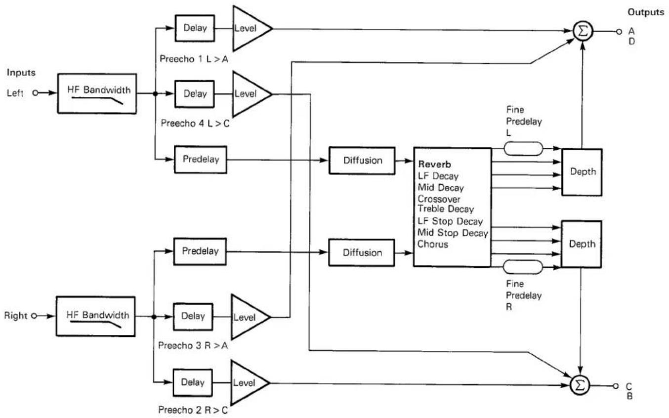
flowchart
graph TD
    A["Inputs Left"] --> B["HF Bandwidth"]
    B --> C1["Predelay"]
    C1 --> D1["Diffusion"]
    D1 --> E1["Reverb LF Decay Mid Decay Crossover Treble Decay LF Stop Decay Mid Stop Decay Chorus"]
    E1 --> F1["Output"]
    B --> G1["Predelay"]
    G1 --> H1["Diffusion"]
    H1 --> I1["Output"]
    B --> J1["Predelay"]
    J1 --> K1["Diffusion"]
    K1 --> L1["Output"]
    B --> M1["Predelay"]
    M1 --> N1["Diffusion"]
    N1 --> O1["Output"]
    B --> P1["Predelay"]
    P1 --> Q1["Diffusion"]
    Q1 --> R1["Output"]
    B --> S1["Predelay"]
    S1 --> T1["Diffusion"]
    T1 --> U1["Output"]
    B --> V1["Predelay"]
    V1 --> W1["Diffusion"]
    W1 --> X1["Output"]
    B --> Y1["Predelay"]
    Y1 --> Z1["Diffusion"]
    Z1 --> AA1["Output"]
    B --> AB1["Predelay"]
    AB1 --> AC1["Diffusion"]
    AC1 --> AD1["Output"]
    B --> AE1["Predelay"]
    AE1 --> AF1["Diffusion"]
    AF1 --> AG1["Output"]
    B --> AH1["Predelay"]
    AH1 --> AI1["Diffusion"]
    AI1 --> AJ1["Output"]
    B --> AK1["Predelay"]
    AK1 --> AL1["Diffusion"]
    AL1 --> AM1["Output"]
    B --> AN1["Predelay"]
    AN1 --> AO1["Diffusion"]
    AO1 --> AP1["Output"]
    B --> AQ1["Predelay"]
    AQ1 --> AR1["Diffusion"]
    AR1 --> AS1["Output"]
    B --> AT1["Predelay"]
    AT1 --> AU1["Diffusion"]
    AU1 --> AV1["Output"]
    B --> AW1["Predelay"]
    AW1 --> AX1["Diffusion"]
    AX1 --> AY1["Output"]

Fig. 4.3. Reverb: Chamber.

flowchart
graph LR
    A["Inputs"] --> B["Σ"]
    C["Left"] --> B
    D["Right"] --> B
    B --> E["HF Bandwidth"]
    E --> F["Predelay"]
    F --> G["Diffusion"]
    G --> H["Reverb"]
    H --> I["Σ"]
    I --> J["A"]
    I --> K["B"]
    I --> L["D"]
    I --> M["C"]
Programs
Fig. 4.4. Reverb: Rich Chamber, Dark Chamber.
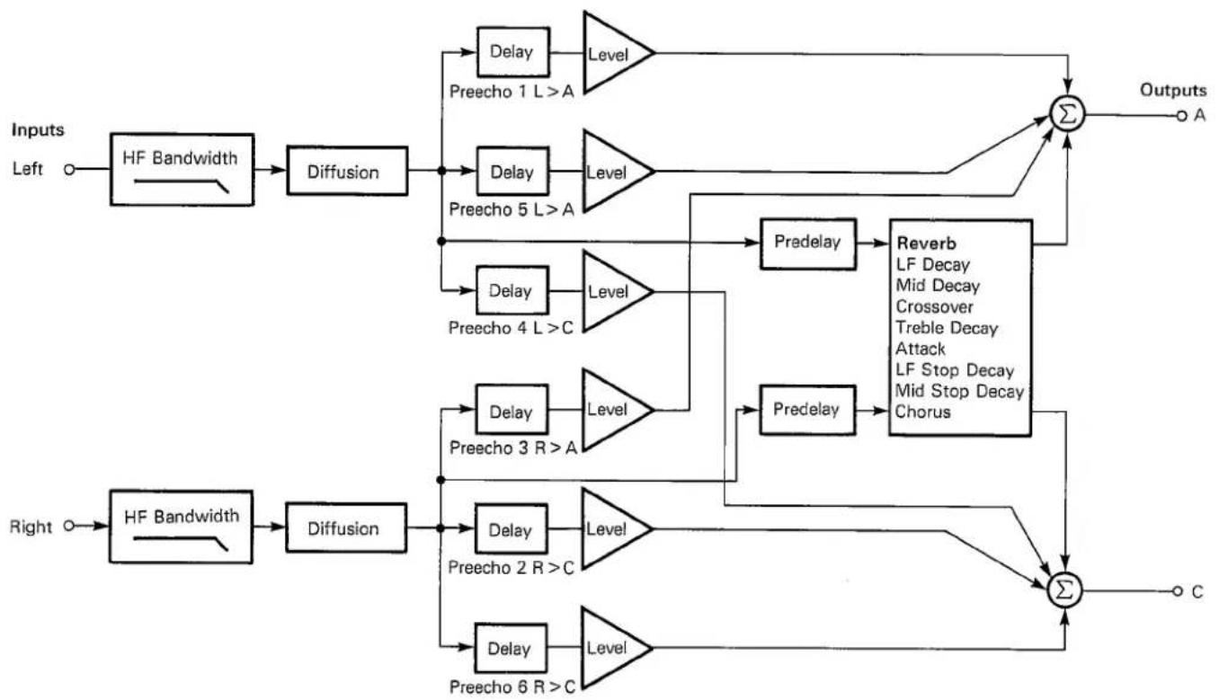
flowchart
graph TD
    A["Inputs Left"] --> B["HF Bandwidth"]
    B --> C["Diffusion"]
    C --> D1["Delay"]
    D1 --> E1["Level"]
    D1 --> F1["Preecho 1 L > A"]
    C --> D2["Delay"]
    D2 --> E2["Level"]
    D2 --> F2["Preecho 5 L > A"]
    C --> D3["Delay"]
    D3 --> E3["Level"]
    D3 --> F3["Preecho 4 L > C"]
    C --> D4["Delay"]
    D4 --> E4["Level"]
    D4 --> F4["Predelay"]
    D4 --> G1["Predelay"]
    E1 --> H1["Reverb LF Decay Mid Decay Crossover Treble Decay Attack LF Stop Decay Mid Stop Decay Chorus"]
    E2 --> H2["Predelay"]
    E3 --> H3["Predelay"]
    G1 --> I["Σ"]
    G2 --> I
    G3 --> I
    G4 --> I
    H1 --> J["Output C"]
    H2 --> J
    H3 --> J
    H4 --> J
    I --> K["Σ"]
Fig. 4.5. Reverb: Plate, Small Plate, CD Plate A, CD Plate B, Rich Plate.

flowchart
graph TD
    A["Inputs Left"] --> B["HF Bandwidth"]
    B --> C1["Delay"]
    B --> C2["Level"]
    C1 --> D1["Preecho 1 L>AD"]
    C2 --> D2["Level"]
    D1 --> E1["Predelay"]
    D2 --> E2["Level"]
    E1 --> F1["Diffusion"]
    E2 --> F2["Diffusion"]
    F1 --> G1["Reverb LF Decay Mid Decay Crossover Treble Decay Attack LF Stop Decay Mid Stop Decay Chorus"]
    F2 --> G2["Output"]
    G1 --> H["Σ"]
    G2 --> H
    H --> I["Outputs A D"]

    J["Right O"] --> K["HF Bandwidth"]
    K --> L1["Delay"]
    K --> L2["Level"]
    L1 --> M1["Predelay"]
    L2 --> M2["Level"]
    M1 --> N1["Predelay"]
    M2 --> N2["Level"]
    N1 --> O1["Diffusion"]
    N2 --> O2["Diffusion"]
    O1 --> P["Σ"]
    O2 --> P
    P --> Q["C B"]

    style A fill:#fff,stroke:#000
    style J fill:#fff,stroke:#000
    style K fill:#fff,stroke:#000

Programs
Fig. 4.6. Effects: Chorus & Echo.
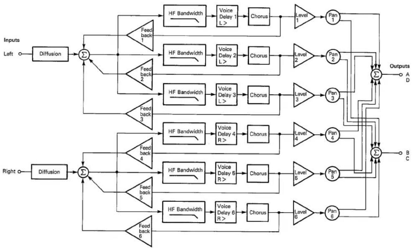
flowchart
graph TD
    A["Inputs Left"] --> B["Diffusion"]
    B --> C["Σ"]
    C --> D["HF Bandwidth"]
    D --> E["Voice Delay 1 L >"]
    E --> F["Chorus"]
    F --> G["Level 1"]
    G --> H["Pan 1"]
    H --> I["Σ"]
    I --> J["A"]
    I --> K["B"]
    I --> L["C"]
    C --> M["HF Bandwidth"]
    M --> N["Voice Delay 2 L >"]
    N --> O["Chorus"]
    O --> P["Level 2"]
    P --> Q["Pan 2"]
    Q --> I
    C --> R["HF Bandwidth"]
    R --> S["Voice Delay 3 L >"]
    S --> T["Chorus"]
    T --> U["Level 3"]
    U --> V["Pan 3"]
    V --> I
    C --> W["HF Bandwidth"]
    W --> X["Voice Delay 4 R >"]
    X --> Y["Chorus"]
    Y --> Z["Level 4"]
    Z --> AA["Pan 4"]
    AA --> I
    C --> AB["HF Bandwidth"]
    AB --> AC["Voice Delay 5 R >"]
    AC --> AD["Chorus"]
    AD --> AE["Level 5"]
    AE --> AF["Pan 5"]
    AF --> I
    C --> AG["HF Bandwidth"]
    AG --> AH["Voice Delay 6 R >"]
    AH --> AI["Chorus"]
    AI --> AJ["Level 6"]
    AJ --> AK["Pan 6"]
    AK --> I
    style A fill:#f9f,stroke:#333
    style B fill:#ccf,stroke:#333
    style C fill:#cfc,stroke:#333
    style D fill:#fcc,stroke:#333
    style E fill:#cff,stroke:#333
    style F fill:#ffc,stroke:#333
    style G fill:#fcf,stroke:#333
    style H fill:#cff,stroke:#333
    style I fill:#ffc,stroke:#333
    style J fill:#cfc,stroke:#333
    style K fill:#fcc,stroke:#333
    style L fill:#cfc,stroke:#333
    style M fill:#fcc,stroke:#333
    style N fill:#cff,stroke:#333
    style O fill:#ffc,stroke:#333
    style P fill:#fcc,stroke:#333
    style Q fill:#cfc,stroke:#333
    style R fill:#fcc,stroke:#333
    style S fill:#cff,stroke:#333
    style T fill:#ffc,stroke:#333
    style U fill:#cfc,stroke:#333
    style V fill:#fcc,stroke:#333
    style W fill:#fcc,stroke:#333
    style X fill:#cfc,stroke:#333
    style Y fill:#fcc,stroke:#333
    style Z fill:#cfc,stroke:#333
    style AA fill:#cfc,stroke:#333
    style AB fill:#fcc,stroke:#333
    style AC fill:#fcc,stroke:#333
    style AD fill:#cfc,stroke:#333
    style AE fill:#fcc,stroke:#333
    style AF fill:#cfc,stroke:#333
    style AG fill:#fcc,stroke:#333

Fig. 4.7. Effects: Resonant Chords.

flowchart
graph TD
    A["Inputs Left"] --> B["Σ"]
    B --> C["Predelay 1"]
    C --> D["Σ"]
    D --> E["HF Cutoff L"]
    E --> F["Pitch (Delay) L > 1"]
    F --> G["Level 1"]
    G --> H["Pan 1"]
    H --> I["Σ"]
    I --> J["A"]
    I --> K["D"]
    B --> L["Predelay 2"]
    L --> M["Σ"]
    M --> N["HF Cutoff L"]
    N --> O["Pitch (Delay) L > 2"]
    O --> P["Level 2"]
    P --> Q["Pan 2"]
    Q --> I
    B --> R["Predelay 3"]
    R --> S["Σ"]
    S --> T["HF Cutoff L"]
    T --> U["Pitch (Delay) L > 3"]
    U --> V["Level 3"]
    V --> W["Pan 3"]
    W --> I
    B --> X["Predelay 4"]
    X --> Y["Σ"]
    Y --> Z["HF Cutoff R"]
    Z --> AA["Pitch (Delay) R > 4"]
    AA --> AB["Level 4"]
    AB --> AC["Pan 4"]
    AC --> I
    B --> AD["Predelay 5"]
    AD --> AE["Σ"]
    AE --> AF["HF Cutoff R"]
    AF --> AG["Pitch (Delay) R > 5"]
    AG --> AH["Level 5"]
    AH --> AI["Pan 5"]
    AI --> I
    B --> AJ["Predelay 6"]
    AJ --> AK["Σ"]
    AK --> AL["HF Cutoff R"]
    AL --> AM["Pitch (Delay) R > 6"]
    AM --> AN["Level 6"]
    AN --> AO["Pan 6"]
    AO --> I
    B --> AP["Crossfeed 1"]
    AP --> AQ["Resonance 1"]
    AQ --> AR["Crossfeed 2"]
    AR --> AS["Resonance 2"]
    AS --> AT["Crossfeed 3"]
    AT --> AU["Resonance 3"]
    AU --> AV["Crossfeed 4"]
    AV --> AW["Resonance 4"]
    AW --> AX["Crossfeed 5"]
    AX --> AY["Resonance 5"]
    AY --> AZ["Crossfeed 6"]
    AZ --> BA["Resonance 6"]
    BA --> BB["Crossfeed 7"]
    BB --> BC["Resonance 7"]
    BC --> BD["Crossfeed 8"]
    BD --> BE["Resonance 8"]
    BE --> BF["Crossfeed 9"]
    BF --> BG["Resonance 9"]
    BG --> BH["Crossfeed 10"]
    BH --> BI["Resonance 10"]
    BI --> BJ["Crossfeed 11"]
    BJ --> BK["Resonance 11"]
    BK --> BL["Crossfeed 12"]
    BL --> BM["Resonance 12"]
    BM --> BN["Crossfeed 13"]
    BN --> BO["Resonance 13"]
    BO --> BP["Crossfeed 14"]
    BP --> BQ["Resonance 14"]
    BQ --> BR["Crossfeed 15"]
    BR --> BS["Resonance 15"]
    BS --> BT["Crossfeed 16"]
    BT --> BU["Resonance 16"]
    BU --> BV["Crossfeed 17"]
    BV --> BW["Resonance 17"]
    BW --> BX["Crossfeed 18"]
    BX --> BY["Resonance 18"]
    BY --> BZ["Crossfeed 19"]
    BZ --> CA["Resonance 19"]
    CA --> CB["Crossfeed 20"]
    CB --> CC["Resonance 20"]
    CC --> CD["Crossfeed 21"]
    CD --> CE["Resonance 21"]
    CE --> CF["Crossfeed 22"]
    CF --> CG["Resonance 22"]
    CG --> CH["Crossfeed 23"]
    CH --> CI["Resonance 23"]
    CI --> CJ["Crossfeed 24"]
    CJ --> CK["Resonance 24"]
    CK --> CL["Crossfeed 25"]
    CL --> CM["Resonance 25"]
    CM --> CN["Crossfeed 26"]
    CN --> CO["Resonance 26"]
    CO --> CP["Crossfeed 27"]
    CP --> CQ["Resonance 27"]
    CQ --> CR["Crossfeed 28"]
    CR --> CS["Resonance 28"]
    CS --> CT["Crossfeed 29"]
    CT --> CU["Resonance 29"]
    CU --> CV["Crossfeed 30"]
Programs
Fig. 4.8. Effects: Multiband Delay.

flowchart
graph TD
    A["Inputs Left"] --> B["Σ"]
    C["Right o"] --> B
    B --> D["Diffusion"]
    D --> E["Σ"]
    E --> F["Band Delay 1"]
    E --> G["Band Delay 2"]
    E --> H["Band Delay 3"]
    E --> I["Band Delay 4"]
    E --> J["Band Delay 5"]
    E --> K["Band Delay 6"]
    F --> L["Level 5"]
    G --> M["Level 4"]
    H --> N["Level 3"]
    I --> O["Level 2"]
    J --> P["Level 1"]
    K --> Q["Level 1"]
    L --> R["LF Cutoff"]
    M --> S["LF Cutoff"]
    N --> T["LF Cutoff"]
    O --> U["LF Cutoff"]
    P --> V["LF Cutoff"]
    Q --> W["LF Cutoff"]
    R --> X["HF Cutoff"]
    S --> Y["HF Cutoff"]
    T --> Z["HF Cutoff"]
    U --> AA["HF Cutoff"]
    V --> AB["HF Cutoff"]
    W --> AC["HF Cutoff"]
    X --> AD["HF Cutoff"]
    Y --> AE["HF Cutoff"]
    Z --> AF["Pan 4"]
    AA --> AG["Pan 3"]
    AB --> AH["Pan 2"]
    AC --> AI["Pan 1"]
    AD --> AJ["Σ"]
    AE --> AK["Σ"]
    AF --> AL["Outputs A D"]
    AG --> AM["Outputs C B"]
    AH --> AN["Feedback 1"]
    AI --> AO["Feedback 2"]
    AJ --> AP["Feedback 1"]
    AK --> AQ["Feedback 2"]

Fig. 4.9. Splits: Hall/Hall.


flowchart
graph TD
    A["Inputs Left"] --> B["HF Bandwidth"]
    B --> C1["Delay Preecho 2 L>C"]
    B --> C2["Delay Preecho 1 L>A"]
    B --> C3["Predelay L"]
    C1 --> D1["Level"]
    C2 --> D2["Level"]
    C3 --> D3["Diffusion"]
    D1 --> E1["Reverb L LF Decay, Mid Decay, Crossover, Treble Decay, LF Stop Decay, Mid Stop Decay, Chorus LR"]
    D2 --> E2["Reverb L LF Decay, Mid Decay, Crossover, Treble Decay, LF Stop Decay, Mid Stop Decay, Chorus LR"]
    D3 --> E3["Reverb R LF Decay, Mid Decay, Crossover, Treble Decay, Chorus LR"]
    D1 --> F1["Σ"]
    D2 --> F2["Σ"]
    D3 --> F3["Σ"]
    F1 --> G1["Output C"]
    F2 --> G2["Output C"]
    F3 --> G3["Output A"]
    F1 --> H1["Output D"]
    F2 --> H2["Output D"]
    F3 --> H3["Output B"]
    F1 --> I1["Output D"]
    F2 --> I2["Output D"]
    F3 --> I3["Output D"]

Programs
Fig. 4.10. Splits: Plate/Plate.

flowchart
graph TD
    A["Inputs Left"] --> B["HF Bandwidth"]
    B --> C1["Delay Preecho 2 L > C"]
    B --> C2["Delay Preecho 1 L > A"]
    B --> C3["Predelay L"]
    C3 --> D1["Diffusion"]
    D1 --> E1["Reverb L LF Decay, Mid Decay, Crossover, Treble Decay, LF Stop Decay, Mid Stop Decay, Attack, Chorus LR"]
    E1 --> F1["Σ"]
    E1 --> G1["Fine Predelay L"]
    G1 --> H1["Σ"]
    H1 --> I1["C"]
    H1 --> J1["A"]
    H1 --> K1["B"]
    H1 --> L1["D"]
    M["Right"] --> N["HF Bandwidth"]
    N --> O1["Predelay R"]
    O1 --> P1["Diffusion"]
    P1 --> Q1["Reverb R LF Decay, Mid Decay, Crossover, Treble Decay, Attack, Chorus LR"]
    Q1 --> R1["Fine Predelay R"]
    R1 --> S1["Σ"]
    R1 --> T1["D"]
    N --> U1["Predelay R"]
    U1 --> V1["Diffusion"]
    V1 --> W1["Reverb R LF Decay, Mid Decay, Crossover, Treble Decay, Attack, Chorus LR"]
    W1 --> X1["Σ"]
    W1 --> Y1["D"]
    N --> Z1["Predelay R"]
    Z1 --> AA1["Diffusion"]
    AA1 --> AB1["Reverb R LF Decay, Mid Decay, Crossover, Treble Decay, Attack, Chorus LR"]
    AB1 --> AC1["Σ"]
    AB1 --> AD1["D"]

Fig. 4.11. Splits: Plate/Hall, Rich Split.


flowchart
graph TD
    A["Inputs Left"] --> B["HF Bandwidth"]
    B --> C1["Delay"]
    C1 --> D1["Level"]
    D1 --> E1["Reverb L LF Decay, Mid Decay, Crossover, Treble Decay, LF Stop Decay, Mid Stop Decay, Attack, Chorus LR"]
    B --> C2["Delay"]
    C2 --> D2["Level"]
    D2 --> E2["Reverb R Same controls as above"]
    B --> C3["Predelay L"]
    C3 --> D3["Diffusion"]
    D3 --> E3["Σ"]
    E3 --> F1["Outputs C"]
    B --> C4["Predelay R"]
    C4 --> D4["Diffusion"]
    D4 --> E4["Σ"]
    E4 --> F2["Outputs A"]
    B --> C5["Predelay 3 R > B"]
    C5 --> D5["Level"]
    D5 --> E5["Σ"]
    E5 --> F3["Outputs B"]
    B --> C6["Predelay 4 R > D"]
    C6 --> D6["Level"]
    D6 --> E6["Σ"]
    E6 --> F4["Outputs D"]

Programs
Fig. 4.12. Splits: Plate/Chorus.

flowchart
graph TD
    A["Inputs Left"] --> B["HF Bandwidth"]
    B --> C["Predelay L"]
    C --> D["Diffusion"]
    D --> E["Reverb L\nLF Decay, Mid Decay,\nCrossover, Treble Decay,\nLF Stop Decay,\nMid Stop Decay,\nAttack"]
    E --> F["A"]
    E --> G["C"]
    F --> H["HF Bandwidth"]
    G --> I["HF Bandwidth"]
    H --> J["Voice Delay 1 R>"]
    J --> K["Chorus"]
    K --> L["Feedback 1"]
    L --> M["Level 1"]
    M --> N["Pan 1"]
    N --> O["Σ"]
    O --> P["B"]
    O --> Q["D"]
    Q --> R["HF Bandwidth"]
    R --> S["Voice Delay 2 R>"]
    S --> T["Chorus"]
    T --> U["Feedback 2"]
    U --> V["Level 2"]
    V --> W["Pan 2"]
    W --> X["Σ"]
    X --> Y["B"]
    X --> Z["D"]
    Y --> AA["HF Bandwidth"]
    Z --> AB["HF Bandwidth"]
    AA --> AC["Voice Delay 3 R>"]
    AC --> AD["Chorus"]
    AD --> AE["Feedback 3"]
    AE --> AF["Level 3"]
    AF --> AG["Pan 3"]
    AG --> AH["Σ"]
    AH --> AI["B"]
    AH --> AJ["D"]
    AI --> AK["HF Bandwidth"]
    AJ --> AL["HF Bandwidth"]
    AK --> AM["Voice Delay 4 R>"]
    AM --> AN["Chorus"]
    AN --> AO["Feedback 4"]
    AO --> AP["Level 4"]
    AP --> AQ["Pan 4"]
    AQ --> AR["Σ"]
    AR --> AS["B"]
    AR --> AT["D"]
    AT --> AU["HF Bandwidth"]
    AU --> AV["Voice Delay 5 R>"]
    AV --> AW["Chorus"]
    AW --> AX["Feedback 5"]
    AX --> AY["Level 5"]
    AY --> AZ["Pan 5"]
Applications

| This section gives a brief introduction to four general reverberation effects possible from the 224X and then gives some specific examples of how to achieve these effects. In addition, it describes applications of the 224X's special | effects programs and gives representative set-ups for those applications. Sonic shading and effects are highly subjective; these applications are meant to serve as general introductions and as starting points for experimentation. |
5.1
Reverberation Programs
5.1.1 Re-creating Room Acoustics
The reverberation programs in the 224X can be used to add a realistic impression of a particular place to sonic material. This capability is obviously important for dialog and effects in broadcast or film, but realistic acoustics can be just as important in creating a mood to enhance a drum track or instrument. The choice of program depends on the mood wanted. Try the Rich Chamber or Dark Chamber first, adjusting the size and reverb time to match the material. Large sizes with predelay and preechoes sound very spacious,
and smaller sizes sound tight. The Small Room program is excellent for a mood of confined pressure, the Room program for a natural open sound, and the Concert Hall program for space or grandeur. When a hall is wanted for drums or popular music, try the Bright Hall program. For dialog or classical music, try the Dark Hall program. The Plate program, with predelays of about 100 milliseconds and preechoes (try variation 4), can sometimes be useful in emulating a large space.
5.1.2 Creating Space or Ambience
Ambience gives sonic material a sense of being real — of being actually performed in a particular place at a particular time. Very little reverberation need be used to create this illusion; no mudding or blurring of the material need take place. This use of the 224X is very similar to re-creating room acoustics, but larger spaces are usually used and not many
returns are used in the mix, so the particular space chosen is not obvious. This reverberation effect is commonly used for material that has already been mixed, such as classical music or a completed popular production. Again, the Bright Hall program is a good choice for drums or pop, and the Concert Hall or Dark Hall programs for classical music.
5.1.3 Thickening or Enriching Single Tracks
The bulk of reverberation in popular music production is used to thicken or enrich single tracks. Generally, the 224X Plate programs are best, because no definite sense of size or acoustic quality is wanted in a mixdown. Some engineers prefer the natural acoustic
quality of the Room program in a mix, and the Small Room or Rich Chamber programs can also produce interesting results. There are no rules for thickening with the 224X — even the Effects or Split programs can be useful.
5.1.4 Adding Loudness Without Increasing Peak Level
Closely miked material can often sound much softer than its peak recorded level would indicate, and an important use of reverberation is to increase loudness before cutting or broadcast. In this application, the Small Room program is very effective on dialog and on music when short reverb times are used.
A depth of about 60 gives more apparent level with less peak level. The Rich Chamber program is good when average reverb decay times of more than 1 second are used. Variation 3 of the Inverse Room program may also be very useful in adding loudness.
Applications
5.1.5 Examples of General Applications
Using the Reverbation Programs with Specific Sources
Drums
1
Room Acoustics — try the Rich Chamber (variation 4), the Room (variation 1 or 2) and the Small Room (variations 1 and 2) programs. Also, the Bright Hall program has a bright sound and high enough diffusion to be successful with drums, and it gives a large, spacious sound.
2
Ambience — try the Rich Chamber or Rich Plate, with some pre-delay, or the Bright Hall program (variation 1 or 2); you don't need to add very much.
3
Thickening — try the Rich Plate program (variation 1 or 4). Set the low-frequency reverb decay time to less than 1 second, which can give a lighter sound. The Small Room program, with average reverb decay times of 0.6 second or less, simulates a drum cage, giving a much richer sound to a drum kit. The Constant-Density Plate B program produces a sound many engineers like on drums.
4
Adding Loudness — try the Rich Chamber, the Small Room program or the Inverse Room.
Vocals
1
Acoustics — try the Rich Chamber at different sizes, or the Concert Hall, Room, and Small Room programs (variation 1 or 2). The different sizes in these programs give quite different moods. Set the stopped reverb decay times (page 2, sliders 1 and 2) higher than running reverb decay times (page 1, sliders 1 and 2), and turn on the Dynamic Decay toggle (dynamic decay is preset on in variation 6 of the Concert Hall program). Variation 2 of the Concert Hall, Dark Hall, Bright Hall, Room, and Small Room programs has preset preechoes added to emulate the floor and back walls of a stage area. These variations increase the sense of distance between the performer and the pick-up.
2
Ambience — try the Rich Chamber, Concert Hall, or Dark Hall programs. Again, the pre-echoes in variation 2 may help.
3
Thickening — try the Rich Plate, Plate or Room programs. Variation 2 of the Plate program has low diffusion and a very interesting
clear sound on vocals. The Constant-Density Plate B program is also excellent. The Plate/Chorus program can be useful.
4
Loudness — try the Rich Chamber or Inverse Room program.
Dialog
1
Acoustics — dialog is very similar to vocals, but much less return should be added to the mix. The Small Room, Room, Dark Hall, and Rich Chamber programs can all be used, depending on the size and mood wanted. Variation 2 of these programs adds pre-echoes and gives a harder sound. Dynamic decay was originally developed for dialog and can be tried by turning on the Dynamic Decay Toggle.
2
Ambience — use the Dark Chamber, Dark Hall or Rich Chamber programs.
3
Thickening — try the Rich Chamber (small size), Small Room, Plate, Small Plate, Rich Chamber, or Constant-Density Plate B programs.
4
Loudness — try the Small Room, Rich Chamber, or Inverse Room programs.
Orchestra
1
Acoustics — a small group might sound more natural using the Room and Small Room programs, but the Dark Chamber program should almost always be tried first. Variation 2 adds preechoes that sound natural on symphonic or vocal material. The Rich Chamber program is also valuable for this application; the predelay can be set to 120 milliseconds, and a few preechoes can be used to fill in the time between the input and the reverb. This configuration gives a good sense of space with less color than is available from the Dark Hall program.
2
Ambience — the Dark Hall program gives the most realistic sense of space.
3
Thickening — try the Rich Chamber program with short predelay and with average reverb decay times of 1 to 2 seconds.
4
Loudness — try the Rich Chamber program.
5.2
Effects Programs
The 224X's Effects programs are more variable and even more subjective than the reverberation programs. Applications depend in large part on musical styles, context, and the intent of an artist or producer.
Although the 224X Effects programs can produce an enormous array of different sounds, many of the common uses can be grouped into a few general classes of functions. These functions consist of:

Enrichment or Thickening

Doubling, Chorusing, and Flanging

Repeats

Sound Modification
The following sections describe a few applications for these functions.
5.2.1 Enrichment or Thickening
In contemporary production, much attention is given to achieving the quality of fullness in sound. Each of the effects programs can increase the fullness or richness of musical parts. The extraordinary amount of variability within each program allows a broad palette of distinctive sounds. For instance, it is very easy to take a simple chorus and add repeats by increasing the delay time of one of the delay taps, or "voices." In addition, the independent processing of inputs (Chorus & Echo, Resonant Chords, and Plate/Chorus) allows a user to create more than one effect simultaneously.
The general form of an "enrichment" setup is one or more short delay taps combined with the original signal. The delay times selected depend on the type of sound desired and the input material. Very short delays are likely to affect the tone quality of the source through phase cancellation. If the delays are too long, they are heard as discrete repeats or "slaps." Percussive material tends to accentuate the discreteness of the delays, but slaps can be smoothed with the Diffusion control in the Chorus & Echo and Multiband Delay programs. Vocals or other nonpercussive inputs can use longer delay times and lower diffusion.
The number of delay taps that is mixed in (level settings above 0) also has a marked effect on the type of sound achieved. Generally speaking, the greater the number of delay taps brought into play, the thicker the sound. Phase cancellations between the taps can be used to color the sound, and panning the various taps to different points in the stereo field can create a dramatic sense of dimensionality.
Recirculation of the delays forms a resonant "comb" filter and colors the sound (an effect exploited by the Resonant Chords program). The result can be both interesting and bizarre.
The Chorus & Echo, Resonant Chords, and Plate/Chorus programs can also be used in "series" by routing the outputs of one side into the input of the other. The results can be very interesting — for example, the Plate/Chorus program can add reverberation to all voices of a 5-voice chorus, giving a combination that is particularly effective on synthesizer or vocals.
The Chorus & Echo program is most effective when an element of motion is desired, as in actual chorusing or flanging (see Sec. 5.2.2). The Resonant Chords program can be used for enrichment if the Resonance parameter for each tap is reduced. The Multiband Delay program can be used to delay different frequency bands by different amounts, creating richness without comb-filter effects. The Plate/Chorus program is useful when an element of room acoustics is desired along with or on top of the thickening function.
Tables 5.1 to 5.4 show possible setups for thickening, using each of the Effects programs. These setups represent just four of thousands of possible, and useful, enrichment setups. Use the values detailed in the tables as starting points to create your own distinct sounds. With the memory storage and cassette interface of the 224X with LARC, an engineer, artist, or producer can create a library of setups that can be used in the future.
Applications
Table 5.1. Enrichment 1 – Chorus & Echo Program.
| Page | Variable Parameters and Ranges | |||||
| Chorus | HF Bandwidth | Diffusion | ||||
| 1 | Inactive | Inactive | 69 | 19.0 kHz | 00 | Inactive |
| Voice Level 1 L> | Voice Level 2 L> | Voice Level 3 L> | Voice Level 4 R> | Voice Level 5 R> | Voice Level 6 R> | |
| 2 | 56 | 56 | 50 | 61 | 41 | 48 |
| Voice Delay 1 L> | Voice Delay 2 L> | Voice Delay 3 L> | Voice Delay 4 R> | Voice Delay 5 R> | Voice Delay 6 R> | |
| 3 | 12.0 msec | 23.0 msec | 38.0 msec | 7.00 msec | 10.0 msec | 33.0 msec |
| Feedback 1 L> | Feedback 2 L> | Feedback 3 L> | Feedback 4 R> | Feedback 5 R> | Feedback 6 R> | |
| 4 | 00% | 00% | 00% | -28% | -12% | 09% |
| Pan 1 | Pan 2 | Pan 3 | Pan 4 | Pan 5 | Pan 6 | |
| 5 | 00 | 99 | 50 | 37 | 00 | 99 |
| 1 | 2 | 3 | 4 | 5 | 6 | |
| Sliders | ||||||
Table 5.2. Enrichment 2 — Resonant Chords Program.
| Page | Variable Parameters and Ranges | |||||
| NoteLevel 1L> | NoteLevel 2L> | NoteLevel 3L> | NoteLevel 4R> | NoteLevel 5R> | NoteLevel 6R> | |
| 1 | 69 | 45 | 41 | 58 | 45 | 56 |
| NotePitch 1L> | NotePitch 2L> | NotePitch 3L> | NotePitch 4R> | NotePitch 5R> | NotePitch 6R> | |
| 2 | 4.40 msec | 5.87 msec | 6.96 msec | 8.75 msec | 11.6 msec | 17.3 msec |
| Resonance1 L> | Resonance2 L> | Resonance3 L> | Resonance4 R> | Resonance5 R> | Resonance6 R> | |
| 3 | 50% | 53% | 28% | 28% | 47% | 59% |
| Predelay1 L> | Predelay2 L> | Predelay3 L> | Predelay4 R> | Predelay5 R> | Predelay6 R> | |
| 4 | 12.0 msec | 24.0 msec | 36.0 msec | 28.0 msec | 56.0 msec | 44.0 msec |
| Pan 1 | Pan 2 | Pan 3 | Pan 4 | Pan 5 | Pan 6 | |
| 5 | 00 | 99 | 31 | 89 | 06 | 58 |
| Crossfeed | Crossfeed | HF CutoffL | HF CutoffR | |||
| 6 | 00% | 00% | 4.90 kHz | 11.3 kHz | Inactive | Inactive |
| 1 | 2 | 3 | 4 | 5 | 6 | |
| Sliders | ||||||


Applications
Table 5.3. Enrichment 3 — Multiband Delay Program.
| Page | Variable Parameter Settings | |||||
| BandLevel 1L+R> | BandLevel 2L+R> | BandLevel 3L+R> | BandLevel 4L+R> | BandLevel 5L+R> | BandLevel 6L+R> | |
| 1 | 50 | 50 | 50 | 50 | 50 | 50 |
| BandDelay 1L+R> | BandDelay 2L+R> | BandDelay 3L+R> | BandDelay 4L+R> | BandDelay 5L+R> | BandDelay 6L+R> | |
| 2 | 6.00 msec | 16.0 msec | 12.0 msec | 16.0 msec | 27.0 msec | 36.0 msec |
| LF Cutoff1 L+R> | LF Cutoff2 L+R> | LF Cutoff3 L+R> | LF Cutoff4 L+R> | LF Cutoff5 L+R> | LF Cutoff6 L+R> | |
| 3 | 170 Hz | 350 Hz | 530 Hz | 1.13 kHz | 3.80 kHz | 19.0 kHz |
| HF Cutoff1 L+R> | HF Cutoff2 L+R> | HF Cutoff3 L+R> | HF Cutoff4 L+R> | HF Cutoff5 L+R> | HF Cutoff6 L+R> | |
| 4 | 170 Hz | 350 Hz | 530 Hz | 1.13 kHz | 3.80 kHz | 19.0 kHz |
| Pan 1 | Pan 2 | Pan 3 | Pan 4 | Pan 5 | Pan 6 | |
| 5 | 00 | 06 | 28 | 52 | 74 | 91 |
| Feedback1 | Feedback2 | Diffusion | ||||
| 6 | 00 | 00 | Inactive | Inactive | 33 | Inactive |
| 1 | 2 | 3 | 4 | 5 | 6 | |
| Sliders | ||||||
Table 5.4. Enrichment 4 — Plate/Chorus Program.
| Page | Variable Parameter Settings | |||||
| LF Decay L | Mid Decay L | Crossover L | Treble Decay L | Attack L | Predelay L | |
| 1 | 0.6 sec | 0.6 sec | 1.13 kHz | 19.0 kHz | 00 | 0.00 msec |
| LF Stop Decay L | Mid Stop Decay L | Chorus R | HF Bandwidth L | Diffusion L | Definition L | |
| 2 | 3.0 sec | 3.0 sec | 44 | 9.0 kHz | 28 | 00 |
| Voice Level 1 | Voice Level 2 | Voice Level 3 | Voice Level 4 | Voice Level 5 | ||
| R> | R> | R> | R> | R> | ||
| 3 | 50 | 50 | 44 | 44 | 37 | Inactive |
| Voice Delay 1 R> | Voice Delay 2 R> | Voice Delay 3 R> | Voice Delay 4 R> | Voice Delay 5 R> | ||
| 4 | 5.50 msec | 7.00 msec | 3.50 msec | 5.50 msec | 9.00 msec | Inactive |
| Feedback 1 R> | Feedback 2 R> | Feedback 3 R> | Feedback 4 R> | Feedback 5 R> | ||
| 5 | 09% | -06% | 06% | -03% | 00% | Inactive |
| Pan 1 | Pan 2 | Pan 3 | Pan 4 | Pan 5 | ||
| 6 | 60 | 99 | 25 | 75 | 50 | Inactive |
| 1 | 2 | 3 | 4 | 5 | 6 | |
| Sliders | ||||||


Applications
5.2.2 Doubling, Chorusing, and Flanging
Double tracking and chorusing are perhaps the most popular of all effects. Although they might be classed as forms of enrichment, they are distinct enough to merit their own discussion. In double tracking (also known as doubling or artificial double tracking), the intent is to create a realistic imitation of the effect of a sound actually being "doubled" on tape.
The Chorus & Echo program provides two separate channels for doubling. The basic doubling setup consists of one delay tap set for between 15 and 30 milliseconds delay, with some modulation of the delay time. This delay tap is usually panned to the opposite side of the stereo field from the original. The Chorus parameter should be set moderately high, and no feedback should be used. Table 5.5 depicts a doubling setup for one side of the Chorus & Echo program. The other side (R input and voices 4 to 6) can be set up for an independent double, or for an entirely different effect.
Table 5.5. Doubling — Chorus & Echo Program.
| Page | Variable Parameter Settings | |||||
| Chorus | HF Bandwidth | Diffusion | ||||
| 1 | Inactive | Inactive | 97 | 19.0 kHz | 00 | Inactive |
| VoiceLevel 1L> | VoiceLevel 2L> | VoiceLevel 3L> | VoiceLevel 4R> | VoiceLevel 5R> | VoiceLevel 6R> | |
| 2 | 80 | 00 | 00 | 00 | 00 | 00 |
| VoiceDelay 1L> | VoiceDelay 2L> | VoiceDelay 3L> | VoiceDelay 4R> | VoiceDelay 5R> | VoiceDelay 6R> | |
| 3 | 18.0 msec | |||||
| Feedback1 L> | Feedback2 L> | Feedback3 L> | Feedback4 R> | Feedback5 R> | Feedback6 R> | |
| 4 | 00% | |||||
| Pan 1 | Pan 2 | Pan 3 | Pan 4 | Pan 5 | Pan 6 | |
| 5 | 00 | |||||
| 1 | 2 | 3 | 4 | 5 | 6 | |
| Sliders | ||||||
Chorusing is similar to doubling but uses a number of voices. It is very popular to exaggerate the chorus effect, so that it becomes more swirling and artificial. To achieve this effect, bring in lots of voices, turn up the modulation (Chorus parameter), place the voices very close together in time, and add recirculation around the delays. The effects can be dramatic. Table 5.6 shows a moderately thick chorus setup, somewhere between a realistic chorus and a totally artificial sound.
Table 5.6. Chorusing — Chorus & Echo Program.
| Page | Variable Parameter Settings | |||||
| Chorus | HF Bandwidth | Diffusion | ||||
| 1 | Inactive | Inactive | 97 | 19.0 kHz | 00 | Inactive |
| Voice Level 1 L> | Voice Level 2 L> | Voice Level 3 L> | Voice Level 4 R> | Voice Level 5 R> | Voice Level 6 R> | |
| 2 | 56 | 56 | 50 | 50 | 44 | 44 |
| Voice Delay 1 L> | Voice Delay 2 L> | Voice Delay 3 L> | Voice Delay 4 R> | Voice Delay 5 R> | Voice Delay 6 R> | |
| 3 | 18.0 msec | 22.0 msec | 17.0 msec | 19.0 msec | 17.0 msec | 18.0 msec |
| Feedback 1 L> | Feedback 2 L> | Feedback 3 L> | Feedback 4 R> | Feedback 5 R> | Feedback 6 R> | |
| 4 | 34% | 00% | -25% | 37% | 00% | -31% |
| Pan 1 | Pan 2 | Pan 3 | Pan 4 | Pan 5 | Pan 6 | |
| 5 | 00 | 99 | 00 | 99 | 00 | 99 |
| 1 | 2 | 3 | 4 | 5 | 6 | |
| Sliders | ||||||


Applications
Flanging effects result from having very short delays mixed together while time modulation (Chorus parameter) is in effect. This results in shifting "comb filters" in which some frequencies are canceled and some are reinforced. The motion of these notches and peaks creates the familiar "jet plane" sound.
In the Chorus & Echo program, the six output voices or delay taps, each with an independent random modulation, provide the opportunity to achieve complex flanging motion. When the taps are set for identical values, the modulations create motion around that point, and adding recirculation exaggerates the effect. By setting the delays for larger values, flanging effects can be combined with other effects, such as chorus or repeats. Tables 5.7 and 5.8 show two possibilities. Table 5.7 illustrates a basic flange, and Table 5.8 shows a flange that combines with multiple repeats for a very pronounced, swirling echo.
Table 5.7. Basic Flange.
| Page | Variable Parameter Settings | |||||
| Chorus | HF Bandwidth | Diffusion | ||||
| 1 | Inactive | Inactive | 97 | 19.0 kHz | 18 | Inactive |
| Voice Level 1 L> | Voice Level 2 L> | Voice Level 3 L> | Voice Level 4 R> | Voice Level 5 R> | Voice Level 6 R> | |
| 2 | 50 | 50 | 50 | 50 | 50 | 50 |
| Voice Delay 1 L> | Voice Delay 2 L> | Voice Delay 3 L> | Voice Delay 4 R> | Voice Delay 5 R> | Delay 6 R> | |
| 3 | 0.00 msec | 0.00 msec | 0.00 msec | 0.00 msec | 0.00 msec | 0.00 msec |
| Feedback 1 L> | Feedback 2 L> | Feedback 3 L> | Feedback 4 R> | Feedback 5 R> | Feedback 6 R> | |
| 4 | 37% | -25% | -25% | 37% | -22% | -31% |
| Pan 1 | Pan 2 | Pan 3 | Pan 4 | Pan 5 | Pan 6 | |
| 5 | 00 | 99 | 00 | 99 | 00 | 99 |
| 1 | 2 | 3 | 4 | 5 | 6 | |
| Sliders | ||||||
Table 5.8. Flange with Multiple Repeats.
| Page | Variable Parameter Settings | |||||
| Chorus | HF Bandwidth | Diffusion | ||||
| 1 | Inactive | Inactive | 97 | 19.0 kHz | 44 | Inactive |
| Voice Level 1 L> | Voice Level 2 L> | Voice Level 3 L> | Voice Level 4 R> | Voice Level 5 R> | Voice Level 6 R> | |
| 2 | 50 | 50 | 50 | 50 | 50 | 50 |
| Voice Delay 1 L> | Voice Delay 2 L> | Voice Delay 3 L> | Voice Delay 4 R> | Voice Delay 5 R> | Voice Delay 6 R> | |
| 3 | 300 msec | 300 msec | 300 msec | 300 msec | 300 msec | 300 msec |
| Feedback 1 L> | Feedback 2 L> | Feedback 3 L> | Feedback 4 R> | Feedback 5 R> | Feedback 6 R> | |
| 4 | 44% | -31% | -25% | 44% | -22% | -04% |
| Pan 1 | Pan 2 | Pan 3 | Pan 4 | Pan 5 | Pan 6 | |
| 5 | 00 | 99 | 00 | 99 | 00 | 99 |
| 1 | 2 | 3 | 4 | 5 | 6 | |
| Sliders | ||||||


Applications
5.2.3 Repeats
When delays exceed a few tens of milliseconds, discrete repetitions are heard. The multiple delay outputs of the Effects programs provide many opportunities for complex patterns of repeats. Each of the Effects programs can provide up to six distinct repeats, and recirculation, or feedback, can stretch out these repeats almost indefinitely. By using the distinct nature of each program, these repeats, or echoes, can be combined with various other types of effects with startling results. Tables 5.9 to 5.11 show just a few possible settings
Table 5.9. Repeats 1 — Chorus & Echo Program.
| Page | Variable Parameter Settings | |||||
| Chorus | HF Bandwidth | Diffusion | ||||
| 1 | Inactive | Inactive | 53 | 19.0 kHz | 25 | Inactive |
| Voice Level 1 L> | Voice Level 2 L> | Voice Level 3 L> | Voice Level 4 R> | Voice Level 5 R> | Voice Level 6 R> | |
| 2 | 99 | 00 | 00 | 99 | 00 | 00 |
| Voice Delay 1 L> | Voice Delay 2 L> | Voice Delay 3 L> | Voice Delay 4 R> | Voice Delay 5 R> | Voice Delay 6 R> | |
| 3 | 750 msec | 798 msec | ||||
| Feedback 1 L> | Feedback 2 L> | Feedback 3 L> | Feedback 4 R> | Feedback 5 R> | Feedback 6 R> | |
| 4 | 41% | 00% | 00% | 41% | 00% | 00% |
| Pan 1 | Pan 2 | Pan 3 | Pan 4 | Pan 5 | Pan 6 | |
| 5 | 00 | 99 | 00 | 99 | 00 | 99 |
| 1 | 2 | 3 | 4 | 5 | 6 | |
| Sliders | ||||||
Table 5.10. Repeats 2 — Chorus & Echo Program.
| Page | Variable Parameter Settings | |||||
| Chorus | HF Bandwidth | Diffusion | ||||
| 1 | Inactive | Inactive | 53 | 19.0 kHz | 25 | Inactive |
| Voice Level 1 L> | Voice Level 2 L> | Voice Level 3 L> | Voice Level 4 R> | Voice Level 5 R> | Voice Level 6 R> | |
| 2 | 99 | 69 | 67 | 99 | 72 | 63 |
| Voice Delay 1 | Voice Delay 2 | Voice Delay 3 | Voice Delay 4 | Voice Delay 5 | Voice Delay 6 | |
| L> | L> | L> | R> | R> | R> | |
| 3 | 750 msec | 693 msec | 728 msec | 798 msec | 644 msec | 705 msec |
| Feedback 1 L> | Feedback 2 L> | Feedback 3 L> | Feedback 4 R> | Feedback 5 R> | Feedback 6 R> | |
| 4 | 41% | 28% | 00% | 41% | 25% | 00% |
| Pan 1 | Pan 2 | Pan 3 | Pan 4 | Pan 5 | Pan 6 | |
| 5 | 00 | 99 | 00 | 99 | 00 | 99 |
| 1 | 2 | 3 | 4 | 5 | 6 | |
| Sliders | ||||||


Applications
Table 5.11. Repeats 3 — Resonant Chords Program.
| Page | Variable Parameter Settings | |||||
| NoteLevel 1L> | NoteLevel 2L> | NoteLevel 3L> | NoteLevel 4R> | NoteLevel 5R> | NoteLevel 6R> | |
| 1 | 50 | 50 | 50 | 50 | 50 | 50 |
| NotePitch 1L> | NotePitch 2L> | NotePitch 3L> | NotePitch 4R> | NotePitch 5R> | NotePitch 6R> | |
| 2 | 4.40 msec | 5.87 msec | 6.96 msec | 8.75 msec | 11.6 msec | 17.3 msec |
| Resonance1 L> | Resonance2 L> | Resonance3 L> | Resonance4 R> | Resonance5 R> | Resonance6 R> | |
| 3 | 75% | -78% | 59% | -56% | 85% | -50% |
| Predelay1 L> | Predelay2 L> | Predelay3 L> | Predelay4 R> | Predelay5 R> | Predelay6 R> | |
| 4 | 192 msec | 368 msec | 400 msec | 864 msec | 364 msec | 504 msec |
| Pan 1 | Pan 2 | Pan 3 | Pan 4 | Pan 5 | Pan 6 | |
| 5 | 25 | 66 | 15 | 88 | 25 | 96 |
| Crossfeed | Crossfeed | HF CutoffL | HF CutoffR | |||
| 6 | 00% | 61% | 19.0 kHz | 19.0 kHz | Inactive | Inactive |
| 1 | 2 | 3 | 4 | 5 | 6 | |
| Sliders | ||||||
Table 5.12. Repeats 4 — Multiband Delay Program.
| Page | Variable Parameter Settings | |||||
| BandLevel 1L+R> | BandLevel 2L+R> | BandLevel 3L+R> | BandLevel 4L+R> | BandLevel 5L+R> | BandLevel 6L+R> | |
| 1 | 50 | 50 | 50 | 50 | 50 | 50 |
| BandDelay 1L+R> | BandDelay 2L+R> | BandDelay 3L+R> | BandDelay 4L+R> | BandDelay 5L+R> | BandDelay 6L+R> | |
| 2 | 568 msec | 1.28 sec | 1.16 sec | 1.44 sec | 1.24,sec | 1.86 sec |
| LF Cutoff1 L+R> | LF Cutoff2 L+R> | LF Cutoff3 L+R> | LF Cutoff4 L+R> | LF Cutoff5 L+R> | LF Cutoff6 L+R> | |
| 3 | 720 Hz | 1.13 kHz | 5.30 kHz | 1.13 kHz | 1.57 kHz | 3.40 kHz |
| HF Cutoff1 L+R> | HF Cutoff2 L+R> | HF Cutoff3 L+R> | HF Cutoff4 L+R> | HF Cutoff5 L+R> | HF Cutoff6 L+R> | |
| 4 | 1.80 kHz | 920 Hz | 530 Hz | 1.13 kHz | 6.90 kHz | 4.90 kHz |
| Pan 1 | Pan 2 | Pan 3 | Pan 4 | Pan 5 | Pan 6 | |
| 5 | 00 | 99 | 00 | 99 | 00 | 99 |
| Feedback1 | Feedback2 | Diffusion | ||||
| 6 | 22% | 20% | Inactive | Inactive | 20 | Inactive |
| 1 | 2 | 3 | 4 | 5 | 6 | |
| Sliders | ||||||

Applications
5.2.4 Sound Modification
Sound modification is a very broad term, meaning that something is done to a sound to turn it into something new. All of the effects mentioned so far are actually sound modifications, but this section discusses more exaggerated forms that alter the basic nature of the input signal.
The Resonant Chords program provides a dramatic transformation. A percussive source is altered by using transients to "ring" a group of resonators, each consisting of a short delay being fed back strongly on itself. For each note, the pitch, duration, tone, and initial
delay of the sound can be adjusted; the various notes can be adjusted into different, related chords; and the Note Predelay parameter can be tuned to match a particular tempo. If these different tunings and adjustments are stored in memory registers, a drum track can be played into the unit and changed into a complete backing track.
The other programs can also be used to produce startling, unnatural effects for special purposes. Tables 5.13 to 5.16 show a few of the possibilities.
Table 5.13. Modification 1 — Chorus & Echo.
| Page | Variable Parameter Settings | |||||
| Chorus | HF Bandwidth | Diffusion | ||||
| 1 | Inactive | Inactive | 97 | 10.1 kHz | 00 | Inactive |
| Voice Level 1 L> | Voice Level 2 L> | Voice Level 3 L> | Voice Level 4 R> | Voice Level 5 R> | Voice Level 6 R> | |
| 2 | 56 | 56 | 50 | 50 | 44 | 44 |
| Voice Delay 1 L> | Voice Delay 2 L> | Voice Delay 3 L> | Voice Delay 4 R> | Voice Delay 5 R> | Voice Delay 6 R> | |
| 3 | 0.00 msec | 178 msec | 15.0 msec | 0.00 msec | 45.0 msec | 19.0 msec |
| Feedback 1 L> | Feedback 2 L> | Feedback 3 L> | Feedback 4 R> | Feedback 5 R> | Feedback 6 R> | |
| 4 | 97% | 00% | 00% | 97% | 00% | 00% |
| Pan 1 | Pan 2 | Pan 3 | Pan 4 | Pan 5 | Pan 6 | |
| 5 | 00 | 99 | 00 | 99 | 00 | 99 |
| 1 | 2 | 3 | 4 | 5 | 6 | |
| Sliders | ||||||
Table 5.14. Modification 2 — Resonant Chords Program.
| Page | Variable Parameter Settings | |||||
| NoteLevel 1L> | NoteLevel 2L> | NoteLevel 3L> | NoteLevel 4R> | NoteLevel 5R> | NoteLevel 6R> | |
| 1 | 50 | 50 | 50 | 50 | 50 | 50 |
| NotePitch 1L> | NotePitch 2L> | NotePitch 3L> | NotePitch 4R> | NotePitch 5R> | NotePitch 6R> | |
| 2 | 4.40 msec | 5.87 msec | 6.96 msec | 8.75 msec | 11.6 msec | 17.3 msec |
| Resonance1 L> | Resonance2 L> | Resonance3 L> | Resonance4 R> | Resonance5 R> | Resonance6 R> | |
| 3 | 97% | 97% | 97% | 97% | 97% | 97% |
| Predelay1 L> | Predelay2 L> | Predelay3 L> | Predelay4 R> | Predelay5 R> | Predelay6 R> | |
| 4 | 0.00 msec | 0.00 msec | 0.00 msec | 0.00 msec | 0.00 msec | 0.00 msec |
| Pan 1 | Pan 2 | Pan 3 | Pan 4 | Pan 5 | Pan 6 | |
| 5 | 00 | 99 | 00 | 99 | 00 | 99 |
| Crossfeed | Crossfeed | HF CutoffL | HF CutoffR | |||
| 6 | 00% | 00% | 4.10 kHz | 4.10 kHz | Inactive | Inactive |
| 1 | 2 | 3 | 4 | 5 | 6 | |
| Sliders | ||||||


Table 5.15. Modification 3 — Resonant Chords Program.
| Page | Variable Parameter Settings | |||||
| NoteLevel 1L> | NoteLevel 2L> | NoteLevel 3L> | NoteLevel 4R> | NoteLevel 5R> | NoteLevel 6R> | |
| 1 | 50 | 50 | 50 | 50 | 50 | 50 |
| NotePitch 1L> | NotePitch 2L> | NotePitch 3L> | NotePitch 4R> | NotePitch 5R> | NotePitch 6R> | |
| 2 | 4.93 msec | 6.59 msec | 7.89 msec | 9.84 msec | 13.0 msec | 19.8 msec |
| Resonance1 L> | Resonance2 L> | Resonance3 L> | Resonance4 R> | Resonance5 R> | Resonance6 R> | |
| 3 | 97% | 97% | 97% | 97% | 97% | 97% |
| Predelay1 L> | Predelay2 L> | Predelay3 L> | Predelay4 R> | Predelay5 R> | Predelay6 R> | |
| 4 | 0.00 msec | 0.00 msec | 0.00 msec | 0.00 msec | 0.00 msec | 0.00 msec |
| Pan 1 | Pan 2 | Pan 3 | Pan 4 | Pan 5 | Pan 6 | |
| 5 | 00 | 99 | 00 | 99 | 00 | 99 |
| Crossfeed | Crossfeed | HF CutoffL | HF CutoffR | |||
| 6 | 00% | 00% | 4.10 kHz | 4.10 kHz | Inactive | Inactive |
| 1 | 2 | 3 | 4 | 5 | 6 | |
| Sliders | ||||||
Table 5.16. Modification 4 — Resonant Chords Program.
| Page | Variable Parameter Settings | |||||
| NoteLevel 1L> | NoteLevel 2L> | NoteLevel 3L> | NoteLevel 4R> | NoteLevel 5R> | NoteLevel 6R> | |
| 1 | 50 | 50 | 50 | 50 | 50 | 50 |
| NotePitch 1L> | NotePitch 2L> | NotePitch 3L> | NotePitch 4R> | NotePitch 5R> | NotePitch 6R> | |
| 2 | 3.68 msec | 4.93 msec | 5.90 msec | 7.34 msec | 9.71 msec | 14.7 msec |
| Resonance1 L> | Resonance2 L> | Resonance3 L> | Resonance4 R> | Resonance5 R> | Resonance6 R> | |
| 3 | 97% | 97% | 97% | 97% | 97% | 97% |
| Predelay1 L> | Predelay2 L> | Predelay3 L> | Predelay4 R> | Predelay5 R> | Predelay6 R> | |
| 4 | 0.00 msec | 0.00 msec | 0.00 msec | 0.00 msec | 0.00 msec | 0.00 msec |
| Pan 1 | Pan 2 | Pan 3 | Pan 4 | Pan 5 | Pan 6 | |
| 5 | 00 | 99 | 00 | 99 | 00 | 99 |
| Crossfeed | Crossfeed | HF CutoffL | HF CutoffR | |||
| 6 | 00% | 00% | 4.10 kHz | 4.10 kHz | Inactive | Inactive |
| 1 | 2 | 3 | 4 | 5 | 6 | |
| Sliders | ||||||


Service
6.1
Periodic Maintenance
Under normal conditions, the 224X and LARC require minimal maintenance: at six-month intervals, clean or replace the air filters on the right side panel and front panel of the unit's mainframe. A clogged filter can cause overheating. Filter elements can be cleaned using a mild detergent and warm water, and new filters can be obtained from Lexicon (see Sec. 6.8). (Front-panel filter: Lexicon no. 720-03386; side-panel filter: Lexicon no. 720-01261.)
To clean the mainframe front panel or LARC, use a soft lint-free cloth lightly dampened with a mild detergent solution. Do not use alcohol-, benzene-, or acetone-based cleaners or strong commercial cleaners, such as 409 or Top Job; never use abrasive material, such as steel wool or metal polish.
6.2
Software Updates
The 224X is designed to allow software updates in the form of read-only memory (ROM) integrated circuit installation kits. ROM installation kits include:
ROMs must be installed by qualified service technicians only. Lexicon does not warrant damage resulting from unauthorized service practices.

Instructions

Update ROMs

ROM extractor

Protective packing for ROMs

Update to owner's manual

Return label

Shipping box.
Replaced ROMs must be returned to Lexicon — ROMs not returned, or returned damaged, incur a charge.
Warning: Many of the internal components of the 224X are extremely sensitive to static electricity. To ensure that static charges are dissipated safely, always touch the 224X's chassis before handling a circuit board or component. Never pass a component or board directly to another person — place the device on a nonconductive surface and then have it picked up. When transporting components or boards, always use antistatic shipping bags (available from Lexicon).
ROMs that have been damaged or destroyed as a result of improper installation are not covered by the warranty.
6.3
Hardware Overview
As shown on Fig. 6.1, the 224X is partitioned into twelve major functional modules:

Lexicon Alphanumeric Remote Console (LARC)

Transition

Single-Board Computer (SBC)

Nonvolatile Storage (NVS)

Timing and Control (T&C)

Data Memory (DMEM)

Arithmetic Unit (ARU)

Audio Input (AIN)

Audio Output (AOUT)
Service
10
Floating Point Converter (FPC)
11
Audio Transformer
12
Power Supplies (PS1, PS2, PS3, and Fuse board).
The following subsections briefly describe the functions of each module.
Fig. 6.1. Block Diagram, 224X with LARC.
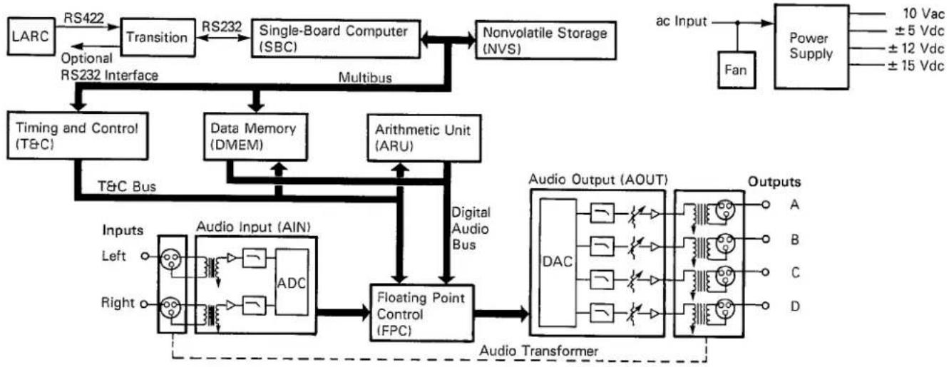
flowchart
graph TD
    A["LARC"] -->|RS422| B["Transition"]
    B -->|RS232| C["Single-Board Computer (SBC)"]
    C --> D["Nonvolatile Storage (NVS)"]
    D --> E["Power Supply"]
    E -->|10 Vac ±5 Vdc ±12 Vdc ±15 Vdc| F["Fan"]
    F --> G["ac Input"]
    G --> H["Timing and Control (T&C)"]
    H --> I["T&C Bus"]
    I --> J["Data Memory (DMEM)"]
    J --> K["Artithmetic Unit (ARU)"]
    K --> L["Floating Point Control (FPC)"]
    L --> M["Audio Output (AOUT)"]
    M --> N["Outputs"]
    O["Inputs Left Right"] --> P["Audio Input (AIN)"]
    P --> Q["ADC"]
    Q --> R["Floating Point Control (FPC)"]
    R --> M
    style O stroke-dasharray: 5 5
    style P stroke-dasharray: 5 5
    style Q stroke-dasharray: 5 5
    style R stroke-dasharray: 5 5
    style M stroke-dasharray: 5 5
    style N stroke-dasharray: 5 5
6.3.1 Lexicon Alphanumeric Remote Console (LARC)
The LARC communicates with the 224X mainframe through a shielded 50-ft 7-conductor cable (supplied — Lexicon no. 680-03525). Two of the conductors provide 10-Vdc power to the LARC, where it is filtered and regulated to 5 Vdc. The remaining five conductors form an RS-422 serial communications link between the LARC and the 224X mainframe. The LARC contains a microprocessor that (1) scans the switches, digitizes the slide pots, and sends
the information to the 224X; (2) receives alphanumeric and headroom data from the 224X and displays the data on the LEDs; (3) receives data for tape output from the 224X and generates frequency shift keyed (FSK) data; and (4) monitors FSK data from the tape input and sends the data to the 224X. All of these data communications with the 224X occur over the RS-422 serial link.
6.3.2 Transition Module
The Transition module serves as an interface between the 224X mainframe and the LARC. It receives 10-Vac power from the power supply, rectifies and filters it, and sends it to the LARC. It also takes RS-232 data from the SBC
module and level-converts it to RS-422 data for communications with the LARC. The Transition module accepts an optional RS-232 interface.
6.3.3 Single-Board Computer (SBC) Module
The SBC module is the 224X system controller. It contains the microprocessor that generates alphanumeric and headroom messages for display on the LARC, waits for user responses, and based on these responses, loads and modifies the reverberation and effects programs running on the digital processor (T&C, ARU, and DMEM modules).
In addition to the microprocessor, the SBC module contains volatile RAM memory for system use, ROM memory that holds part of the system software, an RS-232 serial interface used (through the Transition module) for communications with the LARC, and a multi-bus interface for communications with the rest of the boards in the system.
6.3.4 Nonvolatile Storage (NVS) Module
The NVS module provides the bulk of the ROM storage for the system. Although some system software is contained in ROMs in the SBC module, the remainder of the system software and the software for the T&C module are stored in ROMs on the NVS module. The 224X is updated by replacing ROMs on the NVS and SBC modules.
The NVS module also provides RAM memory storage with NiCad battery backup used to store all 224X memory registers. Data retention is in excess of three months. The storage batteries are maintained at full charge by a trickle charger that operates whenever the 224X is turned on. An on-board detection circuit monitors the ac mains power and places the memory in protected storage when a power outage is detected. When the system is powered up, the 224X logs on with all prior panel settings and register contents intact.
6.3.5 Timing and Control (T&C), Data Memory (DMEM), and Arithmetic Unit (ARU) Modules
The T&C, DMEM, and ARU modules provide the basic digital signal processing and data storage capabilities to allow the 224X to synthesize reverberant sound in quad, stereo, or monophonic formats. The T&C module has RAM storage for the signal-processing programs, from which (using the clock provided
by the SBC module as a reference) it generates all the clocks and control signals for the system. The ARU module performs all mathematical calculations needed, and the DMEM module provides necessary address calculations and data storage.
6.3.6 Audio Input (AIN), Audio Output (AOUT), and Floating Point Converter (FPC) Modules
In the AIN module, input analog signals are transformer-coupled, gain-conditioned, and filtered before digitization. The input digitizer converts each analog signal into a digital representation (analog-to-digital conversion [ADC]) that the FPC module transfers to the digital signal processor as a 16-bit word.
The FPC module is also used to process output data to the digital-to-analog converter (DAC) contained in the AOUT module. The output DAC circuitry reconstructs the analog information, which is then low-pass filtered and transformer coupled to the output channels.
Service
6.3.7 Audio Transformer Module
The Audio Transformer module contains four audio output line transformers (one for each output). Additional functions include RFI filtering and interface of all input and output lines to their respective XLR-3 connectors. The
Audio Transformer module interfaces to the connector backplane through a 16-conductor ribbon cable. Audio input line transformers are on the AIN module, not on the Audio Transformer module.
6.3.8 Power Supplies
The mains circuit for the 224X uses a tapped dual primary transformer that provides 100-, 120-, 220-, or 240-Vac (nominal) operation — voltage changeover switches are used to select operating voltage. Procedures for setting operating voltage are discussed in Sec. 2.1. This supply is switched on both sides of the line. A primary fuse is provided on the rear panel of the mainframe chassis after the RFI filter unit. Fan power is maintained at either 100 or 120
Vac, regardless of the switch settings, by connecting the fan across one of the primaries.
The 224X power supply produces three pairs of regulated dc voltages for the main processor, and one ac voltage provided to the Transition module for the LARC. Each pair of regulated supplies has its own fused center-tapped secondary. Table 6.1 lists the power supplies, their capacities, and fuse locations.
Table 6.1. Power Supplies and Fuses.
| Power Supply | Voltage | Current Rating | Fuse Location | Fuse Rating |
| PS1/PS3 | +5 Vdc | 10 A | Fuse board, +/−5 V | 15 A slow |
| PS1/PS3 | −5 Vdc | 250 mA | Fuse board, +/−5 V | 15 A slow |
| −5 Vdc | 250 mA | Fuse board, −5 Vdc | 2.5 A slow | |
| PS2 | +12 Vdc | 1.25 A | Fuse board, +/−12 V | 3 A slow |
| PS3 | −12 Vdc | 150 mA | Fuse board, +/−12 V | 3 A slow |
| PS2 | +15 Vdc | 750 mA | Fuse board, +/−15 V | 2 A slow |
| PS2 | −15 Vdc | 750 mA | Fuse board, +/−15 V | 2 A slow |
| Transition | 10 Vac | 500 mA | Fuse board, VISO | 2 A slow |
| LARC (internal) | +5 Vdc | 1 A | Electronics board | 1 A, 32 V fast |
Power Supply Verification. Table 6.2 lists the test points and voltage tolerances for each power supply. (The mainframe chassis can be used for ground unless otherwise noted.) Figures 6.2 and 6.3 show interior views of the 224X mainframe and the locations of the power supply test points.

Table 6.2. Test Point Locations for Power Supplies.
| Number | Supply (Vdc) | Limits (Vdc) | Location description |
| 1 | +5 | 4.85-5.15 | SBC module; U16, pin 16: left front-most IC; left front IC pin; verify left LED lit on NVS module |
| 2 | -5 | 4.75-5.25 | SBC module; J72 at the rear and right of U16** |
| 3 | +12 | 11.4-12.6 | SBC module; R8 front lead; 2.7-Kohm, 1/4-W resistor, left of U15; verify center LED lit on NVS module |
| 4 | -12 | 11.4-12.6 | SBC module; R4 front lead; 270-ohm, 1/2-W resistor, right of U15 |
| 5 | +15 | 14.75-15.25 | AIN module; +15 = test point, ground to test point |
| 6 | -15 | 14.75-15.25 | AIN module; -15 = test point, ground to test point |
| 7 | +7 | 6.3-7.7 | AIN module; +7 = test point, ground to test point |
| 8 | -7 | 6.3-7.7 | AIN module; -7 = test point, ground to test point |
| 9 | +7 | 6.3-7.7 | AOUT module; +7 = test point, ground to test point |
| 10 | -7 | 6.3-7.7 | AOUT module; -7 = test point, ground to test point |
| 11 | +10 | 8-14 | LARC connector; pin 5 = test point, ground to pin 9 |
| 12 | +5 | Transition module | |
| -12 | pin 2 (red) = +5 | ||
| +12 | pin 6 (orange) = -12 | ||
| pin 1 (purple) = +12 |
*See Figs. 6.2 and 6.3 for locations.
**To access this test point, turn off the 224X and loosen the SBC module from its backplane connector, connect a test lead to the J72 test point, and then reinsert the SBC module into the backplane.
Service
Fig. 6.2. 224X Mainframe Interior — Front View.

Fig. 6.3. 224X Mainframe Interior — Top View.


Indicates power supply test point; see Sec. 6.3.8.
Service
6.4
Troubleshooting
If the power-up diagnostic programs indicate problems that require more extensive troubleshooting procedures, before proceeding, first verify the integrity of the power supplies — see Sec. 6.3.8.
6.4.1 Mainframe or LARC Does Not Power Up
If the 224X mainframe does not power up (as indicated by an unlit front-panel light), first check the ac power cord to ensure that it is securely plugged into the rear panel and service outlet. Next, check the rear-panel mains fuse, and using a voltmeter, neon test light, or common lamp, verify that the service outlet is live and that the line voltage is correct (see Sec. 2.1). If the line voltage to the unit is correct, unplug the 224X and refer the problem to a qualified service technician (who can check the internal voltage changeover switches, fuses, and cable harnesses), or refer the problem to Lexicon.
Note: In addition to the rear-panel mains fuse, the 224X has eight internal power supply fuses (three pairs of fuses between
the power transformer secondaries and the three regulated power supplies, one for the -5-V output of PS1, and one for the LARC power supply). A blown internal fuse usually indicates a problem — if you suspect a failed internal fuse, consult a qualified service technician. For reference, Sec. 6.3 lists and describes the power supply fuses, and Fig. 6.3 shows the fuse locations.
If the mainframe powers up but the LARC does not, check the remote cable connecting the LARC to the mainframe. If the cable and connections are intact, the LARC's internal fuse or the Transition module fuse (labeled VISO on the Fuse board) may be blown — refer this problem to a qualified service technician.
6.4.2 Unit Gives Improper Display or Error Message
If an unintelligible display appears in the window of the LARC, the display fails to show program entries, or an error message appears, the 224X's processor may be malfunctioning
(see Sec. 6.5). Refer the problem to a qualified service technician. Note: Some error messages indicate problems that do not compromise performance — see Sec. 6.5.
6.4.3 Unit Does Not Pass Audio or Distorts Audio
Check Cables. Verify that all audio cables are securely plugged into proper jacks. Check for intermittent contacts, and if connections are good, look for discontinuity and shorts between conductors while flexing the cable.
in the 224X. Refer problems to a qualified service technician, or return the unit to Lexicon.
Check Other Sound Equipment in System. If all cables check out, verify that the problem is in the 224X by connecting together the 224X input and output cables. If audio now passes through the system, the problem resides
Isolating Problems in the Audio Section. The 224X is designed so that a qualified technician can perform certain tests to isolate audio-processing problems if all other diagnostics cannot locate the problem. Figure 6.4 shows the approach to follow for these tests; note that this approach requires three main tests: (1) running a delay-line diagnostic pro-
gram, (2) removing the LARC, and (3) conducting the self test. Please make careful notes of the results of these tests to help clearly identify problems when communicating with Lexicon.

flowchart
graph TD
    A["224X<br>Won't Pass<br>or Distorts<br>Audio"] --> B{Does Diagnostic Delay
Sound OK?}
    B -->|YES| C{Does Removing LARC
Correct Problem?}
    B -->|NO| D{Does Audio
Sound OK in
Self Test?}
    C -->|YES| E["Problem is<br>in LARC<br>or SBC<br>module"]
    C -->|NO| F["Problem is<br>in DMEM,<br>T&C, or<br>ARU modules"]
    D -->|NO| G["Problem is<br>in FPC,<br>AIN, or<br>AOUT modules"]
    E --> H["Call Lexicon<br>for assistance"]
    F --> H
    G --> H
    H --> I["End"]
Service
The first test is to run a delay-line diagnostic program. Follow the instructions described in Sec. 2.3 to activate the 0.5-second Delay diagnostic program. Feed an audio source into both Right and Left inputs, and listen carefully to the audio outputs, noting the sound quality of each of the four channels. Remember that the delay-line programs pass the Left input to outputs A and D and the Right input to outputs C and B. Also check to see that the headroom display on the LARC is functioning correctly. If the audio sounds good, then proceed to the LARC removal test. If the audio still sounds bad, proceed to the self test.
The second test is to remove the LARC. First, return the 224X to normal operation by pressing numeric-select key 2. Disconnect the LARC cable from the mainframe. Feed an audio source into both Right and Left inputs, and listen carefully to the audio outputs, noting the sound quality of each of the four channels. If the audio sounds good, a faulty LARC or SBC module is indicated. If the audio
sounds bad, a faulty T&C, DMEM, or ARU module is indicated. Call Lexicon for further assistance.
The third test is called self test; it can be performed with or without the LARC connected to the mainframe. To perform this test, turn off the 224X. Remove the front panel and board retention bar on the main frame. Extract the T&C, DMEM, and ARU modules from their backplane connectors. Turn on the 224X by pressing the POWER switch. Feed an input source into both Right and Left inputs, and listen carefully to the audio outputs, noting the sound quality of each of the four channels. This test passes the Left input to outputs A and B, and the Right input to outputs C and D. Note that during this test the LARC display is meaningless. If the audio sounds good, a faulty T&C, DMEM, or ARU module is indicated. If the audio sounds bad, a faulty FPC, AIN, or AOUT module is indicated. Call Lexicon for further assistance.
6.4.4 Unit Cannot Recall User-Modified Programs
The 224X stores user-modified programs (presets) in random access memory (RAM) registers. The contents of RAM memory registers normally disappear when power is shut off; however, the 224X employs a NiCad battery pack to provide continuous power to the registers. If the unit has not been used for a while or is several years old, the battery pack may be too weak to power the registers, which would explain a memory loss. If you
suspect a weak battery, leave the 224X turned on for 24 hours; if the battery remains dead, have a qualified service technician replace it.
Note: Be sure the effect was actually stored; a one-time loss of one or more memory registers that cannot be repeated may be caused by transient interference that penetrates the 224X's RFI and power supply filtering.
Diagnostic Programs
During the first 25 seconds of power-up, the 224X runs a series of internal, self-testing diagnostic programs that check major components. If an error is detected, an error message appears in the LARC's display window. Error messages look like this:
DIAG ERROR
TYPE E32
C = 5 5 B = 5 4 BIT 0 ADDR = 0 0 0 0
To continue through a test, press numeric-select key 1. If the test finds more errors, additional error messages are displayed. To help clearly identify a problem or to arrange for expeditious field servicing, note these messages when communicating with Lexicon or with a service technician. Write down all diagnostic messages on a copy of the log provided. Continue to press numeric-select key 1 until all messages are displayed. After all errors are found and displayed, the 224X will attempt to return to normal operation.
Log for Diagnostic Messages*
| Error Type | C | B | BIT | ADDR |
The diagnostic programs display the following error types:
| Error Type* | Cause of Error |
| E0X | SBC ROM checksum |
| E1X | SBC RAM |
| E2X, E3X, E4X | T&C (may also be DMEM) |
| E5X, E6X, E7X, E8X | ARU (may also be T&C or DMEM) |
| E91, E92, E95, E96 | DMEM |
| H0X, H2X | NVS ROM checksum |
| H1X | NVS RAM |
| H2F, H10 | NVS card missing |
*Where X is from 0 to 9 or from A to F.
*Use a photocopy of this log to record diagnostic messages.
To exit from these self-testing diagnostics and error messages and attempt to return to normal operation, press numeric-select key 2.
Note: Some errors do not compromise performance. For example, a problem may occur in the error detection circuits themselves or in a low-order bit that is not easily audible. In addition, errors can occur that affect the sound of the 224X but do not display error messages; these can be isolated using the procedures outlined in Sec. 6.4, Troubleshooting.
How To Load Diagnostic Programs. In addition to the self-testing programs that run during power-up, the 224X has two groups of diagnostic programs accessible through the LARC: LARC Tests and Mainframe Tests.
These diagnostic programs are organized into two menus. To enter the LARC diagnostic test mode, after the 224X has powered up and resumed normal operation (about 25 seconds after the POWER or RESET buttons have been pressed), press PAGE and while holding it
down, press PROG. To scroll through the menus, press PAGE and to load a displayed program, press PROG.
Caution: After resetting the 224X mainframe, DO NOT press any of the numeric-select keys until normal operation resumes — pressing a numeric-select key could erase the memory registers.
Table 6.3 shows how the diagnostic programs are organized and how they are loaded, and Table 6.4 gives a description of how each program functions.
Service
Table 6.3. 224X Diagnostic Program Menus.
| To Scroll Through Diagnostic Programs, Press PAGE | To Activate Diagnostic Programs, Press PROG | To Exit, Press | |
| Menu Options | |||
| LARC Tests | |||
| EXIT TEST | PROG | ||
| SLIDER TEST | PROG | ||
| BUTTON TEST | PROG | ||
| DISPLAY TEST | PROG | ||
| TAPEOUT TEST | VAR | ||
| DROPOUT TEST | PROG | ||
| SERIAL TEST | PROG | ||
| VOLTAGE TEST | PROG | ||
| MAINFRAME TEST(Exit to Mainframe Test Menu) | PROG | ||
| Mainframe Tests | |||
| 1 RESTART | * | ||
| 2 QUICK EXIT | ** | ||
| 3 ARU SIGNATURE | PROG | ||
| 4 ARU TESTS | |||
| 5 NVS STROBE | PROG | ||
| 6 FPC SIGNATURE | PROG | ||
| 7 ZERO DELAY | PROG | ||
| 8 .5 S DELAY | PROG | ||
| 9 TEST ALL | * | ||
| 0 NVS INITIALIZATION | ** |
* After execution, performs power-up diagnostics and returns to normal operation.
** After execution, returns directly to normal operation.
†After execution, returns directly to Mainframe menu.

| Table 6.4. Diagnostic Programs. | Program | Description |
| LARC Tests | EXIT | Returns to normal operation |
| SLIDER | tests slider action through all positions; each slider should pass without interruption through 256 positions (0 to 255) | |
| BUTTON | tests button functionality; position of last button pushed and last button released is displayed | |
| DISPLAY | lights all LEDs; pressing PAGE steps through three displays | |
| TAPEOUT | generates a 4800-Hz test tone. Record a tape with this tone for the DROPOUT test — Note: Press VAR to exit | |
| DROPOUT | monitors tape input for a stable 4800-Hz tone; start tape at beginning of tone, then execute — display should stabilize | |
| SERIAL | transmits a series of bytes to the mainframe and displays returned results | |
| VOLTAGE | displays LARC power supply voltage — should be stable between 4.8 and 5.2 (048-052). Low voltage could indicate excessive cable power drop and need for remote power pack | |
| MAINFRAME | switches to mainframe diagnostics menu; to scroll through diagnostic programs, press PAGE ... PAGE | |
| Mainframe Tests | 1 RESTART | restarts self-testing power-up diagnostics and returns to normal operation |
| 2 QUICK EXIT | exits directly to normal operation | |
| 3 ARU SIGNAT | generates signature analysis signals; for use by service personnel to test the ARU module | |
| 4 ARU TESTS | runs a quick test of the ARU module and returns to menu | |
| 5 NVS STROBE | generates analysis signals; for use by service personnel to test the NVS module | |
| 6 FPC SIGNAT | generates analysis signals; for use by service personnel to test the FPC module | |
| 7 ZERO DELAY | loads a 0-second delay-line program for setting input and output levels; Left input passes to outputs A and C, and Right input passes to outputs B and D | |
| 8 .5 S DELAY | loads a 0.5-second delay-line program for setting input and output levels; Left input passes to outputs A and C, and Right input passes to outputs B and D | |
| 9 TEST ALL | runs all diagnostic tests including additional NVS tests and returns to normal operation | |
| 0 NVS INIT | initializes the NVS module and returns to menu;Caution: erases all memory registers |
Service
6.6
Module Exchange Program
If a defective module is clearly identified, Lexicon can usually provide a repair/exchange module within 24 hours in advance of receipt of the defective module. If a fast turnaround is required, Lexicon can ship a module by Federal Air Express or other expedited air service, resulting in 24-hour delivery if the customer is near a major airport. For this service, the customer is expected to pay shipping charges.
Important: When shipping a module for repair or exchange, always call Lexicon before packaging it for shipment; Lexicon ships modules in reusable static protective bags with appropriate packing materials — use these materials or procure new materials from Lexicon. Lexicon is not liable for damage resulting from unauthorized shipping procedures.
6.7
Returning Units for Service
If the 224X or LARC must be returned to Lexicon or a designated facility for service, Lexicon assumes no responsibility for the units in shipment from customer to factory, whether in or out of warranty. All shipments must be well packed (using the original packing materials, if possible), properly insured, and consigned to a reliable agent, such as UPS or Federal Air Express. If original packing materials are not available, please procure a new packing kit from Lexicon.
When returning equipment for service, include the following information:
Always consult with Lexicon before returning a unit to determine a problem's extent and the most efficient method of handling it.
Name (and Company Name)
Address
City, State, ZIP
Telephone Number
Description of Problem
Desired Return Date
Preferred Method of Shipment
Please include a note describing conversations with Lexicon personnel, and give the name and telephone number of the person directly responsible for maintaining the equipment. Do NOT include accessories, such as power cords or manuals.
6.8
Ordering Parts
Replacement parts can be ordered from:
Lexicon, Inc.
60 Turner Street Waltham, MA 02154 USA (617) 891-6790
Telex 923 468
Attn: Customer Service
Parts are shipped FOB Waltham, MA. Customers are charged the price in effect at the time of the order. Lexicon welcomes parts quotations any time during business hours.
When ordering parts, give the following information:
1
Part number and I.D., if available
2
Item description
3
Quantity desired
4
224X serial number.
Specifications
7.1
| Specifications | |
| Programs | 18 programs, 59 preset variations, expandable through software updates. |
| Register storage | 36 registers (nonvolatile) divided into 10 user-labeled banks with from 1 to 10 registers per bank. |
| Reverberation time | Adjustable in two bands from approximately 0.2 to 70 seconds (program-dependent). |
| Additional controls | Four mode-select buttons (BANK, PROG, VAR, REG) used with ten numeric-select buttons (1 to 0); tape storage and register control buttons (TAPE, STO); a page-select button (PAGE); three auxiliary control buttons (MUTE, PARAM, 2nd F); six sliders for smooth control of up to 42 parameters per program with associated display-select buttons. |
| LARC display | Two lines of 12 alphanumeric LEDs for interactive menu-driven display; additional line of 24 alphanumeric LEDs (six groups of four for each slider); dual 16-position LED headroom indicator (calibrated -24 to +12 dBm plus overload). |
| Mainframe controls | Power on and indicator light; system reset; Left and Right input level adjustments; A, B, C, D output level adjustments. |
| Frequency response | 20 Hz to 15 kHz +/-1.5 dB; 20 Hz to 12 kHz +/-0.5 dB. |
| Dynamic range* | Reverberant mode84 dB typical, 81 dB minimum relative to Reference Level, 20 Hz to 20 kHz noise bandwidth for all reverb times from 0 to 10 seconds.Nonreverberant mode90 dB typical, 86 dB minimum, 20 Hz to 20 kHz noise bandwidth. |
| Total harmonic distortion (THD) and noise* | 0.04% typical, 0.07% maximum at Reference Level for all reverberation times between 0 and 35 seconds. |
| Interchannel Crosstalk | -55 dB at 1 kHz. |
| Inputs | Two, balanced and transformer isolated; impedance: 20 kilohm; maximum level adjustable: +8 to +18 dBm. |
| Outputs | Four, balanced and transformer isolated; impedance: 90 ohm; maximum level adjustable: +8 to +18 dBm; power-on muting. |
| LARC cable | 50-ft extraflexible cable; cables can be linked — up to 1000 ft possible with optional remote power source. |
*Reference Level is set using the zero delay-line diagnostic test program with input level adjustment set just below level at which the +12 dB LED lights with a 1-kHz tone at the input and with output sensitivity set to produce +12 dBm with a 600-ohm load. For reverberant mode, measurements are made using the Concert Hall program with the Mode Enhancement toggle off; for nonreverberant mode, measurements are made using the zero delay-line diagnostic test program.
Specifications
| Power | MainframeNominal: 100, 120, 220, 240 Vac (-10%, +5%) switch-selectable; 50 to 60 Hz; 150 W.LARCNormally powered through 224X mainframe; miniature jackaccepts optional remote power supply for distances greater than100 ft - 10 to 20 Vdc or 10 to 20 Vac, 6.25 W. |
| RFI shielding | ac power connector, audio connectors, and console cable areRFI shielded; complies with FCC limits for Class A computingdevice. |
| Protection | Mains fused; secondaries fused; voltage crowbar and/or currentlimiting; thermal protection. |
| Connectors | MainframePower: standard IEC 3-pinAudio: XLR-3LARC: DE-9Optional Automation Interface: DB-25LARCMainframe Cable: DE-9Cassette Interface Cable: DIN-5 180°Optional Remote Power Supply: standard dc |
| Serviceability | Field serviceable; each major assembly removable. |
| Diagnostic programs | Control and display via LARC; automatic at power-up or reset. |
| Cooling | Convection-cooled power supply; forced-air cooling of logiccards. |
| Environment | Operating: 0 to +35°C; storage: -30 to +75°C; relative humidity: 95% maximum (without condensation). |
| Size | MainframeStandard 19-inch rack mount: 19"w x 7"h x 15"d (483 x 178 x381 mm).LARC5.9"w x 9.5"h x 3.2"d (150 x 242 x 82 mm). |
| Weight | Mainframe34 lbs (15.5 kg); 40 lbs (19 kg) shipping.LARC1.9 lbs (0.9 kg); 7 lbs (3.2 kg) shipping. |
| Cassette interface | 600-baud FSK with Hamming error detection/correction; used tostore any or all of the nonvolatile register banks; DIN-5 180°connector. |
| Automation interface | Optional RS-232C serial interface. |
Warranty
8.1
Limited Warranty
Lexicon warrants each Model 224X with LARC to be free from defects in material and workmanship under normal use and service for one year. This warranty begins on the date of delivery to the purchaser or his authorized agent or carrier. During the warranty period, Lexicon will repair, or at its option replace, at no charge, components that prove to be defective provided that the equipment is returned, shipping prepaid, to Lexicon's factory or designated service facility.
The warranty is null and void under the following conditions:
1
Abuse, neglect, alteration, or repair by unauthorized personnel
2
Damage caused by improper use or operation from an incorrect power source
3
Damage caused by accident, act of God, war, or civil insurrection.
Lexicon shall not be responsible for loss or damage, direct or consequential, resulting from machine failure or the inability of the product to perform. Lexicon shall not be responsible for damage or loss during shipment to or from its factory or designated service facility.
Lexicon reserves the right to make changes or improvements in the design or construction of the machine without obligation to make such changes or improvements in the purchaser's machine.
No equipment may be returned under this warranty without prior authorization from Lexicon. Shipments must be packed in authorized Lexicon packing material, fully insured, and prepaid.
This warranty is in lieu of all other warranties, expressed or implied, and of any other liabilities on Lexicon's part; in addition, Lexicon does not assume or authorize anyone to make any warranty or assume any liability not strictly in accordance with the above.
9 Register Log

| Use photocopies or reprints of the form on this page to log the contents of your registers. Organize completed log forms by register number and insert them behind the divider entitled "Log." | ||||||
| Preset Log | ||||||
| Bank No. | Bank Title | |||||
| Register No. | Register Title | |||||
| Engineer | Date | |||||
| Derived from program | ||||||
| Page | Variable Parameter Settings | |||||
| 1 | ||||||
| 2 | ||||||
| 3 | ||||||
| 4 | ||||||
| 5 | ||||||
| 6 | ||||||
| 7 | ||||||
| 1 | 2 | 3 | 4 | 5 | 6 | |
| Sliders | ||||||
| Parameter Toggles:[] Dynamic Decay[] Mode Enhancement[] Decay Optimization | ||||||
| Notes | ||||||
Variation Presets
This section contains the preset parameter values for all program variations in the latest version of 224X software. Tables are organized by bank and program.


Variation Presets Halls
| Concert Hall Variation 1 Presets | Page | Variable Parameter Presets | |||||
| 1 | LF Decay | Mid Decay | Crossover | Treble Decay | Depth | Predelay | |
| 3.0 sec | 2.0 sec | 720 Hz | 6.30 kHz | 33 | 24.0 msec | ||
| 2 | LF Stop Decay | Mid Stop Decay | Chorus | HF Bandwidth | Diffusion | Definition | |
| 3.0 sec | 3.0 sec | 50 | 9.00 kHz | 25 | 00 | ||
| 3 | Preecho Level 1 | Preecho Level 2 | Preecho Level 3 | Preecho Level 4 | |||
| 00 | 00 | 00 | 00 | Inactive | Inactive | ||
| 4 | Preecho Delay 1 | Preecho Delay 2 | Preecho Delay 3 | Preecho Delay 4 | Fine Predelay | Fine Predelay | |
| 5.00 msec | 9.75 msec | 17.5 msec | 25.0 msec | 0.36 msec | 10.2 msec | ||
| 1 | 2 | 3 | 4 | 5 | 6 | ||
| Sliders | |||||||
| Parameter Toggles: Dynamic Decay [0] Mode Enhancement [1] Decay Optimization [0] | |||||||
| Concert Hall Variation 2 Presets | Page | Variable Parameter Presets | |||||
| 1 | LF Decay | Mid Decay | Crossover | Treble Decay | Depth | Predelay | |
| 1.7 sec | 1.7 sec | 720 Hz | 6.30 kHz | 33 | 30.0 msec | ||
| 2 | LF Stop Decay | Mid Stop Decay | Chorus | HF Bandwidth | Diffusion | Definition | |
| 3.0 sec | 3.0 sec | 50 | 9.00 kHz | 15 | 00 | ||
| 3 | Preecho Level 1 | Preecho Level 2 | Preecho Level 3 | Preecho Level 4 | |||
| 18 | 20 | 14 | 17 | Inactive | Inactive | ||
| 4 | Preecho Delay 1 | Preecho Delay 2 | Preecho Delay 3 | Preecho Delay 4 | Fine Predelay | Fine Predelay | |
| 5.00 msec | 9.75 msec | 17.5 msec | 25.0 msec | 0.36 msec | 10.2 msec | ||
| 1 | 2 | 3 | 4 | 5 | 6 | ||
Sliders
Parameter Toggles: Dynamic Decay [0] Mode Enhancement [1]
Decay Optimization [1]

| Concert Hall Variation 3 Presets | Page | Variable Parameter Presets | |||||
| 1 | LF Decay | Mid Decay | Crossover | Treble Decay | Depth | Predelay | |
| 3.8 sec | 2.4 sec | 720 Hz | 6.30 kHz | 33 | 24.0 msec | ||
| 2 | LF Stop Decay | Mid Stop Decay | Chorus | HF Bandwidth | Diffusion | Definition | |
| 3.0 sec | 3.0 sec | 50 | 9.00 kHz | 01 | 00 | ||
| 3 | Preecho Level 1 | Preecho Level 2 | Preecho Level 3 | Preecho Level 4 | |||
| 00 | 00 | 00 | 00 | Inactive | Inactive | ||
| 4 | Preecho Delay 1 | Preecho Delay 2 | Preecho Delay 3 | Preecho Delay 4 | Fine Predelay | Fine Predelay | |
| 5.00 msec | 9.75 msec | 17.5 msec | 25.0 msec | 0.36 msec | 10.2 msec | ||
| 1 | 2 | 3 | 4 | 5 | 6 | ||
| Sliders | |||||||
| Parameter Toggles: Dynamic Decay [0] Mode Enhancement [1] Decay Optimization [1] | |||||||
| Concert HallVariation 4 Presets | Page | Variable Parameter Presets | |||||
| 1 | LF Decay | Mid Decay | Crossover | Treble Decay | Depth | Predelay | |
| 3.0 sec | 3.0 sec | 720 Hz | 6.30 kHz | 33 | 42.0 msec | ||
| 2 | LF Stop Decay | Mid Stop Decay | Chorus | HF Bandwidth | Diffusion | Definition | |
| 3.0 sec | 3.0 sec | 50 | 7.50 kHz | 01 | 00 | ||
| 3 | Preecho Level 1 | Preecho Level 2 | Preecho Level 3 | Preecho Level 4 | |||
| 45 | 37 | 25 | 18 | Inactive | Inactive | ||
| 4 | Preecho Delay 1 | Preecho Delay 2 | Preecho Delay 3 | Preecho Delay 4 | Fine Predelay | Fine Predelay | |
| 7.00 msec | 8.75 msec | 18.5 msec | 34.0 msec | 0.36 msec | 10.2 msec | ||
| 1 | 2 | 3 | 4 | 5 | 6 | ||
| Sliders | |||||||
| Parameter Toggles: Dynamic Decay [0] Mode Enhancement [1] Decay Optimization [1] | |||||||
| Concert Hall Variation 5 Presets | Page | Variable Parameter Presets | |||||
| 1 | LF Decay | Mid Decay | Crossover | Treble Decay | Depth | Predelay | |
| 7.5 sec | 5.7 sec | 720 Hz | 6.30 kHz | 33 | 24.0 msec | ||
| 2 | LF Stop Decay | Mid Stop Decay | Chorus | HF Bandwidth | Diffusion | Definition | |
| 3.0 sec | 3.0 sec | 50 | 9.00 kHz | 25 | 00 | ||
| 3 | Preecho Level 1 | Preecho Level 2 | Preecho Level 3 | Preecho Level 4 | |||
| 00 | 00 | 00 | 00 | Inactive | Inactive | ||
| 4 | Preecho Delay 1 | Preecho Delay 2 | Preecho Delay 3 | Preecho Delay 4 | Fine Predelay | Fine Predelay | |
| 5.00 msec | 9.75 msec | 17.5 msec | 25.0 msec | 0.36 msec | 10.2 msec | ||
| 1 | 2 | 3 | 4 | 5 | 6 | ||
| Sliders | |||||||
| Parameter Toggles: Dynamic Decay [0] Mode Enhancement [1] Decay Optimization [1] | |||||||
| Concert Hall Variation 6 Presets | Page | Variable Parameter Presets | |||||
| 1 | LF Decay | Mid Decay | Crossover | Treble Decay | Depth | Predelay | |
| 1.7 sec | 1.7 sec | 720 Hz | 6.30 kHz | 33 | 30.0 msec | ||
| 2 | LF Stop Decay | Mid Stop Decay | Chorus | HF Bandwidth | Diffusion | Definition | |
| 5.7 sec | 5.7 sec | 50 | 9.00 kHz | 15 | 00 | ||
| 3 | Preecho Level 1 | Preecho Level 2 | Preecho Level 3 | Preecho Level 4 | |||
| 18 | 20 | 14 | 17 | Inactive | Inactive | ||
| 4 | Preecho Delay 1 | Preecho Delay 2 | Preecho Delay 3 | Preecho Delay 4 | Fine Predelay | Fine Predelay | |
| 5.00 msec | 9.75 msec | 17.5 msec | 25.0 msec | 0.36 msec | 10.2 msec | ||
| 1 | 2 | 3 | 4 | 5 | 6 | ||
| Sliders | |||||||
| Parameter Toggles: Dynamic Decay [1] Mode Enhancement [1] Decay Optimization [1] | |||||||


| Concert Hall Variation 7 Presets | Page | Variable Parameter Presets | |||||
| 1 | LF Decay | Mid Decay | Crossover | Treble Decay | Depth | Predelay | |
| 5.7 sec | 5.7 sec | 720 Hz | 6.30 kHz | 33 | 24.0 msec | ||
| 2 | LF Stop Decay | Mid Stop Decay | Chorus | HF Bandwidth | Diffusion | Definition | |
| 1.7 sec | 1.7 sec | 50 | 9.00 kHz | 25 | 00 | ||
| 3 | Preecho Level 1 | Preecho Level 2 | Preecho Level 3 | Preecho Level 4 | |||
| 00 | 00 | 00 | 00 | Inactive | Inactive | ||
| 4 | Preecho Delay 1 | Preecho Delay 2 | Preecho Delay 3 | Preecho Delay 4 | Fine Predelay | Fine Predelay | |
| 5.00 msec | 9.75 msec | 17.5 msec | 25.0 msec | 0.36 msec | 10.2 msec | ||
| 1 | 2 | 3 | 4 | 5 | 6 | ||
| Sliders | |||||||
| Parameter Toggles: Dynamic Decay [1] Mode Enhancement [1] Decay Optimization [1] | |||||||
| Bright Hall Variation 1 Presets | Page | Variable Parameter Presets | |||||
| 1 | LF Decay | Mid Decay | Crossover | Treble Decay | Depth | Predelay | |
| 3.0 sec | 2.0 sec | 720 Hz | 6.30 kHz | 33 | 24.0 msec | ||
| 2 | LF Stop Decay | Mid Stop Decay | Chorus | HF Bandwidth | Diffusion | Definition | |
| 3.0 sec | 3.0 sec | 50 | 19.0 kHz | 44 | 00 | ||
| 3 | Preecho Level 1 | Preecho Level 2 | Preecho Level 3 | Preecho Level 4 | |||
| 00 | 00 | 00 | 00 | Inactive | Inactive | ||
| 4 | Preecho Delay 1 | Preecho Delay 2 | Preecho Delay 3 | Preecho Delay 4 | Fine Predelay | Fine Predelay | |
| 5.00 msec | 19.0 msec | 0.00 msec | 1.00 msec | 0.75 msec | 0.50 msec | ||
| 1 | 2 | 3 | 4 | 5 | 6 | ||
| Sliders | |||||||
| Parameter Toggles: Dynamic Decay [0] Mode Enhancement [1] Decay Optimization [1] | |||||||
| Bright Hall Variation 2 Presets | Page | Variable Parameter Presets | |||||
| 1 | LF Decay | Mid Decay | Crossover | Treble Decay | Depth | Predelay | |
| 1.7 sec | 1.7 sec | 720 Hz | 6.30 kHz | 33 | 30.0 msec | ||
| 2 | LF Stop Decay | Mid Stop Decay | Chorus | HF Bandwidth | Diffusion | Definition | |
| 3.0 sec | 3.0 sec | 50 | 9.00 kHz | 25 | 00 | ||
| 3 | Preecho Level 1 | Preecho Level 2 | Preecho Level 3 | Preecho Level 4 | |||
| 18 | 20 | 14 | 17 | Inactive | Inactive | ||
| 4 | Preecho Delay 1 | Preecho Delay 2 | Preecho Delay 3 | Preecho Delay 4 | Fine Predelay | Fine Predelay | |
| 5.00 msec | 9.75 msec | 17.5 msec | 25.0 msec | 6.36 msec | 10.2 msec | ||
| 1 | 2 | 3 | 4 | 5 | 6 | ||
| Sliders | |||||||
| Parameter Toggles: Dynamic Decay [0] Mode Enhancement [1] Decay Optimization [1] | |||||||
| Bright Hall Variation 3 Presets | Page | Variable Parameter Presets | |||||
| 1 | LF Decay | Mid Decay | Crossover | Treble Decay | Depth | Predelay | |
| 3.8 sec | 2.4 sec | 720 Hz | 6.30 kHz | 33 | 24.0 msec | ||
| 2 | LF Stop Decay | Mid Stop Decay | Chorus | HF Bandwidth | Diffusion | Definition | |
| 3.0 sec | 3.0 sec | 50 | 19.0 kHz | 01 | 00 | ||
| 3 | Preecho Level 1 | Preecho Level 2 | Preecho Level 3 | Preecho Level 4 | |||
| 00 | 00 | 00 | 00 | Inactive | Inactive | ||
| 4 | Preecho Delay 1 | Preecho Delay 2 | Preecho Delay 3 | Preecho Delay 4 | Fine Predelay | Fine Predelay | |
| 5.00 msec | 19.0 msec | 0.00 msec | 1.00 msec | 0.75 msec | 0.50 msec | ||
| 1 | 2 | 3 | 4 | 5 | 6 | ||
| Sliders | |||||||
| Parameter Toggles: Dynamic Decay [0] Mode Enhancement [1] Decay Optimization [1] | |||||||
| Bright Hall Variation 4 Presets | Page | Variable Parameter Presets | |||||
| 1 | LF Decay | Mid Decay | Crossover | Treble Decay | Depth | Predelay | |
| 3.0 sec | 3.0 sec | 720 Hz | 6.30 kHz | 33 | 42.0 msec | ||
| 2 | LF Stop Decay | Mid Stop Decay | Chorus | HF Bandwidth | Diffusion | Definition | |
| 3.0 sec | 3.0 sec | 50 | 7.50 kHz | 37 | 00 | ||
| 3 | Preecho Level 1 | Preecho Level 2 | Preecho Level 3 | Preecho Level 4 | |||
| 45 | 37 | 25 | 18 | Inactive | Inactive | ||
| 4 | Preecho Delay 1 | Preecho Delay 2 | Preecho Delay 3 | Preecho Delay 4 | Fine Predelay | Fine Predelay | |
| 7.00 msec | 8.00 msec | 24.0 msec | 34.0 msec | 0.75 msec | 0.50 msec | ||
| 1 | 2 | 3 | 4 | 5 | 6 | ||
Sliders
Parameter Toggles: Dynamic Decay [0] Mode Enhancement [1] Decay Optimization [1]
| Bright Hall Variation 5 Presets | Page | Variable Parameter Presets | |||||
| 1 | LF Decay | Mid Decay | Crossover | Treble Decay | Depth | Predelay | |
| 7.5 sec | 5.7 sec | 720 Hz | 6.30 kHz | 33 | 24.0 msec | ||
| 2 | LF Stop Decay | Mid Stop Decay | Chorus | HF Bandwidth | Diffusion | Definition | |
| 3.0 sec | 3.0 sec | 50 | 19.0 kHz | 44 | 00 | ||
| 3 | Preecho Level 1 | Preecho Level 2 | Preecho Level 3 | Preecho Level 4 | |||
| 00 | 00 | 00 | 00 | Inactive | Inactive | ||
| 4 | Preecho Delay 1 | Preecho Delay 2 | Preecho Delay 3 | Preecho Delay 4 | Fine Predelay | Fine Predelay | |
| 5.00 msec | 19.0 msec | 0.00 msec | 1.00 msec | 0.75 msec | 0.50 msec | ||
| 1 | 2 | 3 | 4 | 5 | 6 | ||
| Dark Hall Variation 1 Presets | Page | Variable Parameter Presets | |||||
| 1 | LF Decay | Mid Decay | Crossover | Treble Decay | Depth | Predelay | |
| 3.0 sec | 2.0 sec | 720 Hz | 9.00 kHz | 33 | 24.0 msec | ||
| 2 | LF Stop Decay | Mid Stop Decay | Chorus | HF Bandwidth | Diffusion | Definition | |
| 3.0 sec | 3.0 sec | 53 | 6.30 kHz | 25 | 00 | ||
| 3 | Preecho Level 1 | Preecho Level 2 | Preecho Level 3 | Preecho Level 4 | |||
| 00 | 00 | 00 | 00 | Inactive | Inactive | ||
| 4 | Preecho Delay 1 | Preecho Delay 2 | Preecho Delay 3 | Preecho Delay 4 | Fine Predelay | Fine Predelay | |
| 5.00 msec | 9.75 msec | 17.5 msec | 25.0 msec | 0.36 msec | 10.2 msec | ||
| 1 | 2 | 3 | 4 | 5 | 6 | ||
| Sliders | |||||||
| Parameter Toggles: Dynamic Decay [0] Mode Enhancement [1] Decay Optimization [1] | |||||||
Sliders
Parameter Toggles: Dynamic Decay [0] Mode Enhancement [1] Decay Optimization [1]
| Dark Hall Variation 2 Presets | Page | Variable Parameter Presets | |||||
| 1 | LF Decay | Mid Decay | Crossover | Treble Decay | Depth | Predelay | |
| 1.7 sec | 1.7 sec | 720 Hz | 9.00 kHz | 33 | 30.0 msec | ||
| 2 | LF Stop Decay | Mid Stop Decay | Chorus | HF Bandwidth | Diffusion | Definition | |
| 3.0 sec | 3.0 sec | 53 | 6.30 kHz | 15 | 00 | ||
| 3 | Preecho Level 1 | Preecho Level 2 | Preecho Level 3 | Preecho Level 4 | |||
| 18 | 20 | 14 | 17 | Inactive | Inactive | ||
| 4 | Preecho Delay 1 | Preecho Delay 2 | Preecho Delay 3 | Preecho Delay 4 | Fine Predelay | Fine Predelay | |
| 5.00 msec | 9.75 msec | 17.5 msec | 25.0 msec | 0.36 msec | 10.2 msec | ||
| 1 | 2 | 3 | 4 | 5 | 6 | ||
| Sliders | |||||||
| Parameter Toggles: Dynamic Decay [0] Mode Enhancement [1] Decay Optimization [1] | |||||||

| Dark Hall Variation 3 Presets | Page | Variable Parameter Presets | |||||
| 1 | LF Decay | Mid Decay | Crossover | Treble Decay | Depth | Predelay | |
| 3.8 sec | 2.4 sec | 720 Hz | 9.00 kHz | 33 | 24.0 msec | ||
| 2 | LF Stop Decay | Mid Stop Decay | Chorus | HF Bandwidth | Diffusion | Definition | |
| 3.0 sec | 3.0 sec | 53 | 6.30 kHz | 01 | 00 | ||
| 3 | Preecho Level 1 | Preecho Level 2 | Preecho Level 3 | Preecho Level 4 | |||
| 00 | 00 | 00 | 00 | Inactive | Inactive | ||
| 4 | Preecho Delay 1 | Preecho Delay 2 | Preecho Delay 3 | Preecho Delay 4 | Fine Predelay | Fine Predelay | |
| 5.00 msec | 9.75 msec | 17.5 msec | 25.0 msec | 0.36 msec | 10.2 msec | ||
| 1 | 2 | 3 | 4 | 5 | 6 | ||
Sliders
Parameter Toggles: Dynamic Decay [0] Mode Enhancement [1] Decay Optimization [1]
| Dark Hall Variation 4 Presets | Page | Variable Parameter Presets | |||||
| 1 | LF Decay | Mid Decay | Crossover | Treble Decay | Depth | Predelay | |
| 3.0 sec | 3.0 sec | 720 Hz | 9.00 kHz | 33 | 42.0 msec | ||
| 2 | LF Stop Decay | Mid Stop Decay | Chorus | HF Bandwidth | Diffusion | Definition | |
| 3.0 sec | 3.0 sec | 53 | 6.30 kHz | 01 | 00 | ||
| 3 | Preecho Level 1 | Preecho Level 2 | Preecho Level 3 | Preecho Level 4 | |||
| 45 | 37 | 25 | 18 | Inactive | Inactive | ||
| 4 | Preecho Delay 1 | Preecho Delay 2 | Preecho Delay 3 | Preecho Delay 4 | Fine Predelay | Fine Predelay | |
| 7.00 msec | 8.75 msec | 18.5 msec | 34.0 msec | 0.36 msec | 10.2 msec | ||
| 1 | 2 | 3 | 4 | 5 | 6 | ||
| Dark Hall Variation 5 Presets | Page | Variable Parameter Presets | |||||
| 1 | LF Decay | Mid Decay | Crossover | Treble Decay | Depth | Predelay | |
| 7.5 sec | 5.7 sec | 720 Hz | 9.00 kHz | 33 | 24.0 msec | ||
| 2 | LF Stop Decay | Mid Stop Decay | Chorus | HF Bandwidth | Diffusion | Definition | |
| 3.0 sec | 3.0 sec | 53 | 6.30 kHz | 25 | 00 | ||
| 3 | Preecho Level 1 | Preecho Level 2 | Preecho Level 3 | Preecho Level 4 | |||
| 00 | 00 | 00 | 00 | Inactive | Inactive | ||
| 4 | Preecho Delay 1 | Preecho Delay 2 | Preecho Delay 3 | Preecho Delay 4 | Fine Predelay | Fine Predelay | |
| 5.00 msec | 9.75 msec | 17.5 msec | 25.0 msec | 0.36 msec | 10.2 msec | ||
| 1 | 2 | 3 | 4 | 5 | 6 | ||
| Sliders | |||||||
| Parameter Toggles: Dynamic Decay [0] Mode Enhancement [1] Decay Optimization [1] | |||||||
Sliders
Parameter Toggles: Dynamic Decay [0] Mode Enhancement [1]
Decay Optimization [1]
| Dark Hall Variation 6 Presets | Page | Variable Parameter Presets | |||||
| 1 | LF Decay | Mid Decay | Crossover | Treble Decay | Depth | Predelay | |
| 1.7 sec | 1.7 sec | 720 Hz | 9.00 kHz | 33 | 30.0 msec | ||
| 2 | LF Stop Decay | Mid Stop Decay | Chorus | HF Bandwidth | Diffusion | Definition | |
| 5.7 sec | 5.7 sec | 53 | 6.30 kHz | 15 | 00 | ||
| 3 | Preecho Level 1 | Preecho Level 2 | Preecho Level 3 | Preecho Level 4 | |||
| 18 | 20 | 14 | 17 | Inactive | Inactive | ||
| 4 | Preecho Delay 1 | Preecho Delay 2 | Preecho Delay 3 | Preecho Delay 4 | Fine Predelay | Fine Predelay | |
| 5.00 msec | 9.75 msec | 17.5 msec | 25.0 msec | 0.36 msec | 10.2 msec | ||
| 1 | 2 | 3 | 4 | 5 | 6 | ||
Sliders
Parameter Toggles: Dynamic Decay [1] Mode Enhancement [1] Decay Optimization [1]
Dark Hall
Variation 7 Presets
| Page | Variable Parameter Presets | |||||
| 1 | LF Decay | Mid Decay | Crossover | Treble Decay | Depth | Predelay |
| 5.7 sec | 5.7 sec | 720 Hz | 9.00 kHz | 33 | 24.0 msec | |
| 2 | LF Stop Decay | Mid Stop Decay | Chorus | HF Bandwidth | Diffusion | Definition |
| 1.7 sec | 1.7 sec | 53 | 6.30 kHz | 25 | 00 | |
| 3 | Preecho Level 1 | Preecho Level 2 | Preecho Level 3 | Preecho Level 4 | ||
| 00 | 00 | 00 | 00 | Inactive | Inactive | |
| 4 | Preecho Delay 1 | Preecho Delay 2 | Preecho Delay 3 | Preecho Delay 4 | Fine Predelay | Fine Predelay |
| 5.00 msec | 9.75 msec | 17.5 msec | 25.0 msec | 0.36 msec | 10.2 msec | |
| 1 | 2 | 3 | 4 | 5 | 6 | |
Sliders
Parameter Toggles: Dynamic Decay [1] Mode Enhancement [1] Decay Optimization [1]
Variation Presets
Rooms
| Room Variation 1 Presets | Page | Variable Parameter Presets | |||||
| 1 | LF Decay | Mid Decay | Crossover | Treble Decay | Depth | Predelay | |
| 0.5 sec | 0.5 sec | 920 Hz | 4.50 kHz | 14 | 24.0 msec | ||
| 2 | LF Stop Decay | Mid Stop Decay | Chorus | HF Bandwidth | Diffusion | Definition | |
| 1.7 sec | 1.7 sec | 53 | 19.0 kHz | 42 | 00 | ||
| 3 | Preecho Level 1 | Preecho Level 2 | Preecho Level 3 | Preecho Level 4 | |||
| 00 | 00 | 00 | 00 | Inactive | Inactive | ||
| 4 | Preecho Delay 1 | Preecho Delay 2 | Preecho Delay 3 | Preecho Delay 4 | Fine Predelay | Fine Predelay | |
| 13.0 msec | 14.0 msec | 24.0 msec | 32.0 msec | 2.37 msec | 2.75 msec | ||
| 1 | 2 | 3 | 4 | 5 | 6 | ||
| Sliders | |||||||
| Parameter Toggles: Dynamic Decay [0] Mode Enhancement [1] Decay Optimization [1] | |||||||
| Room Variation 2 Presets | Page | Variable Parameter Presets | |||||
| 1 | LF Decay | Mid Decay | Crossover | Treble Decay | Depth | Predelay | |
| 1.4 sec | 1.4 sec | 920 Hz | 7.50 kHz | 33 | 24.0 msec | ||
| 2 | LF Stop Decay | Mid Stop Decay | Chorus | HF Bandwidth | Diffusion | Definition | |
| 1.7 sec | 1.7 sec | 53 | 7.50 kHz | 42 | 00 | ||
| 3 | Preecho Level 1 | Preecho Level 2 | Preecho Level 3 | Preecho Level 4 | |||
| 00 | 00 | 00 | 00 | Inactive | Inactive | ||
| 4 | Preecho Delay 1 | Preecho Delay 2 | Preecho Delay 3 | Preecho Delay 4 | Fine Predelay | Fine Predelay | |
| 13.0 msec | 14.0 msec | 24.0 msec | 32.0 msec | 2.37 msec | 2.75 msec | ||
| 1 | 2 | 3 | 4 | 5 | 6 | ||
Sliders
Parameter Toggles: Dynamic Decay [0] Mode Enhancement [1] Decay Optimization [1]
| Room Variation 3 Presets | Page | Variable Parameter Presets | |||||
| 1 | LF Decay | Mid Decay | Crossover | Treble Decay | Depth | Predelay | |
| 1.4 sec | 1.4 sec | 920 Hz | 7.50 kHz | 33 | 24.0 msec | ||
| 2 | LF Stop Decay | Mid Stop Decay | Chorus | HF Bandwidth | Diffusion | Definition | |
| 1.7 sec | 1.7 sec | 53 | 5.80 kHz | 22 | 00 | ||
| 3 | Preecho Level 1 | Preecho Level 2 | Preecho Level 3 | Preecho Level 4 | |||
| 12 | 14 | 17 | 17 | Inactive | Inactive | ||
| 4 | Preecho Delay 1 | Preecho Delay 2 | Preecho Delay 3 | Preecho Delay 4 | Fine Predelay | Fine Predelay | |
| 13.0 msec | 14.0 msec | 24.0 msec | 32.0 msec | 2.37 msec | 2.75 msec | ||
| 1 | 2 | 3 | 4 | 5 | 6 | ||
Sliders
Parameter Toggles: Dynamic Decay [0] Mode Enhancement [1] Decay Optimization [1]
| Room Variation 4 Presets | Page | Variable Parameter Presets | |||||
| 1 | LF Decay | Mid Decay | Crossover | Treble Decay | Depth | Predelay | |
| 0.4 sec | 0.5 sec | 920 Hz | 7.50 kHz | 14 | 48.0 msec | ||
| 2 | LF Stop Decay | Mid Stop Decay | Chorus | HF Bandwidth | Diffusion | Definition | |
| 1.7 sec | 1.7 sec | 53 | 19.0 kHz | 42 | 00 | ||
| 3 | Preecho Level 1 | Preecho Level 2 | Preecho Level 3 | Preecho Level 4 | |||
| 45 | 50 | 39 | 45 | Inactive | Inactive | ||
| 4 | Preecho Delay 1 | Preecho Delay 2 | Preecho Delay 3 | Preecho Delay 4 | Fine Predelay | Fine Predelay | |
| 13.0 msec | 14.0 msec | 24.0 msec | 32.0 msec | 2.37 msec | 2.75 msec | ||
| 1 | 2 | 3 | 4 | 5 | 6 | ||
Sliders
Parameter Toggles: Dynamic Decay [0] Mode Enhancement [1] Decay Optimization [1]
Rooms
Small Room Variation 1 Presets
| Page | Variable Parameter Presets | |||||
| 1 | LF Decay | Mid Decay | Crossover | Treble Decay | Depth | Predelay |
| 0.7 sec | 0.7 sec | 920 Hz | 11.3 kHz | 33 | 12.0 msec | |
| 2 | LF Stop Decay | Mid Stop Decay | Chorus | HF Bandwidth | Diffusion | Definition |
| 1.2 sec | 1.2 sec | 53 | 7.50 kHz | 25 | 00 | |
| 3 | Preecho Level 1 | Preecho Level 2 | Preecho Level 3 | Preecho Level 4 | ||
| 00 | 00 | 00 | 00 | Inactive | Inactive | |
| 4 | Preecho Delay 1 | Preecho Delay 2 | Preecho Delay 3 | Preecho Delay 4 | Fine Predelay | Fine Predelay |
| 7.00 msec | 11.0 msec | 20.0 msec | 18.0 msec | 2.37 msec | 2.75 msec | |
| 1 | 2 | 3 | 4 | 5 | 6 | |
Sliders
Parameter Toggles: Dynamic Decay [0] Mode Enhancement [1] Decay Optimization [1]
Small Room Variation 2 Presets
| Page | Variable Parameter Presets | |||||
| 1 | LF Decay | Mid Decay | Crossover | Treble Decay | Depth | Predelay |
| 0.7 sec | 0.7 sec | 920 Hz | 11.3 kHz | 33 | 12.0 msec | |
| 2 | LF Stop Decay | Mid Stop Decay | Chorus | HF Bandwidth | Diffusion | Definition |
| 1.2 sec | 1.2 sec | 53 | 5.80 kHz | 18 | 00 | |
| 3 | Preecho Level 1 | Preecho Level 2 | Preecho Level 3 | Preecho Level 4 | ||
| 12 | 14 | 17 | 17 | Inactive | Inactive | |
| 4 | Preecho Delay 1 | Preecho Delay 2 | Preecho Delay 3 | Preecho Delay 4 | Fine Predelay | Fine Predelay |
| 7.00 msec | 11.0 msec | 20.0 msec | 18.0 msec | 2.37 msec | 2.75 msec | |
| 1 | 2 | 3 | 4 | 5 | 6 | |
Sliders
Parameter Toggles: Dynamic Decay [0] Mode Enhancement [1]
Decay Optimization [1]


| Small Room Variation 3 Presets | Page | Variable Parameter Presets | |||||
| 1 | LF Decay | Mid Decay | Crossover | Treble Decay | Depth | Predelay | |
| 0.4 sec | 0.5 sec | 920 Hz | 11.3 kHz | 06 | 12.0 msec | ||
| 2 | LF Stop Decay | Mid Stop Decay | Chorus | HF Bandwidth | Diffusion | Definition | |
| 1.2 sec | 1.2 sec | 53 | 19.0 kHz | 31 | 00 | ||
| 3 | Preecho Level 1 | Preecho Level 2 | Preecho Level 3 | Preecho Level 4 | |||
| 00 | 00 | 00 | 00 | Inactive | Inactive | ||
| 4 | Preecho Delay 1 | Preecho Delay 2 | Preecho Delay 3 | Preecho Delay 4 | Fine Predelay | Fine Predelay | |
| 7.00 msec | 11.0 msec | 20.0 msec | 18.0 msec | 2.37 msec | 2.75 msec | ||
| 1 | 2 | 3 | 4 | 5 | 6 | ||
| Sliders | |||||||
| Parameter Toggles: Dynamic Decay [0] Mode Enhancement [1] Decay Optimization [1] | |||||||
| Small Room Variation 4 Presets | Page | Variable Parameter Presets | |||||
| 1 | LF Decay | Mid Decay | Crossover | Treble Decay | Depth | Predelay | |
| 0.4 sec | 0.5 sec | 920 Hz | 11.3 kHz | 06 | 36.0 msec | ||
| 2 | LF Stop Decay | Mid Stop Decay | Chorus | HF Bandwidth | Diffusion | Definition | |
| 1.2 sec | 1.2 sec | 53 | 19.0 kHz | 31 | 00 | ||
| 3 | Preecho Level 1 | Preecho Level 2 | Preecho Level 3 | Preecho Level 4 | |||
| 45 | 50 | 39 | 45 | Inactive | Inactive | ||
| 4 | Preecho Delay 1 | Preecho Delay 2 | Preecho Delay 3 | Preecho Delay 4 | Fine Predelay | Fine Predelay | |
| 7.00 msec | 11.0 msec | 20.0 msec | 18.0 msec | 2.37 msec | 2.75 msec | ||
| 1 | 2 | 3 | 4 | 5 | 6 | ||
Sliders
Parameter Toggles: Dynamic Decay [0] Mode Enhancement [1] Decay Optimization [1]
Rooms
Chamber
Variation 1 Presets
| Page | Variable Parameter Presets | |||||
| 1 | LF Decay | Mid Decay | Crossover | Treble Decay | Attack | Predelay |
| 2.8 sec | 2.2 sec | 1.13 kHz | 11.3 kHz | 00 | 25.0 msec | |
| 2 | LF Stop Decay | Mid Stop Decay | Chorus | HF Bandwidth | Diffusion | |
| 3.4 sec | 3.4 sec | 50 | 9.00 kHz | 34 | Inactive | |
| 1 | 2 | 3 | 4 | 5 | 6 | |
Parameter Toggles: Dynamic Decay [0] Mode Enhancement [1] Decay Optimization [1]
Rich Chamber
Variation 1 Presets
| Page | Variable Parameter Presets | |||||
| 1 | LF Decay | Mid Decay | Crossover | Treble Decay | Attack | Predelay |
| 2.1 sec | 2.1 sec | 720 Hz | 9.00 kHz | 31 | 0.00 msec | |
| 2 | LF Stop Decay | Mid Stop Decay | Chorus | HF Bandwidth | Diffusion | Definition |
| 2.1 sec | 2.1 sec | 50 | 5.80 kHz | 44 | 00 | |
| 3 | Preecho Level 1 | Preecho Level 2 | Preecho Level 3 | Preecho Level 4 | Preecho Level 5 | Preecho Level 6 |
| 00 | 00 | 00 | 00 | 00 | 00 | |
| 4 | Preecho Delay 1 | Preecho Delay 2 | Preecho Delay 3 | Preecho Delay 4 | Preecho Delay 5 | Preecho Delay 6 |
| 10.5 msec | 11.5 msec | 16.0 msec | 18.0 msec | 16.5 msec | 19.5 msec | |
| 1 | 2 | 3 | 4 | 5 | 6 | |
Sliders
Parameter Toggles: Dynamic Decay [0] Mode Enhancement [1] Decay Optimization [1]


| Rich Chamber Variation 2 Presets | Page | Variable Parameter Presets | |||||
| 1 | LF Decay | Mid Decay | Crossover | Treble Decay | Attack | Predelay | |
| 2.1 sec | 2.1 sec | 720 Hz | 9.00 kHz | 31 | 35.0 msec | ||
| 2 | LF Stop Decay | Mid Stop Decay | Chorus | HF Bandwidth | Diffusion | Definition | |
| 2.1 sec | 2.1 sec | 50 | 5.80 kHz | 44 | 00 | ||
| 3 | Preecho Level 1 | Preecho Level 2 | Preecho Level 3 | Preecho Level 4 | Preecho Level 5 | Preecho Level 6 | |
| 53 | 48 | 25 | 22 | 12 | 11 | ||
| 4 | Preecho Delay 1 | Preecho Delay 2 | Preecho Delay 3 | Preecho Delay 4 | Preecho Delay 5 | Preecho Delay 6 | |
| 10.5 msec | 11.5 msec | 16.0 msec | 18.0 msec | 16.5 msec | 19.5 msec | ||
| 1 | 2 | 3 | 4 | 5 | 6 | ||
| Sliders | |||||||
| Parameter Toggles: Dynamic Decay [0] Mode Enhancement [1] Decay Optimization [1] | |||||||
| Rich Chamber Variation 3 Presets | Page | Variable Parameter Presets | |||||
| 1 | LF Decay | Mid Decay | Crossover | Treble Decay | Attack | Predelay | |
| 6.0 sec | 2.8 sec | 720 Hz | 7.50 kHz | 82 | 64.0 msec | ||
| 2 | LF Stop Decay | Mid Stop Decay | Chorus | HF Bandwidth | Diffusion | Definition | |
| 2.1 sec | 2.1 sec | 50 | 5.80 kHz | 34 | 00 | ||
| 3 | Preecho Level 1 | Preecho Level 2 | Preecho Level 3 | Preecho Level 4 | Preecho Level 5 | Preecho Level 6 | |
| 53 | 52 | 37 | 36 | 33 | 34 | ||
| 4 | Preecho Delay 1 | Preecho Delay 2 | Preecho Delay 3 | Preecho Delay 4 | Preecho Delay 5 | Preecho Delay 6 | |
| 23.0 msec | 23.5 msec | 60.5 msec | 57.0 msec | 63.0 msec | 65.0 msec | ||
| 1 | 2 | 3 | 4 | 5 | 6 | ||
Sliders
Parameter Toggles: Dynamic Decay [0] Mode Enhancement [1]
Decay Optimization [1]
Rich Chamber Variation 4 Presets
| Page | Variable Parameter Presets | |||||
| 1 | LF Decay | Mid Decay | Crossover | Treble Decay | Attack | Predelay |
| 6.0 sec | 2.8 sec | 1.57 kHz | 7.50 kHz | 82 | 124 msec | |
| 2 | LF Stop Decay | Mid Stop Decay | Chorus | HF Bandwidth | Diffusion | Definition |
| 13 sec | 3.8 sec | 50 | 5.80 kHz | 34 | 00 | |
| 3 | Preecho Level 1 | Preecho Level 2 | Preecho Level 3 | Preecho Level 4 | Preecho Level 5 | Preecho Level 6 |
| 25' | 25 | 11 | 11 | 06 | 07 | |
| 4 | Preecho Delay 1 | Preecho Delay 2 | Preecho Delay 3 | Preecho Delay 4 | Preecho Delay 5 | Preecho Delay 6 |
| 32.0 msec | 35.3 msec | 77.6 msec | 83.7 msec | 119 msec | 110 msec | |
| 1 | 2 | 3 | 4 | 5 | 6 | |
Sliders
Parameter Toggles: Dynamic Decay [0] Mode Enhancement [1]
Decay Optimization [1]
Variation Presets
Plates
| Plate Variation 1 Presets | Page | Variable Parameter Presets | |||||
| 1 | LF Decay | Mid Decay | Crossover | Treble Decay | Attack | Predelay | |
| 1.8 sec | 1.8 sec | 1.13 kHz | 15.0 kHz | 00 | 0.00 msec | ||
| 2 | LF Stop Decay | Mid Stop Decay | Chorus | HF Bandwidth | Diffusion | Definition | |
| 3.4 sec | 3.4 sec | 50 | 7.50 kHz | 58 | 00 | ||
| 3 | Preecho Level 1 | Preecho Level 2 | Preecho Level 3 | Preecho Level 4 | Preecho Level 5 | Preecho Level 6 | |
| 00 | 00 | 00 | 00 | 00 | 00 | ||
| 4 | Preecho Delay 1 | Preecho Delay 2 | Preecho Delay 3 | Preecho Delay 4 | Preecho Delay 5 | Preecho Delay 6 | |
| 4.12 msec | 8.50 msec | 13.2 msec | 36.0 msec | 57.0 msec | 55.3 msec | ||
| 1 | 2 | 3 | 4 | 5 | 6 | ||
| Sliders | |||||||
| Parameter Toggles: Dynamic Decay [0] Mode Enhancement [1] Decay Optimization [1] | |||||||
| Plate Variation 2 Presets | Page | Variable Parameter Presets | |||||
| 1 | LF Decay | Mid Decay | Crossover | Treble Decay | Attack | Predelay | |
| 0.6 sec | 1.8 sec | 170 Hz | 15.0 kHz | 00 | 0.00 msec | ||
| 2 | LF Stop Decay | Mid Stop Decay | Chorus | HF Bandwidth | Diffusion | Definition | |
| 3.4 sec | 3.4 sec | 50 | 19.0 kHz | 58 | 00 | ||
| 3 | Preecho Level 1 | Preecho Level 2 | Preecho Level 3 | Preecho Level 4 | Preecho Level 5 | Preecho Level 6 | |
| 00 | 00 | 00 | 00 | 00 | 00 | ||
| 4 | Preecho Delay 1 | Preecho Delay 2 | Preecho Delay 3 | Preecho Delay 4 | Preecho Delay 5 | Preecho Delay 6 | |
| 4.12 msec | 8.50 msec | 13.2 msec | 36.0 msec | 57.0 msec | 55.3 msec | ||
| 1 | 2 | 3 | 4 | 5 | 6 | ||
Sliders
Parameter Toggles: Dynamic Decay [0] Mode Enhancement [1]
Decay Optimization [1]
Plates
| Plate Variation 3 Presets | Page | Variable Parameter Presets | |||||
| 1 | LF Decay | Mid Decay | Crossover | Treble Decay | Attack | Predelay | |
| 4.2 sec | 3.0 sec | 1.13 kHz | 6.30 kHz | 80 | 25.0 msec | ||
| 2 | LF Stop Decay | Mid Stop Decay | Chorus | HF Bandwidth | Diffusion | Definition | |
| 3.4 sec | 3.4 sec | 50 | 7.50 kHz | 31 | 66 | ||
| 3 | Preecho Level 1 | Preecho Level 2 | Preecho Level 3 | Preecho Level 4 | Preecho Level 5 | Preecho Level 6 | |
| 52 | 52 | 39 | 45 | 34 | 25 | ||
| 4 | Preecho Delay 1 | Preecho Delay 2 | Preecho Delay 3 | Preecho Delay 4 | Preecho Delay 5 | Preecho Delay 6 | |
| 4.12 msec | 8.50 msec | 13.2 msec | 36.0 msec | 57.0 msec | 55.3 msec | ||
| 1 | 2 | 3 | 4 | 5 | 6 | ||
| Sliders | |||||||
| Parameter Toggles: Dynamic Decay [0] Mode Enhancement [1] Decay Optimization [1] | |||||||
| Plate Variation 4 Presets | Page | Variable Parameter Presets | |||||
| 1 | LF Decay | Mid Decay | Crossover | Treble Decay | Attack | Predelay | |
| 7.5 sec | 5.2 sec | 1.13 kHz | 6.30 kHz | 80 | 25.0 msec | ||
| 2 | LF Stop Decay | Mid Stop Decay | Chorus | HF Bandwidth | Diffusion | Definition | |
| 3.4 sec | 3.4 sec | 50 | 7.50 kHz | 31 | 66 | ||
| 3 | Preecho Level 1 | Preecho Level 2 | Preecho Level 3 | Preecho Level 4 | Preecho Level 5 | Preecho Level 6 | |
| 52 | 52 | 39 | 45 | 34 | 25 | ||
| 4 | Preecho Delay 1 | Preecho Delay 2 | Preecho Delay 3 | Preecho Delay 4 | Preecho Delay 5 | Preecho Delay 6 | |
| 4.12 msec | 8.50 msec | 13.2 msec | 36.0 msec | 57.0 msec | 55.3 msec | ||
| 1 | 2 | 3 | 4 | 5 | 6 | ||
| Sliders | |||||||
| Parameter Toggles: Dynamic Decay [0] Mode Enhancement [1] Decay Optimization [1] | |||||||

| Plate Variation 5 Presets | Page | Variable Parameter Presets | |||||
| 1 | LF Decay | Mid Decay | Crossover | Treble Decay | Attack | Predelay | |
| 1.8 sec | 1.8 sec | 1.13 kHz | 15.0 kHz | 00 | 0.00 msec | ||
| 2 | LF Stop Decay | Mid Stop Decay | Chorus | HF Bandwidth | Diffusion | Definition | |
| 3.4 sec | 3.4 sec | 50 | 19.0 kHz | 58 | 44 | ||
| 3 | Preecho Level 1 | Preecho Level 2 | Preecho Level 3 | Preecho Level 4 | Preecho Level 5 | Preecho Level 6 | |
| 00 | 00 | 00 | 00 | 00 | 00 | ||
| 4 | Preecho Delay 1 | Preecho Delay 2 | Preecho Delay 3 | Preecho Delay 4 | Preecho Delay 5 | Preecho Delay 6 | |
| 4.12 msec | 8.50 msec | 13.2 msec | 36.0 msec | 57.0 msec | 55.3 msec | ||
| 1 | 2 | 3 | 4 | 5 | 6 | ||
| Sliders | |||||||
| Parameter Toggles: Dynamic Decay [0] Mode Enhancement [1] Decay Optimization [1] | |||||||
| Plate Variation 6 Presets | Page | Variable Parameter Presets | |||||
| 1 | LF Decay | Mid Decay | Crossover | Treble Decay | Attack | Predelay | |
| 4.2 sec | 3.0 sec | 1.13 kHz | 6.30 kHz | 80 | 25.0 msec | ||
| 2 | LF Stop Decay | Mid Stop Decay | Chorus | HF Bandwidth | Diffusion | Definition | |
| 3.4 sec | 3.4 sec | 50 | 7.50 kHz | 31 | 66 | ||
| 3 | Preecho Level 1 | Preecho Level 2 | Preecho Level 3 | Preecho Level 4 | Preecho Level 5 | Preecho Level 6 | |
| 00 | 00 | 00 | 00 | 00 | 00 | ||
| 4 | Preecho Delay 1 | Preecho Delay 2 | Preecho Delay 3 | Preecho Delay 4 | Preecho Delay 5 | Preecho Delay 6 | |
| 4.12 msec | 8.50 msec | 13.2 msec | 36.0 msec | 57.0 msec | 55.3 msec | ||
| 1 | 2 | 3 | 4 | 5 | 6 | ||
Sliders
Parameter Toggles: Dynamic Decay [0] Mode Enhancement [1] Decay Optimization [1]
| Small Plate Variation 1 Presets | Page | Variable Parameter Presets | |||||
| 1 | LF Decay | Mid Decay | Crossover | Treble Decay | Attack | Predelay | |
| 1.8 sec | 1.8 sec | 1.13 kHz | 15.0 kHz | 00 | 0.00 msec | ||
| 2 | LF Stop Decay | Mid Stop Decay | Chorus | HF Bandwidth | Diffusion | Definition | |
| 2.9 sec | 2.9 sec | 50 | 7.50 kHz | 58 | 06 | ||
| 3 | Preecho Level 1 | Preecho Level 2 | Preecho Level 3 | Preecho Level 4 | Preecho Level 5 | Preecho Level 6 | |
| 00 | 00 | 00 | 00 | 00 | 00 | ||
| 4 | Preecho Delay 1 | Preecho Delay 2 | Preecho Delay 3 | Preecho Delay 4 | Preecho Delay 5 | Preecho Delay 6 | |
| 8.00 msec | 16.0 msec | 26.0 msec | 72.0 msec | 114 msec | 110 msec | ||
| 1 | 2 | 3 | 4 | 5 | 6 | ||
| Sliders | |||||||
| Parameter Toggles: Dynamic Decay [0] Mode Enhancement [1] Decay Optimization [1] | |||||||
Small Plate Variation 2 Presets
| Page | Variable Parameter Presets | |||||
| 1 | LF Decay | Mid Decay | Crossover | Treble Decay | Attack | Predelay |
| 0.4 sec | 1.1 sec | 170 Hz | 15.0 kHz | 00 | 0.00 msec | |
| 2 | LF Stop Decay | Mid Stop Decay | Chorus | HF Bandwidth | Diffusion | Definition |
| 1.8 sec | 1.8 sec | 50 | 19.0 kHz | 58 | 06 | |
| 3 | Preecho Level 1 | Preecho Level 2 | Preecho Level 3 | Preecho Level 4 | Preecho Level 5 | Preecho Level 6 |
| 00 | 00 | 00 | 00 | 00 | 00 | |
| 4 | Preecho Delay 1 | Preecho Delay 2 | Preecho Delay 3 | Preecho Delay 4 | Preecho Delay 5 | Preecho Delay 6 |
| 8.00 msec | 16.0 msec | 26.0 msec | 72.0 msec | 114 msec | 110 msec | |
| 1 | 2 | 3 | 4 | 5 | 6 | |
| Sliders | ||||||
| Parameter Toggles: Dynamic Decay [0] Mode Enhancement [1] Decay Optimization [1] | ||||||


| Small Plate Variation 3 Presets | Page | Variable Parameter Presets | |||||
| 1 | LF Decay | Mid Decay | Crossover | Treble Decay | Attack | Predelay | |
| 4.1 sec | 2.9 sec | 1.13 kHz | 6.30 kHz | 80 | 50.0 msec | ||
| 2 | LF Stop Decay | Mid Stop Decay | Chorus | HF Bandwidth | Diffusion | Definition | |
| 2.1 sec | 2.1 sec | 50 | 7.50 kHz | 31 | 06 | ||
| 3 | Preecho Level 1 | Preecho Level 2 | Preecho Level 3 | Preecho Level 4 | Preecho Level 5 | Preecho Level 6 | |
| 52 | 52 | 39 | 45 | 34 | 25 | ||
| 4 | Preecho Delay 1 | Preecho Delay 2 | Preecho Delay 3 | Preecho Delay 4 | Preecho Delay 5 | Preecho Delay 6 | |
| 8.00 msec | 16.0 msec | 26.0 msec | 72.0 msec | 114 msec | 110 msec | ||
| 1 | 2 | 3 | 4 | 5 | 6 | ||
| Sliders | |||||||
| Parameter Toggles: Dynamic Decay [0] Mode Enhancement [1] Decay Optimization [1] | |||||||
| Small Plate Variation 4 Presets | Page | Variable Parameter Presets | |||||
| 1 | LF Decay | Mid Decay | Crossover | Treble Decay | Attack | Predelay | |
| 10 sec | 5.3 sec | 1.13 kHz | 6.30 kHz | 80 | 50.0 msec | ||
| 2 | LF Stop Decay | Mid Stop Decay | Chorus | HF Bandwidth | Diffusion | Definition | |
| 2.1 sec | 2.1 sec | 50 | 7.50 kHz | 31 | 06 | ||
| 3 | Preecho Level 1 | Preecho Level 2 | Preecho Level 3 | Preecho Level 4 | Preecho Level 5 | Preecho Level 6 | |
| 52 | 52 | 39 | 45 | 34 | 25 | ||
| 4 | Preecho Delay 1 | Preecho Delay 2 | Preecho Delay 3 | Preecho Delay 4 | Preecho Delay 5 | Preecho Delay 6 | |
| 8.00 msec | 16.0 msec | 26.0 msec | 72.0 msec | 114 msec | 110 msec | ||
| 1 | 2 | 3 | 4 | 5 | 6 | ||
| Small Plate Variation 5 Presets | Page | Variable Parameter Presets | |||||
| 1 | LF Decay | Mid Decay | Crossover | Treble Decay | Attack | Predelay | |
| 1.8 sec | 1.8 sec | 1.13 kHz | 15.0 kHz | 00 | 0.00 msec | ||
| 2 | LF Stop Decay | Mid Stop Decay | Chorus | HF Bandwidth | Diffusion | Definition | |
| 2.9 sec | 2.9 sec | 50 | 19.0 kHz | 58 | 44 | ||
| 3 | Preecho Level 1 | Preecho Level 2 | Preecho Level 3 | Preecho Level 4 | Preecho Level 5 | Preecho Level 6 | |
| 00 | 00 | 00 | 00 | 00 | 00 | ||
| 4 | Preecho Delay 1 | Preecho Delay 2 | Preecho Delay 3 | Preecho Delay 4 | Preecho Delay 5 | Preecho Delay 6 | |
| 8.00 msec | 16.0 msec | 26.0 msec | 72.0 msec | 114 msec | 110 msec | ||
| 1 | 2 | 3 | 4 | 5 | 6 | ||
| Sliders | |||||||
| Parameter Toggles: Dynamic Decay [0] Mode Enhancement [1] Decay Optimization [1] | |||||||
| Small Plate Variation 6 Presets | Page | Variable Parameter Presets | |||||
| 1 | LF Decay | Mid Decay | Crossover | Treble Decay | Attack | Predelay | |
| 4.1 sec | 2.9 sec | 1.13 kHz | 6.30 kHz | 80 | 50.0 msec | ||
| 2 | LF Stop Decay | Mid Stop Decay | Chorus | HF Bandwidth | Diffusion | Definition | |
| 2.9 sec | 2.9 sec | 50 | 7.50 kHz | 31 | 06 | ||
| 3 | Preecho Level 1 | Preecho Level 2 | Preecho Level 3 | Preecho Level 4 | Preecho Level 5 | Preecho Level 6 | |
| 00 | 00 | 00 | 00 | 00 | 00 | ||
| 4 | Preecho Delay 1 | Preecho Delay 2 | Preecho Delay 3 | PreechoDelay 4 | Preecho Delay 5 | Preecho Delay 6 | |
| 8.00 msec | 16.0 msec | 26.0 msec | 72.0 msec | 114 msec | 110 msec | ||
| 1 | 2 | 3 | 4 | 5 | 6 | ||
| Sliders | |||||||
| Parameter Toggles: Dynamic Decay [0] Mode Enhancement [I] Decay Optimization [1] | |||||||
Sliders
Parameter Toggles: Dynamic Decay [0] Mode Enhancement [1]
Decay Optimization [1]
Variation Presets
Effects
| Constant-Density Plate A Variation 1 Presets | Page | Variable Parameter Presets | |||||
| 1 | LF Decay | Mid Decay | Crossover | Treble Decay | Attack | Predelay | |
| 1.8 sec | 1.8 sec | 1.13 kHz | 15.0 kHz | 12 | 5.00 msec | ||
| 2 | LF Stop Decay | Mid Stop Decay | Chorus | HF Bandwidth | Diffusion | ||
| 3.4 sec | 3.4 sec | 44 | 19.0 kHz | 58 | Inactive | ||
| 3 | Preecho Level 1 | Preecho Level 2 | Preecho Level 3 | Preecho Level 4 | Preecho Level 5 | Preecho Level 6 | |
| 01 | 01 | 01 | 01 | 01 | 01 | ||
| 4 | Preecho Delay 1 | Preecho Delay 2 | Preecho Delay 3 | Preecho Delay 4 | Preecho Delay 5 | Preecho Delay 6 | |
| 16.0 msec | 24.0 msec | 69.0 msec | 55.0 msec | 36.0 msec | 48.0 msec | ||
| . | 1 | 2 | 3 | 4 | 5 | 6 | |
Sliders
Parameter Toggles: Dynamic Decay [0] Mode Enhancement [1] Note: Decay Optimization inactive.
| Constant-Density Plate B Variation 1 Presets | Page | Variable Parameter Presets | |||||
| 1 | LF Decay | Mid Decay | Crossover | Treble Decay | Attack | Predelay | |
| 1.8 sec | 1.8 sec | 920 kz | 15.0 kHz | 33 | 0.00 msec | ||
| 2 | LF Stop Decay | Mid Stop Decay | Chorus | HF Bandwidth | Diffusion | ||
| 3.8 sec | 3.8 sec | 44 | 7.50 kHz | 58 | Inactive | ||
| 3 | Preecho Level 1 | Preecho Level 2 | Preecho Level 3 | Preecho Level 4 | Preecho Level 5 | Preecho Level 6 | |
| 00 | 00 | 00 | 00 | 00 | 00 | ||
| 4 | Preecho Delay 1 | Preecho Delay 2 | Preecho Delay 3 | Preecho Delay 4 | Preecho Delay 5 | Preecho Delay 6 | |
| 3.25 msec | 3.75 msec | 4.62 msec | 8.25 msec | 0.00 msec | 0.00 msec | ||
| 1 | 2 | 3 | 4 | 5 | 6 | ||
Sliders
Parameter Toggles: Dynamic Decay [0] Mode Enhancement [1]
Note: Decay Optimization inactive.
| Constant-Density Plate B Variation 2 Presets | Page | Variable Parameter Presets | |||||
| 1 | LF Decay | Mid Decay | Crossover | Treble Decay | Attack | Predelay | |
| 0.6 sec | 0.6 sec | 920 Hz | 15.0 kHz | 20 | 0.00 msec | ||
| 2 | LF Stop Decay | Mid Stop Decay | Chorus | HF Bandwidth | Diffusion | ||
| 3.8 sec | 3.8 sec | 00 | 19.0 kHz | 58 | Inactive | ||
| 3 | Preecho Level 1 | Preecho Level 2 | Preecho Level 3 | Preecho Level 4 | Preecho Level 5 | Preecho Level 6 | |
| 00 | 00 | 00 | 00 | 00 | 00 | ||
| 4 | Preecho Delay 1 | Preecho Delay 2 | Preecho Delay 3 | Preecho Delay 4 | Preecho Delay 5 | Preecho Delay 6 | |
| 3.25 msec | 3.75 msec | 4.62 msec | 8.25 msec | 0.00 msec | 0.00 msec | ||
| 1 | 2 | 3 | 4 | 5 | 6 | ||
| Sliders | |||||||
| Parameter Toggles: Dynamic Decay [0] Mode Enhancement [1] Note: Decay Optimization inactive. | |||||||
| Constant-Density Plate B Variation 3 Presets | Page | Variable Parameter Presets | |||||
| 1 | LF Decay | Mid Decay | Crossover | Treble Decay | Attack | Predelay | |
| 1.8 sec | 1.8 sec | 920 Hz | 15.0 kHz | 33 | 0.00 msec | ||
| 2 | LF Stop Decay | Mid Stop Decay | Chorus | HF Bandwidth | Diffusion | ||
| 3.8 sec | 3.8 sec | 44 | 7.50 kHz | 58 | Inactive | ||
| 3 | Preecho Level 1 | Preecho Level 2 | Preecho Level 3 | Preecho Level 4 | Preecho Level 5 | Preecho Level 6 | |
| 15 | 14 | 12 | 09 | 00 | 00 | ||
| 4 | Preecho Delay 1 | Preecho Delay 2 | Preecho Delay 3 | Preecho Delay 4 | Preecho Delay 5 | Preecho Delay 6 | |
| 3.25 msec | 3.75 msec | 4.62 msec | 8.25 msec | 0.00 msec | 0.00 msec | ||
| 1 | 2 | 3 | 4 | 5 | 6 | ||
Sliders
Parameter Toggles: Dynamic Decay [0] Mode Enhancement [1]
Note: Decay Optimization inactive.
Chorus & Echo Variation 1 Presets
| Page | Variable Parameter Presets | |||||
| Chorus | HF Bandwidth | Diffusion | ||||
| 1 | Inactive | Inactive | 69 | 19.0 kHz | 09 | Inactive |
| 2 | Voice Level 1 | Voice Level 2 | Voice Level 3 | Voice Level 4 | Voice Level 5 | Voice Level 6 |
| 56 | 56 | 50 | 50 | 44 | 44 | |
| 3 | Voice Delay 1 | Voice Delay 2 | Voice Delay 3 | Voice Delay 4 | Voice Delay 5 | Voice Delay 6 |
| 36.0 msec | 24.0 msec | 84.0 msec | 90.0 msec | 120 msec | 142 msec | |
| 4 | Feedback 1 | Feedback 2 | Feedback 3 | Feedback 4 | Feedback 5 | Feedback 6 |
| 00% | 00% | 00% | 00% | 00% | 00% | |
| 5 | Pan 1 | Pan 2 | Pan 3 | Pan 4 | Pan 5 | Pan 6 |
| 00 | 99 | 25 | 37 | 00 | 99 | |
| 1 | 2 | 3 | 4 | 5 | 6 | |
Sliders
Parameter Toggles: Dynamic Decay [0] Mode Enhancement [1] Decay Optimization [0]
Note: This variation has fast vibrato.


Effects
Chorus & Echo Variation 2 Presets
| Page | Variable Parameter Presets | |||||
| Chorus | HF Bandwidth | Diffusion | ||||
| 1 | Inactive | Inactive | 69 | 19.0 kHz | 09 | Inactive |
| 2 | Voice Level 1 | Voice Level 2 | Voice Level 3 | Voice Level 4 | Voice Level 5 | Voice Level 6 |
| 56 | 56 | 50 | 50 | 44 | 44 | |
| 3 | Voice Delay 1 | Voice Delay 2 | Voice Delay 3 | Voice Delay 4 | Voice Delay 5 | Voice Delay 6 |
| 36.0 msec | 24.0 msec | 84.0 msec | 90.0 msec | 120 msec | 142 msec | |
| 4 | Feedback 1 | Feedback 2 | Feedback 3 | Feedback 4 | Feedback 5 | Feedback 6 |
| 00% | 00% | 00% | 00% | 00% | 00% | |
| 5 | Pan 1 | Pan 2 | Pan 3 | Pan 4 | Pan 5 | Pan 6 |
| 00 | 99 | 25 | 37 | 00 | 99 | |
| 1 | 2 | 3 | 4 | 5 | 6 | |
Sliders
Parameter Toggles: Dynamic Decay [0] Mode Enhancement [1] Decay Optimization [0]
Chorus & Echo Variation 3 Presets
| Page | Variable Parameter Presets | |||||
| Chorus | HF Bandwidth | Diffusion | ||||
| 1 | Inactive | Inactive | 94 | 19.0 kHz | 94 | Inactive |
| 2 | Voice Level 1 | Voice Level 2 | Voice Level 3 | Voice Level 4 | Voice Level 5 | Voice Level 6 |
| 50 | 50 | 50 | 50 | 50 | 50 | |
| 3 | Voice Delay 1 | Voice Delay 2 | Voice Delay 3 | Voice Delay 4 | Voice Delay 5 | Voice Delay 6 |
| 420 msec | 400 msec | 420 msec | 422 msec | 422 msec | 426 msec | |
| 4 | Feedback 1 | Feedback 2 | Feedback 3 | Feedback 4 | Feedback 5 | Feedback 6 |
| -94% | 00% | 15% | -85% | 00% | 18% | |
| 5 | Pan 1 | Pan 2 | Pan 3 | Pan 4 | Pan 5 | Pan 6 |
| 00 | 99 | 00 | 99 | 00 | 99 | |
| 1 | 2 | 3 | 4 | 5 | 6 | |
Sliders
Parameter Toggles: Dynamic Decay [0] Mode Enhancement [1] Decay Optimization [0]
Effects
Chorus & Echo Variation 4 Presets
| Page | Variable Parameter Presets | |||||
| 1 | Chorus | HF Bandwidth | Diffusion | |||
| Inactive | Inactive | 82 | 19.0 kHz | 25 | Inactive | |
| 2 | Voice Level 1 | Voice Level 2 | Voice Level 3 | Voice Level 4 | Voice Level 5 | Voice Level 6 |
| 50 | 50 | 50 | 50 | 50 | 50 | |
| 3 | Voice Delay 1 | Voice Delay 2 | Voice Delay 3 | Voice Delay 4 | Voice Delay 5 | Voice Delay 6 |
| 4.00 msec | 8.00 msec | 12.0 msec | 6.00 msec | 8.00 msec | 14.0 msec | |
| 4 | Feedback 1 | Feedback 2 | Feedback 3 | Feedback 4 | Feedback 5 | Feedback 6 |
| 00% | 00% | 82% | 00% | 00% | 82% | |
| 5 | Pan 1 | Pan 2 | Pan 3 | Pan 4 | Pan 5 | Pan 6 |
| 00 | 99 | 00 | 99 | 00 | 99 | |
| 1 | 2 | 3 | 4 | 5 | 6 | |
Sliders
Parameter Toggles: Dynamic Decay [0] Mode Enhancement [1]
Decay Optimization [0]

Resonant Chords Variation 1 Presets
| Page | Variable Parameter Presets | |||||
| Note Level 1 | Note Level 2 | Note Level 3 | Note Level 4 | Note Level 5 | Note Level 6 | |
| 1 | 50 | 50 | 50 | 50 | 50 | 50 |
| Note Pitch 1 | Note Pitch 2 | Note Pitch 3 | Note Pitch 4 | Note Pitch 5 | Note Pitch 6 | |
| 2 | 4.40 msec | 5.87 msec | 6.96 msec | 8.75 msec | 11.6 msec | 17.3 msec |
| Resonance 1 | Resonance 2 | Resonance 3 | Resonance 4 | Resonance 5 | Resonance 6 | |
| 3 | 97% | 97% | 97% | 97% | 97% | 97% |
| Predelay 1 | Predelay 2 | Predelay 3 | Predelay 4 | Predelay 5 | Predelay 6 | |
| 4 | 8.00 msec | 100 msec | 400 msec | 300 msec | 196 msec | 504 msec |
| Pan 1 | Pan 2 | Pan 3 | Pan 4 | Pan 5 | Pan 6 | |
| 5 | 00 | 07 | 34 | 69 | 88 | 99 |
| Crossfeed | Crossfeed | HF Cutoff L | HF Cutoff R | |||
| 6 | 01% | 01% | 6.30 kHz | 6.30 kHz | Inactive | Inactive |
| 1 | 2 | 3 | 4 | 5 | 6 | |
Sliders
Parameter Toggles: Dynamic Decay [0] Mode Enhancement [0] Decay Optimization [0]


Multiband Delay Variation 1 Presets
| Page | Variable Parameter Presets | |||||
| 1 | Band Level 1 | Band Level 2 | Band Level 3 | Band Level 4 | Band Level 5 | Band Level 6 |
| 50 | 50 | 50 | 50 | 50 | 50 | |
| 2 | Band Delay 1 | Band Delay 2 | Band Delay 3 | Band Delay 4 | Band Delay 5 | Band Delay 6 |
| 257 msec | 385 msec | 513 msec | 642 msec | 770 msec | 899 msec | |
| 3 | LF Cutoff 1 | LF Cutoff 2 | LF Cutoff 3 | LF Cutoff 4 | LF Cutoff 5 | LF Cutoff 6 |
| 170 Hz | 350 Hz | 530 Hz | 1.13 kHz | 3.80 kHz | 19.0 kHz | |
| 4 | HF Cutoff 1 | HF Cutoff 2 | HF Cutoff 3 | HF Cutoff 4 | HF Cutoff 5 | HF Cutoff 6 |
| 170 Hz | 350 Hz | 530 Hz | 1.13 kHz | 3.80 kHz | 19.0 kHz | |
| 5 | Pan 1 | Pan 2 | Pan 3 | Pan 4 | Pan 5 | Pan 6 |
| 00 | 06 | 28 | 52 | 74 | 91 | |
| 6 | Feedback 1 | Feedback 2 | Diffusion | |||
| 00% | 00% | Inactive | Inactive | 00 | Inactive | |
| 1 | 2 | 3 | 4 | 5 | 6 | |
Sliders
Parameter Toggles: Dynamic Decay [0] Mode Enhancement [0] Decay Optimization [0]
Variation Presets
Splits
| Hall/Hall Variation 1 Presets | Page | Variable Parameter Presets | |||||
| 1 | LF Decay | Mid Decay | Crossover | Treble Decay | Depth | Predelay | |
| 3.0 sec | 2.0 sec | 720 Hz | 6.30 kHz | 33 | 24.0 msec | ||
| 2 | LF Decay | Mid Decay | Crossover | Treble Decay | Depth | Predelay | |
| 3.0 sec | 2.0 sec | 720 Hz | 6.30 kHz | 33 | 24.0 msec | ||
| 3 | LF Stop Decay | HF Stop Decay | Chorus | HF Bandwidth | Diffusion | Definition | |
| 3.0 sec | 3.0 sec | 50 | 9.00 kHz | 25 | 00 | ||
| 4 | Preecho Level 1 | Preecho Level 2 | Preecho Level 3 | Preecho Level 4 | |||
| 00 | 00 | 00 | 00 | Inactive | Inactive | ||
| 5 | Preecho Delay 1 | Preecho Delay 2 | Preecho Delay 3 | Preecho Delay 4 | Fine Predelay | Fine Predelay | |
| 5.00 msec | 19.0 msec | 0.00 msec | 0.00 msec | 0.75 msec | 0.50 msec | ||
| 1 | 2 | 3 | 4 | 5 | 6 | ||
Sliders
Parameter Toggles: Dynamic Decay [0] Mode Enhancement [1] Decay Optimization [1]


Plate/Plate
Variation 1 Presets
| Page | Variable Parameter Presets | |||||
| 1 | LF Decay | Mid Decay | Crossover | Treble Decay | Attack | Predelay |
| 1.8 sec | 1.8 sec | 1.13 kHz | 15.0 kHz | 00 | 0.00 msec | |
| 2 | LF Decay | Mid Decay | Crossover | Treble Decay | Attack | Predelay |
| 1.8 sec | 1.8 sec | 1.13 kHz | 9.00 kHz | 00 | 0.00 msec | |
| 3 | LF Stop Decay | Mid Stop Decay | Chorus | HF Bandwidth | Diffusion | Definition |
| 3.4 sec | 3.4 sec | 50 | 19.0 kHz | 58 | 00 | |
| 4 | Preecho Level 1 | Preecho Level 2 | Preecho Level 3 | Preecho Level 4 | ||
| 00 | 00 | 00 | 00 | Inactive | Inactive | |
| 5 | Preecho Delay 1 | Preecho Delay 2 | Preecho Delay 3 | Preecho Delay 4 | Fine Predelay | Fine Predelay |
| 16.0 msec | 24.0 msec | 69.0 msec | 55.0 msec | 4.50 msec | 6.00 msec | |
| 1 | 2 | 3 | 4 | 5 | 6 | |
Sliders
Parameter Toggles: Dynamic Decay [0] Mode Enhancement [1] Decay Optimization [1]

Plate/Plate
Variation 2 Presets
| Page | Variable Parameter Presets | |||||
| 1 | LF Decay | Mid Decay | Crossover | Treble Decay | Attack | Predelay |
| 1.8 sec | 1.8 sec | 1.13 kHz | 15.0 kHz | 00 | 85.0 msec | |
| 2 | LF Decay | Mid Decay | Crossover | Treble Decay | Attack | Predelay |
| 1.8 sec | 1.8 sec | 1.13 kHz | 9.00 kHz | 00 | 69.0 msec | |
| 3 | LF Stop Decay | Mid Stop Decay | Chorus | HF Bandwidth | Diffusion | Definition |
| 3.4 sec | 3.4 sec | 50 | 19.0 kHz | 58 | 00 | |
| 4 | Preecho Level 1 | Preecho Level 2 | Preecho Level 3 | Preecho Level 4 | ||
| 50 | 45 | 37 | 31 | Inactive | Inactive | |
| 5 | Preecho Delay 1 | Preecho Delay 2 | Preecho Delay 3 | Preecho Delay 4 | Fine Predelay | Fine Predelay |
| 6.00 msec | 17.0 msec | 24.0 msec | 37.0 msec | 6.87 msec | 8.37 msec | |
| 1 | 2 | 3 | 4 | 5 | 6 | |
Sliders
Parameter Toggles: Dynamic Decay [0] Mode Enhancement [1]
Decay Optimization [1]


| Plate/Hall Variation 1 Presets | Page | Variable Parameter Presets | |||||
| 1 | LF Decay | Mid Decay | Crossover | Treble Decay | Attack | Predelay | |
| 1.8 sec | 1.8 sec | 1.13 kHz | 15.0 kHz | 00 | 0.00 msec | ||
| 2 | LF Decay | Mid Decay | Crossover | Treble Decay | Depth | Predelay | |
| 3.0 sec | 2.0 sec | 720 Hz | 6.30 kHz | 33 | 0.00 msec | ||
| 3 | LF Stop Decay | Mid Stop Decay | Chorus | HF Bandwidth | Diffusion | Definition | |
| 3.4 sec | 3.4 sec | 50 | 9.00 kHz | 58 | 00 | ||
| 4 | Preecho Level 1 | Preecho Level 2 | Preecho Level 3 | Preecho Level 4 | |||
| 00 | 00 | 00 | 00 | Inactive | Inactive | ||
| 5 | Preecho Delay 1 | Preecho Delay 2 | Preecho Delay 3 | Preecho Delay 4 | |||
| 16.0 msec | 24.0 msec | 64.0 msec | 55.0 msec | Inactive | Inactive | ||
| 1 | 2 | 3 | 4 | 5 | 6 | ||
Sliders
Parameter Toggles: Dynamic Decay [0] Mode Enhancement [1] Decay Optimization [1]
| Plate/Chorus Variation 1 Presets | Page | Variable Parameter Presets | |||||
| 1 | LF Decay | Mid Decay | Crossover | Treble Decay | Attack | Predelay | |
| 1.8 sec | 1.8 sec | 1.13 kHz | 15.0 kHz | 00 | 0.00 msec | ||
| 2 | LF Stop Decay | Mid Stop Decay | Chorus | HF Bandwidth | Diffusion | Definition | |
| 3.0 sec | 3.0 sec | 69 | 6.30 kHz | 58 | 00 | ||
| 3 | Voice Level 1 | Voice Level 2 | Voice Level 3 | Voice Level 4 | Voice Level 5 | ||
| 50 | 50 | 44 | 44 | 37 | Inactive | ||
| 4 | Voice Delay 1 | Voice Delay 2 | Voice Delay 3 | Voice Delay 4 | Voice Delay 5 | ||
| 6.00 msec | 14.0 msec | 20.0 msec | 28.0 msec | 34.0 msec | Inactive | ||
| 5 | Feedback Gain 1 | Feedback Gain 2 | Feedback Gain 3 | Feedback Gain 4 | Feedback Gain 5 | ||
| 00% | 00% | 00% | 00% | 00% | Inactive | ||
| 6 | Pan 1 | Pan 2 | Pan 3 | Pan 4 | Pan 5 | ||
| 00 | 99 | 25 | 75 | 50 | Inactive | ||
| 1 | 2 | 3 | 4 | 5 | 6 | ||
Sliders
Parameter Toggles: Dynamic Decay [0] Mode Enhancement [1] Decay Optimization [1]
Plate/Chorus Variation 1 Presets


other
| Signal | Time (ns) | |-----------------|-----------| | MSO | 32.55 | | OFST/VALID | <67 | | ADDRESS VALID | <8 | | RAS/ | <44 | | ROW SEL | <44 | | CAS/ | <49 | | DOUT VALID | <85 | | DAB WSTB/ | <22 | | MFMW/ | <83 | | DAB RSTB | <12 | | DIN VALID | <12 | | RESET/ | <21 | | CPC VALID (bits O-7) | <160.5 |NOTES: CAS/ FALLS ONLY WHEN MEMAC IS HIGH, INDICATING MEMORY OPERATION. CRITICAL TIMING PATH FOR DIN IS XFER CK TO RESULT REGISTER OF ARU.
Fig. 3.3. DMEM Timing.
3.7 Arithmetic Unit (ARU) Module
The ARU consists of a 4 x 16-bit register file, a 16 x 6-bit 2's complement multiplier with saturation logic, a 20-bit accumulator, and a 16-bit result register. The 4 x 16-bit register file acts as a temporary store for the multiplicands taken from the DAB. The source of the multiplicand can thus be from the FPC module, DMEM module, the SBC module via the X registers on the DMEM module or even from the result register. The multiplier performs a 16 x 6-bit multiply and accumulate every system clock time (i.e., 293 ns). The 6-bit multiplier coefficient and the control signals to the multiplier are generated from the T&C module. The result register acts as a buffer between the outputs of the multiplier and the DAB, allowing the multiplier to perform the next multiplication without having to wait for its previous result to be read by the other parties on the DAB. In a similar manner, other parts on the ARU are pipelined to maximize the operating speed of the essentially serial multiplier through the register file, the partial product register, and the accumulator.
3.6 Data Memory (DMEM) Module
The DMEM module contains the data memory, control signal and address generation circuitry, the XREG (DMEM transfer register), diagnostic ports, and the 8080 port-decoding circuitry. The DMEM communicates with the rest of the system over the digitized audio bus (DAB).
The address to the data memory coming from the microinstruction is in the form of an offset relative to a current position in memory. This current position is held by a 16-bit current position counter (U51 and U65) and is normally incremented once every sampling interval. The absolute address of a memory reference is computed by subtracting the offset from the current position. A 2's complement subtraction is performed by adding the complemented 16-bit word, OFST/, to the output of the current position counter and tying the carry input of the adder (U49, U50, U63, and U64) high. A multiplexer (U18 and U36) is used to multiplex the resulting address onto the eight address lines of the 64k dynamic RAMs. The circuitry is set up such that either one bank of 64k dynamic RAMs or two banks of 16k dynamic RAMs can be used. The address and control lines of all the RAMs are tied together. Because the RAM outputs are capable of fanning out to ten low-power Schottky TTL loads, they are tied directly to the DAB without buffering.
The timing and control signals for the DMEM modules are generated by a delay-line circuit (U59) based on signals supplied by the T&C module MEMAC, DABSTB, and MEMR. Refer to Figure 3.3 for the data memory timing.
In addition to the data memory circuitry, the DMEM module also contains some decoders (U55, U56, U57) which are used to generate the strobes used in the I/O access of the ports used in various modules in the DSP from the SBC module. The open collector-gate U52 is used to return an acknowledge, XACK/ to the SBC module after an I/O access. The NAND gates U53 and U54 are used to implement the single cycle/halt/run control modes of the DSP.
The module can single cycle, halt, or let continue run the DSP through accessing these latches via the I/O ports.
Some diagnostic circuitry is also included on the DMEM module. The tristate bus drivers U48 and U62 are used to enable the SBC module to read the OFST/ lines when they are static. U42 forms the bus test register, which enables the SBC module to sample and read its own data bus DATA/ on the DMEM module. U38, U39, U40, and U41 form the X register, which enables the SBC module to read from and write to the DAB.
U38 and U40 are used to send data from the DAB to the SBC module and U39 and U41 are used to send data from the SBC module to the DAB.
FPC — Version 8.2.1 (Cont'd.)
| U39 | 1 | 96F6 | 16 | 96F6 | U40 | 1 | 96F6 | 16 | 96F6 |
| 2 | - | 15 | 96F6 | 2 | 0000 | 15 | - | ||
| 3 | 57UH | 14 | 96F6 | 3 | CCC4 | 14 | HHHA | ||
| 4 | 2PP1 | 13 | 96F6 | 4 | HHHA | 13 | A12F | ||
| 5 | 81F2 | 12 | 36UA | 5 | 3PAP | 12 | 9U57 | ||
| 6 | 9426 | 11 | 0000 | 6 | 9U57 | 11 | 7567 | ||
| 7 | 0000 | 10 | 36UA | 7 | 0000 | 10 | 0000 | ||
| 8 | 0000 | 9 | 6HU5 | 8 | 0000 | 9 | 5151 | ||
| U41 | 1 | 96F6 | 16 | 96F6 | U42 | 1 | 0000 | 16 | 96F6 |
| 2 | 0000 | 15 | - | 2 | 779C | 15 | 5F99 | ||
| 3 | HHHA | 14 | 779C | 3 | P11U | 14 | F543 | ||
| 4 | A12F | 13 | 49P0 | 4 | C3U7 | 13 | 77H9 | ||
| 5 | 9U57 | 12 | 6HUP | 5 | 49P0 | 12 | 43PH | ||
| 6 | 7567 | 11 | F543 | 6 | P11U | 11 | 6HUP | ||
| 7 | 0000 | 10 | 0000 | 7 | 3833 | 10 | 77H9 | ||
| 8 | 0000 | 9 | C869 | 8 | 0000 | 9 | 0276 | ||
| U43 | 1 | 96F6 | 16 | 96F6 | |||||
| 2 | 0000 | 15 | HP96 | ||||||
| 3 | 0000 | 14 | 584H | ||||||
| 4 | 0000 | 13 | 9P3F | ||||||
| 5 | 96F6 | 12 | - | ||||||
| 6 | 96F6 | 11 | - | ||||||
| 7 | 1110 | 10 | 96F6 | ||||||
| 8 | 0000 | 9 | C869 |
FPC -- Version 8.2.1 (Cont'd.)
| U26 | 1 | 96F6 | 20 | 96F6 |
| 2 | 7C6U | 19 | 96F6 | |
| 3 | - | 18 | - | |
| 4 | 96F6 | 17 | 0000 | |
| 5 | - | 16 | - | |
| 6 | 96F6 | 15 | 0000 | |
| 7 | - | 14 | - | |
| 8 | 96F6 | 13 | 0000 | |
| 9 | - | 12 | - | |
| 10 | 0000 | 11 | HC53 |
| U27 | 1 | 96F6 | 16 | 96F6 |
| 2 | - | 15 | HC53 | |
| 3 | AH63 | 14 | 0000 | |
| 4 | AH63 | 13 | 0000 | |
| 5 | AH63 | 12 | 0000 | |
| 6 | AH63 | 11 | 0000 | |
| 7 | 7C6U | 10 | 36UA | |
| 8 | 0000 | 9 | 6HU5 |
| U28 | 1 | 96F6 | 16 | 96F6 |
| 2 | - | 15 | 7C6U | |
| 3 | AH63 | 14 | 96F6 | |
| 4 | CA1F | 13 | 96F6 | |
| 5 | 735H | 12 | 96F6 | |
| 6 | 0A75 | 11 | 0000 | |
| 7 | 96F6 | 10 | 36UA | |
| 8 | 0000 | 9 | 6HU5 |
| U34 | 1 | 96F6 | 16 | 96F6 |
| 2 | - | 15 | 010H | |
| 3 | HHHA | 14 | 52A5 | |
| 4 | PA30 | 13 | 2513 | |
| 5 | P3A1 | 12 | 76CC | |
| 6 | H44C | 11 | 0000 | |
| 7 | 010H | 10 | 3UCU | |
| 8 | 0000 | 9 | 2PAU |
| U35 | 1 | 96F6 | 16 | 96F6 |
| 2 | - | 15 | 010H | |
| 3 | HHHA | 14 | - | |
| 4 | PA30 | 13 | - | |
| 5 | P3A1 | 12 | - | |
| 6 | H44C | 11 | 0000 | |
| 7 | - | 10 | 3UCU | |
| 8 | 0000 | 9 | 2PAU |
| U36 | 1 | 5151 | 20 | 96F6 |
| 2 | HHHA | 19 | H44C | |
| 3 | - | 18 | - | |
| 4 | - | 17 | - | |
| 5 | PA30 | 16 | P3A1 | |
| 6 | P3A1 | 15 | PA30 | |
| 7 | - | 14 | - | |
| 8 | - | 13 | - | |
| 9 | H44C | 12 | HHHA | |
| 10 | 0000 | 11 | 0000 |
| U37 | 1 | 5151 | 20 | 96F6 |
| 2 | 428H | 19 | H44C | |
| 3 | - | 18 | - | |
| 4 | - | 17 | - | |
| 5 | 9U57 | 16 | P3A1 | |
| 6 | P3A1 | 15 | PA30 | |
| 7 | - | 14 | - | |
| 8 | - | 13 | - | |
| 9 | A12F | 12 | HHHA | |
| 10 | 0000 | 11 | 0000 |
| U38 | 1 | 96F6 | 16 | 96F6 |
| 2 | - | 15 | 96F6 | |
| 3 | 2550 | 14 | 96F6 | |
| 4 | P0C4 | 13 | 96F6 | |
| 5 | H808 | 12 | 96F6 | |
| 6 | 9U1U | 11 | 0000 | |
| 7 | 96F6 | 10 | 36UA | |
| 8 | 0000 | 9 | 6HU5 |
FPC -- Version 8.2.1 (Cont'd.)
| U12 | 1 | 0000 | 14 | 96F6 | U13 | 1 | - | 14 | 96F6 |
| 2 | - | 13 | 1686 | 2 | - | 13 | - | ||
| 3 | 96F6 | 12 | H48C | 3 | - | 12 | - | ||
| 4 | - | 11 | UC7P | 4 | - | 11 | - | ||
| 5 | - | 10 | 87H6 | 5 | - | 10 | 1A65 | ||
| 6 | - | 9 | C869 | 6 | - | 9 | 4325 | ||
| 7 | 0000 | 8 | 3UCU | 7 | 0000 | 8 | 5940 | ||
| U14 | 1 | - | 14 | 96F6 | U15 | 1 | 0000 | 14 | 96F6 |
| 2 | - | 13 | 2PAU | 2 | - | 13 | - | ||
| 3 | C869 | 12 | - | 3 | 5151 | 12 | - | ||
| 4 | 1110 | 11 | 388A | 4 | - | 11 | 1110 | ||
| 5 | HP96 | 10 | - | 5 | - | 10 | 87H6 | ||
| 6 | 5940 | 9 | - | 6 | - | 9 | 2PAU | ||
| 7 | 0000 | 8 | - | 7 | 0000 | 8 | C869 | ||
| U16 | 1 | 96F6 | 16 | 96F6 | U17 | 1 | AU07 | 14 | 96F6 |
| 2 | 0000 | 15 | - | 2 | - | 13 | P11U | ||
| 3 | 96F6 | 14 | - | 3 | - | 12 | 77H9 | ||
| 4 | 96F6 | 13 | - | 4 | - | 11 | - | ||
| 5 | 96F6 | 12 | 36UA | 5 | - | 10 | - | ||
| 6 | - | 11 | - | 6 | - | 9 | 6HU5 | ||
| 7 | 36UA | 10 | 36UA | 7 | 0000 | 8 | UC33 | ||
| 8 | 0000 | 9 | UC33 | ||||||
| U18 | 1 | 96F6 | 16 | 96F6 | U23 | 1 | 96F6 | 16 | 96F6 |
| 2 | - | 15 | 3953 | 2 | - | 15 | 1A65 | ||
| 3 | 6C8P | 14 | - | 3 | 428H | 14 | 4325 | ||
| 4 | 41HA | 13 | 72A7 | 4 | 9U57 | 13 | 2U46 | ||
| 5 | 38UP | 12 | 7FU6 | 5 | P3A1 | 12 | 6211 | ||
| 6 | - | 11 | A8CH | 6 | A12F | 11 | 0000 | ||
| 7 | 41HA | 10 | 3P7C | 7 | 010H | 10 | 3UCU | ||
| 8 | 0000 | 9 | 0000 | 8 | 0000 | 9 | 2PAU | ||
| U24 | 1 | 96F6 | 16 | 96F6 | U25 | 1 | 96F6 | 20 | 96F6 |
| 2 | - | 15 | 010H | 2 | 96F6 | 19 | 96F6 | ||
| 3 | HHHA | 14 | 52A5 | 3 | - | 18 | - | ||
| 4 | PA30 | 13 | 2513 | 4 | 96F6 | 17 | 96F6 | ||
| 5 | P3A1 | 12 | 76CC | 5 | - | 16 | - | ||
| 6 | H44C | 11 | 0000 | 6 | 96F6 | 15 | 96F6 | ||
| 7 | 010H | 10 | 3UCU | 7 | - | 14 | - | ||
| 8 | 0000 | 9 | 2PAU | 8 | 36UA | 13 | 96F6 |
FPC -- Version 8.2.1
SETUP = Diagnostic Program 6 (FPC Signatures).
Lift pin 11 of SAR IC (U26) on AIN module and jumper to +5V.
Refer to Schematic #060-01320.
NOTE: Blue control head should display EOF.
START = RESET U4 pin 2 STOP = RESET U4 pin 2 CLOCK = FPCCLK U4 pin 5
+ 5 V = 9 6 F 6
GROUND = 0 0 up 0
| U1 | 1 | 96F6 | 16 | 96F6 | U2 | 1 | 96F6 | 16 | 96F6 |
| 2 | 0000 | 15 | - | 2 | 0000 | 15 | 80F0 | ||
| 3 | 0000 | 14 | 16B6 | 3 | 0000 | 14 | - | ||
| 4 | 96F6 | 13 | 388A | 4 | 96F6 | 13 | H48C | ||
| 5 | 0000 | 12 | AP4F | 5 | 0000 | 12 | - | ||
| 6 | 0000 | 11 | - | 6 | 96F6 | 11 | - | ||
| 7 | 80F0 | 10 | 80F0 | 7 | 96F6 | 10 | 388A | ||
| 8 | 0000 | 9 | C869 | 8 | 0000 | 9 | C869 | ||
| U3 | 1 | 96F6 | 16 | 96F6 | U4 | 1 | 0000 | 16 | 96F6 |
| 2 | - | 15 | 96F6 | 2 | 4C63 | 15 | 0000 | ||
| 3 | 5151 | 14 | AP4F | 3 | 96F6 | 14 | 5151 | ||
| 4 | 0000 | 13 | UC7P | 4 | 4C63 | 13 | H30A | ||
| 5 | 96F6 | 12 | 0000 | 5 | 0000 | 12 | 5151 | ||
| 6 | - | 11 | 96F6 | 6 | - | 11 | 96F6 | ||
| 7 | - | 10 | 5F99 | 7 | 0000 | 10 | H30A | ||
| 8 | 0000 | 9 | - | 8 | 0000 | 9 | 96F6 | ||
| U5 | 1 | AU07 | 14 | 96F6 | U6 | 1 | AU07 | 16 | 96F6 |
| 2 | P11U | 13 | 1HOP | 2 | P11U | 15 | 0000 | ||
| 3 | - | 12 | 96F6 | 3 | 1HOP | 14 | 0000 | ||
| 4 | 1C7C | 11 | - | 4 | 1358 | 13 | 0000 | ||
| 5 | CHC5 | 10 | - | 5 | 1C7C | 12 | 38UP | ||
| 6 | 96F6 | 9 | 2712 | 6 | CHC5 | 11 | 7FU6 | ||
| 7 | 0000 | 8 | H30A | 7 | 26HC | 10 | 72A7 | ||
| 8 | 0000 | 9 | 6HU5 | ||||||
| U7 | 1 | 4C63 | 16 | 96F6 | U8 | 1 | 4C63 | 16 | 96F6 |
| 2 | 0000 | 15 | 0000 | 2 | 0000 | 15 | 2712 | ||
| 3 | - | 14 | 1HOP | 3 | - | 14 | 1C7C | ||
| 4 | - | 13 | P11U | 4 | - | 13 | CHC5 | ||
| 5 | - | 12 | AU07 | 5 | - | 12 | 26HC | ||
| 6 | - | 11 | 0000 | 6 | - | 11 | 1358 | ||
| 7 | 96F6 | 10 | 2712 | 7 | 96F6 | 10 | 96F6 | ||
| 8 | - | 9 | 96F6 | 8 | - | 9 | - |
DMEM -- Version 8.2.1 (Cont'd.)
| U62 | 1 | 826P | 20 | 826P | U63 | 1 | 861U | 16 | 826P |
| 2 | 0000 | 19 | 826P | 2 | 0000 | 15 | 0000 | ||
| 3 | - | 18 | - | 3 | 19H6 | 14 | HP66 | ||
| 4 | 0000 | 17 | 826P | 4 | UH56 | 13 | P279 | ||
| 5 | - | 16 | - | 5 | 5H21 | 12 | U81P | ||
| 6 | 0000 | 15 | 0000 | 6 | 0000 | 11 | 0000 | ||
| 7 | - | 14 | - | 7 | A077 | 10 | A6F7 | ||
| 8 | 0000 | 13 | 0000 | 8 | 0000 | 9 | 10F0 | ||
| 9 | - | 12 | - | ||||||
| 10 | 0000 | 11 | 0000 | ||||||
| U64 | 1 | 44U7 | 16 | 826P | U65 | 1 | C25F | 14 | 826P |
| 2 | 0000 | 15 | 0000 | 2 | 0000 | 13 | C25F | ||
| 3 | 19H6 | 14 | HP66 | 3 | 5H21 | 12 | 0000 | ||
| 4 | FU8U | 13 | 0AU1 | 4 | 0000 | 11 | 5H21 | ||
| 5 | 5H21 | 12 | U81P | 5 | HP66 | 10 | 19H6 | ||
| 6 | 826P | 11 | 0000 | 6 | U81P | 9 | HP66 | ||
| 7 | 10F0 | 10 | 8HU0 | 7 | 0000 | 8 | U81P | ||
| 8 | 0000 | 9 | FPHA |
DMEM -- Version 8.2.1
SETUP = Diagnostic Program 3 (ARU Signatures).
Lift U65 pin 13 and jumper to U65 pin 1.
Refer to Schematic #060-02512.
NOTE: Blue control head should display EOA.
| START = MSB of CPC; | U65 pin 8 |
| STOP = MSB of CPC; | U65 pin 8 |
| CLOCK = RESET/ | U58A pin 1 |
+5V = 826P
GROUND = 0000
| U1- | 1 | - | 16 | 0000 | U17 | 1 | - | 16 | - |
| U16, | 2 | - | 15 | - | 2 | 0AU1 | 15 | 0AU1 | |
| U20- | 3 | - | 14 | - | 3 | A6F7 | 14 | A6F7 | |
| U35 | 4 | - | 13 | 0AU1 | 4 | UH56 | 13 | UH56 | |
| 5 | UH56 | 12 | A6F7 | 5 | FU8U | 12 | FU8U | ||
| 6 | P279 | 11 | FU8U | 6 | P279 | 11 | P279 | ||
| 7 | 861U | 10 | 44U7 | 7 | 44U7 | 10 | 44U7 | ||
| 8 | - | 9 | - | 8 | 861U | 9 | 861U | ||
| U18 | 1 | 0000 | 16 | 826P | U36 | 1 | 0000 | 16 | 826P |
| 2 | FU8U | 15 | 0000 | 2 | UH56 | 15 | 0000 | ||
| 3 | 1F7P | 14 | 8HU0 | 3 | UF4C | 14 | A6F7 | ||
| 4 | FU8U | 13 | 9237 | 4 | UH56 | 13 | 6266 | ||
| 5 | 44U7 | 12 | - | 5 | 861U | 12 | A6F7 | ||
| 6 | 6633 | 11 | - | 6 | 5439 | 11 | P279 | ||
| 7 | 44U7 | 10 | 74P1 | 7 | 861U | 10 | 440H | ||
| 8 | 0000 | 9 | 0AU1 | 8 | 0000 | 9 | P279 | ||
| U48 | 1 | 826P | 20 | 826P | U49 | 1 | 5439 | 16 | 826P |
| 2 | 826P | 19 | 826P | 2 | 0000 | 15 | 0000 | ||
| 3 | - | 18 | - | 3 | 2A1F | 14 | A206 | ||
| 4 | 0000 | 17 | 0000 | 4 | UF4C | 13 | 440H | ||
| 5 | - | 16 | - | 5 | 7P25 | 12 | C133 | ||
| 6 | 0000 | 15 | 0000 | 6 | 0000 | 11 | 0000 | ||
| 7 | - | 14 | - | 7 | 826P | 10 | 6266 | ||
| 8 | 0000 | 13 | 0000 | 8 | 0000 | 9 | 9241 | ||
| 9 | - | 12 | - | ||||||
| 10 | 0000 | 11 | 0000 | ||||||
| U50 | 1 | 6633 | 16 | 826P | U51 | 1 | - | 14 | 826P |
| 2 | 0000 | 15 | 826P | 2 | 0000 | 13 | C133 | ||
| 3 | 3319 | 14 | 7C47 | 3 | 7P25 | 12 | 0000 | ||
| 4 | 1F7P | 13 | 74P1 | 4 | 2A1F | 11 | 8P3U | ||
| 5 | 8P3U | 12 | C25F | 5 | A206 | 10 | 3319 | ||
| 6 | 0000 | 11 | 0000 | 6 | C133 | 9 | 7C47 | ||
| 7 | 9241 | 10 | 9237 | 7 | 0000 | 8 | C25F | ||
| 8 | 0000 | 9 | A077 |
ARU -- Version 8.2.1 (Cont'd.)
| U54 | 1 | A55A | 14 | 3696 |
| 2 | 93FF | 13 | C028 | |
| 3 | 0000 | 12 | 86CP | |
| 4 | 3696 | 11 | 3493 | |
| 5 | UH8F | 10 | 0205 | |
| 6 | FC1A | 9 | 0000 | |
| 7 | 0000 | 8 | 3696 |
ARU -- Version 8.2.1 (Cont'd.)
| U44 | 1 | 25C5 | 20 | 3696 |
| 2 | - | 19 | - | |
| 3 | PC02 | 18 | U9U0 | |
| 4 | U05P | 17 | P978 | |
| 5 | - | 16 | - | |
| 6 | - | 15 | - | |
| 7 | P9PA | 14 | F5F1 | |
| 8 | PHPA | 13 | 9136 | |
| 9 | - | 12 | - | |
| 10 | 0000 | 11 | - |
| U45 | 1 | 8658 | 16 | 3696 |
| 2 | 0000 | 15 | - | |
| 3 | F5F1 | 14 | 34P3 | |
| 4 | 9AHU | 13 | 09U9 | |
| 5 | 2A6H | 12 | 60CU | |
| 6 | P8B5 | 11 | 5CP3 | |
| 7 | 0000 | 10 | 0000 | |
| 8 | 0000 | 9 | 0000 |
| U46 | 1 | 8658 | 16 | 3696 |
| 2 | 0000 | 15 | - | |
| 3 | U05P | 14 | 011F | |
| 4 | P978 | 13 | 6A06 | |
| 5 | U9U0 | 12 | 4815 | |
| 6 | 9136 | 11 | 4062 | |
| 7 | 0000 | 10 | 0000 | |
| 8 | 0000 | 9 | 0000 |
| U47 | 1 | 8658 | 16 | 3696 |
| 2 | 0000 | 15 | - | |
| 3 | 12UF | 14 | CA59 | |
| 4 | P9PA | 13 | 8U4F | |
| 5 | PHPA | 12 | 0H92 | |
| 6 | PC02 | 11 | 2999 | |
| 7 | 0000 | 10 | 0000 | |
| 8 | 0000 | 9 | 0000 |
| U48 | 1 | 8658 | 16 | 3696 |
| 2 | 0000 | 15 | - | |
| 3 | 5062 | 14 | 1126 | |
| 4 | C5P9 | 13 | 2U18 | |
| 5 | 4110 | 12 | 4U40 | |
| 6 | CHHP | 11 | 1918 | |
| 7 | 0000 | 10 | 0000 | |
| 8 | 0000 | 9 | 0000 |
| U49 | 1 | 8658 | 16 | 3696 |
| 2 | 0000 | 15 | - | |
| 3 | 77A3 | 14 | P1UC | |
| 4 | 77A3 | 13 | P1UC | |
| 5 | 666C | 12 | 4FF8 | |
| 6 | 0HHH | 11 | 8PH4 | |
| 7 | 0000 | 10 | 0000 | |
| 8 | 0000 | 9 | 0000 |
| U50 | 1 | UC7F | 14 | 3696 |
| 2 | 0205 | 13 | 0205 | |
| 3 | 958C | 12 | HU4H | |
| 4 | 2C67 | 11 | H721 | |
| 5 | 0205 | 10 | 0205 | |
| 6 | 9740 | 9 | 2344 | |
| 7 | 0000 | 8 | 1A74 |
| U51 | 1 | 2C67 | 14 | 3696 |
| 2 | 86CP | 13 | 86CP | |
| 3 | 8476 | 12 | APH6 | |
| 4 | 2344 | 11 | C2A0 | |
| 5 | 86CP | 10 | 86CP | |
| 6 | 29UF | 9 | HU4H | |
| 7 | 0000 | 8 | 82P8 |
| U52 | 1 | 5140 | 14 | 3696 |
| 2 | 0205 | 13 | 0205 | |
| 3 | 6P1P | 12 | APH6 | |
| 4 | OUAH | 11 | 809C | |
| 5 | 0205 | 10 | 0205 | |
| 6 | 5141 | 9 | OUAH | |
| 7 | 0000 | 8 | 5141 |
| U53 | 1 | 5140 | 14 | 3696 |
| 2 | 86CP | 13 | 86CP | |
| 3 | PU81 | 12 | OUAH | |
| 4 | OUAH | 11 | P500 | |
| 5 | 86CP | 10 | 86CP | |
| 6 | P500 | 9 | OUAH | |
| 7 | 0000 | 8 | P500 |
ARU -- Version 8.2.1 (Cont'd.)
| U34 | 1 | 000P | 16 | 3696 |
| 2 | 9136 | 15 | 0000 | |
| 3 | 08C9 | 14 | U058 | |
| 4 | 9136 | 13 | 08C9 | |
| 5 | U9U2 | 12 | U05P | |
| 6 | 08C9 | 11 | P978 | |
| 7 | U9U0 | 10 | 08C9 | |
| 8 | 0000 | 9 | P978 |
| U35 | 1 | 000P | 16 | 3696 |
| 2 | PC08 | 15 | 0000 | |
| 3 | 08C9 | 14 | 12U0 | |
| 4 | PC02 | 13 | 08C9 | |
| 5 | PHPF | 12 | 12UF | |
| 6 | 08C9 | 11 | P9P4 | |
| 7 | PHPA | 10 | 08C9 | |
| 8 | 0000 | 9 | P9PA |
| U36 | 1 | 000P | 16 | 3696 |
| 2 | CHH8 | 15 | 0000 | |
| 3. | 08C9 | 14 | 5064 | |
| 4 | CHHP | 13 | 08C9 | |
| 5 | 411A | 12 | 5062 | |
| 6 | 08C9 | 11 | C5PH | |
| 7 | 4110 | 10 | 08C9 | |
| 8 | 0000 | 9 | C5P9 |
| U37 | 1 | 000P | 16 | 3696 |
| 2 | 0HH7 | 15 | 0000 | |
| 3 | 08C9 | 14 | 77A3 | |
| 4 | 0HHH | 13 | 3P2U | |
| 5 | 6665 | 12 | 77A3 | |
| 6 | 08C9 | 11 | 77AH | |
| 7 | 666C | 10 | 3P2U | |
| 8 | 0000 | 9 | 77A3 |
| U38 | 1 | 187U | 16 | 3696 |
| 2 | 9740 | 15 | 1A74 | |
| 3 | 29UF | 14 | 82P8 | |
| 4 | 3786 | 13 | 3C55 | |
| 5 | 8476 | 12 | C2A0 | |
| 6 | 958C | 11 | H721 | |
| 7 | 267C | 10 | UCU9 | |
| 8 | 0000 | 9 | 5CF6 |
| U39 | 1 | 5565 | 16 | 3696 |
| 2 | 496H | 15 | 47U5 | |
| 3 | F27F | 14 | PP67 | |
| 4 | PCU4 | 13 | 77P6 | |
| 5 | 124C | 12 | 9AU6 | |
| 6 | P7H2 | 11 | P94A | |
| 7 | 1P6H | 10 | PHF4 | |
| 8 | 0000 | 9 | 9P78 |
| U40 | 1 | 343H | 14 | 3696 |
| 2 | 0205 | 13 | 0205 | |
| 3 | 496H | 12 | 9FFP | |
| 4 | 33F0 | 11 | 47U5 | |
| 5 | 0205 | 10 | 0205 | |
| 6 | P94A | 9 | 9C33 | |
| 7 | 0000 | 8 | P7H2 |
| U41 | 1 | 33F0 | 14 | 3696 |
| 2 | 86CP | 13 | 86CP | |
| 3 | PP67 | 12 | 9FFP | |
| 4 | 567U | 11 | F27F | |
| 5 | 86CP | 10 | 86CP | |
| 6 | 9AU6 | 9 | 343H | |
| 7 | 0000 | 8 | 124C |
| U42 | 1 | 77A3 | 14 | 3696 |
| 2 | 77AH | 13 | - | |
| 3 | 000P | 12 | - | |
| 4 | - | 11 | - | |
| 5 | - | 10 | 3696 | |
| 6 | - | 9 | 3696 | |
| 7 | - | 8 | 0000 |
| U43 | 1 | 25C5 | 20 | 3696 |
| 2 | - | 19 | - | |
| 3 | 0HHH | 18 | 4110 | |
| 4 | 5062 | 17 | C5P9 | |
| 5 | - | 16 | - | |
| 6 | - | 15 | - | |
| 7 | 77A3 | 14 | 12UF | |
| 8 | 666C | 13 | CHHP | |
| 9 | - | 12 | - | |
| 10 | 0000 | 11 | - |
ARU -- Version 8.2.1 (Cont'd.)
| U20 | 1 | U9U2 | 16 | 3696 |
| 2 | 49UH | 15 | H8CF | |
| 3 | 4815 | 14 | 6A06 | |
| 4 | 9136 | 13 | P978 | |
| 5 | 4062 | 12 | 011F | |
| 6 | 16C5 | 11 | 95AH | |
| 7 | F7P1 | 10 | U058 | |
| 8 | 0000 | 9 | 440C |
| U21 | 1 | PHPF | 16 | 3696 |
| 2 | 3019 | 15 | 055U | |
| 3 | OH92 | 14 | 8U4F | |
| 4 | PC08 | 13 | P9P4 | |
| 5 | 2999 | 12 | CA59 | |
| 6 | 869A | 11 | U415 | |
| 7 | 440C | 10 | 12U0 | |
| 8 | 0000 | 9 | 5F4F |
| U22 | 1 | 411A | 16 | 3696 |
| 2 | 6U70 | 15 | UPP5 | |
| 3 | 4U40 | 14 | 2U18 | |
| 4 | CHH8 | 13 | C5PH | |
| 5 | 1918 | 12 | 1126 | |
| 6 | U88F | 11 | 1PC3 | |
| 7 | 5F4F | 10 | 5U64 | |
| 8 | 0000 | 9 | UA22 |
| U23 | 1 | 6665 | 16 | 3696 |
| 2 | A180 | 15 | 3P2U | |
| 3 | 4FF8 | 14 | P1UC | |
| 4 | 0HH7 | 13 | 77AH | |
| 5 | 8PH4 | 12 | P1UC | |
| 6 | 7921 | 11 | 3P2U | |
| 7 | UA22 | 10 | 77A3 | |
| 8 | 0000 | 9 | - |
| U24 | 1 | 859P | 16 | 3696 |
| 2 | 6P1P | 15 | 5141 | |
| 3 | P500 | 14 | P500 | |
| 4 | 34HF | 13 | CAF1 | |
| 5 | PU81 | 12 | P500 | |
| 6 | 809C | 11 | 5141 | |
| 7 | 5CF6 | 10 | CAF1 | |
| 8 | 0000 | 9 | - |
| U25 | 1 | A6AF | 16 | 3696 |
| 2 | 4H81 | 15 | 0C16 | |
| 3 | FHUC | 14 | P1P0 | |
| 4 | FCAC | 13 | FF20 | |
| 5 | C6PH | 12 | AH67 | |
| 6 | P33P | 11 | A5A9 | |
| 7 | 9P78 | 10 | 2PC5 | |
| 8 | 0000 | 9 | 267C |
| U26 | 1 | 2PP4 | 14 | 3696 |
| 2 | 86CP | 13 | 86CP | |
| 3 | P1P0 | 12 | 81PA | |
| 4 | U971 | 11 | FHUC | |
| 5 | 86CP | 10 | 86CP | |
| 6 | C6PH | 9 | UC7F | |
| 7 | 0000 | 8 | AH67 |
| U27 | 1 | U971 | 14 | 3696 |
| 2 | 0205 | 13 | 0205 | |
| 3 | 4H81 | 12 | 2PP4 | |
| 4 | 81PA | 11 | A5A9 | |
| 5 | 0205 | 10 | 0205 | |
| 6 | 0C16 | 9 | 567U | |
| 7 | 0000 | 8 | P33P |
| U28 | 1 | 2149 | 14 | 3696 |
| 2 | 0205 | 13 | 0205 | |
| 3 | F27P | 12 | U8A9 | |
| 4 | 5465 | 11 | 5533 | |
| 5 | 0205 | 10 | 0205 | |
| 6 | U903 | 9 | 8P47 | |
| 7 | 0000 | 8 | 6FF1 |
| U33 | 1 | 000P | 16 | 3696 |
| 2 | P885 | 15 | 0000 | |
| 3 | 08C9 | 14 | F5F1 | |
| 4 | P885 | 13 | 08C9 | |
| 5 | 2A65 | 12 | F5F1 | |
| 6 | 08C9 | 11 | 9AH7 | |
| 7 | 2A6H | 10 | 08C9 | |
| 8 | 0000 | 9 | 9AHU |
ARU -- Version 8.2.1 (Cont'd.)
| U10 | 1 | 0000 | 20 | 3696 | U11 | 1 | 0000 | 20 | 3696 |
| 2 | U0CH | 19 | 361P | 2 | 3A87 | 19 | H827 | ||
| 3 | CAF1 | 18 | 3786 | 3 | 2PC5 | 18 | PCU4 | ||
| 4 | CAF1 | 17 | 187U | 4 | FF20 | 17 | 5565 | ||
| 5 | U0CH | 16 | A1P2 | 5 | FCFH | 16 | 876U | ||
| 6 | 6U12 | 15 | 3077 | 6 | UP8C | 15 | 162P | ||
| 7 | 859P | 14 | 3C55 | 7 | A6AF | 14 | 77P6 | ||
| 8 | 34HF | 13 | UCU9 | 8 | FCAC | 13 | PHF4 | ||
| 9 | C7C3 | 12 | H021 | 9 | 4808 | 12 | 5C3U | ||
| 10 | 0000 | 11 | 0000 | 10 | 0000 | 11 | 0000 | ||
| U12 | 1 | 3696 | 16 | 3696 | U13 | 1 | U9AP | 16 | 3696 |
| 2 | HFUF | 15 | 85U0 | 2 | U903 | 15 | 6FF1 | ||
| 3 | - | 14 | - | 3 | 1P6H | 14 | 3276 | ||
| 4 | P243 | 13 | 505C | 4 | 505C | 13 | 4077 | ||
| 5 | 4077 | 12 | U9AP | 5 | 33UP | 12 | 3P50 | ||
| 6 | - | 11 | - | 6 | 5533 | 11 | F27P | ||
| 7 | OHP6 | 10 | H10A | 7 | 3696 | 10 | P243 | ||
| 8 | 0000 | 9 | 0000 | 8 | 0000 | 9 | 1P6H | ||
| U14 | 1 | 2149 | 14 | 3696 | U15 | 1 | 3696 | 16 | 3696 |
| 2 | 86CP | 13 | 86CP | 2 | 0UAH | 15 | 0UAH | ||
| 3 | 3276 | 12 | 8P47 | 3 | 3PC5 | 14 | 5140 | ||
| 4 | 9C33 | 11 | 1P6H | 4 | UH8F | 13 | HU4H | ||
| 5 | 86CP | 10 | 86CP | 5 | 9CPU | 12 | 2C67 | ||
| 6 | 3P50 | 9 | 5465 | 6 | F339 | 11 | 0000 | ||
| 7 | 0000 | 8 | 33UP | 7 | - | 10 | 4573 | ||
| 8 | 0000 | 9 | 3696 | ||||||
| U16 | 1 | 3696 | 16 | 3696 | U17 | 1 | 3696 | 16 | 3696 |
| 2 | 0UAH | 15 | 0UAH | 2 | UC7F | 15 | 81PA | ||
| 3 | 3PC5 | 14 | APH6 | 3 | 3PC5 | 14 | 567U | ||
| 4 | 58H6 | 13 | 2344 | 4 | 58H6 | 13 | 9FFF | ||
| 5 | FC1A | 12 | UC7F | 5 | U5AU | 12 | 9C33 | ||
| 6 | 93FF | 11 | 0000 | 6 | AH79 | 11 | 0000 | ||
| 7 | - | 10 | 4573 | 7 | - | 10 | 4573 | ||
| 8 | 0000 | 9 | 3696 | 8 | 0000 | 9 | 3696 | ||
| U18 | 1 | 3696 | 16 | 3696 | U19 | 1 | 2A65 | 16 | 3696 |
| 2 | 2C67 | 15 | 2PP4 | 2 | 1U98 | 15 | F374 | ||
| 3 | 6P40 | 14 | U971 | 3 | 60CU | 14 | 09U | ||
| 4 | 0823 | 13 | 33F0 | 4 | P8B5 | 13 | 9AH | ||
| 5 | A55A | 12 | 343H | 5 | 5CP3 | 12 | 34P | ||
| 6 | UH8F | 11 | 0000 | 6 | 4C62 | 11 | 126 | ||
| 7 | - | 10 | 4573 | 7 | U804 | 10 | F5F | ||
| 8 | 0000 | 9 | 3696 | 8 | 0000 | 9 | F7P |
ARU -- Version 8.2.1
SETUP = Diagnostic Program 3 (ARU Signatures). Refer to Schematic #060-01318.
NOTE: Blue control head should display EOA.
| START = RESET/ | extender card pin 16 |
| STOP = RESET/ | extender card pin 16 |
| CLOCK = ARUCK | U10 pin 11 |
| +5V = 3696 | |
| ROUND = 0000 |

| U2 | 1 | - | 14 | 3696 |
| 2 | - | 13 | U804 | |
| 3 | - | 12 | FP92 | |
| 4 | - | 11 | U804 | |
| 5 | FP92 | 10 | FP92 | |
| 6 | U804 | 9 | 3P2U | |
| 7 | 0000 | 8 | 08C9 |
| U3 | 1 | 3696 | 16 | 3696 |
| 2 | 9C33 | 15 | 8P47 | |
| 3 | 0000 | 14 | U8A9 | |
| 4 | 0000 | 13 | - | |
| 5 | - | 12 | - | |
| 6 | - | 11 | 0000 | |
| 7 | - | 10 | 4573 | |
| 8 | 0000 | 9 | 3696 |
| U4 | 1 | 3696 | 16 | 3696 |
| 2 | 343H | 15 | 2149 | |
| 3 | 50U5 | 14 | 5465 | |
| 4 | 0000 | 13 | - | |
| 5 | - | 12 | - | |
| 6 | - | 11 | 0000 | |
| 7 | - | 10 | 4573 | |
| 8 | 0000 | 9 | 3696 |
| U5 | 1 | 85U0 | 14 | 3696 |
| 2 | FP92 | 13 | FP92 | |
| 3 | 4C62 | 12 | HFUF | |
| 4 | H10A | 11 | 126P | |
| 5 | FP92 | 10 | FP92 | |
| 6 | 1U98 | 9 | OHP6 | |
| 7 | 0000 | 8 | F374 |
| U6 | 1 | H827 | 14 | 3696 |
| 2 | FP92 | 13 | FP92 | |
| 3 | 16C5 | 12 | 5C3U | |
| 4 | 876U | 11 | 95AH | |
| 5 | FP92 | 10 | FP92 | |
| 6 | 49UH | 9 | 162P | |
| 7 | 0000 | 8 | H8CF |
| U7 | 1 | 4808 | 14 | 3696 |
| 2 | FP92 | 13 | FP92 | |
| 3 | 869A | 12 | 3A87 | |
| 4 | UP8C | 11 | U415 | |
| 5 | FP92 | 10 | FP92 | |
| 6 | 3019 | 9 | FCFH | |
| 7 | 0000 | 8 | 055U |
| U8 | 1 | 361P | 14 | 3696 |
| 2 | FP92 | 13 | FP92 | |
| 3 | U88F | 12 | H021 | |
| 4 | A1P2 | 11 | 1PC3 | |
| 5 | FP92 | 10 | FP92 | |
| 6 | 6U70 | 9 | 3077 | |
| 7 | 0000 | 8 | UPP5 |
| U9 | 1 | C7C3 | 14 | 3696 |
| 2 | FP92 | 13 | FP92 | |
| 3 | 7921 | 12 | U0CH | |
| 4 | 6U12 | 11 | 3P2U | |
| 5 | FP92 | 10 | FP92 | |
| 6 | A180 | 9 | U0CH | |
| 7 | 0000 | 8 | 3P2U |
ARU -- Version 8.2.1 -- no feedback (Cont'd.)
| U50 | 1 | UF7F | 14 | 29F3 | U51 | 1 | 6U15 | 14 | 29F3 |
| 2 | 4471 | 13 | 4471 | 2 | 90U2 | 13 | 90U2 | ||
| 3 | 2U7H | 12 | 57U8 | 3 | 45PP | 12 | 33FC | ||
| 4 | 6U15 | 11 | 8160 | 4 | 75F4 | 11 | 1789 | ||
| 5 | 4471 | 10 | 4471 | 5 | 90U2 | 10 | 90U2 | ||
| 6 | 968C | 9 | 75F4 | 6 | 2A87 | 9 | 57U8 | ||
| 7 | 0000 | 8 | 2H9U | 7 | 0000 | 8 | 3P2C | ||
| U52 | 1 | 0U19 | 14 | 29F3 | U53 | 1 | 0U19 | 14 | 29F3 |
| 2 | 4471 | 13 | 4471 | 2 | 90U2 | 13 | 90U2 | ||
| 3 | OCHA | 12 | 35FC | 3 | 9321 | 12 | 4FF4 | ||
| 4 | 4FF4 | 11 | 8767 | 4 | 4FF4 | 11 | 9PP9 | ||
| 5 | 4471 | 10 | 4471 | 5 | 90U2 | 10 | 90U2 | ||
| 6 | 819U | 9 | 4FF4 | 6 | 9PP9 | 9 | 4FF4 | ||
| 7 | 0000 | 8 | 819U | 7 | 0000 | 8 | 9PP9 | ||
| U54 | 1 | HP7A | 14 | 29F3 | |||||
| 2 | U7C9 | 13 | C931 | ||||||
| 3 | 0000 | 12 | 90U2 | ||||||
| 4 | 29F3 | 11 | 6HC2 | ||||||
| 5 | 8244 | 10 | 4471 | ||||||
| 6 | AC87 | 9 | 0000 | ||||||
| 7 | 0000 | 8 | 29F3 |
ARU -- Version 8.2.1 -- no feedback (Cont'd.)
| U40 | 1 | U69F | 14 | 29F3 | U41 | 1 | 977F | 14 | 29F3 |
| 2 | 4471 | 13 | 4471 | 2 | 90U2 | 13 | 90U2 | ||
| 3 | 3PH5 | 12 | A574 | 3 | F1C0 | 12 | A574 | ||
| 4 | 977F | 11 | F772 | 4 | 3PF5 | 11 | 95C9 | ||
| 5 | 4471 | 10 | 4471 | 5 | 90U2 | 10 | 90U2 | ||
| 6 | 7P86 | 9 | F494 | 6 | 1789 | 9 | U69F | ||
| 7 | 0000 | 8 | 8721 | 7 | 0000 | 8 | U2F4 | ||
| U42 | 1 | 54H3 | 14 | 29F3 | U43 | 1 | 2839 | 20 | 29F3 |
| 2 | 54H3 | 13 | - | 2 | - | 19 | - | ||
| 3 | 0000 | 12 | - | 3 | 97CF | 18 | 6P49 | ||
| 4 | - | 11 | - | 4 | 67P6 | 17 | 5C0F | ||
| 5 | - | 10 | 29F3 | 5 | - | 16 | - | ||
| 6 | - | 9 | 29F3 | 6 | - | 15 | - | ||
| 7 | 0000 | 8 | 0000 | 7 | 54H3 | 14 | HPH3 | ||
| 8 | F2A5 | 13 | 313U | ||||||
| 9 | - | 12 | - | ||||||
| 10 | 0000 | 11 | - | ||||||
| U44 | 1 | 2839 | 20 | 29F3 | U45 | 1 | 3108 | 16 | 29F3 |
| 2 | - | 19 | - | 2 | 0000 | 15 | - | ||
| 3 | 94F5 | 18 | 2161 | 3 | 7A3U | 14 | HUPH | ||
| 4 | 8AHH | 17 | P813 | 4 | 8P4F | 13 | U0U6 | ||
| 5 | - | 16 | - | 5 | 6A6H | 12 | H9P3 | ||
| 6 | - | 15 | - | 6 | 1PU7 | 11 | OA55 | ||
| 7 | CA12 | 14 | 7A3U | 7 | 0000 | 10 | 0000 | ||
| 8 | HCUP | 13 | 7819 | 8 | 0000 | 9 | 0000 | ||
| 9 | - | 12 | - | ||||||
| 10 | 0000 | 11 | - | ||||||
| U46 | 1 | 3108 | 16 | 29F3 | U47 | 1 | 3108 | 16 | 29F3 |
| 2 | U000 | 15 | - | 2 | 0000 | 15 | - | ||
| 3 | 8AHH | 14 | 6HA3 | 3 | HPH3 | 14 | 9152 | ||
| 4 | P813 | 13 | CA1P | 4 | CA12 | 13 | 44PA | ||
| 5 | 2161 | 12 | 5941 | 5 | HCUP | 12 | 5938 | ||
| 6 | 7819 | 11 | 4HCA | 6 | 94F5 | 11 | A547 | ||
| 7 | 0000 | 10 | 0000 | 7 | 0000 | 10 | 0000 | ||
| 8 | 0000 | 9 | 0000 | 8 | 0000 | 9 | 0000 | ||
| U48 | 1 | 3108 | 16 | 29F3 | U49 | 1 | 3108 | 16 | 29F3 |
| 2 | 0000 | 15 | - | 2 | 0000 | 15 | - | ||
| 3 | 67P6 | 14 | 85A6 | 3 | 54H3 | 14 | H491 | ||
| 4 | 5C0F | 13 | 7H7H | 4 | 54H3 | 13 | H491 | ||
| 5 | 6P49 | 12 | 1UP4 | 5 | F2A5 | 12 | 07F5 | ||
| 6 | 313U | 11 | 091A | 6 | 97CF | 11 | 94U9 | ||
| 7 | 0000 | 10 | 0000 | 7 | 0000 | 10 | 0000 | ||
| 8 | 0000 | 9 | 0000 | 8 | 0000 | 9 | 0000 |
ARU -- Version 8.2.1 -- no feedback (Cont'd.)
| U30 | 1 | - | 16 | 29F3 | U31 | 1 | - | 16 | 29F3 |
| 2 | - | 15 | - | 2 | - | 15 | - | ||
| 3 | - | 14 | 29F3 | 3 | - | 14 | 29F3 | ||
| 4 | U7C9 | 13 | 29F3 | 4 | U7C9 | 13 | 29F3 | ||
| 5 | AC87 | 12 | 29F3 | 5 | AC87 | 12 | 29F3 | ||
| 6 | 75UH | 11 | 0000 | 6 | HP7A | 11 | 0000 | ||
| 7 | U7C9 | 10 | AC87 | 7 | 5F3P | 10 | 3312 | ||
| 8 | 0000 | 9 | C156 | 8 | 0000 | 9 | 1AH1 | ||
| U32 | 1 | - | 16 | 29F3 | U33 | 1 | 0000 | 16 | 29F3 |
| 2 | - | 15 | - | 2 | 1PU7 | 15 | 0000 | ||
| 3 | - | 14 | 29F3 | 3 | 9124 | 14 | 7A3U | ||
| 4 | U7C9 | 13 | 29F3 | 4 | 1PU7 | 13 | 9124 | ||
| 5 | AC87 | 12 | 29F3 | 5 | 6A6H | 12 | 7A3U | ||
| 6 | 46PU | 11 | 0000 | 6 | 9124 | 11 | 8P4F | ||
| 7 | F4AC | 10 | 9895 | 7 | 6A6H | 10 | 9124 | ||
| 8 | 0000 | 9 | 8244 | 8 | 0000 | 9 | 8P4F | ||
| U34 | .1 | 0000 | 16 | 29F3 | U35 | 1 | 0000 | 16 | 29F3 |
| 2 | 7819 | 15 | 0000 | 2 | 94F5 | 15 | 0000 | ||
| 3 | 9124 | 14 | 8AHH | 3 | 9124 | 14 | HPH3 | ||
| 4 | 7819 | 13 | 9124 | 4 | 94F5 | 13 | 9124 | ||
| 5 | 2161 | 12 | 8AHH | 5 | HCUP | 12 | HPH3 | ||
| 6 | 9124 | 11 | P813 | 6 | 9124 | 11 | CA12 | ||
| 7 | 2161 | 10 | 9124 | 7 | HCUP | 10 | 9124 | ||
| 8 | 0000 | 9 | P813 | 8 | 0000 | 9 | CA12 | ||
| U36 | 1 | 0000 | 16 | 29F3 | U37 | 1 | 0000 | 16 | 29F3 |
| 2 | 313U | 15 | 0000 | 2 | 97CF | 15 | 0000 | ||
| 3 | 9124 | 14 | 67P6 | 3 | 9124 | 14 | 54H3 | ||
| 4 | 313U | 13 | 9124 | 4 | 97CF | 13 | C8P7 | ||
| 5 | 6P49 | 12 | 67P6 | 5 | F2A5 | 12 | 54H3 | ||
| 6 | 9124 | 11 | 5C0F | 6 | 9124 | 11 | 54H3 | ||
| 7 | 6P49 | 10 | 9124 | 7 | F2A5 | 10 | C8P7 | ||
| 8 | 0000 | 9 | 5C0F | 8 | 0000 | 9 | 54H3 | ||
| U38 | 1 | HH7P | 16 | 29F3 | U39 | 1 | F20A | 16 | 29F3 |
| 2 | 968C | 15 | 2H9U | 2 | 3PH5 | 15 | F772 | ||
| 3 | 2A87 | 14 | 3P2C | 3 | 95C9 | 14 | F1C0 | ||
| 4 | 4P6P | 13 | 72F6 | 4 | 590F | 13 | 6UA4 | ||
| 5 | 45PP | 12 | 1789 | 5 | U2F4 | 12 | 1789 | ||
| 6 | 2U7H | 11 | 8160 | 6 | 8721 | 11 | 7P86 | ||
| 7 | 24UH | 10 | UAA5 | 7 | 2FP9 | 10 | 0543 | ||
| 8 | 0000 | 9 | 2FP9 | 8 | 0000 | 9 | 6F4F |
ARU -- Version 8.2.1 -- no feedback (Cont'd.)
| U20 | 1 | 2161 | 16 | 29F3 | U21 | 1 | HCUP | 16 | 29F3 |
| 2 | 46C2 | 15 | 9065 | 2 | P5UF | 15 | F65H | ||
| 3 | 5941 | 14 | CA1P | 3 | 5938 | 14 | 44PA | ||
| 4 | 7819 | 13 | P813 | 4 | 94F5 | 13 | CA12 | ||
| 5 | 4HCA | 12 | 6HA3 | 5 | A547 | 12 | 9152 | ||
| 6 | 0C31 | 11 | 2516 | 6 | U3PA | 11 | 7724 | ||
| 7 | 3P92 | 10 | 8AHH | 7 | F268 | 10 | HPH3 | ||
| 8 | 0000 | 9 | F268 | 8 | 0000 | 9 | 38A5 | ||
| U22 | 1 | 6P49 | 16 | 29F3 | U23 | 1 | F2A5 | 16 | 29F3 |
| 2 | 4908 | 15 | 1PH4 | 2 | UHF5 | 15 | C8P7 | ||
| 3 | 1UP4 | 14 | 7H7H | 3 | 07F5 | 14 | H491 | ||
| 4 | 313U | 13 | 5C0F | 4 | 97CF | 13 | 54H3 | ||
| 5 | 091A | 12 | 85A6 | 5 | 94U9 | 12 | H491 | ||
| 6 | 0080 | 11 | HAP5 | 6 | 3CP0 | 11 | C8P7 | ||
| 7 | 38A5 | 10 | 67P6 | 7 | 38A5 | 10 | 54H3 | ||
| 8 | 0000 | 9 | 38A5 | 8 | 0000 | 9 | - | ||
| U24 | 1 | C4P4 | 16 | 29F3 | U25 | 1 | 8497 | 16 | 29F3 |
| 2 | 0CHA | 15 | 819U | 2 | 3P83 | 15 | 2HF9 | ||
| 3 | 9PP9 | 14 | 9PP9 | 3 | 9CF3 | 14 | FUFA | ||
| 4 | 38AU | 13 | 3PA1 | 4 | A8CC | 13 | F3H4 | ||
| 5 | 9321 | 12 | 9PP9 | 5 | 4380 | 12 | 11P7 | ||
| 6 | 8767 | 11 | 819U | 6 | 8777 | 11 | 943H | ||
| 7 | 2FP9 | 10 | 3PA1 | 7 | 6F4F | 10 | A127 | ||
| 8 | 0000 | 9 | - | 8 | 0000 | 9 | 24UH | ||
| U26 | 1 | F9C1 | 14 | 29F3 | U27 | 1 | OFFH | 14 | 29F3 |
| 2 | 90U2 | 13 | 90U2 | 2 | 4471 | 13 | 4471 | ||
| 3 | FUFA | 12 | UCC9 | 3 | 3P83 | 12 | F9C1 | ||
| 4 | 0FFH | 11 | 9CF3 | 4 | UCC9 | 11 | 943H | ||
| 5 | 90U2 | 10 | 90U2 | 5 | 4471 | 10 | 4471 | ||
| 6 | 4380 | 9 | UF7F | 6 | 2HF9 | 9 | 3PF5 | ||
| 7 | 0000 | 8 | 11P7 | 7 | 0000 | 8 | 8777 | ||
| U28 | 1 | 8575 | 14 | 29F3 | U29 | 1 | - | 16 | 29F3 |
| 2 | 4471 | 13 | 4471 | 2 | - | 15 | - | ||
| 3 | 3F61 | 12 | 0COP | 3 | - | 14 | 29F3 | ||
| 4 | 8653 | 11 | 29H3 | 4 | U7C9 | 13 | 29F3 | ||
| 5 | 4471 | 10 | 4471 | 5 | AC87 | 12 | 29F3 | ||
| 6 | 4CU5 | 9 | C77H | 6 | PH68 | 11 | 0000 | ||
| 7 | 0000 | 8 | 8595 | 7 | 5F3P | 10 | 3312 | ||
| 8 | 0000 | 9 | 8244 |
ARU -- Version 8.2.1 -- no feedback (Cont'd.)
| U10 | 1 | 0000 | 20 | 29F3 | U11 | 1 | 0000 | 20 | 29F3 |
| 2 | 2272 | 19 | 9A15 | 2 | PHC1 | 19 | 91A4 | ||
| 3 | 3PA1 | 18 | 4P6P | 3 | A127 | 18 | 590F | ||
| 4 | 3PA1 | 17 | HH7P | 4 | F3H4 | 17 | F20A | ||
| 5 | 2272 | 16 | H39H | 5 | 5FF8 | 16 | HF27 | ||
| 6 | 6750 | 15 | 8441 | 6 | 7U69 | 15 | 0AU0 | ||
| 7 | C4P4 | 14 | 72F6 | 7 | 8497 | 14 | 6UA4 | ||
| 8 | 38AU | 13 | UAA5 | 8 | A8CC | 13 | 0543 | ||
| 9 | A175 | 12 | 4070 | 9 | 697U | 12 | CU83 | ||
| 10 | 0000 | 11 | 0000 | 10 | 0000 | 11 | 0000 | ||
| U12 | 1 | 29F3 | 16 | 29F3 | U13 | 1 | 4PHU | 16 | 29F3 |
| 2 | P600 | 15 | 3H61 | 2 | 4CU5 | 15 | 8595 | ||
| 3 | - | 14 | - | 3 | 2FP9 | 14 | 78P0 | ||
| 4 | C645 | 13 | 0087 | 4 | 0087 | 13 | H4C6 | ||
| 5 | H4C6 | 12 | 4PHU | 5 | 0097 | 12 | A6FH | ||
| 6 | - | 11 | - | 6 | 29H3 | 11 | 3F61 | ||
| 7 | 5779 | 10 | 9A4H | 7 | 29F3 | 10 | C645 | ||
| 8 | 0000 | 9 | 0000 | 8 | 0000 | 9 | 2FP9 | ||
| U14 | 1 | 8575 | 14 | 29F3 | U15 | 1 | 29F3 | 16 | 29F3 |
| 2 | 90U2 | 13 | 90U2 | 2 | 4FF4 | 15 | 4FF4 | ||
| 3 | 78P0 | 12 | C77H | 3 | 3312 | 14 | 0U19 | ||
| 4 | F494 | 11 | 2FP9 | 4 | 8244 | 13 | 57U8 | ||
| 5 | 90U2 | 10 | 90U2 | 5 | PH68 | 12 | 6U15 | ||
| 6 | A6FH | 9 | 8653 | 6 | C156 | 11 | 0000 | ||
| 7 | 0000 | 8 | 0097 | 7 | - | 10 | 8FC4 | ||
| 8 | 0000 | 9 | 29F3 | ||||||
| U16 | 1 | 29F3 | 16 | 29F3 | U17 | 1 | 29F3 | 16 | 29F3 |
| 2 | 4FF4 | 15 | 4FF4 | 2 | UF7F | 15 | UCC9 | ||
| 3 | 3312 | 14 | 35FC | 3 | 3312 | 14 | 3PF5 | ||
| 4 | 5F3P | 13 | 75F4 | 4 | 5F3P | 13 | A574 | ||
| 5 | AC87 | 12 | UF7F | 5 | 9895 | 12 | F494 | ||
| 6 | U7C9 | 11 | 0000 | 6 | F4AC | 11 | 0000 | ||
| 7 | - | 10 | 8FC4 | 7 | - | 10 | 8FC4 | ||
| 8 | 0000 | 9 | 29F3 | 8 | 0000 | 9 | 29F3 | ||
| U18 | 1 | 29F3 | 16 | 29F3 | U19 | 1 | 6A6H | 16 | 29F3 |
| 2 | 6U15 | 15 | F9C1 | 2 | 00H8 | 15 | FHPF | ||
| 3 | 75UH | 14 | 0FFH | 3 | H9P3 | 14 | U0U6 | ||
| 4 | 1AH1 | 13 | 977F | 4 | 1PU7 | 13 | 8P4F | ||
| 5 | HP7A | 12 | U69F | 5 | 0A55 | 12 | HUPH | ||
| 6 | 8244 | 11 | 0000 | 6 | A7U4 | 11 | 7F95 | ||
| 7 | - | 10 | 8FC4 | 7 | C356 | 10 | 7A3U | ||
| 8 | 0000 | 9 | 29F3 | 8 | 0000 | 9 | 3P92 |
ARU -- Version 8.2.1 -- no feedback
SETUP = Diagnostic Program 3 (ARU Signatures).
Refer to Schematic #060-01318.
NOTE: Blue control head should display EOA.
START = RESET/ extender card pin 16
STOP = XFERCK U43 pin 11
CLOCK = ARUCK U10 pin 11
+5V = 29F3
GROUND = 0000
| U2 | 1 | - | 14 | 29F3 |
| 2 | - | 13 | C356 | |
| 3 | - | 12 | 9A95 | |
| 4 | - | 11 | C356 | |
| 5 | 9A95 | 10 | 9A95 | |
| 6 | C356 | 9 | C8P7 | |
| 7 | 0000 | 8 | 9124 |
| U3 | 1 | 29F3 | 16 | 29F3 |
| 2 | F494 | 15 | C77H | |
| 3 | 0000 | 14 | 0COP | |
| 4 | 0000 | 13 | - | |
| 5 | - | 12 | - | |
| 6 | - | 11 | 0000 | |
| 7 | - | 10 | 8FC4 | |
| 8 | 0000 | 9 | 29F3 |
| U4 | 1 | 29F3 | 16 | 29F3 |
| 2 | U69F | 15 | 8575 | |
| 3 | 46PU | 14 | 8653 | |
| 4 | 0000 | 13 | - | |
| 5 | - | 12 | - | |
| 6 | - | 11 | 0000 | |
| 7 | - | 10 | 8FC4 | |
| 8 | 0000 | 9 | 29F3 |
| U5 | 1 | 3H61 | 14 | 29F3 |
| 2 | 9A95 | 13 | 9A95 | |
| 3 | A7U4 | 12 | P600 | |
| 4 | 9A4H | 11 | 7F95 | |
| 5 | 9A95 | 10 | 9A95 | |
| 6 | 00H8 | 9 | 5779 | |
| 7 | 0000 | 8 | FHPF |
| U6 | 1 | 91A4 | 14 | 29F3 |
| 2 | 9A95 | 13 | 9A95 | |
| 3 | 0C31 | 12 | CU83 | |
| 4 | HF27 | 11 | 2516 | |
| 5 | 9A95 | 10 | 9A95 | |
| 6 | 46C2 | 9 | 0AU0 | |
| 7 | 0000 | 8 | 9065 |
| U7 | 1 | 697U | 14 | 29F3 |
| 2 | 9A95 | 13 | 9A95 | |
| 3 | U3PA | 12 | PHC1 | |
| 4 | 7U69 | 11 | 7724 | |
| 5 | 9A95 | 10 | 9A95 | |
| 6 | P5UF | 9 | 5FF8 | |
| 7 | 0000 | 8 | F65H |
| U8 | 1 | 9A15 | 14 | 29F3 |
| 2 | 9A95 | 13 | 9A95 | |
| 3 | 0080 | 12 | 4070 | |
| 4 | H39H | 11 | HAP5 | |
| 5 | 9A95 | 10 | 9A95 | |
| 6 | 4908 | 9 | 8441 | |
| 7 | 0000 | 8 | 1PH4 |
| U9 | 1 | A175 | 14 | 29F3 |
| 2 | 9A95 | 13 | 9A95 | |
| 3 | 3CP0 | 12 | 2272 | |
| 4 | 6750 | 11 | C8P7 | |
| 5 | 9A95 | 10 | 9A95 | |
| 6 | UHF5 | 9 | 2272 | |
| 7 | 0000 | 8 | C8P7 |
T & C -- Version 8.2.1 (Cont'd.)
| U43 | 1 | 0000 | 24 | FP54 | U44 | 1 | 0616 | 20 | FP54 |
| 2 | 0616 | 23 | 45FF | 2 | 7P28 | 19 | - | ||
| 3 | 7P28 | 22 | F344 | 3 | F237 | 18 | - | ||
| 4 | F237 | 21 | 95CP | 4 | CAOC | 17 | - | ||
| 5 | CAOC | 20 | A36H | 5 | 0616 | 16 | - | ||
| 6 | 0616 | 19 | 3U9F | 6 | 7P28 | 15 | - | ||
| 7 | 7P28 | 18 | 0000 | 7 | F184 | 14 | - | ||
| 8 | F184 | 17 | 0000 | 8 | 1C45 | 13 | - | ||
| 9 | 1C45 | 16 | FP54 | 9 | FP54 | 12 | - | ||
| 10 | - | 15 | 0000 | 10 | 0000 | 11 | FP54 | ||
| 11 | 0000 | 14 | 0000 | ||||||
| 12 | 0000 | 13 | - | ||||||
| U45 | 1 | 0000 | 20 | FP54 | U46 | 1 | FP54 | 16 | FP54 |
| 2 | 3U14 | 19 | 830C | 2 | FP54 | 15 | - | ||
| 3 | 7P28 | 18 | 0616 | 3 | - | 14 | FP54 | ||
| 4 | CAOC | 17 | F237 | 4 | FP54 | 13 | - | ||
| 5 | HH05 | 16 | 611C | 5 | FP54 | 12 | FP54 | ||
| 6 | 3U14 | 15 | 830C | 6 | FP54 | 11 | FP54 | ||
| 7 | 7P28 | 14 | 0616 | 7 | FP54 | 10 | FP54 | ||
| 8 | 1C45 | 13 | F184 | 8 | 0000 | 9 | FP54 | ||
| 9 | 8HA2 | 12 | F9CF | ||||||
| 10 | 0000 | 11 | - | ||||||
| U47 | 1 | 0000 | 16 | FP54 | U48 | 1 | U3AA | 14 | FP54 |
| 2 | U3AA | 15 | - | 2 | - | 13 | - | ||
| 3 | 484U | 14 | 71U8 | 3 | - | 12 | 6725 | ||
| 4 | - | 13 | H406 | 4 | 861C | 11 | - | ||
| 5 | 484U | 12 | - | 5 | - | 10 | - | ||
| 6 | U3AA | 11 | - | 6 | - | 9 | - | ||
| 7 | CCP5 | 10 | - | 7 | 0000 | 8 | - | ||
| 8 | 0000 | 9 | - | ||||||
| U49 | 1 | - | 14 | FP54 | |||||
| 2 | 861C | 13 | F9CF | ||||||
| 3 | 3U14 | 12 | - | ||||||
| 4 | 861C | 11 | 861C | ||||||
| 5 | - | 10 | FP54 | ||||||
| 6 | - | 9 | 8HA2 | ||||||
| 7 | 0000 | 8 | 55C6 |
T & C -- Version 8.2.1 (Cont'd.)
| U28 | 1 | FP54 | 16 | FP54 |
| 2 | - | 15 | 0000 | |
| 3 | 3U9F | 14 | - | |
| 4 | 3U9F | 13 | - | |
| 5 | - | 12 | - | |
| 6 | 0000 | 11 | - | |
| 7 | 0000 | 10 | 0000 | |
| 8 | 0000 | 9 | 0000 |
| U29 | 1 | 0000 | 24 | FP54 |
| 2 | 4496 | 23 | 45FF | |
| 3 | P265 | 22 | F344 | |
| 4 | 2P14 | 21 | 95CP | |
| 5 | F71H | 20 | A36H | |
| 6 | C10H | 19 | 3U9F | |
| 7 | A80H | 18 | 0000 | |
| 8 | CA09 | 17 | 0000 | |
| 9 | 909P | 16 | FP54 | |
| 10 | - | 15 | 0000 | |
| 11 | 0000 | 14 | 0000 | |
| 12 | 0000 | 13 | - |
| U30 | 1 | 4496 | 20 | FP54 |
| 2 | P265 | 19 | - | |
| 3 | 2P14 | 18 | - | |
| 4 | F71H | 17 | - | |
| 5 | C10H | 16 | - | |
| 6 | A80H | 15 | - | |
| 7 | CA09 | 14 | - | |
| 8 | 909P | 13 | - | |
| 9 | FP54 | 12 | - | |
| 10 | 0000 | 11 | FP54 |
| U31 | 1 | 0000 | 20 | FP54 |
| 2 | 7132 | 19 | A24C | |
| 3 | P265 | 18 | 4496 | |
| 4 | F71H | 17 | 2P14 | |
| 5 | 638P | 16 | 970A | |
| 6 | H406 | 15 | 71U8 | |
| 7 | A80H | 14 | C10H | |
| 8 | 909P | 13 | CA09 | |
| 9 | 484U | 12 | HH04 | |
| 10 | 0000 | 11 | - |
| U32 | 1 | A24C | 14 | FP54 |
| 2 | A24C | 13 | 7132 | |
| 3 | A24C | 12 | 7132 | |
| 4 | 970A | 11 | 7132 | |
| 5 | 970A | 10 | 638P | |
| 6 | 970A | 9 | 638P | |
| 7 | 0000 | 8 | 638P |
| U33 | 1 | - | 14 | FP54 |
| 2 | - | 13 | - | |
| 3 | 484U | 12 | - | |
| 4 | 861C | 11 | - | |
| 5 | - | 10 | - | |
| 6 | - | 9 | - | |
| 7 | 0000 | 8 | - |
| U34 | 1 | 861C | 14 | FP54 |
| 2 | 830C | 13 | 3981 | |
| 3 | 0000 | 12 | - | |
| 4 | 861C | 11 | - | |
| 5 | HH05 | 10 | - | |
| 6 | 0001 | 9 | U7H5 | |
| 7 | 0000 | 8 | - |
| U42 | 1 | FP54 | 16 | FP54 |
| 2 | - | 15 | 0000 | |
| 3 | 45FF | 14 | - | |
| 4 | 45FF | 13 | A36H | |
| 5 | - | 12 | A36H | |
| 6 | F344 | 11 | - | |
| 7 | F344 | 10 | 95CP | |
| 8 | 0000 | 9 | 95CP |
T & C -- Version 8.2.1 (Cont'd.)
| U11 | 1 | FP54 | 16 | FP54 | U14 | 1 | - | 16 | FP54 |
| 2 | - | 15 | - | 2 | - | 15 | - | ||
| 3 | - | 14 | - | 3 | - | 14 | 45FF | ||
| 4 | 01UH | 13 | 29U6 | 4 | - | 13 | F344 | ||
| 5 | P2H5 | 12 | - | 5 | - | 12 | 95CP | ||
| 6 | 2PU6 | 11 | FPAA | 6 | - | 11 | A36H | ||
| 7 | 29U6 | 10 | - | 7 | FP54 | 10 | FP54 | ||
| 8 | 0000 | 9 | - | 8 | 0000 | 9 | FP54 | ||
| U15 | 1 | 0000 | 24 | FP54 | U16 | 1 | C5A9 | 20 | FP54 |
| 2 | C5A9 | 23 | 45FF | 2 | 909P | 19 | - | ||
| 3 | 909P | 22 | F344 | 3 | 0000 | 18 | - | ||
| 4 | 0000 | 21 | 95CP | 4 | 0000 | 17 | - | ||
| 5 | 0000 | 20 | A36H | 5 | 8C99 | 16 | - | ||
| 6 | 8C99 | 19 | 3U9F | 6 | OH10 | 15 | - | ||
| 7 | OH10 | 18 | 0000 | 7 | 0000 | 14 | - | ||
| 8 | 0000 | 17 | 0000 | 8 | 7302 | 13 | - | ||
| 9 | 7302 | 16 | FP54 | 9 | FP54 | 12 | - | ||
| 10 | - | 15 | 0000 | 10 | 0000 | 11 | FP54 | ||
| 11 | 0000 | 14 | 0000 | ||||||
| 12 | 0000 | 13 | - | ||||||
| U17 | 1 | FP54 | 16 | FP54 | U18 | 1 | FP54 | 16 | FP54 |
| 2 | - | 15 | - | 2 | - | 15 | - | ||
| 3 | C5A9 | 14 | U3AA | 3 | 8C99 | 14 | PFC2 | ||
| 4 | 909P | 13 | 484U | 4 | OH10 | 13 | 2UU6 | ||
| 5 | 0000 | 12 | 0000 | 5 | 0000 | 12 | 0000 | ||
| 6 | 0000 | 11 | 0000 | 6 | 7302 | 11 | 3981 | ||
| 7 | 0000 | 10 | 0000 | 7 | 0000' | 10 | 0000 | ||
| 8 | 0000 | 9 | 0000 | 8 | 0000 | 9 | 0000 | ||
| U19 | 1 | - | 20 | FP54 | U20 | 1 | - | 16 | FP54 |
| 2 | 0000 | 19 | FP54 | 2 | - | 15 | - | ||
| 3 | 0000 | 18 | FP54 | 3 | - | 14 | FP54 | ||
| 4 | PFC2 | 17 | 6725 | 4 | - | 13 | - | ||
| 5 | PFC2 | 16 | 6725 | 5 | - | 12 | - | ||
| 6 | 2UU6 | 15 | 03U3 | 6 | - | 11 | - | ||
| 7 | 2UU6 | 14 | 03U3 | 7 | - | 10 | FP54 | ||
| 8 | FP54 | 13 | 3981 | 8 | U000 | 9 | 9FF0 | ||
| 9 | 672A | 12 | 3981 | ||||||
| 10 | 0000 | 11 | - |
T & C -- Version 8.2.1
SETUP = in Diagnostic Program 3 (ARU Signatures).
Refer to Schematic #060-02475.
NOTE: Blue control head should display EOA.
| START = RESET | U19 pin 9 | |
| STOP = RESET | U19 pin 9 | |
| CLOCK = DAB RSTB/ +5V = FP54 | U20 pin 6 | |
| GROUND = 0000 |
| U1 | 1 | - | 16 | FP54 |
| 2 | - | 15 | - | |
| 3 | - | 14 | 3U9F | |
| 4 | - | 13 | 0000 | |
| 5 | - | 12 | 0000 | |
| 6 | - | 11 | - | |
| 7 | FP54 | 10 | 40A5 | |
| 8 | 0000 | 9 | FP54 |
| U2 | 1 | 0000 | 24 | FP54 |
| 2 | 07P6 | 23 | 45FF | |
| 3 | FP4C | 22 | F344 | |
| 4 | 03UA | 21 | 95CP | |
| 5 | 3U9U | 20 | A36H | |
| 6 | F5AA | 19 | 3U9F | |
| 7 | A0A8 | 18 | 0000 | |
| 8 | 53PH | 17 | 0000 | |
| 9 | 028H | 16 | FP54 | |
| 10 | - | 15 | 0000 | |
| 11 | 0000 | 14 | 0000 | |
| 12 | 0000 | 13 | - |
| U3 | 1 | 07P6 | 20 | FP54 |
| 2 | FP4C | 19 | - | |
| 3 | 03UA | 18 | - | |
| 4 | 3U9U | 17 | - | |
| 5 | F5AA | 16 | - | |
| 6 | A0A8 | 15 | - | |
| 7 | 53PH | 14 | - | |
| 8 | 028H | 13 | - | |
| 9 | FP54 | 12 | - | |
| 10 | 00U0 | 11 | FP54 |
| U4 | 1 | FP54 | 16 | FP54 |
| 2 | - | 15 | - | |
| 3 | 07P6 | 14 | 03U3 | |
| 4 | FP4C | 13 | 6725 | |
| 5 | 03UA | 12 | 01UH | |
| 6 | 3U9U | 11 | 1UFU | |
| 7 | 0000 | 10 | 0000 | |
| 8 | 0000 | 9 | 0000 |
| U5 | 1 | FP54 | 16 | FP54 |
| 2 | - | 15 | - | |
| 3 | F5AA | 14 | P2H5 | |
| 4 | A0A8 | 13 | H054 | |
| 5 | 53PH | 12 | 29U6 | |
| 6 | 028H | 11 | 8146 | |
| 7 | 0000 | 10 | 0000 | |
| 8 | 0000 | 9 | 0000 |
| U10 | 1 | FP54 | 16 | FP54 |
| 2 | - | 15 | - | |
| 3 | - | 14 | - | |
| 4 | 1UFU | 13 | 8146 | |
| 5 | H054 | 12 | - | |
| 6 | 8146 | 11 | F1C3 | |
| 7 | 8146 | 10 | - | |
| 8 | 0000 | 9 | - |
3 Schematics and Assembly Drawings
The following schematics and assembly drawings are included in this section:
Schematics
LARC Schematic
LARC Transition Board Schematic
DMEM (64K) Schematic
DMEM Block Diagram
Assembly Drawings
LARC Display Board Assembly Drawing
LARC Electronics Board Assembly Drawing
LARC Panel Board Assembly Drawing
LARC Transition Board Assembly Drawing
If a checksum error is detected, the data is displayed as follows:
E01 is an error in SBC ROM 1
E02 is an error in SBC ROM 2 (the ROM in the third socket)
E03 is an error in SBC ROM 3
H01 is an error in NVS ROM 1
H02 is an error in NVS ROM 2
...and so forth.
If there is more than one error, the errors are displayed sequentially by pressing button 1 after each error is displayed.
If a checksum error occurs, the bottom display on the LARC contains some useful information. "C=" gives the actual checksum read from the ROM, and "B=" gives the expected checksum. "Address" gives the last address tested, plus one. Thus if SBC ROM 3 is inadvertently installed in the socket for SBC ROM2, the error E02, C=03, B=02, Address 1000 will be displayed. This is conclusive evidence that the two higher SBC ROMS are reversed.
If C is equal to 0, FF, or some random 2-digit number, the indicated ROM has probably been damaged, and should be replaced.
2 Troubleshooting Notes
Touching a slider puts unit in diagnostic mode
Some LARCs were shipped with a Signetics 4515 (U11) that has proved to be unreliable. Almost any other brand of 4515 will work correctly.
A pop is audible when changing programs or using Mute switch
The pop is caused by U7 and U8 (LF353 dual opamps) on the AOUT board. Select new U7 and U8 for low bias current.
Unpredictable operation with LARC
There is a four-position switch on the NVS board. All switches should be in the OPEN position, but a few units were shipped with switches in the CLOSED position.
LARC doesn't work with 1000 feet or more cable between it and mainframe
Some LARC transition boards were shipped with a 10 kilohm resistor at R4. This should be a 1 kilohm resistor. Note that this will only cause a problem with extremely long cable runs (1000 feet or more).
Miscellaneous notes
- Do not exchange boards between 224, 224X, and 224XL units.
- Do not exchange Power Supply modules with new modules.
-
Known software version 8.2 bugs:
-
No B output on the Dark Hall program.
- A and C outputs on Rich Split mute when Mid Decay control is set to infinite (--).
- Variation 5 of Dark Hall can cause reverb runaway.
Diagnostics
Starting with software version 8.2, the ROM checksum diagnostics have been improved. All the serial communications code is in the first SBC ROM, as is the checksum diagnostics program. Thus if the first SBC ROM is functioning, errors on the other ROMs will be reported.
Each ROM has been given a checksum which is identical to its ROM number. Thus SBC ROM 1 has a checksum of 1, as does NVS ROM 1.
1.9 Tape Interface Logic
As much as possible of the tape interface has been done in the software of the processor; the hardware portion of the tape interface is mostly buffers and filters the signals. The processor recognizes and generates 4800 Hz (logic 1) and 2400 Hz (logic 0) FSK data at a 600 baud rate.
The tape output circuitry is rather simple. Since the uA9637 (U2) buffer has a differential input, the R29/R30 voltage divider is used to set the transition threshold. The output is protected with clamp diodes CR3 and CR4, then AC coupled, current limited, and low-pass filtered with C6, R6, and C2.
C1 is used for RF bypass, R1, CR1, CR2, C3, and C4 provide current and voltage limiting and a low-pass filter. R2, R3, and R4 set the input biasing and transition threshold of the LM311 (U1). R5 provides positive feedback for hysteresis, and R31 is used as a pull up for CMOS output compatibility. Note that if nothing is connected to the input, or the input is a low frequency or DC, then the comparator output will oscillate at random frequencies between 100 and 400 Hz. The output of the comparator is divided by two using 1/2 of the CD4013 (U10) in order to make the tape data have close to a 50% duty cycle.
1.10 Buffered Bus and Sink logic
The NE594 driver circuit buffers the BUS port and provides current drive capability for the headroom LEDs. No headroom LEDs, however, will light unless the appropriate current sink (the 75492, U4) is activated also. Therefore when the processor is using the data bus to communicate with the DL-1414s, ADC0809, or the CDP1854, it keeps the sinks deactivated so that the LEDs do not light up spuriously. Upon reset of the 8749, all the bits on Port 1 and Port 2 are set to logic 1; therefore Port 1 bits 4-7 are inverted before the 75492 so the LEDs do not light up during power up. R5-R12 on the Panel board are provided for LED current limiting.
The Panel board switches are also scanned from the NE594 buffered BUS output. CR1-CR8 of the Panel board are provided so that "sneak paths" will not cause the LEDs to light if multiple buttons are pushed. R1-R4 of the Panel board provide a pulldown to ground, which is the default condition when buttons are not pushed.
Unlike many other Lexicon products, the LARC processor software does not scan its LEDs and switches simultaneously. The software first will scan the LEDs, lighting eight at a time: the data for each group is placed on the BUS port, then the appropriate bit on Port 1 is set low for several hundred microseconds, then it is set high again. After all the LEDs have been scanned, then the processor will scan all the switches, scanning four at a time: the appropriate bit for each group on the BUS port is set high, then the processor reads the B0-B3 bits from Port 1 to determine the states of the buttons in the selected column. Note that the processor scans only the switches during the Diagnostic Menu Mode; the LEDs are not scanned.
The last item of interest concerning the ADC0809 is the circuitry associated with analog inputs IN6 and IN7, which is used to measure the 5 V power supply's actual voltage. The circuit connected to IN6 is a resistor/zener diode constant voltage source (R10 and CR6). The digital code resulting from the conversion of this signal will change as the supply voltage to the ADC0809 changes, because the ratio of the supply voltage to the constant voltage will change. The circuit connected to IN7 is simply a resistive voltage divider (R9 and R11) with an adjustable output voltage. Since the voltage source to this divider is the same as the ADC0809 supply voltage, the resulting digital code from the conversion of this signal will be always a constant. If the adjustable voltage source is adjusted so that it is the same as the constant voltage source when the 5 V power supply is at 5.00 V, then the actual voltage of the 5 V power supply is calculated using a linearization of the system equations governing these circuits.
1.6 UART Logic
The UART data is read and written using the addressing scheme in section 4. The UART clock inputs (RCLK and TCLK pins 17 and 40), which are 16 times the 9600 baud data rate, are derived by dividing the 307.2 kHz ALE clock by two using 1/2 of the CD4013 flip-flop. The UART is strapped to provide and recognize 8-bit characters with no parity and 2 stop bits. The UART data available (DA, pin 19) output, which signals that the UART has received a complete character, is inverted before being used to interrupt the processor.
1.7 RS-422 Logic
The serial data to and from the UART is converted to RS-422 compatible signals by the uA9637 (U2) differential receiver and the uA9638 (U3) differential driver. The LC filter comprised of C27, FB1 and FB2 is used to rate limit the signal rise and fall times (and thereby reduce RF noise), and the R14 termination resistor is used to eliminate signal reflections.
1.8 Litronix Display Logic
The Litronix DL-1414 displays act very much like as a memory device that happens to display its memory's contents. Once a character has been written to the DL-1414, it will be displayed without any need for refresh from the processor. When the addressing scheme from section 4 is used to output data to the DL-1414, the data on the BUS port is the character to display (in ASCII), the A0 and A1 lines correspond to the character to display within a given display chip, and the A2-A5 lines correspond to the address of the display chip. Remember that these lines are decoded by the CD4515 into low-going enable lines, which are connected to the WR/ (pin 3) lines of the DL-1414s and used to clock the data into the displays. Remember that the characters within a chip are numbered from character 00 on the right to character 11 on the left.
A simple device address map is presented here:
| Device | A5 | A4 | A3 | A2 | A1 | A0 |
| DL-1414, U1, Display Bd | 0 | 0 | 0 | 0 | C | C |
| DL-1414, U2, Display Bd | 0 | 0 | 0 | 1 | C | C |
| DL-1414, U3, Display Bd | 0 | 0 | 1 | 0 | C | C |
| DL-1414, U4, Display Bd | 0 | 0 | 1 | 1 | C | C |
| DL-1414, U5, Display Bd | 0 | 1 | 0 | 0 | C | C |
| DL-1414, U6, Display Bd | 0 | 1 | 0 | 1 | C | C |
| DL-1414, U1, Panel Bd | 0 | 1 | 1 | 0 | C | C |
| DL-1414, U2, Panel Bd | 0 | 1 | 1 | 1 | C | C |
| DL-1414, U3, Panel Bd | 1 | 0 | 0 | 0 | C | C |
| DL-1414, U4, Panel Bd | 1 | 0 | 0 | 1 | C | C |
| DL-1414, U5, Panel Bd | 1 | 0 | 1 | 0 | C | C |
| DL-1414, U6, Panel Bd | 1 | 0 | 1 | 1 | C | C |
| CDP1854 character output | 1 | 1 | 0 | 0 | X | X |
| CDP1854 character input | 1 | 1 | 0 | 1 | X | X |
| ADC0809 input | 1 | 1 | 1 | 0 | X | X |
Where: XX are don't cares, and CC is the code for the character within a DL-1414 display chip: 00 is the right-most character, 01 is the second from the right, 10 is the second from the left, and 11 is the left-most character.
1.5 ADC Logic
The first item of interest concerning the ADC0809 is its power source; in order to guarantee that any switching supply noise will not affect the converter, a filter is used between the 5 V supply and the ADC0809's Vcc input. The filter is an RC filter consisting of R12 and the composite capacitor C16 and C17. Since the ADC0809 is CMOS (and consequently low power), the voltage drop across R17 is minimal. Note also that all the analog inputs are decoupled for further noise immunity.
Parts of the addressing logic for the ADC0809 are slightly more complicated than the other chips on the data bus. The ADC0809's internal analog multiplexer address (the address of the slider to convert) is transferred to the ADC0809 using the 8749's PROG/output, which is normally used with 8243 Port 2 expander chips. When the processor wishes to change the address of the slider to convert, it uses a command which places a flurry of (mostly useless) information on A0-A3. During this command, the address of the slider to convert is placed on A0-A3 400 ns before the rising edge of PROG/, and is held for 90 ns after the rising edge.
After the processor sets up the address of the next slider to convert, the processor will read the results of the last conversion and start the next conversion simultaneously by addressing the ADC0809 for input as described in section 4. Note that the ADC0809's end of conversion (EOC) output is not used since the processor's software never accesses the ADC0809 more often than the 250 microsecond conversion time.
There are also several control pins on the 8749: the SS input (pin 5), which must be unconnected for correct operation; the EA input (pin 7), which must be grounded for correct operation; the INT/ input (pin 6), which the UART pulls low to signal the processor when a character is available; the T0 input (pin 1), which the processor can read to determine if there was a framing error on the last character received (this feature is not currently used by the software); the T1 input (pin 39), which the processor reads during FSK tape input; the PROG/ output (pin 25), which is normally used with a 8243 I/O port expander, but is used in the LARC to clock the address of the slider to convert into the ADC0809; and the RD, WR and PSEN (pins 8, 9, and 10) outputs, which are normally used for external memory access, but are not used in the LARC.
1.3 Reset Logic
Both the 8749 and the CDP1854 need to be reset after power up. A simple RC (R7 and C9) circuit is used as an input to a differential driver (U3, the uA9638) to produce the required RES and RES/ signals, which are asserted for approximately 1/4 second after power is applied. The CR5 Schottky diode is used to quickly discharge C9 when power is removed (or when power is momentarily lost). To manually reset the LARC, momentarily ground pin 3 of U3.
1.4 Address Decoding Logic
In order to be able to access the devices that share the data bus (the ADC0809, CDP1854, and 12 DL-1414s), an address decoder is used. Address bits A2-A5 are decoded into 16 low-active chip select lines using a CD4515 4-to-16 line decoder. Address bit A6 is used as the decoder enable so that any race conditions (which may cause glitches in the decoder outputs) are eliminated.
When addressing devices, the software in the 8749 goes through several steps to assure that the addressing is done without any glitches. When addressing devices for output (such as the CDP1854 and DL-1414s), the 8749 first places the output data on the BUS port, presents the address of the desired device on A0-A5, then pulls A6 low to address the device, and lastly pulls A6 high again to disable the device. When addressing devices for input (such as the CDP1854 and ADC0809), the 8749 first tristates the BUS port, presents the address of the desired device on A0-A5, pulls A6 low to address the device, then reads the desired input data from the BUS port, and lastly pulls A6 high again to disable the device.
The 34060 accepts a Vcc input (pin 12) from which the chip is powered and a 5 V reference (Vref, pin 14) is produced. This Vcc may be from 7 to 40 Vdc, and need not be carefully regulated. The dead time input (DT, pin 4) is used to "soft-start" the regulator; when DT is near Vref the regulator is effectively shut down, and when DT is near ground the regulator is allowed to function normally. Thus as C39 is charged from Vref through R19 and R20, the output of the power supply ramps up from 0 V to the normal 5 V output. The 34060 generates the switching frequency internally using the external timing components RT (pin 6 connected to R21) and CT (pin 5 connected to C40). The switching frequency is 1.1/(RT*CT), which figures out to approximately 50 kHz in the LARC. The output transistor of the 34060 is controlled by the product of comparators whose inputs are an internal ramp waveform at the switching frequency, the dead time input, and the sum of two other comparators whose inputs are pins 1 and 2, and 16 and 15. The first comparator is used to compare the regulator output voltage with the reference voltage. The second comparator (which is normally used for current limiting) is not used, and its inputs are tied off. The COMP input (pin 3) is used for compensation of the comparators. The output transistor is used common-emitter fashion to control the pass transistor.
The output section of the regulator consists of the pass transistor (a P-channel MOSFET) and output filter (a single pole LC low-pass filter). The pass transistor is turned on when its gate is pulled to ground by the output transistor of the 34060. R22 is used to quickly discharge the pass transistor's stray gate capacitance when the 34060 output transistor turns off. The output of the pass transistor is a 50 kHz square wave which swings from ground to the input voltage and whose average voltage is 5 V. The output filter (which consists of CR8, FB 9 and 10, L1, and composite capacitor C41 and C42) has its pole at 83 Hz and is used to block the 50 Khz (and higher harmonic) components of the square wave, yielding only the DC component at the output (the desired 5 VDC).
1.2 CPU
The central processing unit of the LARC is an 8749, containing the CPU, clock oscillator, RAM, UV erasable ROM, and three 8-bit I/O ports on a single chip.
The XTAL 1 and XTAL 2 (pins 2 and 3) are connected to a 4.608 MHz crystal, yielding a processor throughput of 307,200 instruction cycles/second. The ALE output (pin 11) is a 20% duty cycle square wave at the same frequency as instruction cycles (307.2 kHz), and is present whenever the 8749 has power. This the first place to verify that the processor's clock is correctly functioning.
The three I/O ports are used as follows: The BUS port (pins 12-19) is used as a bidirectional data bus. It is used in two modes; in the tristate mode to transfer 8-bit data to the Litronix DL-1414 intelligent displays from the ADC0809 A/D converter, and both to and from the CDP1854 UART; and in the latched mode (through the NE594 buffer/driver) to scan the switches and headroom LEDs. Bits 0-6 of Port 2 are outputs used as the address bus bits A0-A6, and bit 7 is used as the FSK tape output. Bits 0-3 of Port 1 are used as inputs from the switch array (B0-B3), and bits 4-7 are used as outputs controlling which section/row is lit in the headroom LED array (S0-S3).
1 LARC Theory of Operation
Information in this section is presented in the following order:
1.1 Power Supply
1.2 CPU
1.3 Reset Logic
1.4 Address Decoding Logic
1.5 ADC Logic
1.6 UART Logic
1.7 RS-422 Logic
1.8 Litronix Display Logic
1.9 Tape Interface Logic
1.10 Buffered Bus and Sink Logic
1.1 Power Supply
The power supply for the LARC is a 5V switching regulator. The central item in this regulator is an MC34060 or TL494 pulse width modulation (PWM) control chip. The 34060 produces an output control whose duty cycle multiplied by the input voltage is equal to 5V. This control is then applied to a pass transistor (Q1) located between the input voltage and an output filter. The output filter is a low-pass filter with a single pole at a frequency sufficiently low to attenuate the switching frequency and harmonic components in the switched square wave.
The input section is relatively simple. The LARC may be powered from one of two sources; from the mainframe through J1, or from an alternate power source through J2. Note that whenever a plug is inserted into J2, an integral switch disconnects the mainframe power source. C30, and FB3-4 form a simple RF filter for the mainframe power source; C23 and R13 provide a bypass for RF and static between the cable shield and LARC ground; and C31-33 and FB5-8 form a two stage RF filter for the alternate power source. The CR7 bridge rectifier is provided so that either AC or DC power may be used (the mainframe power is rectified). C35-37 form a composite filter capacitor operating over a large frequency range with low ESR. F1 was chosen through extensive testing to be a 1 amp fast fuse. Note, however, that one fault condition can occur that can not be protected by this (or any other) fuse: while the LARC is being powered by the mainframe, the fuse will not blow if a short occurs in the LARC circuitry after the regulator, because the mainframe can not provide enough power to blow the fuse. This fault condition will not damage the regulator or the mainframe.
Table of Contents
1 LARC THEORY OF OPERATION....1
2 TROUBLESHOOTING NOTES....7
3 SCHEMATICS AND ASSEMBLY DRAWINGS....9
Notice
Lexicon Inc. reserves the right to make changes in this document and the product it describes at any time and without notice.
Lexicon has taken considerable care in determining the accuracy of the information in this document; however, it makes no warranty as to its accuracy and is not responsible for direct or consequential damage resulting from any usage of the material it contains.
Copyright (c) 1985
Lexicon Inc.
60 Turner Street
Waltham, MA 02154
(617) 891-6790
Telex 923 468
All Rights Reserved
Printed in the United States of America
Notice
This supplement updates the 224X Service Manual to include:
- Theory of Operation, Troubleshooting Notes, and Schematics and Assembly drawings for the LARC. These pages should be inserted behind the eighth tab in your binder.
- New signature tables (pages 5-17 through 5-38). Discard the old pages and insert the new pages into your binder.
- New Theory of Operation for the DMEM card (page 3-11). Discard the old page and insert the new page into your binder.
This addition may make your 224X Service Manual too large to comfortably fit in the binder. Removing the plastic sheet lifters found at the front and the back of the binder may alleviate the problem.
070-04297
5/85
Model 224XL
Service Manual Addendum

60 Turner Street
Waltham, MA 02154
(617) 891-6790
Telex 923 468
070-04297 5/85
(1) 12 (2) 12 (3) 12 (4) 12 (5) 12 (6) 12 (7) 12 (8) 12 (9) 12 (10)


Log


Plate/Chorus — Preset Log
Bank 5 Program 4
| Bank No. | Bank Title | |
| Register No. | Register | |
| Engineer | Date | |
| Derived from variation | ||
| Page | Variable Parameter Settings | |||||
| LF DecayL | Mid DecayL | CrossoverL | Treble DecayL | AttackL | PredelayL | |
| 1 | ||||||
| LF StopDecay L | HF StopDecay L | ChorusR | HF BandwidthL | DiffusionL | DefinitionL | |
| 2 | ||||||
| Voice Level1 R> | Voice Level2 R> | Voice Level3 R> | Voice Level4 R> | Voice Level5 R> | ||
| 3 | Inactive | |||||
| Voice Delay1 R> | Voice Delay2 R> | Voice Delay3 R> | Voice Delay4 R> | Voice Delay5 R> | ||
| 4 | Inactive | |||||
| FeedbackGain 1 | FeedbackGain 2 | FeedbackGain 3 | FeedbackGain 4 | FeedbackGain 5 | ||
| 5 | Inactive | |||||
| Pan 1 | Pan 2 | Pan 3 | Pan 4 | Pan 5 | ||
| 6 | Inactive | |||||
| 1 | 2 | 3 | 4 | 5 | 6 | |
Sliders
| Parameter Toggles: | |
| [ ] | Dynamic Decay |
| [ ] | Mode Enhancement |
| [ ] | Decay Optimization |
Plate/Hall — Preset Log
Bank 5 Program 3
| Bank No. | Bank Title | |
| Register No. | Register | |
| Engineer | Date | |
| Derived from variation | ||
| Page | Variable Parameter Settings | |||||
| LF DecayL | Mid DecayL | CrossoverL | Treble DecayL | AttackL | PredelayL | |
| 1 | ||||||
| LF DecayR | Mid DecayR | CrossoverR | Treble DecayR | DepthR>B | PredelayR | |
| 2 | ||||||
| LF StopDecay L | Mid StopDecay L | ChorusLR | HF BandwidthLR | DiffusionLR | DefinitionLR | |
| 3 | ||||||
| PreechoLevel 1L>A | PreechoLevel 2L>C | PreechoLevel 3R>B | PreechoLevel 4R>D | |||
| 4 | Inactive | Inactive | ||||
| PreechoDelay 1L>A | PreechoDelay 2L>C | PreechoDelay 3R>B | PreechoDelay 4R>D | |||
| 5 | Inactive | Inactive | ||||
| 1 | 2 | 3 | 4 | 5 | 6 | |
| Sliders | ||||||
| Parameter Toggles:[ ] Dynamic Decay[ ] Mode Enhancement[ ] Decay Optimization | ||||||
Plate/Plate — Preset Log
Bank 5 Program 2

| Bank No. | Bank Title | |
| Register No. | Register | |
| Engineer | Date | |
| Derived from variation | ||
| Page | Variable Parameter Settings | |||||
| LF DecayL | Mid DecayL | CrossoverL | Treble DecayL | AttackL | PredelayL | |
| 1 | ||||||
| LF DecayR | Mid DecayR | CrossoverR | Treble DecayR | AttackR | PredelayR | |
| 2 | ||||||
| LF StopDecay L | Mid StopDecay L | ChorusLR | HF BandwidthLR | DiffusionLR | DefinitionLR | |
| 3 | ||||||
| PreechoLevel 1L>A | PreechoLevel 2L>C | PreechoLevel 3R>B | PreechoLevel 4R>D | |||
| 4 | Inactive | Inactive | ||||
| PreechoDelay 1L>A | PreechoDelay 2L>C | PreechoDelay 3R>B | PreechoDelay 4R>D | FinePredelayL>A | FinePredelayR>B | |
| 5 | ||||||
| 1 | 2 | 3 | 4 | 5 | 6 | |
Sliders
| Parameter Toggles: | |
| [ ] | Dynamic Decay |
| [ ] | Mode Enhancement |
| [ ] | Decay Optimization |
Notes
Hall/Hall — Preset Log
Bank 5 Program 1
| Bank No. | Bank Title | |
| Register No. | Register | |
| Engineer | Date | |
| Derived from variation | ||
| Page | Variable Parameter Settings | |||||
| LF DecayL | Mid DecayL | CrossoverL | Treble DecayL | DepthL>A | PredelayL | |
| 1 | ||||||
| LF DecayR | Mid DecayR | CrossoverR | Treble DecayR | DepthR>B | PredelayR | |
| 2 | ||||||
| LF StopDecay L | HF StopDecay L | ChorusLR | HF BandwidthLR | DiffusionLR | DefinitionLR | |
| 3 | ||||||
| PreechoLevel 1L>A | PreechoLevel 2L>C | PreechoLevel 3R>B | PreechoLevel 4R>D | |||
| 4 | Inactive | Inactive | ||||
| PreechoDelay 1L>A | PreechoDelay 2L>C | PreechoDelay 3R>B | PreechoDelay 4R>D | FinePredelayL>A | FinePredelayR>B | |
| 5 | ||||||
| 1 | 2 | 3 | 4 | 5 | 6 | |
Sliders
| Parameter Toggles: | |
| [ ] | Dynamic Decay |
| [ ] | Mode Enhancement |
| [ ] | Decay Optimization |
Notes
Multiband Delay — Preset Log
Bank 4 Program 3
| Bank No. | Bank Title | |
| Register No. | Register | |
| Engineer | Date |
Derived from variation
| Page | Variable Parameter Settings | |||||
| Band Level1 L+R> | Band Level2 L+R> | Band Level3 L+R> | Band Level4 L+R> | Band Level5 L+R> | Band Level6 L+R> | |
| 1 | ||||||
| Band Delay1 L+R> | Band Delay2 L+R> | Band Delay3 L+R> | Band Delay4 L+R> | Band Delay5 L+R> | Band Delay6 L+R> | |
| 2 | ||||||
| LF Cutoff 1L+R> | LF Cutoff 2L+R> | LF Cutoff 3L+R> | LF Cutoff 4L+R> | LF Cutoff 5L+R> | LF Cutoff 6L+R> | |
| 3 | ||||||
| HF Cutoff 1L+R> | HF Cutoff 2L+R> | HF Cutoff 3L+R> | HF Cutoff 4L+R> | HF Cutoff 5L+R> | HF Cutoff 6L+R> | |
| 4 | ||||||
| Pan 1 | Pan 2 | Pan 3 | Pan 4 | Pan 5 | Pan 6 | |
| 5 | ||||||
| Feedback 1 | Feedback 2 | Diffusion | ||||
| 6 | Inactive | Inactive | Inactive | |||
| 1 | 2 | 3 | 4 | 5 | 6 | |
Sliders
| Parameter Toggles: | |
| [ ] | Dynamic Decay |
| [ ] | Mode Enhancement |
| [ ] | Decay Optimization |
Resonant Chords — Preset Log
Bank 4 Program 2
| Bank No. | Bank Title |
| Register No. | Register |
| Engineer | Date |
Derived from variation
| Page | Variable Parameter Settings | |||||
| Note Level1 L> | Note Level2 L> | Note Level3 L> | Note Level4 R> | Note Level5 R> | Note Level6 R> | |
| 1 | ||||||
| Note Pitch1 L> | Note Pitch2 L> | Note Pitch3 L> | Note Pitch4 R> | Note Pitch5 R> | Note Pitch6 R> | |
| 2 | ||||||
| Resonance 1L> | Resonance 2L> | Resonance 3L> | Resonance 4R> | Resonance 5R> | Resonance 6R> | |
| 3 | ||||||
| Predelay 1L> | Predelay 2L> | Predelay 3L> | Predelay 4R> | Predelay 5R> | Predelay 6R> | |
| 4 | ||||||
| Pan 1 | Pan 2 | Pan 3 | Pan 4 | Pan 5 | Pan 6 | |
| 5 | ||||||
| Crossfeed | Crossfeed | HF Cutoff L | HF Cutoff R | |||
| 6 | Inactive | Inactive | ||||
| 1 | 2 | 3 | 4 | 5 | 6 | |
Sliders
| Parameter Toggles: | |
| [ ] | Dynamic Decay |
| [ ] | Mode Enhancement |
| [ ] | Decay Optimization |
Notes
Chorus & Echo — Preset Log
Bank 4 Program 1
| Bank No. | Bank Title | |
| Register No. | Register | |
| Engineer | Date |
Derived from variation
| Page | Variable Parameter Settings | Chorus | HF Bandwidth | Diffusion | ||
| 1 | Inactive | Inactive | Inactive | |||
| Voice Level1 L> | Voice Level2 L> | Voice Level3 L> | Voice Level4 R> | Voice Level5 R> | Voice Level6 R> | |
| 2 | ||||||
| Voice Delay1 L> | Voice Delay2 L> | Voice Delay3 L> | Voice Delay4 R> | Voice Delay5 R> | Voice Delay6 R> | |
| 3 | ||||||
| Feedback 1L> | Feedback 2L> | Feedback 3L> | Feedback 4L> | Feedback 5L> | Feedback 6L> | |
| 4 | ||||||
| Pan 1 | Pan 2 | Pan 3 | Pan 4 | Pan 5 | Pan 6 | |
| 5 | ||||||
| 1 | 2 | 3 | 4 | 5 | 6 | |
Sliders
Parameter Toggles:
[ ] Dynamic Decay
[ ] Mode Enhancement
[ ] Decay Optimization
Notes
Constant-Density Plate B — Preset Log
Bank 3 Program 4
| Bank No. | Bank Title | |
| Register No. | Register | |
| Engineer | Date | |
| Derived from variation | ||
| Page | Variable Parameter Settings | |||||
| LF Decay | Mid Decay | Crossover | Treble Decay | Attack | Predelay | |
| 1 | ||||||
| LF Stop Decay | Mid Stop Decay | Chorus | HF Bandwidth | Diffusion | ||
| 2 | Inactive | |||||
| Preecho Level 1L>AD | Preecho Level 2R>CB | Preecho Level 3R>AD | Preecho Level 4L>CB | Preecho Level 5L>AD | Preecho Level 6R>CB | |
| 3 | ||||||
| Preecho Delay 1L>AD | Preecho Delay 2R>CB | Preecho Delay 3R>AD | Preecho Delay 4L>CB | Preecho Delay 5L>AD | Preecho Delay 6R>CB | |
| 4 | ||||||
| 1 | 2 | 3 | 4 | 5 | 6 | |
| Sliders | ||||||
Parameter Toggles:
[ ] Dynamic Decay
[ ] Mode Enhancement
[ ] Decay Optimization
Notes
Constant-Density Plate A — Preset Log
| Bank 3 Program 3 | ||||||
| Bank No. | Bank Title | |||||
| Register No. | Register | |||||
| Engineer | Date | |||||
| Derived from variation | ||||||
| Page | Variable Parameter Settings | |||||
| LF Decay | Mid Decay | Crossover | Treble Decay | Attack | Predelay | |
| 1 | ||||||
| LF Stop Decay | Mid Stop Decay | Chorus | HF Bandwidth | Diffusion | ||
| 2 | Inactive | |||||
| Preecho Level 1 L>AD | Preecho Level 2 R>CB | Preecho Level 3 R>AD | Preecho Level 4 L>CB | Preecho Level 5 L>AD | Preecho Level 6 R>CB | |
| 3 | ||||||
| Preecho Delay 1 L>AD | Preecho Delay 2 R>CB | Preecho Delay 3 R>AD | Preecho Delay 4 L>CB | Preecho Delay 5 L>AD | Preecho Delay 6 R>CB | |
| 4 | ||||||
| 1 | 2 | 3 | 4 | 5 | 6 | |
| Sliders | ||||||
| Parameter Toggles: [ ] Dynamic Decay [ ] Mode Enhancement [ ] Decay Optimization | ||||||
| Notes | ||||||
Small Plate — Preset Log
Bank 3 Program 2
| Bank No. | Bank Title | |
| Register No. | Register | |
| Engineer | Date | |
| Derived from variation | ||
| Page | Variable Parameter Settings | |||||
| LF Decay | Mid Decay | Crossover | Treble Decay | Attack | Predelay | |
| 1 | ||||||
| LF Stop Decay | Mid Stop Decay | Chorus | HF Bandwidth | Diffusion | Definition | |
| 2 | ||||||
| PreechoLevel 1L>AD | PreechoLevel 2R>CB | PreechoLevel 3R>AD | PreechoLevel 4L>CB | PreechoLevel 5L>AD | PreechoLevel 6R>CB | |
| 3 | ||||||
| PreechoDelay 1L>AD | PreechoDelay 2R>CB | PreechoDelay 3R>AD | PreechoDelay 4L>CB | PreechoDelay 5L>AD | PreechoDelay 6R>CB | |
| 4 | ||||||
| 1 | 2 | 3 | 4 | 5 | 6 | |
| Sliders | ||||||
| Parameter Toggles: | |
| [ ] Dynamic Decay | |
| [ ] Mode Enhancement | |
| [ ] Decay Optimization | |
| Notes | |
Plate — Preset Log
Bank 3 Program 1

| Bank No. | Bank Title | ||||
| Register No. | Register | ||||
| Engineer | Date | ||||
| Derived from variation | |||||
| Variable Parameter Settings | |||||
| LF Decay | Mid Decay | Crossover | Treble Decay | Attack | Predelay |
| LF Stop Decay | Mid Stop Decay | Chorus | HF Bandwidth | Diffusion | Definition |
| Preecho Level 1L>AD | PreechoLevel 2R>CB | PreechoLevel 3R>AD | PreechoLevel 4L>CB | PreechoLevel 5L>AD | PreechoLevel 6R>CB |
| Preecho Delay 1L>AD | PreechoDelay 2R>CB | PreechoDelay 3R>AD | PreechoDelay 4L>CB | PreechoDelay 5L>AD | PreechoDelay 6R>CB |
| 1 | 2 | 3 | 4 | 5 | 6 |
Sliders
| Parameter Toggles: | |
| [ ] Dynamic Decay | |
| [ ] Mode Enhancement | |
| [ ] Decay Optimization | |
| Notes | |
Rich Chamber — Preset Log Bank 2 Program 4
| Bank No. | Bank Title | |
| Register No. | Register | |
| Engineer | Date | |
| Derived from variation | ||
| Page | Variable Parameter Settings | |||||
| LF Decay | Mid Decay | Crossover | Treble Decay | Attack | Predelay | |
| 1 | ||||||
| LF Stop Decay | Mid Stop Decay | Chorus | HF Bandwidth | Diffusion | Definition | |
| 2 | ||||||
| Preecho Level 1L>A | Preecho Level 2R>C | Preecho Level 3R>A | Preecho Level 4L>C | Preecho Level 5L>A | Preecho Level 6R>C | |
| 3 | ||||||
| Preecho Delay 1L>A | Preecho Delay 2R>C | Preecho Delay 3R>A | Preecho Delay 4L>C | Preecho Delay 5L>A | Preecho Delay 6R>C | |
| 4 | ||||||
| 1 | 2 | 3 | 4 | 5 | 6 | |
| Sliders | ||||||
Parameter Toggles: [ ] Dynamic Decay [ ] Mode Enhancement [ ] Decay Optimization
Notes
Chamber — Preset Log Bank 2 Program 3
| Page | Variable Parameter Settings | |||||
| LF Decay | Mid Decay | Crossover | Treble Decay | Attack | Predelay | |
| 1 | ||||||
| LF Stop Decay | Mid Stop Decay | Chorus | HF Bandwidth | Diffusion | ||
| 2 | inactive | |||||
| 1 | 2 | 3 | 4 | 5 | 6 | |
Sliders
| Parameter Toggles: | |
| [ ] Dynamic Decay | |
| [ ] Mode Enhancement | |
| [ ] Decay Optimization | |
| Notes | |
Small Room — Preset Log
Bank 2 Program 2
| Bank No. | Bank Title | |
| Register No. | Register | |
| Engineer | Date | |
| Derived from variation | ||
| Page | Variable Parameter Settings | |||||
| LF Decay | Mid Decay | Crossover | Treble Decay | Depth | Predelay | |
| 1 | ||||||
| LF Stop Decay | Mid Stop Decay | Chorus | HF Bandwidth | Diffusion | Definition | |
| 2 | ||||||
| Preecho Level 1L>AD | Preecho Level 2R>CB | Preecho Level 3R>AD | Preecho Level 4L>CB | |||
| 3 | Inactive | Inactive | ||||
| Preecho Delay 1L>AD | Preecho Delay 2R>CB | Preecho Delay 3R>AD | Preecho Delay 4L>CB | Fine Predelay L> | Fine Predelay R> | |
| 4 | ||||||
| 1 | 2 | 3 | 4 | 5 | 6 | |
| Sliders | ||||||
Parameter Toggles: [ ] Dynamic Decay [ ] Mode Enhancement [ ] Decay Optimization
Room - Preset Log
Bank 2 Program 1

| Bank No. | Bank Title | |
| Register No. | Register | |
| Engineer | Date | |
| Derived from variation | ||
| Page | Variable Parameter Settings | |||||
| LF Decay | Mid Decay | Crossover | Treble Decay | Depth | Predelay | |
| 1 | ||||||
| LF Stop Decay | Mid Stop Decay | Chorus | HF Bandwidth | Diffusion | Definition | |
| 2 | ||||||
| Preecho Level 1 L>A | Preecho Level 2 R>C | Preecho Level 3 R>A | Preecho Level 4 L>C | |||
| 3 | Inactive | Inactive | ||||
| Preecho Delay 1 L>A | Preecho Delay 2 R>C | Preecho Delay 3 R>A | Preecho Delay 4 L>C | Fine Predelay L> | Fine Predelay R> | |
| 4 | ||||||
| 1 | 2 | 3 | 4 | 5 | 6 | |
| Sliders | ||||||
Parameter Toggles: [ ] Dynamic Decay [ ] Mode Enhancement [ ] Decay Optimization
Notes
Dark Hall — Preset Log
Bank 1 Program 3
| Bank No. | Bank Title | |
| Register No. | Register | |
| Engineer | Date | |
| Derived from variation | ||
| Page | Variable Parameter Settings | |||||
| LF Decay | Mid Decay | Crossover | Treble Decay | Depth | Predelay | |
| 1 | ||||||
| LF Stop Decay | Mid Stop Decay | Chorus | HF Bandwidth | Diffusion | Definition | |
| 2 | ||||||
| Preecho Level 1 L>AD | Preecho Level 2 R>CB | Preecho Level 3 R>AD | Preecho Level 4 L>CB | |||
| 3 | Inactive | Inactive | ||||
| Preecho Delay 1 L>AD | Preecho Delay 2 R>CB | Preecho Delay 3 R>AD | Preecho Delay 4 L>CB | Fine Predelay L> | Fine Predelay R> | |
| 4 | ||||||
| 1 | 2 | 3 | 4 | 5 | 6 | |
| Sliders | ||||||
Parameter Toggles: [ ] Dynamic Decay [ ] Mode Enhancement [ ] Decay Optimization
Bright Hall — Preset Log
Bank 1 Program 2
| Bank No. | Bank Title | |||||
| Register No. | Register | |||||
| Engineer | Date | |||||
| Derived from variation | ||||||
| Page | Variable Parameter Settings | |||||
| LF Decay | Mid Decay | Crossover | Treble Decay | Depth | Predelay | |
| 1 | ||||||
| LF Stop Decay | Mid Stop Decay | Chorus | HF Bandwidth | Diffusion | Definition | |
| 2 | ||||||
| Preecho Level 1 L>A | Preecho Level 2 R>C | Preecho Level 3 R>A | Preecho Level 4 L>C | |||
| 3 | Inactive | Inactive | ||||
| Preecho | Preecho Delay 1 L>A | Preecho Delay 2 R>C | Preecho Delay 3 R>A | Fine Delay 4 L>C | Fine Predelay L> | Predelay R> |
| 4 | ||||||
| 1 | 2 | 3 | 4 | 5 | 6 | |
Sliders
| Parameter Toggles: | |
| [ ] Dynamic Decay | |
| [ ] Mode Enhancement | |
| [ ] Decay Optimization | |
| Notes | |
Concert Hall — Preset Log
Bank 1 Program 1
| Bank No. | Bank Title |
| Register No. | Register |
| Engineer | Date |
Derived from variation
| Page | Variable Parameter Settings | |||||
| LF Decay | Mid Decay | Crossover | Treble Decay | Depth | Predelay | |
| 1 | ||||||
| LF Stop Decay | Mid Stop Decay | Chorus | HF Bandwidth | Diffusion | Definition | |
| 2 | ||||||
| Preecho Level 1L>A | Preecho Level 2R>C | Preecho Level 3R>A | Preecho Level 4L>C | |||
| 3 | Inactive | Inactive | ||||
| Preecho Delay 1L>A | Preecho Delay 2R>C | Preecho Delay 3R>A | Preecho Delay 4L>C | Fine PredelayL> | Fine PredelayR> | |
| 4 | ||||||
| 1 | 2 | 3 | 4 | 5 | 6 | |
| Sliders | ||||||
Parameter Toggles:
[ ] Dynamic Decay
[ ] Mode Enhancement
[ ] Decay Optimization
Notes
Register Log
This section contains log forms for all programs in the latest version of 224X software. Forms are organized by bank and program. Use photocopies or reprints of these forms to log the contents of your registers. Organize completed log forms by register number and insert them behind the divider entitled "Log."

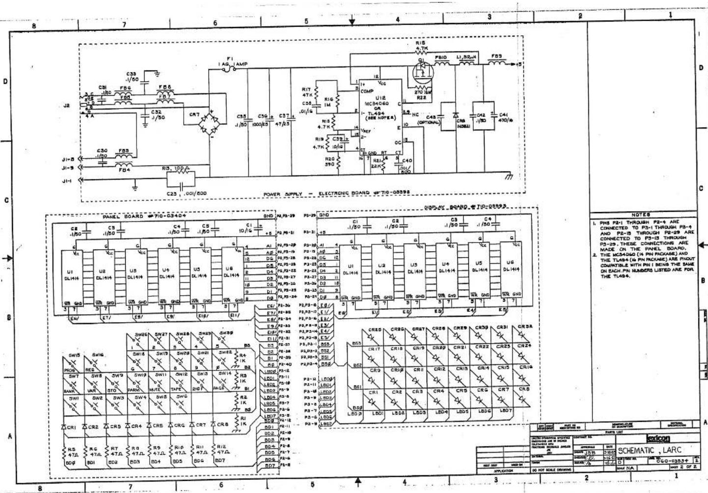


| LOT CODESCHIMATIC | PART IDDESCRIPTION NO. | SPECIAL SIZEDESCRIPTION | MATERIALDESCRIPTION | ||
| PARTS LIST | |||||
| SPECIAL DRAWING PROCESSEDINFORMATION ARE IN PROCESERATELLATION OF THETRACTURE MATERIALS ANDIN PART | SPECIAL NO. | SPECIAL | |||
| APPROVAL | DATE | ||||
| TUBE | SHEET | SCHEMATIC , LARC | |||
| ORDER NAME | ORDER NO | TITLE | DRAWN BY: | CHECKED BY: | |
| ITEMS | DRAWN BY: | DRAWN BY: | |||
| ITEMS | DRAWN NO.: | DRAWN NO.: | |||

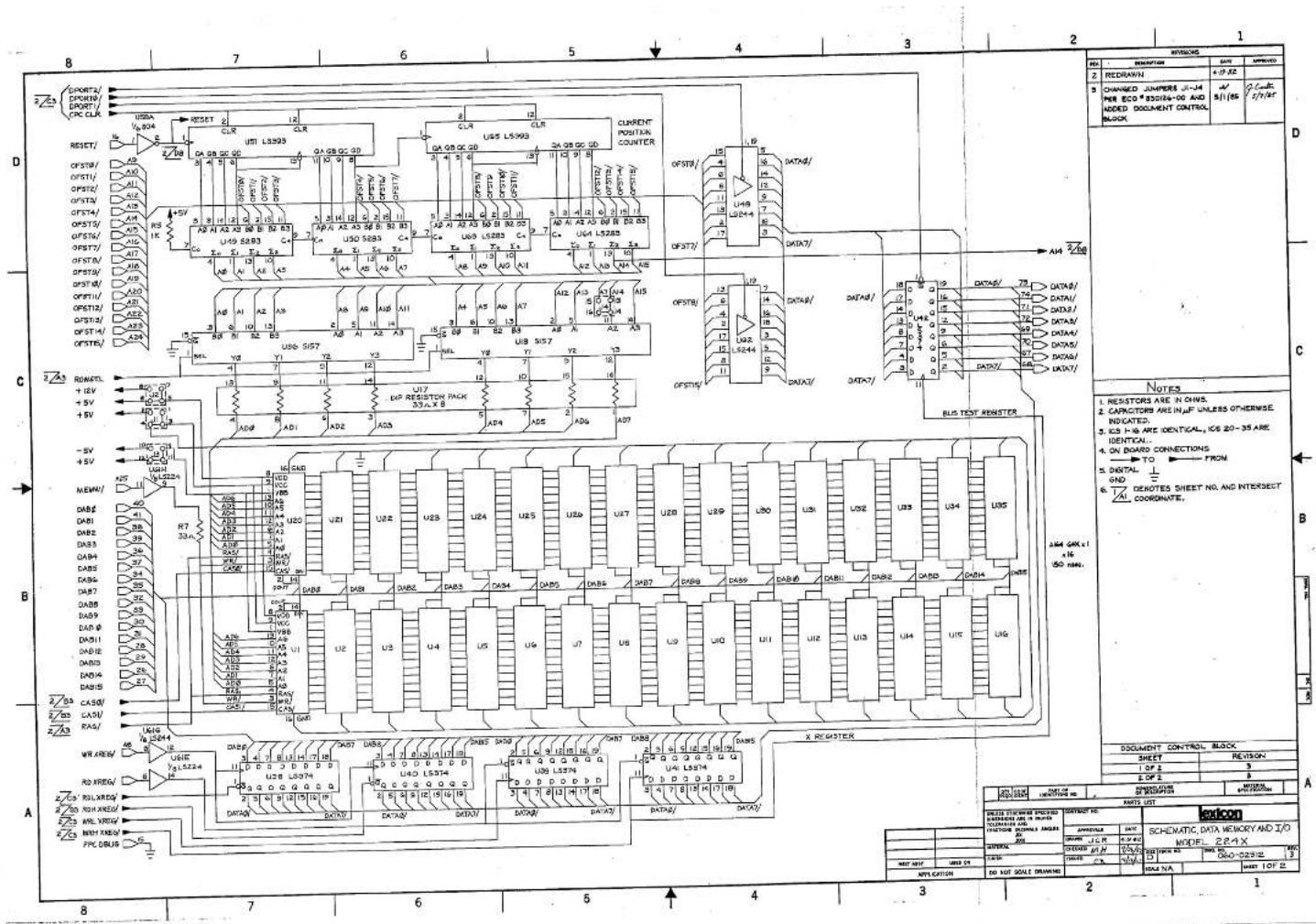


flowchart
graph TD
    A["OFFSET/"] --> B["16"]
    B --> C["A 16-Bit Adder"]
    C --> D["Address Multiplexer"]
    D --> E["Address Control"]
    E --> F["54k x 16 Data Memory Data"]
    F --> G["Diagnostic Ports"]
    G --> H["Output Port Code"]
    H --> I["Single Cycle/Continuous Run"]
    H --> J["Output Port Strobes"]
    G --> K["Input Port Strobes"]
    L["Control Signal Gen."] --> M["16"]
    M --> N["Transfer Register"]
    N --> O["8"]
    O --> P["8080 Data Bus"]
    Q["DHEM Control"] --> M
    R["8080 Address Bus"] --> S["8080 Control Bus"]
    T["8080 Data Bus"] --> U["8080 Address Bus"]
    V["8080 Data Bus"] --> W["8080 Control Bus"]
    X["8080 Data Bus"] --> Y["8080 Address Bus"]
    Z["8080 Data Bus"] --> AA["8080 Control Bus"]
    AB["16"] --> AC["16"]
    AC --> AD["16"]
    AD --> AE["16"]
    AE --> AF["16"]
    AF --> AG["16"]
    AG --> AH["16"]
    AH --> AI["16"]
    AI --> AJ["16"]
    AJ --> AK["16"]
    AK --> AL["16"]
    AL --> AM["16"]
    AM --> AN["16"]
    AN --> AO["16"]
    AO --> AP["16"]
    AP --> AQ["16"]
    AQ --> AR["16"]
    AR --> AS["16"]
    AS --> AT["16"]


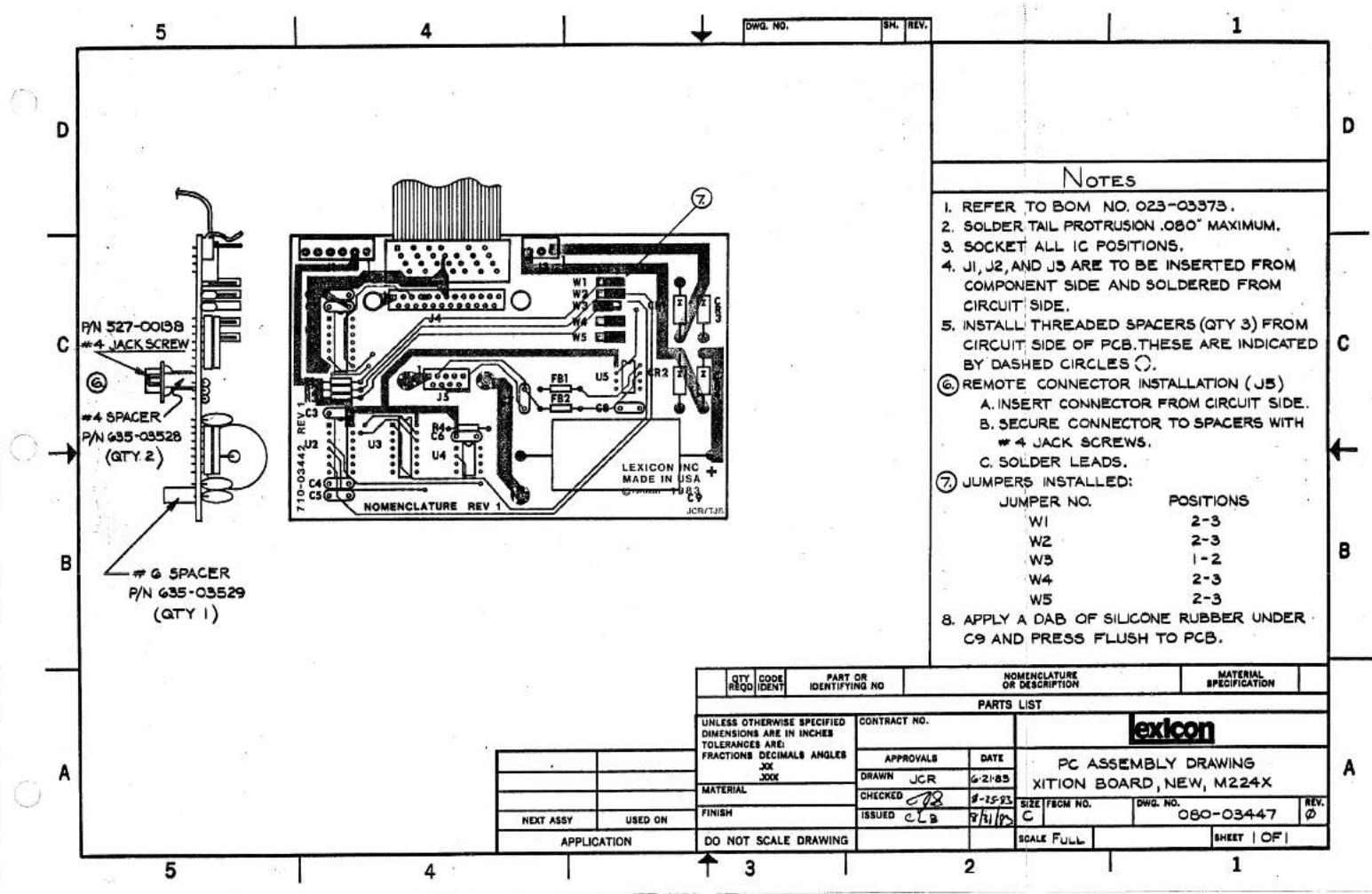


- Unpacking and Inspection
- Table of Contents
- Precautions....ii
- Unpacking and Inspection....ii
- Introduction 1.1
- Installation 2.1
- Operation 3.1
- Programs 4.1
- Notice
- Introduction
- 1.1
- Description
- 1.2
- Organization of This Manual
- Installation
- 2.1
- Power Requirements
- Interfacing
- Mounting
- Connections
- Patching
- Level Adjustments
- LARC front view
- Main display
- Headroom indicator (ppm response)
- Program-select and register-select keys
- Numeric-select keypad (1 to 0)
- Main operating keys
- Slider display line
- Parameter-control sliders
- PARAM accesses Parameter toggles
- Slider display-select keys
- Operation
- Introduction—The Basic Concept
- Banks, Programs, Pages, and Variations
- How To Load Programs
- How To Modify Programs
- How To Store and Recall Modified Programs
- STORE BX RY
- CONCERT HALL
- B3 R5 [B1 P1]
- How To Label Banks and Registers
- Tape Storage and Recall
- Note: Check all connections before storing data.
- STORE BANKS
- ON TAPE
- TAPE STORE
- COMPLETED
- VERIFY BANKS
- AGAINST TAPE
- VERIFY GOOD
- 000SE 000HE
- VERIFY BAD
- How The Controls Affect The Sound
- Variable Reverberation Parameters
- Decay Time vs. Frequency: LF and Mid Decay, Treble Decay, and Crossover.
- Parameter Toggles
- DYN DECAY [1]
- Pages 4.4 and 4.5
- Page 4.33
- Programs
- Halls—Bank 1
- Concert Hall—Program 1
- Bright Hall—Program 2
- Dark Hall—Program 3
- Rooms—Bank 2
- Room and Small Room—Programs 1 and 2
- Chamber, Rich Chamber, and Dark Chamber Programs 3, 4, and 5
- Inverse Room — Program 6
- Plates—Bank 3
- Plate and Small Plate—Programs 1 and 2
- Constant-Density (CD) Plates A and B—Programs 3 and 4
- Rich Plate — Program 5
- Effects—Bank 4
- Chorus & Echo—Program 1
- Resonant Chords—Program 2
- Multiband Delay—Program 3
- Splits—Bank 5
- Hall/Hall—Program 1
- Plate/Plate—Program 2
- Plate/Hall—Program 3
- Plate/Chorus—Program 4
- Rich Split—Program 5
- Program Block Diagrams
- Applications
- Reverberation Programs
- Re-creating Room Acoustics
- Creating Space or Ambience
- Thickening or Enriching Single Tracks
- Adding Loudness Without Increasing Peak Level
- Examples of General Applications
- Using the Reverbation Programs with Specific Sources
- Drums
- 1
- 2
- 3
- 4
- Vocals
- Dialog
- Orchestra
- 5.2
- Effects Programs
- Enrichment or Thickening
- Doubling, Chorusing, and Flanging
- Repeats
- Sound Modification
- Service
- 6.1
- Periodic Maintenance
- 6.2
- Software Updates
- 6.3
- Hardware Overview
- Lexicon Alphanumeric Remote Console (LARC)
- Transition Module
- Single-Board Computer (SBC) Module
- Nonvolatile Storage (NVS) Module
- Timing and Control (T&C), Data Memory (DMEM), and Arithmetic Unit (ARU) Modules
- Audio Input (AIN), Audio Output (AOUT), and Floating Point Converter (FPC) Modules
- Audio Transformer Module
- Power Supplies
- Troubleshooting
- Mainframe or LARC Does Not Power Up
- Unit Gives Improper Display or Error Message
- Unit Does Not Pass Audio or Distorts Audio
- Unit Cannot Recall User-Modified Programs
- Diagnostic Programs
- 6.6
- Module Exchange Program
- 6.7
- Returning Units for Service
- 6.8
- Ordering Parts
- Lexicon, Inc.
- Specifications
- Warranty
- Limited Warranty
- Register Log
- Variation Presets
- Rooms
- Plates
- Effects
- Splits
- Arithmetic Unit (ARU) Module
- Data Memory (DMEM) Module
- FPC -- Version 8.2.1
- Schematics and Assembly Drawings
- Troubleshooting Notes
- Miscellaneous notes
- Diagnostics
- Tape Interface Logic
- Buffered Bus and Sink logic
- UART Logic
- RS-422 Logic
- Litronix Display Logic
- ADC Logic
- Reset Logic
- Address Decoding Logic
- CPU
- LARC Theory of Operation
- Power Supply
- Register Log
- G SPACER
Brand : LEXICON
Model : M224XL
Category : Effects machine