
M200 - Effects machine LEXICON - Free user manual and instructions
Find the device manual for free M200 LEXICON in PDF.


| Type | Digital Reverberator / Effects Processor |
| Dimensions | 19 x 5.25 x 15 inches (483 x 133 x 381 mm) |
| Weight | 18 lbs (8.1 kg) net; 22 lbs (10 kg) shipping |
| Power Requirements | 100/120/220/240 VAC, 50-60 Hz, 75W (switch-selectable internal) |
| Programs | 6 basic programs: Halls, Plates, Chambers, Rich Plates, Rich Split, Inverse Room; each with up to 10 factory variations |
| Reverb Time Range | Approximately 0.6 to 70 seconds (program-dependent) |
| Predelay Range | 0 to 999 ms (program-dependent) |
| Size Control | Adjusts virtual room size from 1 to 99 meters |
| Frequency Response | Reverb signal: 20 Hz - 10 kHz ±1 dB; Direct signal: 20 Hz - 20 kHz ±0.5 dB |
| Dynamic Range | ≥84 dB typical (reverberant signal, 20 Hz - 20 kHz) |
| THD+N | ≤0.07% maximum at 1 kHz (reverberant signal) |
| Inputs | 2 balanced XLR, impedance >50kΩ, max input +24 dBm, gain switch 0/+20 dB |
| Outputs | 2 balanced XLR, transformer-isolated, impedance <150Ω, max output +24 dBm |
| Storage Registers | 10 non-volatile RAM registers for user-modified programs |
| Remote Control | Foot pedal jacks: Reverb Time (potentiometer), Program Step (momentary), Input Mute (latching) |
| Displays | 5-digit alphanumeric (program/register), 3-digit (predelay), 2-digit (reverb time/size), 12-segment LED level meter per channel |
| Cooling | Forced air with replaceable filter |
| Operating Temperature | 0°C to 35°C (32°F to 95°F) |
| Maintenance | Clean or replace air filter every 6 months; charge NiCad battery monthly if unit unused for extended periods |
| Mounting | Standard 19-inch rack mount, 5.25 inches high |
| Warranty | One year limited warranty (defects in material/workmanship) |
Frequently Asked Questions - M200 LEXICON
User questions about M200 LEXICON
0 question about this device. Answer the ones you know or ask your own.
Ask a new question about this device
Download the instructions for your Effects machine in PDF format for free! Find your manual M200 - LEXICON and take your electronic device back in hand. On this page are published all the documents necessary for the use of your device. M200 by LEXICON.
USER MANUAL M200 LEXICON
Lexicon Inc. reserves the right to make changes in this manual and the product it describes at any time and without notice.
© Copyright 1984 Lexicon Inc.
All Rights Reserved
No part of this manual may be reproduced or transmitted by any means or in any form, without prior consent in writing from Lexicon Inc.
Printed in the United States of America.
Lexicon Inc.
60 Turner Street
Waltham, MA 02154
(617) 891-6790
Telex 923 468
070-03567-2
12/84
Table of Contents
Precautions....v
Unpacking and Inspection....vi
1 Introduction 1.1
1.1 Description 1.1
1.2 Organization of This Manual 1.3
2 Installation 2.1
2.1 Controls, Indicators, and Connectors 2.2
2.2 Power Requirements 2.10
2.3 Installation and Interfacing 2.12
2.3.1 Mounting 2.12
2.3.2 Connectors 2.12
2.3.3 Connections for Studio Use 2.14
2.3.4 Connections for Live Performance ..... 2.14
2.3.5 Remote Control Functions 2.15
2.3.6 Level Adjustment 2.16
3 Operation 3.1
3.1 Summary of Basic Operations 3.1
3.1.1 Programs 3.1
3.1.2 Variations 3.2
3.1.3 Creating and Storing New Variations 3.2
3.2 Operating the 200—Step-by-Step Instructions ..... 3.3
3.2.1 Getting Started 3.3
3.2.2 Control Sequences 3.4
3.2.3 Calling Programs and Variations 3.4
3.3 Creating and Storing Modified Programs 3.8
3.3.1 Using the Storage Registers 3.8
3.3.2 Clearing a Register 3.11
Table of Contents
3.4 Controls and Features for Stage Performance ..... 3.11
4 Programs 4.1
4.1 The Basic Programs—Halls, Plates, Chambers 4.1
4.1.1 Halls—Program 1 4.2
4.1.2 Plates—Program 2....4.3
4.1.3 Chambers-Program 3 4.3
4.1.4 Rich Plates—Program 4 4.4
4.1.5 Rich Split—Program 5 4.5
4.1.6 Inverse Room—Program 6 4.5
4.1.7 The Infinite Reverb Control Feature 4.5
4.2 Variations 4.7
4.3 How the Controls Affect the Sound ..... 4.8
5 Service 5.1
5.1 Periodic Maintenance 5.1
5.2 Troubleshooting 5.1
5.2.1 Unit Does Not Power Up 5.1
5.2.2 Unit Does Not Pass Audio or Sounds Distorted ..... 5.2
5.2.3 Unit Gives Improper Display or Error Message ..... 5.2
5.2.4 Unit Cannot Recall User-Modified Programs ..... 5.3
5.2.5 Diagnostic Programs 5.3
5.3 Block Diagram 5.8
5.4 Returning Units for Service 5.9
5.5 Ordering Parts 5.10
6 Specifications/Warranty 6.1
6.1 Specifications.... 6.1
6.2 Limited Warranty 6.3
7 Register Log 7.1
Precautions
The 200 is a very well-behaved device; however, precautions consistent with good practice for any piece of audio gear must be observed as a matter of course. Always be sure to use the correct AC line voltage; before plugging in your 200, see Sec. 2.2 of this manual for power requirements.
Do not mount the 200 in a nonventilated rack—its maximum ambient operating temperature is 35^ C ( 95^ F).
Never attach power sources or audio power amplifier outputs directly to any of the 200's connectors. The 200's inputs are designed for line-level signals. If a power amplifier is used as a signal source, a suitable attenuator pad must be used to lower the level of the feed to the 200.
Before turning the 200 on or off, lower the volume on your power amplifier or monitoring system to avoid undesirable transients.
To prevent fire or shock, never operate the 200 in the rain or in exposed wet locations.
The 200 employs a NiCad battery pack to power 10 nonvolatile random access memory (RAM) registers, allowing users to store modifications to programs intact—even when the main power is off. If the unit is not used for three months, the battery pack could lose its charge, and the user-modified settings that were stored could be accidentally erased. Therefore, if the unit is not used for a long time, charge the battery pack monthly by turning on the power for a few hours.
The 200 requires only limited maintenance; see Sec. 5.1 of this manual.
Unpacking and Inspection
After unpacking the 200, save all packing materials for reshipment. Thoroughly inspect the 200 and packing materials for signs of damage. Report any damage to the carrier.
Introduction
1.1
Description
The Lexicon 200 Digital Reverberator is an economical, general-purpose digital reverberation device designed for recording studios, musicians, film/video production houses, and broadcasters. Its versatility and high quality are the result of Lexicon's extensive experience with digital audio. The 200 is carefully engineered to the same exacting standards that have earned Lexicon worldwide praise for its professional and broadcast digital audio products.
The 200 is a two-in, two-out all-electronic digital system; its advanced technology brings you:
Six different Reverb programs (expandable) — most with 10 factory preset variations — in full stereo

Size control — dramatically increasing the versatility of each program

Adjustable predelay and reverb time

Selectable pre-echoes, diffusion, reverb time contour, and rolloff

On-board mixing

Programmable nonvolatile memory for storing up to 10 user modifications with instant recall

Human-engineered panel controls for easy, intuitive operation

Remote control functions for stage performances

Input level switch to accommodate a wide range of instruments and input sources
Introduction
Balanced input and output connections with a maximum level of +24 dBm.
In the recording studio, the 200 performs all the functions of conventional reverb units, with the wide dynamic range and high sonic quality expected of Lexicon digital equipment. In addition, the 200's Hall and Chamber programs create realistic acoustic environments that, coupled with the size control, add emotional context to sound through associations with specific halls, chambers, or rooms.
Using the 200's remote control functions, stage performers can step through preset reverb effects, use an input mute to capture and sustain notes or chords, and control reverb time to change an effect during a performance. Vocalists and instrumentalists will find the 200 useful in stage-monitoring systems, and it can improve house systems on all instruments from vocals to drums.
As a sound reinforcement tool, the 200 can alter hall acoustics — increasing the apparent size and volume of a performance space and greatly expanding its versatility.
For film/video producers and broadcasters, the 200 can match studio-recorded dialog and effects to the ambience of a location recording and create reverb enhancements for special effects. It greatly adds to the impact of a given scene by placing the sound in an appropriate acoustic context; in addition, the 200 can increase the apparent loudness of dry recordings without increasing peak levels.
Every effort has gone into making the 200 perform to the highest industry standards.
1.2
Organization of This Manual
Section 2, Installation, shows the locations of controls, indicators, and connectors; discusses power and interfacing requirements; briefly describes common hookups; and shows how to adjust output levels.
Section 3, Operation, describes the basic operating instructions for the 200. It tells you how to (1) call up the reverberation programs and variations, (2) modify these effects using the front-panel controls, and (3) store modified effects in the 200's 10 memory registers.
Section 4, Programs, describes the reverberation programs and variations included in the current version of the 200's software. In addition, it gives an overview of how the controls affect the sound.
Section 5, Service, contains periodic maintenance instructions, general troubleshooting techniques, a block diagram, and instructions on how to return units for repair and order parts.
Section 6, Specifications/Warranty, lists the specifications for the 200 and includes the limited warranty.
Section 7, Register Log, provides a convenient log and area to document settings for user-modified programs.
Important: A product registration card for the 200 is included with its packing materials. Please fill out and return this card immediately, so we can supply you with important information on future software developments.
Installation
This section briefly describes the 200's controls, indicators, and connectors, and tells how to install the 200 in an equipment rack and connect it to other devices for studio or stage use.
System connections and the use of the controls on the 200 are slightly different for stage and studio uses, and instructions for using the 200 in live performance are discussed separately.
Installation
2.1
Controls, Indicators, and Connectors
Fig. 2.1. The 200 Front Panel.

1 POWER
This latching pushbutton turns the ac power on or off. Switching the power on also resets the unit.
2 RESET
The RESET button restarts the 200 and runs a series of diagnostic programs; if no errors are found, the 200 begins normal operation in the program mode with all switches and controls as they were set when the 200 was last used.
3 Numeric-select Keypad
When used in conjunction with the function keys, these keys
load reverberation programs (PGM), variations of programs (.), or the contents of memory registers (REG)
store user-modified programs in memory registers (STO)
clear memory registers (CLR).
Note: Changing programs or selecting registers or variations with different sizes causes a momentary fade-out and fade-in of the reverb. The F key is inactive.
4 Function Keys
When used in conjunction with the numeric-select keys, these keys
load reverberation programs (PGM), variations of programs (.), or the contents of memory registers (REG)
■ store user-modified programs in memory registers (STO)
clear memory registers (CLR).
5 Function Display Window
PROG indicates the number of the active program (or program and variation).
REG P indicates that the numeric-select keys are in program mode
Installation
REG r is displayed when REG is pressed and indicates that the numeric-select keys are in register mode; in register mode, the number of the register last called is displayed next to the r
C indicates that the clear register function is active
— is displayed when STO is pressed.
6 PREDELAY Control and Display
Adjusts and displays time in milliseconds before the onset of reverberation. After a program is loaded, the control must be moved through its displayed setting before it is activated.
7 PRE-ECHOES Button and Indicator
Toggles pre-echoes on and off (on when indicator is lit). The timing and levels of pre-echoes are set by the program variation and are independent of the predelay setting.
8 DIFFUSION Button and Indicators
This button steps through low, medium, and high values of diffusion. Diffusion is a measure of the extent to which the initial returns in reverberation are smoothed out in time.
9. REVERB TIME Control and Display
Adjusts and displays midrange reverb time in seconds for 60 dB of decay. After a program is loaded, the control must be moved through its displayed setting before it is activated.
10 SIZE Control and Display
Adjusts and displays the average dimension (in meters) of the virtual acoustic space created by the 200. After a program is loaded, the control must be moved through its displayed setting before it is activated. The size control affects the reverb time, and depending on the program, it can affect predelay. Note: Changing the SIZE control causes a momentary fade-out of the reverb as the new setting is implemented.
11 ROLLOFF Button and Indicator
This button changes the high-frequency rolloff (-3 dB) point:
HIGH = 10 kHz (48 dB/octave) MED = approximately 7 kHz (6 dB/octave) LOW = approximately 3 kHz (6 dB/octave).
12 RT CONTOUR Buttons and Indicators
The LOW button sets the reverb time for low-frequency (100-Hz) reverb to approximately one and a half (X1.5), equal to (X1), or one half (X.5) the indicated REVERB TIME. The HIGH button sets the reverb time for high-frequency (10-kHz) reverb to approximately equal to (X1), one half (X.5), or one quarter (X.25) the indicated REVERB TIME.
13 INPUT MIX Buttons
These buttons control the input mix: ■ both buttons out provides normal stereo reverb. ■ the left (or right) button in sends the left (or right) input through both reverb channels.
Installation
both buttons in sends the combined input channels to both reverb channels.
14 LEVEL Indicators
This 12-segment LED display shows peak/hold and OVERLOAD for each channel.
15 INPUT MUTE Button
When depressed, this momentary-contact button mutes both the dry signal in the mixer and the input audio signal to the reverberator to the 200. Reverberation output continues after the button is pressed.
16 REVERB STOP Button
When depressed, this button instantaneously halts the output of the 200's processing circuits, leaving only the dry sound.
17 INPUT LEVEL Control
This slider adjusts the input level of both channels simultaneously, affecting both wet and dry sound.
18 OUTPUT MIX Control
This slider adjusts the level of reverberation in the output from DRY (no reverberation) to WET (all reverberation). For studio use or with an external mixer, set this control to WET. For live performance, or in any situation where an exter-
nal mixer is not needed, the control can be used to adjust the mixture of reverberation and direct sound.
19 OUTPUT LEVEL Adjustment Screws
These two screws adjust output levels (maximum level is +24 dBm) for Left and Right outputs.
Installation
Fig. 2.2. The 200 Rear Panel.

1 GAIN Switch
This pushbutton switches the input gain from 0 to +20 dB. Start with the button out; if there is insufficient gain at the maximum setting of the front-panel INPUT LEVEL slider (see Fig. 2.1), lower the slider, push in the button, and raise the slider again. In the +20 dB position, the 200 can be used with low-level sources, such as guitar pickups.
2 INPUTS
LEFT and RIGHT inputs accept balanced 3-pin male XLR connectors. Input impedance is >50 kilohms. The rear-panel GAIN switch allows the 200 to accommodate input levels from -18 to +24 dBm.
3 OUTPUTS
LEFT and RIGHT outputs are balanced and transformer-coupled, accepting 3-pin female
XLR connectors. Output impedance is <150 ohms, and maximum output level is +24 dBm.
4 REVERB TIME Control Jack
This jack accepts a standard 1/4-in. phone plug (tip/ring/sleeve) wired to a control pedal equipped with a 50-kilohm potentiometer between the tip, ring, and sleeve (optional foot pedal: Lexicon A-CP-41); it remotely controls reverb time between the minimum value obtainable in the reverberation program and the value set on the front-panel REVERB TIME control.
5 PROGRAM STEP Control Jack
This jack accepts a standard 1/4-in. phone plug (tip/sleeve) wired to a footswitch with a momentary contact between the tip and sleeve (optional footswitch: Lexicon A-FS-41 — right pedal); it steps the 200 through the storage registers, programs, or variations in ascending order. An empty register causes a jump back to the first register in the sequence.
6 INPUT MUTE
This jack accepts a standard 1/4-in. phone plug (tip/sleeve) wired to a footswitch so that shorting between tip and sleeve effects a software-driven input mute that (unlike the front-panel INPUT MUTE switch) interrupts only the input to the reverb processor (optional footswitch: Lexicon A-FS-41 — left pedal). Reverb decays normally and the dry sound continues; this jack can be used to bypass the 200. While the mute is in effect, OFF appears on the front-panel PREDELAY display. New programs or registers can be called while this mute is in effect.
Installation
7 REMOTE 1 and REMOTE 2
These cutouts are provided to accommodate future options.
8 FUSE
Mains fuse holder. Replace with 3AG 1A slow blow for 100/120-Vac operation, 3AG 0.5A slow blow for 220/240-Vac operation (see Sec. 2.2).
9 Power Cord Connector
Accepts standard 3-pin IEC (NEMA) power cord (included).
2.2
Power Requirements
The factory preset nominal operating voltage appears on the rear panel; maximum power consumption is 75 W. The power cord (included) uses a standard 3-pin IEC connector, providing chassis grounding to the ac mains line. Note: The 200 can be operated at 100, 120, 220, or 240 Vac (-10%, +5%) at 50 to 60 Hz, depending on the positions of two voltage changeover switches inside the unit (in the left rear) and the rating of the mains fuse on the rear panel.
Voltage Changeover. Voltage changeover must be performed by a qualified service technician. To change the voltage, have a technician carry out the following procedure:
1
Remove the power cord.
2
Remove screws holding the top cover in place.
3
Using a small screwdriver, set the two voltage changeover switches to the appropriate settings shown in Fig. 2.3. (Move screwdriver in direction of arrows.)
4
Reinstall the top cover.
5
Make sure the proper rear mains fuse is installed in the rear panel (see Table 2.1); install a new fuse if necessary.
6
Affix a label on the rear panel indicating the new voltage requirements and refit the power cord.
Fig. 2.3. Voltage Changeover Switch Settings for Operating Voltages.


bar
120V Nominal | Voltage Level | 120/240 (Left) | 220/240 (Right) | | :--- | :--- | :--- | | (108-126V) | ↑ | ↓ |

bar
240V Nominal | Voltage Range | Top Section (Black) | Bottom Section (White) | | :--- | :--- | :--- | | 120/240 | ↑ | ↑ | | 220/240 | ↑ | ↑ | | 100/120 (216-252V) | ↑ | ↑ | | 100/120 | ↑ | ↑ |Installation
Table 2.1. Proper Rear Mains Fuses for Operating Voltages.
| Nominal Voltage (Vac) | Operating Range (Vac) | Fuse |
| 100 | 90-105 | 3AG 3A slow blow |
| 120 | 108-126 | 3AG 3A slow blow |
| 220* | 198-231 | 3AG 1.5A slow blow |
| 240* | 216-252 | 3AG 1.5A slow blow |
*Units factory-preset for 220 or 240 Vac are shipped with 20-mm fuse adapters; for these units, equivalent 20-mm fuses can be used.
2.3 Installation and Interfacing
2.3.1 Mounting
The 200 mainframe can rest on any flat surface or it can be mounted in a standard 19-in. relay rack; it is 5 1/4 in. high and 15 in. deep. Do not mount the 200 in a nonventilated rack. Do not obstruct ventilation space around the cooling fan (on the left side panel), the ventilation slots (on the left and right side panels), or the heat sink fins (on the rear panel); also, do not install the 200 above heat-producing equipment. Its maximum ambient operating temperature is 35°C (95°F).
To protect from mechanical shock during transport, support the rear chassis of rack-mounted units.
2.3.2 Connectors
Input and Output Connections. The rear-panel inputs and outputs use XLR connectors. The two inputs, LEFT and RIGHT, mate with 3-pin male XLR connectors. The corresponding two outputs mate with 3-pin female XLR connectors. Figure 2.4 shows the wiring diagrams
for these connectors. The inputs are balanced with pin 2 = high; impedance is 100 kilohms in parallel with 150 pF for balanced inputs and 50 kilohms in parallel with 300 pF for unbalanced inputs. The rear-panel GAIN switch allows the 200 to accommodate input levels from -18 to +24 dBm. The outputs are balanced and transformer-coupled with pin 2 = high. Output impedance is <150 ohms, and maximum output level is +24 dBm.
Fig. 2.4. Wiring Diagram of XLR Connectors.
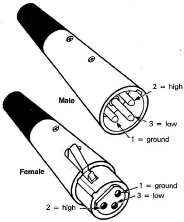
For single-ended (unbalanced, two-conductor) connections, connect pins 1 and 3 to ground.
Installation
Because the 200's inputs are balanced, the pin-2-low convention can be used, provided it is used consistently for both inputs and outputs.
Warning: Reversing polarity on either input or output connectors may produce audible phase-inversion effects. Make sure the inputs and outputs to all channels are wired consistently. Input polarity can be easily checked by pushing in both front-panel INPUT MIX buttons while feeding identical signals to the two channels; with the input channels combined, there is practically no output if the input phases are different.
2.3.3 Connections for Studio Use
In the studio, the 200 can be used in a separate echo loop, and its outputs combined with the source as echo returns. Connect it as shown in Fig. 2.5, and set the front-panel OUTPUT MIX slider all the way up to WET. The 200's outputs can also go directly to the tape or monitor; the proportion of reverberant sound would then be adjusted with the OUTPUT MIX slider.
The LEFT and RIGHT inputs to the 200 can be used independently for a stereo source. With a monaural source, use either input and push the corresponding INPUT MIX button to send the signal to both processor inputs.
2.3.4 Connections for Live Performance
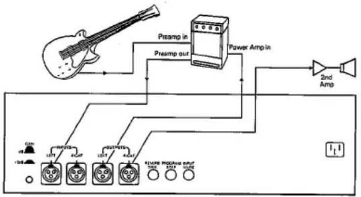
Because it contains its own input and output mixing facilities, the 200 can be connected in series with other line-level devices. The amount of reverb is then controlled with the OUTPUT MIX slider.
Fig. 2.5. Connecting the 200 for Studio Use.

flowchart
graph TD
    A["Source I"] --> B["Device"]
    C["Source N"] --> B
    B --> D["Main & Monitor Outputs"]
    D --> E["Amp"]
    B --> F["Effects Sends"]
    F --> G["Amp"]
    H["CAH 43"] --> I["LEFT"]
    H --> J["RIGHT"]
    H --> K["LEFT"]
    H --> L["RIGHT"]
    I --> M["Ground"]
    J --> M
    K --> M
    L --> M
    M --> N["Output"]
    style A fill:#f9f,stroke:#333
    style C fill:#f9f,stroke:#333
    style H fill:#ccf,stroke:#333
Fig. 2.6. Connecting the 200 for Live Performance.
flowchart
graph TD
    A["Preamp in"] --> B["Presamp out"]
    B --> C["Power Amp in"]
    C --> D["2nd Amp"]
    E["Input"] --> F["OUTPUTS"]
    F --> G["OUTRIS"]
    G --> H["OUTPUT"]
    H --> I["OUTPUT"]
    I --> J["OUTPUT"]
    J --> K["OUTPUT"]
    K --> L["OUTPUT"]
    L --> M["OUTPUT"]
    M --> N["OUTPUT"]
    N --> O["OUTPUT"]
    O --> P["OUTPUT"]
    P --> Q["OUTPUT"]
    Q --> R["OUTPUT"]
    R --> S["OUTPUT"]
    S --> T["OUTPUT"]
    T --> U["OUTPUT"]
    U --> V["OUTPUT"]
    V --> W["OUTPUT"]
    W --> X["OUTPUT"]
    X --> Y["OUTPUT"]
Monaural sources can be connected to either input; pressing the corresponding INPUT MIX button sends the signal to both channels of the 200, which will still provide stereo reverberation. Figure 2.6 shows a typical setup for a live performance.
2.3.5 Remote Control Functions
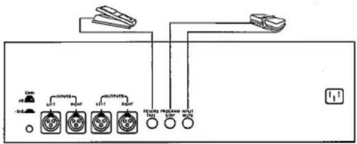
Three rear-panel phone jacks permit the connection of foot pedals to control reverberation time, mute the input of the 200's reverb processor, and step through one or more prearranged series of effects. Connect a Lexicon A-FS-41 dual
Installation
footswitch assembly (optional) to the INPUT MUTE and PROGRAM STEP jacks as shown in Fig. 2.7. These two jacks accept standard 1/4-in. tip/sleeve phone plugs and can be connected to pedals with latching and momentary contacts, respectively. The REVERB TIME jack accepts a standard 1/4-in. tip/ring/sleeve phone plug and can be connected to either a potentiometer (>50 kilohms), such as the optional Lexicon A-CP-41 foot pedal, or to an external voltage source with a range of 0 to +5 Vdc. If a potentiometer is used, wire high to ring, low to sleeve, and wiper to tip; if a voltage is used, apply it to the tip. Note: Although this input is protected, voltages greater than +5 Vdc may cause the 200 to behave unpredictably.
Fig. 2.7. Foot Pedal Connections.
2.3.6 Level Adjustment
The output level is factory preset at +12 dBm into a 600-ohm load with the front-panel OUTPUT MIX control set to DRY and a peak amplitude falling just short of illuminating the +12 dB/OVERLOAD indicator on the level display.
To adjust the output level, set the OUTPUT MIX control on the right side of the panel all the way down to DRY.
Start with the rear-panel GAIN button in the 0-dB (out) position. Feed a musical source (or 1-kHz test tone) at the maximum peak level that you use in your system into each input (RIGHT and LEFT) of the 200. Next, bring up the INPUT LEVEL slider until the peak input amplitude falls just short of illuminating the +12 dB/OVERLOAD indicator on the level display.
Important: The headroom indicator is an instantaneous peak-reading meter and shows the true maximum level of the input signal. Therefore, optimum operation occurs when input levels light the amber LEDs in the headroom indicator.
If the signal level is too low (that is, if the maximum input signal never reaches +6 dBm), bring the INPUT LEVEL slider down, press in the rear-panel GAIN button to the +20 dB position, and try again.
When the input gain setting is satisfactory, adjust the OUT LEVEL screwdriver pots to match your associated equipment. For a level indication of 0 dB on the 200, the available output range is approximately -12 to +12 dBm.
Warning: Do not overdrive the 200 — its clipping characteristic, like that of other digital audio equipment, is very abrupt.
Operation
The 200 is a sophisticated and versatile reverberation device. Its system of programs and variations makes this versatility immediately available, even to inexperienced users. This section summarizes basic operating procedures and gives step-by-step instructions of how to call programs and their variations and create and store modifications to programs.
The 200 digitizes incoming signals and processes them with its internal computer; it then reconverts the processed signals to analog for output. Because the modifications to sound are under the control of the 200's high-speed processor, the range of modifications is extremely wide.
Because the 200 is software-driven, it can simulate the response of many different kinds of actual spaces and mimic other artificial reverberation devices. The 200 provides true stereo reverberation with 10 kHz bandwidth.
3.1
Summary of Basic Operations
3.1.1 Programs
A set of instructions is called a program. The 200 has six basic programs:
1
Halls, which duplicate the effects of rooms or concert halls
2
Plates, which simulate reverberation plates
3
Chambers, which duplicate the effects of reverberant chambers, from small to very large
4
Rich Plates, which simulate gold-foil reverberation plates
Operation
5
Rich Splits, which allows the left and right channels to be used independently
6
Inverse Room, which allows the envelope of the reverb tail to be continuously varied
More programs may be added in the future as part of Lexicon's continuing software update program.
A program is called by pushing PGM followed by one of the numbered buttons on the keypad (1 for Program 1, 2 for Program 2, etc.).
3.1.2
Each program has up to 10 variations, and each variation has its own distinct sound. The variations are written as decimal extensions of the program number; thus, Variation 5 of Program 1 is Program 1.5. (A complete list of these variations is given in Sec. 4.) When you select, or call, a new program, variation 1 of that program is automatically loaded into the 200. After a program has been called, other variations can be run by pushing the decimal point (.) on the keypad followed by the variation number.
3.1.3
The sound of any variation can be modified by using the three knobs — PREDELAY, REVERB TIME, and SIZE — and the buttons to the right of the knobs — PRE-ECHOES, DIFFUSION, RT CONTOUR, and ROLLOFF. By changing the operating parameters of any program, you are, in effect, creating your own variations.
Once you have modified the program parameters and achieved the precise sound you want for a given application, you can store it for future use by pushing STO and holding it down
while pushing the numeric-select key corresponding to the number of the register you wish to use. This procedure stores the basic program (along with all control settings) in the register.
The modified program that has been stored can be recalled later by pressing REG followed by the same numeric-select key.
The preceding instructions summarize the entire operation procedure for the 200. Section 3.2 is a tutorial that expands on the preceding information and describes how to change the reverberation parameters to create your own variations.
3.2
Operating the 200 — Step-by-Step Instructions
3.2.1
Install the 200 as directed in Sec. 2.3, which covers mounting, connection to other equipment, and level setting. Once the procedures in Sec. 2.3 have been carried out and the 200 is in your echo loop or instrument setup, begin by listening to the echo return alone; then add reverb to the direct sound.
Power up the 200 by pressing the POWER switch on the front panel. If the power is already on, hit the RESET button. The machine takes about 15 seconds to run its built-in diagnostic procedures and verify proper operation; during power-up, the PROG display cycles three times from 6.1 to 6.8, and the software version number appears in the PRE-DELAY display.
If the machine is operating normally, P appears in the REG display, and the reverberation program and settings that were in use when the 200 was last turned off will load and run. If the
Operation
diagnostics find an error in the operation of the machine, the PROG display gives an error message containing the letter E, such as E25. If an error message is displayed, refer to Sec. 5.2.5 (Troubleshooting — Diagnostic Programs) for assistance.
3.2.2 Control Sequences
Operating the 200 involves pushing buttons and turning knobs. The order in which these things are done is important, so we use a consistent notation to represent it. A comma separating button pushes indicates a sequence; a slash indicates simultaneous operation:
PGM, 1 means Push and release PGM Push and release 1
STO/3 means Push and hold STO Push 3 Release STO and 3
3.2.3 Calling Programs and Variations
Whenever the 200 is turned on or reset, the PROG display shows whatever program was last used. For now, refer to Fig. 3.1 and call Program 1:
■ Push PGM, 1
This is Program 1, Variation 1 (or Program 1.1). The PROG display reads:
1 P
with no decimal point or suffix; pushing another button would call one of the other programs.
Fig. 3.1. Calling Program 1.
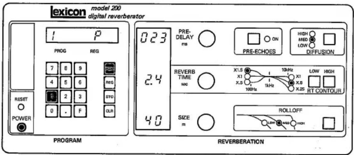
Program 1.1 mimics the reverberation of a large concert hall. As Fig. 3.1 shows:
PREDELAY = 23 milliseconds
REVERB TIME = 2.4 seconds
SIZE = 40 meters
A predelay of 23 milliseconds for a hall represents the time before the first reflection is heard; predelay is analogous to the depth of the stage behind the performer in an actual hall. A reverb time (also referred to as RT 60) of 2.4 seconds is moderate for a concert hall of 40 meters average dimension, as indicated on the SIZE display.
Note that this variation has no pre-echoes, which indicates that the hall has a large and not very reflective stage enclosure. Diffusion (defined in Sec. 4.3) is Medium. The RT CONTOUR display indicates that at 100 Hz the reverb time is 1.5 times the displayed value of
Operation
2.4, or 3.6 seconds; at 10 kHz the reverb time is 0.5 times 2.4, or 1.2 seconds. In addition, the ROLLOFF display shows that the hall has a rolloff of 6 dB/octave above 7 kHz (Medium) — a typical characteristic of large halls resulting from air absorption.
Now call another reverberation program.
Push 2
Fig. 3.2. Calling Program 2.
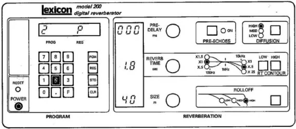
Because you are in the program-select mode, with P showing in the program display, pushing the numeric-select key 2 calls Program 2.1 (Variation 1 of Program 2). As Fig. 3.2 shows, like Program 1.1, this variation has large size, medium reverb time, and no pre-echoes. But the sound is very different, because this program is designed to be more like a plate-type reverb unit than a concert hall.
A plate has a much higher density of early reflections than a hall, and its sound is also much brighter and more colored. In general, programs with many early reflections, such as
plates, are better for percussive material; vocals, organ, flute, or other "smooth" sources are clearer and more natural-sounding with Program 1 (Hall).
To see how much variety is available within a single program, call Variation 9 of Program 2.
■ Push . , 9
Fig. 3.3. Calling a Variation.

As Fig. 3.3 shows, Program 2.9 has small size, short reverb time, and strong pre-echoes. The sound is much brighter, closer, and drier than either Programs 1.1 or 2.1.
For a more detailed discussion of the programs and their variations, see Sec. 4; Sec. 3.3 describes how to modify programs and variations and store the modifications for future use.
Operation
3.3
Creating and Storing Modified Programs
Although the programs and variations supplied with the 200 provide a great variety of sounds, they do not by any means exhaust its potential. By using the front-panel controls you can create totally new variations. These modified programs can then be stored in one of 10 memory registers in the 200, and recalled instantly. The 200's memory registers are nonvolatile, and their contents are retained even if the 200 is turned off and disconnected from ac power.
Caution: The 200 employs a NiCad battery pack to power its nonvolatile memory registers. If the unit is not used for three months, the battery pack could lose its charge, and user-modified settings that were stored in memory registers would be erased. If the unit is not used for a long time, charge the battery pack monthly by turning on the power for a few hours.
3.3.1 Using the Storage Registers
To illustrate the process of creating and storing new variations, let's change a single parameter of a program variation, then store and retrieve the modified program. (Section 4.3 gives detailed descriptions of how the controls modify the sound.)
Call Program 2.9 as shown in Sec. 3.2.3 (push PGM, 2, . , 9). Activate the REVERB TIME control by turning it (down or up) until the position of the knob passes through the current setting. Then turn the control up to 5.3 seconds. The new sound is dramatically changed from the original Program 2.9.
Now store the new sound in Register 1:

Push STO/1
Fig. 3.4. Storing a Modified Program in a Register.
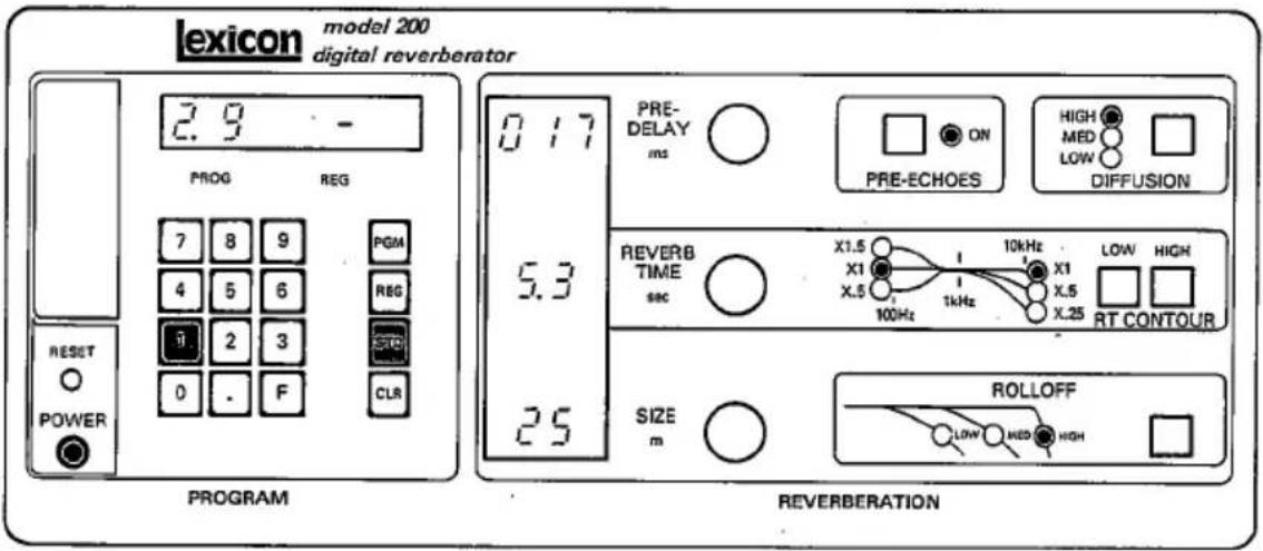
The two buttons must be pushed simultaneously (which helps prevent accidental erasure of register contents). As Fig. 3.4 shows, as soon as STO is pushed, a dash appears in the REG display. While STO and 1 are both down, the number of the register being filled appears in the REG display.
When you have a sound that you like, it is wise to store the modified settings in a register right away. Pushing other keys at this point could cause one of the basic programs to be read into memory, and your settings may be lost.
If you wish to compare the variation you have just created with the original, call up the original (after storing yours!) and store it in a register adjacent to the one you just filled. This procedure permits quick comparison between any two or more versions of the same basic sound.
Operation
To recall the contents of a register, just push REG followed by the appropriate number. To illustrate how this works, first call Program 1 by pushing PGM, 1. Now go back to the variation you created a moment ago:
Push REG, 1
Fig. 3.5. Calling the Contents of a Register.

The REG display shows:
r1
indicating that the combination of settings stored in Register 1 has now been recalled. The PROG display shows 2, which indicates that Register 1 contains a modification derived from Program 2.
From this control mode, you can call the contents of any register by simply pushing the corresponding numeric-select key, just as you can call different programs when the P is lit in the REG display. Attempts to call an empty register are ignored.
3.3.2 Clearing a Register
Any register can be cleared by pushing CLR and, while holding it down, pushing the register number, similar to storing settings. For instance, to clear Register 1,
push CLR/1
This capability is especially important if you want to use the 200 for live performance.
3.4
Controls and Features for Stage Performance
The 200 is compact and simple to operate, making it easy to use its effects in live performance. For the proper connections between the 200 and other equipment and specifications for the associated foot-pedal controls, see Sec. 2.3.5.
The REVERB TIME pedal adjusts that parameter from the minimum available for a particular program to the value set on the front-panel REVERB TIME control.
The INPUT MUTE pedal should be equipped with a latching pair of contacts. When pressed, it interrupts the input to the 200's reverb processor while leaving the dry sound unaffected. Reverberation decays normally following activation of this control. (This is in contrast to the front-panel INPUT MUTE button, which also interrupts the dry sound, and the front-panel REVERB STOP button, which halts reverberation instantly.) When the rear-panel INPUT MUTE is in effect, OFF appears in the 200's PREDELAY display.
Operation
The PROGRAM STEP pedal can be used during a performance to step through one or more series of prearranged reverb sounds stored in registers. The sounds must be stored in consecutive registers, separated by a cleared register (a register with no contents).
To see how the PROGRAM STEP function works, first fill a series of consecutive registers, followed by a cleared register. When reading the left column, remember that a comma separates the buttons in a sequence of operations, and a slash indicates simultaneous operation.
| ButtonPushes | Effect |
| PGM, 1 | Calls Program 1.1 |
| STO/0 | Stores Program 1.1 in Register 0 |
| ., 5 | Calls Program 1.5 |
| STO/1 | Stores Program 1.5 in Register 1 |
| PGM, 2, . , 9 | Calls Program 2.9 |
| STO/2 | Stores Program 2.9 in Register 2 |
| CLR/3 | Clears Register 3 |
Now the first three registers are filled and the fourth is empty. Call the first register by pushing REG, 0. Pushing the PROGRAM STEP pedal three times cycles through registers 1 and 2, then returns to 0.
If you now fill registers 4, 5, and 6 as previously described, and then push REG, 4, the pedal cycles through these three registers. In this way, you can prepare two or three groups of registers in advance, and use each group separately during the course of a set.
The PROGRAM STEP pedal is also active in other modes: in program mode, it cycles through the programs; if a variation is selected, it cycles through all the variations of whatever program is running.
Programs
The 200 can produce a large variety of different sounds. The programs described in this section are the framework upon which this variety is built. In many situations, one of the standard variations may be exactly what you are looking for. Where more creative control is required, you can create and store your own unique sounds. The following descriptions assume that you have read Section 3 of this manual and are familiar with the controls of the 200.
Because the 200 is a stereo device, it produces much wider and fuller reverberation than do monaural devices. It is not necessary or desirable to pan the reverb to the same location as the source; the reverberant space has an image of its own.
4.1
The Basic Programs
Your Model 200 Version 1.3 software has six programs:
1
Halls
2
Plates
3
Chambers
4
Rich Plates
5
Rich Split
6
Inverse Room
Programs
Each of these programs has a number of variations. More programs may be added in the future as part of Lexicon's continuing software update program.
4.1.1 Halls — Program 1
The Hall program and its variations mimic a variety of acoustic spaces. When set for large sizes, these programs put their sound behind the music instead of with it, lending a sense of space and depth, and adding ambience while leaving the music unchanged. The Halls have relatively few early returns that build in number as time progresses. This characteristic accounts for the very clean, distinct initial sound of this program.
The SIZE control makes a tremendous difference to the sonic impact of the Hall program. Acoustic impressions of size play an important part in the emotional effect of music or speech. Very small sizes — 5 meters or so — suggest a closet, giving a confined, stifling sound. A size of about 10 meters gives a living-room sound, 20 meters a large room, 30 meters a recital hall, and 40 meters a large concert hall. Each of these spaces lends its own emotional feel to the sound.
The Halls are useful for a wide variety of tasks. The large sizes are especially good with classical music. For popular music, the Halls can be used on the final mix to put the separately recorded tracks in a real-sounding acoustic space, giving the sense that they all belong to the same performance.
Most of the standard variations of this program have moderate to low diffusion, which
makes them sound clearer and more natural for vocals. High diffusion, as used in Variation 4, works better with percussion. The level and timing of the pre-echoes are different in the individual variations.
4.1.2 Plates - Program 2
The Plate program and its variations have very dense early returns, high initial diffusion, and a bright, colored sound. The Plates are designed to be heard as part of the music, mellowing and thickening the initial sound itself. This sound is usually associated with the word reverb, and is useful for all popular music.
Plate-type reverb has traditionally been the first choice for percussion. With adjustable parameters, the same basic algorithm is useful for many other tasks as well. Smaller size plates tend to sound denser, smoother, and more colored than larger ones.
The difference between the Hall and Plate programs is fundamental and can always be heard no matter what the settings of the reverberation parameters are. In particular, the Plate program always colors the sound by emphasizing the high frequency spectrum. The degree to which this is noticeable depends primarily on how much reverb is used in the mix, but it also varies with the use of other settings on the 200.
4.1.3 Chambers - Program 3
The Chamber program combines features of the Halls and Plates with a few benefits of its own. The coloration is notably low, making the program useful in both classical and
Programs
popular music. The decay gives little or no sense of a specific space, but with predelay and pre-echoes the sound can be quite spacious. (Variations 2 and 5 are examples of this, and sound very good on classical music.)
The sound of this program is strongly dependent on the setting of the SIZE control. At settings of 30 meters or below, the program has a dense, tight sound — useful for percussion or vocals. At higher settings, the sound is smoother and density becomes noticeably lower than in either of the other programs; these settings are useful with music that has already been mixed. The SIZE control can be set as high as 99 meters, giving a space approximately the size of the Astrodome. Diffusion should be set high for best results with larger sizes. Diffusion scales with size, resulting in a natural tightness in the small size rooms and greater smoothness in the large sizes.
4.1.4
The Rich Plates program sounds similar to Program 2 and can be used on the same material. However, it produces a less metallic decay (similar to a gold-foil plate) and is smoother. The difference is particularly audible on kick drums. The build-up of sound in the Rich Plates program is slightly more gradual and less explosive than in Program 2.
Pre-echoes are non-diffused. In both the Rich Plates and Rich Chambers programs (and unlike the other programs in the Model 200) the ROLLOFF button affects the sound after the reverb instead of before. By setting the ROLLOFF to LOW, the noise floor of the 200 is lowered.
4.1.5
The Rich Split program allows the two input channels of the 200 to be processed independently, so different reverberation sounds can be applied to different tracks in a mix. When stereo reverb is not required, this allows the 200 to do the work of two mono reverb units.
The sound of the Rich Split program is similar to the Chambers program (program 3). When the Rich Split program is loaded, the reverb time, contours and predelay for the left channel are displayed, and "L" appears in the main display. Press the F button and the right channel settings are displayed, and "r" appears in the main display. Except for PRE-ECHOES, SIZE, ROLLOFF, and DIFFUSION, the controls can be used to adjust each channel independently. The settings may be stored in registers.
4.1.6
The Inverse Room program allows the envelope of the reverb tail to be continuously varied. The effect is similar to a gate, but it does not depend at all on the level or the complexity of the signal. It produces a reverb that sounds like a room for a fraction of a second, and then drops off abruptly.
The Slope control is the reverb time control, with a slope of 50 being relatively flat. A slope of about 80 produces an inverted effect, while slopes of 30 or so sound more natural.
4.1.7
Programs 3, 4, and 5 include an effect called Infinite Reverb. Infinite Reverb lets you capture a sound forever in the 200's memory. A very
Programs
short "sonic snapshot" is taken, and is repeated continuously, with no splicing glitches or other unpleasant artifacts audible. At large size settings, the sound takes on a lush texture, and successive layers of sound can be added to produce spectacular chords with infinite sustain. At smaller size settings the sound is less spacious, with a slight tremelo.
To begin experimenting with this effect, use a very large size (over 70), set the treble decay to X1, diffusion high, and pre-echoes off. To activate the Infinite Reverb, turn the REVERB TIME control all the way up. The sound will continue without degradation until power is interrupted, or any change is made to the 200's controls. To capture another note along with the first, turn down the REVERB TIME control slightly, and then immediately turn it all the way up again. With practice, you should be able to layer several notes.
You may wish to use a Lexicon A-CP-41 foot-pedal attached to the rear panel REVERB TIME jack. This permits a musician to control the Infinite Reverb effect while performing.
Another way to layer involves the 200's registers. Set one register for Infinite Reverb, and another for slightly less reverb time. Switch between the two registers to create layers. You can switch with either the front panel controls, or a footswitch attached to the rear panel PROGRAM STEP jack.
Note: In Program 5, Infinite Reverb is only available in the left channel. Modifying the right channel reverb time while the left channel is repeating is not recommended.
The ROLLOFF control affects the sound while it is repeating, but the changes are reversible. The RT CONTOUR buttons can be changed for a short period of time to modify the repeating sound, but must be restored to X1 or X1.5 to keep the sound from decaying away.
4.2
Variations
Each of the six programs in the 200 has up to 10 variations. These variations are organized similarly in all programs.
Figure 4.1 shows the general organization of variations by parameters for each program. The size of the reverberant space is the same within each row; reverb times and pre-echoes are the same in each column.
Fig. 4.1. Organization of Variations within Each Program.
Reverb Time medium medium short
Pre-echoes none |medium high

other
| Size | small | medium | Large | Large | |---|---|---|---|---| | 7 | 7 | 4 | 1 | 0* | | 8 | 8 | 5 | 2 | • | | 9 | 9 | 6 | 3 | F |*Variation 0 is the same as Variation 1, except it is more metallic and should be used if modulation noise occurs with pure high-frequency tones or if clicking occurs with pure low frequency tones.
Programs
The variations have been arranged to make them easy to remember and use. The first column has no pre-echoes and may be the most generally useful. Variation 1 should always be tried first when ambience or depth is needed (this variation is automatically running when a program is first loaded). It tends to be best on mixed material.
When you need a brighter and tighter reverb, especially on percussive material, try Variation 4.
Variation 7 is best when an impression of very small size is required.
Variations 2, 5, and 8 add pre-echoes that imitate floor and stage reflections. They tend to strengthen a close-miked sound, making it louder and fuller.
Variations 3, 6, and 9 add loud pre-echoes to simulate strong reflections from hard surfaces. With their short reverb times, these variations sound like a gym or a modern general-purpose auditorium.
Variation 0 is the same as Variation 1, except that it is noticeably more metallic on all material. It should be used if modulation noise occurs with pure high-frequency tones or if clicking occurs with pure low-frequency tones.
4.3
How the Controls Affect the Sound
The controls on the 200 can produce a great variety of reverberant sounds, allowing you to match the reverb to a tremendous range of material. You can also use different reverb
effects as the mood of a piece changes — changes in the reverb time or other parameters can capture or emphasize different phrases, and the momentary fade resulting from a program or size change can clear the reverb for a new sound. Although there can be no substitute for actually experimenting with the controls and listening to what they do, the following descriptions should help as you begin to create your own unique sounds.
The ROLLOFF control selects one of three high-frequency filters affecting the sound passing through the reverb processing circuits of the 200. (The direct sound has full 20-kHz bandwidth at all times.) In the HIGH position of this control, the reverb is limited only by very sharp antialiasing filters at 10 kHz. In the MEDIUM and LOW positions, there is a 6 dB/octave filter in the circuit at 7 kHz and 3 kHz, respectively. This filter mimics the effect of air absorption. Without it, the reverb in large sizes may sound unnaturally bright.
Effects of the SIZE control are discussed in the program descriptions in Sec. 4.1. After a program or register has been called, the PRE-DELAY, REVERB TIME, and SIZE controls are inactive until they are moved through the position that corresponds to the setting stored in the 200's memory for that program or variation. For example, Program 2.1 has zero predelay, so before that control can work, it must be rotated all the way counterclockwise. Once this is done, the knob works normally.
The PREDELAY control sets the time before reverberation commences. Program 1 (Halls) has a minimum of 23 milliseconds of predelay built in, but in the rest of the programs, this parameter can be brought to 0. Depending on
Programs
the program, the maximum available predelay varies somewhat at extreme settings of the SIZE control. The predelay should be kept under about 40 ms if the reverberation is to blend closely with the direct sound, but the control may be set much higher to convey a sense of distance and space, and can be set very high to create special effects.
The PRE-ECHOES emulate stage reflections. They are independent of the PREDELAY setting and may arrive before the predelayed sound. The number of pre-echoes as well as their level and timing are not necessarily the same for all variations of a program. For this reason it is not always possible to duplicate a variation by changing the settings on another variation of the same program.
DIFFUSION is a measure of the extent to which the reflections of the initial sound are spread out in time. Varying the diffusion effectively changes the nature of the boundaries of the reverberation space created by the 200. Higher diffusion makes the boundaries more irregular, creating a sound that is smoother, more mellow, and also more colored. Decreasing the diffusion gives a clearer, brighter, less colored sound. In general, percussion requires high diffusion to help blend the reflections together, while vocals and other “smooth” material may benefit from lower diffusion.
The REVERB TIME control sets the time required for 60 dB of decay in the midrange (at 1 kHz). The REVERB TIME control changes the acoustic space from almost completely dead to something much more alive and reverberant than anything found in nature. In all but the Inverse Room program, REVERB TIME can be affected by the SIZE control.
Changing the RT CONTOUR settings alters the timbre of the reverb, allowing it to take on the character of anything from a warm-sounding old wooden concert hall to a hard, metal-walled room.
Service
5.1
Periodic Maintenance
Under normal conditions, the 200 requires minimal maintenance: at six-month intervals, clean or replace the air filter on the left-hand side of the unit. A clogged filter can cause overheating. Filter elements can be cleaned using a mild detergent and warm water, and a new filter (Lexicon no. 720-03387) can be obtained from Lexicon (see Sec. 5.5).
To clean the front panel use a soft lint-free cloth lightly dampened with a mild detergent solution. Do not use alcohol-, benzene-, or acetone-based cleaners or strong commercial cleaners, such as 409 or Top Job; never use abrasive material such as steel wool or metal polish.
5.2
Troubleshooting
5.2.1 Unit Does Not Power Up
If the 200 does not power up (as indicated by an unlit front panel), first check the ac power cord to ensure that it is securely plugged into the rear panel and service outlet. Next, check the rear-panel power fuse. If the fuse is blown, replace it with an exact replacement fuse: 3AG 1A slow blow for 100/120 Vac, 3AG 0.5A slow blow for 220/240 Vac. Using a voltmeter, neon test light, or common lamp, verify that the service outlet is live and that the line voltage is correct (see Sec. 2.2). If the fuse is not blown and the line level to the unit is correct, unplug the 200 and refer the problem to a qualified service technician (who can check the internal voltage
Service
changeover switches, fuses, and cable harnesses), or return the unit to Lexicon (see Sec. 5.4).
Power Supply Fuses. The 200 contains five regulated dc power supplies with four internal fuses for circuit protection and safety. A blown internal fuse usually indicates a problem — if you suspect a failed internal fuse, consult a qualified service technician. The fuses are on the main PC board near the rear panel.
5.2.2 Unit Does Not Pass Audio or Sounds Distorted.
Check the Cables. Verify that all audio cables are securely plugged into proper jacks. Check for intermittent contacts, and if the connections are good, check for discontinuities and shorts between conductors while flexing the cable.
Check the Other Equipment in the System. If all cables check out, verify that the rest of the equipment in the signal chain is operating properly. Disconnect the 200 from the sound system and connect the input and output cables together. If the audio now passes through the system, the problem resides in the 200; refer a problem to a qualified service technician, or return the unit to Lexicon. If there is still no sound, the problem is elsewhere.
5.2.3 Unit Gives Improper Display or Error Message
If an unintelligible display appears in any of the 200's display windows, or if the displays do not light or fail to show program entries, the 200's microprocessor may be malfunctioning.
Refer the problem to a qualified service technician or call Lexicon. Note: It may be possible to continue using the Model 200 temporarily even though an error message appears — see Sec. 5.2.5.
5.2.4 Unit Cannot Recall User-Modified Programs
The 200 stores user-modified programs in random access memory (RAM) registers. The contents of most RAM registers disappear when power is shut off; however, the 200 employs a NiCad battery pack to provide continuous power to the memory. If the unit has not been used for a while or is several years old, the battery pack may be too weak to power the registers, which would explain a memory loss. If you suspect a weak battery, leave the 200 turned on for 24 hours; if the battery pack remains dead, have a qualified service technician replace it.
Note: Be sure the effect was actually stored; a one-time loss of one or more memory registers that cannot be repeated may be caused by transient interference that has penetrated the 200's RFI and power-supply filtering.
5.2.5 Diagnostic Programs
The 200 runs a series of self-diagnostic test programs when it is turned on or reset. (If the machine fails to respond with either diagnostic or reverberation programs when turned on, and the power supplies are good, contact Lexicon for help.) The diagnostics take about 15 seconds to complete, during which the PROG display cycles three times from 6.1 to 6.8. If the machine passes the diagnostics, it commences
Service
normal operation; if an error is detected, an error message appears in the display.
When an error is detected during the diagnostic tests, the 200 displays an error message and stops the test that found the error. Write down all error messages. Use a photocopy of Table 5.1 to log error messages for service personnel.
To continue the diagnostic test, push numeric-select key 1. The test then continues until it finishes, or until another error is found. Continue to push numeric-select key 1 and log error messages until all tests have finished. Then call Lexicon or an authorized field representative, describe the problem, and relay the error message.
In addition to the self-diagnostic programs that run during power-up, the 200 has several other diagnostic tests. Individual tests can be accessed by pressing certain numeric-select keys while the power-up diagnostics are running (during the first 15 seconds after the POWER or RESET buttons have been pressed). Table 5.2 lists all the 200's diagnostic tests and briefly describes their functions.
Table 5.1. Error Message Log.
Display
| Prog | Reg | Predelay | Reverb Time | Size |
Service
Table 5.2. Diagnostic Program Menu.
| Program Number | Description |
| 1 | Skips to next test (for use when an error message is displayed or to advance to next diagnostic test). |
| 2 | Bypasses all diagnostic tests and goes directly to normal operation (quick exit). |
| 3 | Tests nonvolatile RAM registers, performs all power-up self diagnostics, and returns to normal operation. Note: the power-up diagnostics do not test nonvolatile RAM registers. To exit from this test, push any other numeric-select or function key. Caution: Pushing RESET while in this mode could erase the contents of the nonvolatile RAM registers. |
| 4 | Continuously tests all microprocessor memory (except RAM registers for user storage). To exit from this test, push any other numeric-select or function key. Caution: Pushing RESET while in this mode could erase the contents of the nonvolatile RAM registers. |
| 5 | Continuously tests the 200's digital signal processor. To exit from this test, press any other numeric-select key, function key, or RESET. |
| 6 | Continuously tests data (music) memory. To exit from this test, press any other numeric-select key, function key, or RESET. |
| 7 | Generates signature analysis signal for use by authorized service technicians. To exit, press RESET or power down. |
| 8 | Loads IN/OUT stereo test; tests A/D and D/A plus floating-point conversion. Can be used to test input/output levels. To exit, press any other numeric-select key, function key, or RESET. |
Table 5.2. cont'd.
| Program Number | Description |
| 9 | Loads 1.3-second stereo delay-line program. Runs diagnostic test 8, and also tests all data memory. To exit, press any numeric-select key, function key, or RESET. Note: The left and right channels are crossed. |
| 0 | Tests all buttons, pots, and jacks. To exit, press RESET or power down. |
During the power-up diagnostics, tests 4, 5, and 6 run for brief periods and may not detect all errors. Running these tests individually can reveal the source of intermittent errors not caught during power-up. In particular, if there is intermittent noise in the 200's outputs, run test 6 for a few minutes. If no error messages appear, run test 5 for a few minutes.
Tests 8 and 9 check the 200's audio-processing circuitry. During test 8, the 200 takes two channels of audio from the inputs, changes them to digital and then back to analog again, and sends them to the outputs. While test 8 is running, io (input/output) appears in the PROG display. Test 9 is the same except that it sends the audio through the entire music memory, delaying it by about 1.3 seconds in the process; in addition, it crosses inputs and outputs: the right input is passed to the left output and the left input is passed to the right output. While test 9 is running, dL (delay) appears in the PROG display.
In test 0, each button, pot, or jack whose state is monitored by the 200's microprocessor is assigned a display code that appears when the button, pot, or jack is activated. Included in this test are all front-panel controls (except the INPUT MUTE and INPUT MIX buttons and the INPUT LEVEL and OUTPUT MIX sliders) and the three rear-panel con-
Service
trol jacks. Pn (panel) appears in the PROG display and is replaced by an appropriate matrix number when each pushbutton is activated. The bottom-right level indicator LED lights when REVERB STOP is pushed, and the next two right level-indicator LEDs respond to the INPUT MUTE and PROGRAM STEP rear-panel jacks, respectively. (The top eight LEDs of each level indicator respond to changes in input level in the left and right channels respectively.) The settings of the three pots controlling PREDELAY, REVERB TIME, and SIZE are shown in their respective display windows. Changes in the setting of the REVERB TIME pedal appear in the register window.
5.3
Block Diagram

flowchart
graph TD
    A["LEFT Input"] --> B["+20dB Gain"]
    B --> C["Input Level"]
    C --> D["INPUT MIX"]
    D --> E["Filter"]
    E --> F["A/D CONV"]
    F --> G["D/A CONV"]
    G --> H["Filter"]
    H --> I["OUTPUT MIX"]
    I --> J["OUT LEVEL"]
    J --> K["Digital Power Supply"]
    K --> L["Analog Power Supply"]
    L --> M["+16V"]
    L --> N["-18V"]
    L --> O["Secondary Fuses"]
    O --> P["Digital Power Supply"]
    P --> Q["+12V"]
    P --> R["+5V"]
    P --> S["-5V"]
    T["RIGHT Input"] --> U["+20dB Gain"]
    U --> V["INPUT Level"]
    V --> W["INPUT MIX"]
    W --> X["Filter"]
    X --> Y["A/D CONV"]
    Y --> Z["D/A CONV"]
    Z --> AA["Filter"]
    AA --> AB["OUTPUT MIX"]
    AB --> AC["Output Level"]
    AC --> AD["Digital Power Supply"]
    AD --> AE["+12V"]
    AD --> AF["+5V"]
    AD --> AG["-5V"]
    AH["Reverb Time"] --> AI["+5V"]
    AJ["PROGRAM STEP"] --> AK["+5V"]
    AL["INPUT MUTE"] --> AM["+5V"]
    AN["PRESDelay"] --> AO["+5V"]
    AP["REVERB TIME"] --> AQ["+5V"]
    AR["SIZE"] --> AS["+5V"]
    AT["RESET REVERB STOP"] --> AU["+5V"]
    AV["Kopptd and Pushbuttons"] --> AW["+5V"]
    AX["Microprocessor Controller"] --> AY["8.8 8.89"]
    AZ["Memory"] --> BA["Digital Reverberation Processor"]
    BB["Timing & Control Logic"] --> BC["Interface Options"]
    BD["RS232 Interface REMOTE 1"] --> BE["RS422 Interface REMOTE 2"]
    BF["RS422 Interface"] --> BG["Power Connector"]
    BH["EMI FILTER"] --> BI["Power Switch"]
    BJ["Primary Fuse"] --> BK["Voltage Switch"]
    BL["Voltage Switch"] --> BM["Power Connector"]
    BN["Voltage Switch"] --> BO["Power Connector"]
    BP["Voltage Switch"] --> BQ["Power Connector"]
5.4
Returning Units for Service
If the Model 200 must be returned to Lexicon or a designated facility for service, Lexicon assumes no responsibility for the unit in shipment from customer to factory, whether in or out of warranty. All shipments must be well packed (using the original packing materials, if possible), properly insured, and consigned to a reliable agent, such as UPS or Federal Air Express. If original packing materials are not available, please procure a new packing kit from Lexicon.
Before returning a unit, always consult with Lexicon to determine the extent of the problem and to decide on a shipping procedure.
When returning a unit for service, include the following information:
Name (and Company Name)
Address
City, State, ZIP
Telephone Number
Serial Number of Unit
Description of Problem
Desired Return Date
Preferred Method of Return Shipment
Please include a note describing conversations with Lexicon personnel, and give the name and telephone number of the person directly responsible for maintaining the equipment. Do NOT include accessories, such as power cords, manuals, or remote switches.
Note: For units outside of the USA and Canada, contact Gotham Export Corp., New York, NY 10014, (212) 741-7411.
Service
5.5
Ordering Parts
Replacement parts can be ordered from:
Lexicon, Inc.
60 Turner Street Waltham, MA 02154 USA
(617) 891-6790
Telex 923 468
Attn: Customer Service
Parts are shipped FOB Waltham, MA. Customers are charged the price in effect at the time of the order. Lexicon welcomes parts quotations any time during business hours.
When ordering parts, give the following information:
1
Part number and I.D., if available
2
Item description
3
Quantity desired
4
200 serial number.
Specifications/Warranty
| 6.1 | Specifications |
| Program Capacity | Six programs, expandable. |
| Register Storage | 10 Registers (nonvolatile); register stores a program and all parameter settings. |
| Reverberation Time | Adjustable from approximately 0.6 to 70 seconds (program-dependent). |
| Frequency Contouring | Selectable: full bandwidth, 7 kHz, or 3 kHz. |
| Predelay | Program-dependent; values range from 0 to 999 milliseconds. |
| Displays | 5-digit alphanumeric displays for Program and Register; 3-digit alphanumeric displays for Pre-delay; 2-digit alphanumeric displays for Reverb Time and Size. 12-segment LED displays for signal level in each channel; single LED displays for Pre-echoes on/off, Diffusion high/med/low, RT Contour Low and High (3 positions each), and Rolloff low/med/high. |
| Frequency Response | Signal: 20 Hz to 10 kHz, ±1 dB. |
| Direct Signal: 20 Hz to 20 kHz, ±0.5 dB. | |
| Dynamic Range* | Reverberant Signal: 84 dB typical, 81 dB minimum relative to reference level, 20-Hz to 20-kHz noise bandwidth. |
| Total Harmonic Distortion (THD) and Noise* | Reverberant Signal: 0.04% typical, 0.07% maximum (@ 1 kHz, relative to reference level). |
| Direct Signal: 0.02% (@ 1 kHz). |
*Reference Level is set using the zero delay-line diagnostic test program with input level adjustment set just below level at which the + 12 dB LED lights with a 1-kHz tone at the input and with output sensitivity set to produce + 12 dBm with a 600-ohm load. For reverberant mode, measurements are made using the Concert Hall program with the Mode Enhancement toggle off; for nonreverberant mode, measurements are made using the zero delay-line diagnostic test program.
Specifications/Warranty
Inputs
Two, balanced. Impedance is 100 kilohms in parallel with 150 pF for balanced inputs and 50 kilohms in parallel with 300 pF for unbalanced inputs; maximum input level = +24 dBm. Minimum level for full output = -18 dBm.
Outputs
Two, balanced and transformer-isolated. Impedance >150 ohms; maximum output level = +24 dBm.
Power
Nominal: 100, 120, 220, 240 Vac (−10%, +5%) switch-selectable; 50 to 60 Hz; 75 W.
RFI Shielding
ac power connector is RFI shielded.
Protection
Mains fused; secondaries fused; voltage crowbar and/or current limiting; thermal protection.
Connectors
Audio: XLR-3; power: standard IEC 3-pin; optional remotes: DB-25 and DE-9.
Cooling
Forced-air cooling.
Environment
Operating: 0 to 35°C (32 to 95°F); storage: -30 to 75°C (-22 to 167°F); relative humidity: 95% maximum (without condensation).
Size
Standard 19-in. rack mount: 19"w x 5 1/4"h x 15"d (483 x 133 x 381 mm).
Weight
18 lbs (8.1 kg); shipping: 22 lbs (10 kg).
6.2
Limited Warranty
Lexicon warrants each Model 200 Digital Reverberator to be free from defects in material and workmanship under normal use and service for one year. This warranty begins on the date of delivery to the purchaser or his authorized agent or carrier. During the warranty period, Lexicon will repair, or at its option replace, at no charge, components that prove to be defective, provided that the equipment is returned, shipping prepaid, to Lexicon's factory or designated service facility.
The warranty is null and void under the following conditions:
1
Abuse, neglect, alteration, or repair by unauthorized personnel.
2
Damage caused by improper use or operation from an incorrect power source.
3
Damage caused by accident, act of God, war, or civil insurrection.
Lexicon shall not be responsible for loss or damage, direct or consequential, resulting from machine failure or the inability of the product to perform. Lexicon shall not be responsible for damage or loss during shipment to or from its factory or designated service facility.
Lexicon reserves the right to make changes or improvements in the design or construction of the machine without obligation to make such changes or improvements in the purchaser's machine.
Specifications/Warranty
No equipment may be returned under this warranty without prior authorization from Lexicon. Shipments must be packed in authorized Lexicon packing material, fully insured, and prepaid.
This warranty is in lieu of all other warranties, expressed or implied, and of any other liabilities on Lexicon's part; in addition, Lexicon does not assume or authorize anyone to make any warranty or assume any liability not strictly in accordance with the above.
Register Log
Use photocopies or reprints of these forms to log and annotate your settings.
Register Number
Derived from:
Predelay
Reverb Time
Size
Pre-echo
□ on
□ off
Diffusion
□ high
□ medium
□ low
Low RT Contour
□×1.5
□×1
□ x .5
High RT Contour
□×1.5
□×1
□ x .5
Rolloff
□ high
□ medium
□ low
Notes
Register Log
Register Number
Derived from:
| Predelay | Reverb Time | Size | |
| Pre-echo | □ on | □ off | |
| Diffusion | □ high | □ medium | □ low |
| Low RT Contour | □ x 1.5 | □ x 1 | □ x .5 |
| High RT Contour | □ x 1.5 | □ x 1 | □ x .5 |
| Rolloff | □ high | □ medium | □ low |
Notes
Register Number
Derived from:
Predelay
Reverb Time
Size
Pre-echo
□ on
□ off
Diffusion
□ high
□ medium
□ low
Low RT Contour
□ x 1.5
□ x 1
□ x .5
High RT Contour
□ x 1.5
□ x 1
□ x .5
Rolloff
□ high
□ medium
□ low
Notes
Register Log
Register Number
Derived from:
| Predelay | Reverb Time | Size | |
| Pre-echo | □ on | □ off | |
| Diffusion | □ high | □ medium | □ low |
| Low RT Contour | □ x 1.5 | □ x 1 | □ x .5 |
| High RT Contour | □ x 1.5 | □ x 1 | □ x .5 |
| Rolloff | □ high | □ medium | □ low |
Notes
Lexicon, Incorporated
60 Turner Street
Waltham, MA 02154 USA
(617) 891-6790
Telex 923 468
- All Rights Reserved
- Table of Contents
- Precautions....v
- Unpacking and Inspection....vi
- Introduction 1.1
- Installation 2.1
- Operation 3.1
- Summary of Basic Operations 3.1
- Operating the 200—Step-by-Step Instructions ..... 3.3
- Creating and Storing Modified Programs 3.8
- Precautions
- Unpacking and Inspection
- Introduction
- 1.1
- Description
- 1.2
- Organization of This Manual
- Installation
- 2.1
- Controls, Indicators, and Connectors
- POWER
- RESET
- Numeric-select Keypad
- Function Keys
- Function Display Window
- PREDELAY Control and Display
- PRE-ECHOES Button and Indicator
- DIFFUSION Button and Indicators
- REVERB TIME Control and Display
- SIZE Control and Display
- ROLLOFF Button and Indicator
- RT CONTOUR Buttons and Indicators
- INPUT MIX Buttons
- LEVEL Indicators
- INPUT MUTE Button
- REVERB STOP Button
- INPUT LEVEL Control
- OUTPUT MIX Control
- OUTPUT LEVEL Adjustment Screws
- GAIN Switch
- INPUTS
- OUTPUTS
- REVERB TIME Control Jack
- PROGRAM STEP Control Jack
- INPUT MUTE
- REMOTE 1 and REMOTE 2
- FUSE
- Power Cord Connector
- 2.2
- Power Requirements
- 3
- 4
- 5
- 6
- Installation and Interfacing
- Mounting
- Connectors
- Connections for Studio Use
- Connections for Live Performance
- Remote Control Functions
- Level Adjustment
- Operation
- 3.1
- Summary of Basic Operations
- Programs
- 1
- 2
- 3.1.2
- 3.1.3
- 3.2
- Operating the 200 — Step-by-Step Instructions
- 3.2.1
- Control Sequences
- Calling Programs and Variations
- 3.3
- Creating and Storing Modified Programs
- Using the Storage Registers
- Clearing a Register
- Controls and Features for Stage Performance
- Programs
- 4.1
- The Basic Programs
- Halls — Program 1
- Plates - Program 2
- Chambers - Program 3
- 4.1.4
- 4.1.5
- 4.1.6
- 4.1.7
- 4.2
- Variations
- How the Controls Affect the Sound
- Service
- 5.1
- Periodic Maintenance
- 5.2
- Troubleshooting
- Unit Does Not Power Up
- Unit Does Not Pass Audio or Sounds Distorted.
- Unit Gives Improper Display or Error Message
- Unit Cannot Recall User-Modified Programs
- Diagnostic Programs
- 5.4
- Returning Units for Service
- 5.5
- Ordering Parts
- Lexicon, Inc.
- Specifications/Warranty
- Inputs
- Outputs
- Power
- RFI Shielding
- Protection
- Connectors
- Cooling
- Environment
- Size
- Weight
- 6.2
- Limited Warranty
- Register Log
Brand : LEXICON
Model : M200
Category : Effects machine