
M97 - Effects machine LEXICON - Free user manual and instructions
Find the device manual for free M97 LEXICON in PDF.


| Brand | Lexicon |
| Model | M97 |
| Product Type | Multi-Effects Processor (Machine à Effets) |
| Dimensions (W x H x D) | 48.3 cm x 4.4 cm x 20.3 cm (19" x 1.75" x 8") |
| Weight | 2.5 kg (5.5 lbs) |
| Power Supply | 9V DC, 500 mA (center positive) |
| Audio Inputs | 2 x 1/4" TS, unbalanced |
| Audio Outputs | 2 x 1/4" TS, unbalanced |
| MIDI | In, Out, Thru |
| USB | Type B for firmware updates |
| Effect Types | Reverb, Delay, Chorus, Flanger, Phaser, Pitch Shift, Tremolo, Vibrato, and more |
| Presets | 100 factory + 100 user |
| Bypass | True bypass (relay switching) |
| Display | 2-line LCD with backlight |
| Control | Rotary encoder, dedicated buttons for bypass, tap tempo, and menu |
| Mounting | Rackmount, 1U, with included brackets |
| Maintenance & Cleaning | Wipe with a dry, soft cloth. Do not use solvents or abrasive cleaners. |
| Safety Precautions | Do not expose to moisture, extreme temperatures, or direct sunlight. Unplug when not in use. |
| Spare Parts & Repairability | No user-serviceable parts inside. For repairs, contact authorized service centers. Firmware updates via USB. |
| Environment | Operating temperature: 0-40°C; storage: -20-60°C |
| Accessories Included | Power adapter, rackmount brackets, user manual |
Frequently Asked Questions - M97 LEXICON
User questions about M97 LEXICON
0 question about this device. Answer the ones you know or ask your own.
Ask a new question about this device
Download the instructions for your Effects machine in PDF format for free! Find your manual M97 - LEXICON and take your electronic device back in hand. On this page are published all the documents necessary for the use of your device. M97 by LEXICON.
USER MANUAL M97 LEXICON
programmable digital delay processor
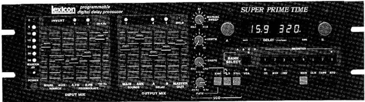
Owner's Manual
Table of contents
| SECTION ONE - INTRODUCTION | SECTION SIX - APPLICATIONS | ||||
| 3 | 1.1 | General | 22 | 6.1 | Where to use the Model 97 - Basic Setups |
| 4 | 1.2 | About This Manual | 25 | 6.2 | General Applications for Delay Lines |
| 4 | 1.3 | Precautions | 25 | 6.2.1 Flanging | |
| SECTION TWO - CONTROLS AND INDICATORS | 26 | 6.2.2 Resonant Flanging | |||
| 5 | 2.1 | General | 26 | 6.2.3 Doubling | |
| 6 | 2.2 | Front Panel | 26 | 6.2.4 Trebling | |
| 8 | 2.3 | Rear Panel | 26 | 6.2.5 Long Delay Effects | |
| SECTION THREE - INSTALLATION | 26 | 6.2.6 Echo | |||
| 10 | 3.1 | Mounting | 26 | 6.2.7 Echo with Recirculation | |
| 10 | 3.2 | Power Requirements | 26 | 6.2.8 Rhythmic Effects | |
| 10 | 3.3 | Audio Signal Connections | 27 | 6.2.9 Vibrato | |
| 10 | 3.4 | Remotely Controlled Functions | 27 | 6.2.10 Pitch Twisting Effects | |
| 11 | 3.4.1 Bypass | 27 | 6.2.11 Resonant Effects | ||
| 11 | 3.4.2 Infinite Repeat | 27 | 6.2.12 Infinite Repeat Effects | ||
| 11 | 3.4.3 Register Step | 28 | 6.3 | Chromatic Tuned Resonances | |
| 11 | 3.4.4 External Delay Sweep | 29 | 6.4 | Using Two Model 97's Modulation | |
| 11 | 3.4.5 Rate In | 29 | 6.4.1 Stereo Processing with Coupled LFO | ||
| 11 | 3.4.6 Modulation Out and In Jacks | 30 | 6.4.2 Series Connection of Two Model 97's for Compound Effects | ||
| 12 | 3.5 | Tape Store In and Out | 30 | 6.4.3 Parallel Connection of Two Model 97's for Deep Tape Phasing Effects | |
| SECTION FOUR - BASIC OPERATION OF THE MODEL 97 | 32 | 6.5 | Taking Full Advantage of the Model 97 In Recording | ||
| 13 | 4.1 | General | 32 | 6.5.1 Synchronous Register Stepping from Cues on a Multi-track Tape | |
| 13 | 4.2 | Turning On the Model 97 | 33 | 6.5.2 Using the DELAY A OUT and DELAY B OUT Jacks | |
| 13 | 4.3 | "Built-In" Effects | 33 | 6.6 | Using the Model 97 in Video and Film Post Production Audio |
| 13 | 4.4 | Calibrating the Front Panel to Any Recalled Effect | 34 | 6.7 | Localization and Image Placement |
| 13 | 4.5 | About the DELAY Time Display and Settings | 35 | 6.8 | Avoiding Echoes in Distributed Sound Reinforcement Systems |
| 14 | 4.6 | INPUT MIX Controls | 35 | 6.9 | Tips on Programming Effects for Live Performance |
| 14 | 4.7 | OUTPUT MIX Controls | 35 | 6.10 | Evolving Previously Stored Effects into New Ones |
| 14 | 4.8 | Inverting the Polarity of Recirculation and Output Signals | 35 | ||
| 15 | 4.9 | Storing, Recalling, Copying and Clearing Your Own Effects in Memory | 35 | ||
| 15 | 4.10 | Writing the Memories on Magnetic Tape (Creating a File) | 35 | ||
| 16 | 4.11 | Verifying that Memories are Accurately Stored on Tape | 35 | ||
| 17 | 4.12 | Reading a File from the Tape | SECTION SEVEN - SPECIFICATIONS | ||
| SECTION FIVE - ADVANCED FEATURES OF THE MODEL 97 | 36 | 7.1 | General Performance, Controls and Indicators | ||
| 18 | 5.1 | General | 36 | 7.2 | Interface Information |
| 18 | 5.2 | The VCO and Its Associated Functions | 37 | 7.3 | Block Diagram |
| 19 | 5.3 | Using the LFO | 38 | 7.4 | Front Panel Settings Corresponding to Factory Preset Effects |
| 19 | 5.4 | Dynamic Recirculation | |||
| 19 | 5.5 | Cross Fading Between Effects | SECTION EIGHT - IN CASE OF DIFFICULTY | ||
| 19 | 5.6 | Infinite Repeat | 40 | 8.1 | General |
| 20 | 5.7 | Using a Remote Switch to Advance through the Memory Registers | 40 | 8.2 | Until Will Not Power Up |
| 20 | 5.8 | Using Recorded Cues to Advance through the Memory Registers | 40 | 8.3 | Unit Powers Up, But Will Not Pass Audio |
| 21 | 5.9 | Remote Bypassing Switching | 40 | 8.3.1 Check Cables | |
| 21 | 5.10 | Remote Control of the LFO RATE or the VCO MANUAL SWEEP | 40 | 8.3.2 Check Other Sound Equipment in System | |
| 21 | 5.11 | Remote Control of the LFO's Modulation | 40 | 8.3.3 Check Model 97 Control and Switch Settings | |
| 40 | 8.4 | Unit Powers Up, and then "Does Its Own Thing" | |||
| 40 | 8.5 | Unit Cannot Recall Stored Programs | |||
| 40 | 8.6 | Unit Will Not Store (or Recall) Memories from Tape | |||
| 41 | 8.7 | Diagnostic Software | |||
| 41 | 8.8 | Returning Units for Repair | |||
| 41 | 8.9 | Replacement Parts | |||
| 41 | 8.10 | Limited Warranty | |||
| 43 | Blank Patch Diagrams for User Convenience | ||||
Unpacking & Inspection
Remove the Model 97 from its packing material, and SAVE ALL PACKING MATERIALS in the event it becomes necessary to reship the unit. Thoroughly inspect both the Model 97 and the packing material for indications of shipping damage, and report any damage found to the carrier.
SECTION ONE Introduction
1.1 GENERAL
The Lexicon Model 97 "Super Prime Time" is a major advancement in digital audio equipment. With it you can create, store and recall an unlimited variety of effects which you have programmed, in any sequence you like. The standard unit offers a maximum delay time of 480 milliseconds, and memory extension options let you increase that to either 960 milliseconds or 1.92 seconds -- all at full 20 kHz bandwidth.
Because it is exceptionally flexible, as well as programmable, one Model 97 can do the job of a dozen conventional signal processing units. Two separate inputs provide versatile mixing and allow for cross-connection of two delay lines for stereo - or for complex processing. Separate input mix, output mix, and delay-only outputs are provided. To ensure compatibility with virtually all professional equipment, there are standard phone jacks and balanced XLR connectors, plus a 20 dB input gain boost switch for low-level sources such as electric guitars or -10 dBV to -20 dBV line level equipment.
The Model 97 is perfect for you if you're a performing musician who needs to work out a variety of special effects prior to the show or recording session, and then have the effects instantly available. That's because, at the touch of a button, you can store all the Model 97's front panel settings in internal memories, and later recall the settings as needed, in any sequence you like. The store/recall capability is equally useful to a busy recording engineer, since it allows changing the delay effects with split second timing and unparalleled precision. There are a total of 40 storage registers, 32 of which are user programmable and 8 of which are factory preset. The presets, built-in effects, are typical versions of flanging, resonant flanging, doubling, tripling, chorusing, slap echo, short echo and long echo. You can use them "raw" or, by modifying them, you can very quickly create and store your own customized effects.
With 32 memories "on line" several users can store their own effects. Built-in trickle charged Ni-Cad batteries keep the effects in memory after the power is shut Off. However, in those instances where greater storage is required, all 32 user programmable registers (or individual banks of 8 registers) are easily transferred onto magnetic tape, either cassette or reel-to-reel. This makes it possible for you to build an effects library of unlimited size. Effects stored on tape can later be loaded back into your Model 97, or any Model 97, so you can carry the sound effects without
carrying the machine.
The Model 97 is an invaluable tool in video and motion picture production, where the speed and accuracy of switching effects makes it possible to closely track the effects with the picture. To make the job even easier, the Model 97 can be made to automatically cycle through up to 32 stored effects in sync with the program by means of cue tones applied to a spare track of the master audio tape.
We have included a number of popular, innovative features from other Lexicon delay processors, such as the ability to combine sine or square wave LFO modulation of the delay time with envelope follower modulation that tracks the input signal's amplitude, a technique which provides more realistic, less mechanical doubling and flanging effects. We have also included an infinite repeat function, selectable via the front panel or a foot switch, so performers can "capture" a phrase in the delay memory, cause it to repeat indefinitely without signal degradation, and then play against the repeating phrase. Bypass of all processing is also selectable on the front panel or via a foot switch.
Additional foot control jacks enable a performer to sweep the Model 97's delay time over a 3:1 range, and to continuously vary the LFO-modulation rate. In fact, because the rate and sweep functions are based on 0 to 10 volt scaling, synthesizers, sequencers or automation systems can be directly interfaced to the Model 97 to control the effects, adding another dimension to the concept of delay processing.
Engineers can take advantage of the remote foot switch and foot control jacks by building suitable hand controls into the mixing console. This avoids the need to reach over to the outboard equipment bay when you wish to bypass the Model 97, set it for infinite repeat, step through the memory registers, sweep the delay time, or adjust the LFO rate.
The Model 97 is further equipped with features found in no other digital delay processor. Features like dynamic recirculation, which makes it possible to achieve long decay times (by using significant amounts of feedback) without "cluttering" the sound. Instead of having new sounds continuously overlap with the sounds that are being recirculated, selecting the dynamic recirculation feature automatically reduces the amount of feedback so long as new sounds are present at the Model 97 input. When the input signal ceases, the feedback is returned to the set amount so the decay time again increases. Now, without touching a control, the
musician can play complex passages which retain their definition, yet enjoy a lingering effect after the last note.
Modulation input and output voltage jacks constitute another feature unique to the Model 97. These jacks, together with the many audio input and output jacks, make it possible to cross-couple two units for stereo or synchronized multi-channel processing.
Clearly, the Model 97 "Super Prime Time" is on the cutting edge of digital audio technology. User friendly yet fully microprocessor controlled, it is a solid, reliable unit. That's because we have been building professional digital delay lines longer than anyone else so we know the ropes. As you can see, there's a lot to this unit, so to be sure you get the most out of it, we suggest you carefully study this manual. Later, after you've had a chance to familiarize yourself with the unit, read through the manual again. The Model 97 is not difficult to use, but it is a tremendously powerful tool that deserves to be studied, experimented with, and enjoyed for its full potential.
1.2 ABOUT THIS MANUAL
Section 2 provides a very abbreviated description of the front panel controls and indicators, and rear panel features of the unit. It is OK for review. However, we recommend first reading the more detailed installation instructions in Section 3 and the operating instructions in Sections 4 and 5. Some applications and effects are covered in Section 6, while the balance of the manual covers specifications and what to do if something doesn't work.
1.3 PRECAUTIONS
The Model 97 "Super Prime Time" is not particularly delicate or fragile, as compared to other audio equipment. However, the following common-sense precautions should be observed:
-
Never connect power sources or power amplifier outputs directly to any of the Model 97 XLR connectors or phone jacks (with the exception of 0 to 10 V DC power which may be applied to specified external control jacks). The Model 97's inputs are designed for line level signals. If a guitar amplifier (or other power amplifier) is used as a signal input, then a suitable attenuation pad must be used to lower the level prior to feeding the Model 97 (about 30 to 50 dB of loss, depending upon the output voltage of the amp).
-
To prevent fire or shock hazards, never operate the Model 97 in the rain or exposed wet locations.
-
Please read the Installation instructions (Section 3) of this manual before operating the Model 97.
-
Be aware that feedback (howling) can occur when either or both of the RECIRCULATION controls is moved up (A-FB and/or B-FB). To avoid possible damage to your loudspeaker system, advance recirculation gradually. A safe practice when creating a new effect that relies heavily upon recirculation is to begin with monitor amplifier levels turned down until you are reasonably certain there is no tendency to oscillate.
WARNING
All servicing of the Model 97 "Super Prime Time" should be performed by qualified service personnel. To avoid electrical shock, remove the power cord prior to removing the covers. CMOS and other integrated circuits in the Model 97 are very sensitive to static discharge, and normally are protected when mounted in the Model 97. A technician who opens the unit and handles circuitry without following careful self-grounding and work-surface grounding procedures risks ruining expensive circuit components; such damage is not covered by warranty. Therefore, unless you are truly qualified to service the Model 97, we urge you not to even open the covers. The "magic" inside is invisible, anyway, hidden inside the specially configured, but rather ordinary looking, IC chips.
Controls & Indicators
2.1 GENERAL
The front control panel of the Model 97 is divided conceptually into two parts, the audio processor and the computer controller. While these two sections are closely related to one another, initially they may be considered as separate, independent areas.
The computer controller serves to "read" the front panel control settings, and to "command" the audio processing circuitry to follow those control settings. There are two primary operating modes, Manual and Memory. In Manual mode, the panel controls are all active, and the computer becomes "transparent," passing the control settings directly to the delay processor. Even in manual mode, however, it is the computer, not the delay processor, which operates the delay time displays and the control status LEDs. Manual mode is the equivalent to operation of a traditional, hard-wired processing device such as the Model 93 "Prime Time." In fact, those who are familiar with the Model 93 will notice that many of the controls on the left side of the Model 97 front panel serve similar functions to controls on the Model 93, though some are operated in a slightly different manner.
While in Manual mode, the operator can elect, at any time, to store the setup of the front panel controls into memory. In Memory mode, stored setups (including 32 user addressable registers and 8 factory presets) can be recalled. By recalling a memory register, you actually cause the computer to command the delay pro-
cessor to duplicate the original setup that was stored into memory; the front panel controls do not physically move, but the internal circuitry behaves as though the controls were moved. Incidentally, the 8 factory preset effects are set up as fairly general versions of common delay usage.
Once any of the stored setups has been recalled, the user can still operate the panel controls as though the unit were in Manual Mode, with a few minor differences. Pushbuttons will work normally. The rotary and slide controls, however, will be ignored until they pass through the "null" point, the position which existed at the time the setup was stored. Once the rotary or slide control passes the null point, it becomes active and is able to change the audible effect. This allows for the "editing" of a recalled effect. Setups edited in this way can be stored back into the same memory from which they were taken or into a different memory. (The presets can be edited but then must be stored in a different memory because you cannot alter the preset memory registers themselves.)
While the Model 97 is a "delay line," it actually has two separately adjustable delay times which may be mixed, but which also may be output independently. There are called the "A" and "B" delay taps.
2.2 FRONT PANEL
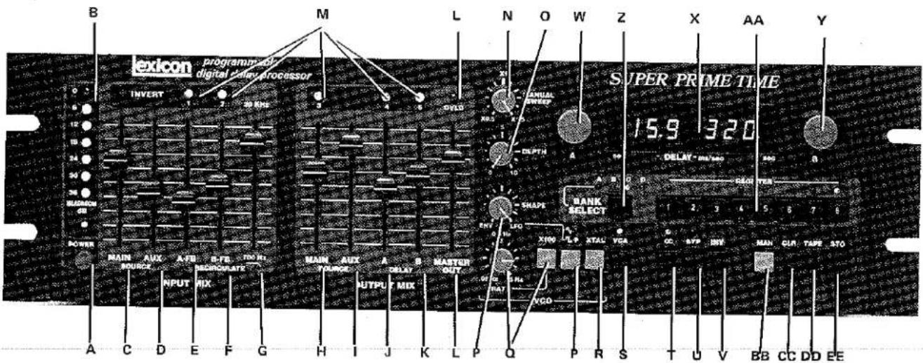
Figure 2-1 - Model 97 Front Panel
A. POWER switch
This latching pushbutton turns the AC power On and Off. When POWER is turned Off, the front panel switch and delay settings, and the memory registers are all "remembered" thanks to a rechargeable NiCad battery within the Model 97.
NOTE: The Model 97 should be left On for at least 24 hours when first purchased so that the NiCad battery charges fully. To ensure the battery remains charged, the unit should be turned On for at least 8 hours a month. (We don't expect anyone who has a Model 97 to use it less than that, anyway.)
B. HEADROOM display
The HEADROOM display monitors the audio level of the entire INPUT MIX section. The display has 7 LEDs which indicate peak levels, relative to input stage overload, from 0 dB (no headroom) to -36 dB (36 dB headroom remaining before clipping).
INPUT MIX Section
C. MAIN SOURCE control
This vertical slider adjusts the input sensitivity of the MAIN INPUT XLR and phone jack. Moving the slider up increases the level applied to the Model 97 delay processor (and to the INPUT MIX jack). This is the only front panel slider which is not memorized as part of any stored effect.
D. AUX SOURCE control
This vertical slider adjusts the input sensitivity of the AUX INPUT XLR and phone jack. Moving the slider up increases the level applied to the Model 97 delay processor (and to the INPUT MIX jack). This slider's setting is memorized as part of any stored effect.
E. A-FB control
This vertical slider adjusts the amount of RECIRCULATION (delay feedback) derived from the "A" delay tap and returned to the input. Moving the slider up feeds more of the delayed signal back to the delay processor input. Increasing the A-FB tends to sustain sounds and create resonant effects. (Too high a setting can cause loud, runaway howling.)
F. B-FB control
This vertical slider is identical to the A-FB slider, except it adjusts the amount of RECIRCULATION from the "8" delay tap.
G. Recirculation low pass filter (700 Hz - 20 kHz)
This vertical slider adjusts the cutoff frequency of a low pass filter in series with the "A" and "B" recirculation which feeds back to the inputs. All the way up, there is a 20,000 Hz bandwidth, and as the slider is brought down, the bandwidth decreases to 700 Hz. This high cut filter does not affect the main or aux signals fed to the delay processor — it only affects the recirculation components.
OUTPUT MIX section
H. MAIN SOURCE control
This vertical slider adjusts the amount of signal from the MAIN INPUT that is fed directly to the MASTER OUTPUT XLR and phone jack. (This slider is independent of the MAIN SOURCE INPUT MIX slider, and it is a programmable function.) It permits the user to blend direct MAIN input signal with the delayed, processed signals (which are adjusted with the adjacent "A" and "B" DELAY sliders).
I. AUX SOURCE control
This vertical slider is similar to the MAIN SOURCE control, adjusting the amount of signal from the AUX INPUT that is fed directly to the MASTER OUTPUT XLR and phone jack.
J. A-DELAY control
This vertical slider adjusts the amount of signal from the "A" tap of the delay line fed to the MAIN OUTPUT.
K. B-DELAY control
This is the same as the A-DELAY control, except it adjusts the "B" tap's contribution to the MAIN OUTPUT.
L. MASTER OUT control and OVLD indicator
This vertical slider adjusts the overall level of all signals at the MASTER OUTPUT XLR and phone jack. MASTER OUT is a final level control which operates on the mixed signal from the four sliders immediately to its left. If the signal level at the OUTPUT MIXER stage becomes high enough to cause clipping, the red OVLD (overload) LED above the MASTER OUT slider will turn On, indicating that one or more of the Output Mix Section sliders should be pulled down.
INVERT indicators
M. INVERT (1, 2, 3, 4 and 5)
These amber LEDs are located in the INPUT MIX section above the (1) A-FB and (2) B-FB sliders, and in the OUTPUT MIX section above the (3) MAIN SOURCE, (4) A-DELAY and (5) B-DELAY sliders. When an LED is On, it indicates that the associated slider's signal has been reversed in polarity. Polarity reversal is covered under the INV button description (paragraph V), which also explains the reason these LEDs are numbered.
VCO section
N. MANUAL SWEEP control
This pot expands and contracts the set "A" and "B" delay times over a maximum range of 3:1 (from 0.5 times the set delay to 1.5 times the set delay) — with no change in signal bandwidth.* The actual range available depends upon the DEPTH control setting; at "10" depth, MANUAL SWEEP has no effect (since the LFO is then "using up" all the delay time modulation available), MANUAL SWEEP is also defeated when the LED above the XTAL button (R) is On.
This control continuously varies the delay time, unlike the A-DELAY or B-DELAY pots, which bring about discretely stepped changes in the delay time.
*When set for maximum increase in delay time, certain loud and very high frequency signals may cause aliasing of the delay processor. Due to the Model 97's wide processor bandwidth, such distortion is rare, and would tend to occur only with unnatural signals such as a very high level upper harmonic from a synthesizer.
O. DEPTH control
This pot adjusts the amount of LFO modulation affecting the delay line (e.g., the amount of automatic variation of delay time). When DEPTH is set at "0", the LFO section does not affect the delay line. As the DEPTH control is advanced clockwise toward "10", the amount of LFO sweep increases. At "10", the LFO will sweep the delay over a full 3:1 range (whether automatic sine/square or envelope follower modulation).
P. SHAPE control, plus √ √ (sine/square) button and indicators
The SHAPE control determines the nature of automatic LFO modulation. Turned to ENV position, the LFO changes the delay times by following the envelope of the INPUT MIX signals. Turned to LFO position, the LFO changes the delay times according to a regular sine wave or square wave; the selected waveform is determined with the associated sine/square button, as shown by one of the two red LEDs above that button. The SHAPE control may be adjusted to obtain a combination of sine or square wave modulation along with envelope follower modulation.
Q. RATE control, X100 button and indicator
The RATE control adjusts the selected sine or square wave modulation over a 100:1 range. Normally, the range extends from 0.05 Hz to 5 Hz. Pressing the adjacent X100 button-once-multiples the RATE by 100 (the red LED over the button will be On) so the RATE can be varied from 5 Hz to 500 Hz. Pressing X100 a second time returns the unit to the 0.05 to 5 Hz range.
R. XTAL button and indicator
The XTAL (crystal) button allows the Model 97 delay line to be operated under crystal control, thus assuring the most stable delay time and the lowest possible distortion. Pressing the button once places the unit in crystal mode and the LED above turns On indicating that the set DELAY time will not vary. Pressing the XTAL button a second time restores normal VCO operation.
Additional Signal Processing Pushbuttons
S. VCA/FUNCTION button and indicator
This button does more than one job, depending on how it is used. Pressing VCA once will light up the red LED above the button and will place the unit in dynamic recirculation mode (which attenuates the amplitude of the recirculation signals so long as input signals are present, and automatically restores full recirculation when the input signal ceases. This effectively reduces decay time while input is applied, and lengthens decay time at the cessation of the input signal). Pressing the VCA button a second time restores the set recirculation without regard to input signal.
The VCA button also serves as a special FUNCTION button which works together with other buttons. It is used along with the REGISTER buttons when commanding the Model 97 to gradually crossfade between selected effects, or to switch immediately between effects. It is used along with the BYP and REGISTER buttons to call up special test functions and to place the unit in true crystal locked mode, as described in Sections 5 and 8.
CAUTION: Do not experiment with the test functions until reading the information in Section 8, as normal audio processing is disturbed and loudspeaker damage may be caused by the resulting output signal.
T. ∞ button and indicator
Pressing this button activates the Model 97's INFINITE REPEAT mode, capturing a brief segment of the audio input (equal to the maximum delay memory installed times the VCO sweep present at the time the button is pressed), and replaying it indefinitely with no loss of fidelity. The LED above the button is On in this mode. Pressing the button a second time cancels the repeat and restores normal signal flow through the Model 97.
U. BYP/TEST button and indicator
The BYP (bypass) button does more than one job, depending on how it is used. Pressing BYP once will light up the red LED above it and will bypass all processing in the Model 97; this is equivalent to connecting the inputs from the MAIN INPUT and AUX INPUT controls to the main output by way of the MASTER OUT control. Pressing BYP a second time restores normal processing. The BYP button also serves as a special TEST button which works together with the VCA/FUNCTION and REGISTER buttons to call up special test functions or to place the unit in true crystal locked mode. These modes are described in Sections 5 and 8. Observe-the-caution-statement accompanying paragraph "S" on the VCA/FUNCTION button.
V. INV button
The INV (invert) button is used to reverse the polarity of the signal at any of 5 points in the Model 97 INPUT MIX and OUTPUT MIX sections (refer to paragraph M). Holding the INV button in and simultaneously pressing REGISTER button #1 through #5 will invert the polarity of the correspondingly numbered function, and either turn On the amber INVERT LED (reversed polarity), or turn it Off (normal polarity).
DELAY time controls and readout
W. "A" DELAY control
Rotating this pot clockwise increases the delay time for the "A" tap on the digital processor, as shown on the left side of the DELAY readout. Delay increases in discrete steps which are automatically ranged with smaller increments at the short delay end of the scale (where high resolution is important) and larger increments at longer delay times.
X. DELAY (mS/sec) readout
This large digital LED display indicates the delay time of the "A" delay tap on the left side, and of the "B" delay tap on the right side. Each side of the readout is a 3-digit, floating decimal representation that displays from a minimum of 0.20 milli-seconds up to the maximum delay available (480 mS, 960 mS or 1.92 seconds). So that full 3-digit accuracy is preserved throughout the range, a red LED turns on above the SEC label at the edge of the display when the delay time exceeds 999 milliseconds. The readout then indicates 1.00 through 1.92 seconds.
Y. "B" DELAY control
This pot is identical to the "A" DELAY pot (W), except it adjusts the "B" tap on the digital processor, as shown on the right half of the DELAY readout. Notice that, except at the shortest and longest available delay times, the "A" and "B" delay times are intentionally set at different steps [so that richer effects "textures" are possible when the delay taps are mixed].
Memory Assignment Section
Z. BANK SELECT button and indicators
There are four user-programmable memory banks (A through D), each of which has 8 storage registers. Repeatedly pressing the BANK SELECT button steps through these four banks in alphabetical order, illuminating the red "A", "B", "C" or "D" LEDs.
Additionally, there is a fifth memory bank of 8 factory preset setups. This is accessed by holding in BANK SELECT and then pressing any one of the adjacent REGISTER buttons. All four BANK SELECT LEDs will turn Off, confirming the preset bank is selected.
AA. REGISTER buttons and indicators
Within each of the five memory banks (A - D and factory preset) are 8 discrete storage registers. To recall a given register once a bank has been accessed with the BANK SELECT button (Z), press any of the REGISTER buttons (#1 through #8). The red LED above that button will turn On to indicate your choice.
The REGISTER buttons also are used in conjunction with other Model 97 buttons, such as STO (EE) for storing panel setups, and INV (Y) for inverting the polarity of various signals. THE VCA/FUNCTION button (S) and BYP/TEST button (U) are also used in conjunction with the REGISTER buttons for special-functions. Refer to Sections 5 and 8.
Mode control buttons
BB. MAN (manual) button and indicator
Pressing the MAN button places the Model 97 in manual mode, and turns On the red LED above the button. Any setup which had been recalled from memory is now disregarded, and the processing instead will reflect the actual physical control positions of the sliders and rotary pots. Pushbuttons such as X100, sine/square, XTAL, etc. will remain in the mode they previously occupied unless they are manually changed.
MAN is also an escape button that cancels tape reading operations, as well as test routines.
CC. CLR (clear) button
This button is used in conjunction with the STO button and one of the REGISTER buttons to clear the designated register. It "erases" any setup which is in the register, and is used primarily as an end or beginning flag for remote REGISTER STEP commands (refer to Section 4.9, 5.8 and 5.9).
DD. TAPE button
This button is used to ready the Model 97 to write its solid state memories onto tape, to read taped files into the solid state memories, or to verify that the taped files indeed match the solid state memories. The specific sequence of pressing TAPE, along with other buttons, is discussed in greater detail in Sections 4.10, 4.11, 4.12 and 5.9.
EE. STO (store) button
Holding down this button and then pressing one of the REGISTER buttons (AA) will store the front panel setup in that register (provided the unit is not "parked" in the preset memory bank). The STO button also is part of the multi-button sequence used to write the contents of all 32 memories, or one bank of 8 memories, onto magnetic tape (refer to Section 4.10).
2.3 REAR PANEL

Figure 2-2 - Model 97 Rear Panel
Signal inputs and outputs
NOTE: All XLR connectors are wired as follows: pin 2 = signal high, pin 3 = signal low, pin 1 = ground. Phone jacks are wired tip high, ring low (where balanced), sleeve ground.
A. MAIN INPUT connectors and GAIN switch (0 dB / +20 dB)
This is the point where, most often, the input signal is connected to the Model 97. The XLR connector and the tip/ring/sleeve phone jack are balanced and wired in parallel. Both jacks apply line level signals to the front panel MAIN SOURCE sliders in the INPUT MIX and OUTPUT MIX sections.
Normally these inputs have a 0 dBV nominal sensitivity. Pressing in the GAIN button increases the sensitivity by 20 dB so that --20 dBV signals will drive the unit to "0" VU input level with sliders at maximum positions.
B. AUX INPUT connectors
If two inputs are to be blended, one source can be connected to the MAIN INPUT and the other to the AUX (auxiliary) INPUT. Like the MAIN INPUT, the AUX XLR connector and tfp/ring/sleeve phone jack are balanced and in parallel. Both jacks apply line level signals to the front panel AUX SOURCE sliders in the INPUT MIX and OUTPUT MIX sections. The AUX INPUTs have a 0 dBV nominal sensitivity. While AUX has a slightly lower impedance than the MAIN INPUTs, either MAIN or AUX may be used with 600 ohm or higher impedance sources.
NOTE: The MAIN INPUT has slightly better common mode rejection and lower noise than the AUX INPUT. A low level input from a guitar pickup or similar source should be applied to the MAIN INPUT.
C. UNBALANCED OUTPUT connectors (INPUT MIX, DELAY-A, DELAY-B)
These unbalanced phone jacks are intermediate line level outputs. The INPUT MIX OUTPUT carries the mixed MAIN and AUX in signals after their respective INPUT MIX sliders, as well as A-FB and B-FB signals. The DELAY-A and DELAY-B outputs carry the delayed signal directly from the "A" and "B" delay tap, with no "direct" input signal. These outputs have an actual 600 ohm source impedance, and are intended for use with 2K ohm or higher impedance inputs, which they drive to a maximum level of +10 dBV.
D. MASTER OUTPUT connectors
This is the point where, most often, the audio output is derived from the Model 97. The XLR connector is electronically balanced, with the tip/ring/sleeve phone jack in parallel. Both jacks carry the combined delay and direct signals from the OUTPUT MIX section. The outputs have an actual 200 ohm source impedance, and are intended for use with 600 ohm or higher impedance inputs. Maximum output level is +22 dBV. To drive a single-ended load, the XLR connector pin 3 or the phone jack ring must be tied to ground, preferably at the load end of the cable (for minimum noise).
Remote Control connections
E. EXTERNAL DELAY SWEEP jack
This tip/ring/sleeve phone jack is intended for use with a foot pedal (or rotary pot). It provides a means for remote control of the MANUAL SWEEP function.
An external source of 0 to +10 V DC connected across the tip and sleeve will sweep the Model 97 from minimum to maximum delay time provided the unit is not in XTAL mode, the VCO DEPTH control is turned to "0", and the MANUAL SWEEP control is turned to "X0.5".
The Model 97 supplies its own +10 V DC to the ring of the jack so that Lexicon's foot pedal may be used (or any control using a 50 kohm pot and wired so the TRS phone plug ring goes to the high side of the pot, the tip to the wiper, and the sleeve to the low side of the pot).
F. MODULATION OUT jack
This tip/ring/sleeve phone jack provides a DC voltage of 0 to +10V at the tip, corresponding to the LFO modulation signal of the Model 97's VCO. The output may be connected to another Model 97's MODULATION IN jack, or to another delay line with similar modulation scaling so that one unit's LFO serves as a master for both units. Using the output does not affect the internal function of the Model 97, so long as it is connected to a high impedance circuit.
G. MODULATION IN jack
This tip/ring/sleeve phone jack is normalled to the MODULATION OUT jack so that, when no plug is inserted, the Model 97's LFO signal is routed so it can change the delay time. When a plug is inserted in the MODULATION IN jack, the internal LFO can no longer control the Model 97 VCO. Instead, an external source of 0 to +10V can be used for this purpose.
H. RATE IN jack
This tip/ring/sleeve phone jack is intended for use with a foot pedal (or rotary pot). It provides a means for remote control of the LFO RATE.
An external source of 0 to +10 V DC connected across the tip and sleeve will change the LFO RATE from 0.05 Hz to 5 Hz provided the front panel RATE control is set to 5 Hz (5 Hz - 500 Hz if in X100 mode). If the RATE control is not at maximum, the effect of the external RATE IN jack is scaled down accordingly
The Model 97 supplies its own +10 V DC to the ring of the RATE IN jack so that Lexicon's foot pedal may be used (or any control using a 50 kilohm pot and wired so the phone plug ring goes to the high side of the pot, the tip to the wiper, and the sleeve to the low side of the pot).
NOTE: The following three jacks rely upon external switch closures. Contact ratings are insignificant because low, logic-level voltages (3 to 5 V DC) are involved.
I. BYPASS jack
This tip/sleeve phone jack provides for remotely switching the Model 97 to bypass mode. A momentary switch closure between the tip and sleeve places the unit in bypass and turns On the front panel BYP LED; a second momentary closure returns the unit to normal processing. Lexicon's foot switch, or any momentary switch, may be used.*
J. oo REPEAT jack
This tip/ring/sleeve phone jack provides for remotely switching the Model 97 to infinite repeat mode. (See Section 5.6 for details.) A momentary switch closure between the tip and sleeve places the unit in that mode and turns On the front panel oo LED; a second momentary closure returns the unit to normal processing. Lexicon's foot switch, or any momentary switch, may be used.
K. REGISTER STEP jack
This tip/ring/sleeve phone jack provides for remotely advancing the Model 97 sequentially through its memory registers. (See Section 5.8 for details.) Each momentary switch closure between the tip and sleeve advances the unit by one register. Lexicon's foot switch, or any momentary switch, may be used.
L. TAPE STORE IN jack
This tip/ring/sleeve phone jack is an unbalanced, line level input. It is used for playback of tape recorded memory files that are loaded into one or all four of the Model 97's user programmable memory banks (Sections 4.11 and 4.12). It is also used for playback of special cue tones for automatically stepping through the memory registers (Section 5.9). Only the appropriate frequency-shift keyed digital data or cue tones written with this, or any Model 97 will be recognized as valid input. While level is non-critical (-20 to +10 dBV nominal), the tape speed must be steady and correct.
M. TAPE STORE OUT jack
This tip/sleeve phone jack is an unbalanced, line level output. It is used to write ("dump") the memory files that are loaded into one or all four of the Model 97's user programmable memory banks onto magnetic tape. Only the appropriate frequency-shift keyed digital data written with this or any Model 97 will be recognized as valid input (Section 4.10). The jack is also used to output cue tones on tape for automatic stepping through the memory registers upon playback (Section 5.9). Output level is 0 dBV nominal, suitable for cassette or reel-to-reel recorders.
N. Power connector
The power connector accepts standard IEC (NEMA) power cords. Before plugging in the AC cord and applying power, check the adjacent data on the rear panel to ensure the set operating voltage matches that of the AC mains. It is a good idea to also make sure the Model 97 front panel POWER switch is off (button out) before connecting or disconnecting the AC cord.
O. FUSE holder
Units sold in the US and Canada are provided with 1/4" diameter x 1-1/4" long primary fuses; export models have 5 mm diameter x 20 mm long fuses. Internal secondary fuses are 20 mm. Replace fuses only with ones of an identical current rating.
SECTION THREE
Installation
3.1 MOUNTING
The Model 97 is designed to be mounted in a standard 19 inch relay rack, where it occupies three rack spaces (5-1/4") and extends 13" behind the front panel. If the unit is to be shipped in a rack, we suggest supporting the rear of the chassis to protect the unit from vibration and mechanical shock.
The Model 97 is fitted with rubber feet, and may therefore be rested on any flat surface. Whether in a rack or not, be sure to provide adequate ventilation around the top and bottom covers of the unit. In general, electronic equipment operates with greater stability and reliability when kept cool.
Since the Model 97 processes low level audio signals, it is advisable to locate it away from strong electromagnetic fields such as those generated by power transformers, motors, fluorescent ballasts, etc.
3.2 POWER REQUIREMENTS
The Model 97 is set at the factory to operate from either 100, 120, 220 or 240 volts (50 Hz or 60 Hz); the factory set voltage is indicated on the rear panel. The unit draws a maximum of 50 watts. Units set for 100 or 120 volts are fused at 1/2 ampere, while 220 and 240 volt units are fused at 1/4 ampere.
The nominal line voltage can be changed from whatever value is factory preset. However, NO CHANGE SHOULD BE MADE EXCEPT BY A QUALIFIED SERVICE TECHNICIAN. The line voltage is determined by a pair of changeover switches located at the left rear of the chassis, behind the power transformer. Making sure the AC power cord is first unplugged, the cover may be removed to reveal these switches. They are set for the desired voltage, as shown in Figure 3-1. Then the cover is replaced, and, if necessary, the line cord is changed and the primary fuse is changed to an appropriate value. We strongly recommend that a label be affixed to the rear of the unit indicating the new line voltage.
The power cord supplied with the Model 97 utilizes a standard IEC connector, simplifying adaptation to power sources in various countries. The AC cord provides chassis grounding to the mains ground in order to comply with accepted safety standards (i.e., it is a 3-wire cord).
3.3 AUDIO SIGNAL CONNECTIONS
All unbalanced audio input and output jacks on the Model 97 accept 1/4" tip/ring/sleeve phone plugs. The ring is automatically grounded. All XLR connectors and parallel phone jacks are electronically balanced by means of differential amplifiers. Be sure you are using the proper plug and cable for a given connection. (Refer to the discussions in Section 2.3, and to Figure 3-2 below.) The Model 97 is not intended for use with microphone-level signals, although certain high-output condenser mics and guitar pickups may provide adequate drive level for the MAIN INPUT when the GAIN button is engaged. (Even if a guitar will drive the Model 97 directly, using a guitar preamp is a good idea
trols. Bear in mind that the input level from the MAIN INPUT is not "memorized" when a front panel setup is stored, whereas the AUX INPUT level is memorized. Therefore, if you want the input settings to be "remembered", use the AUX INPUT.
WARNING
Never connect the Model 97 MAIN or AUX inputs directly to power sources, improperly isolated AC/DC devices, or power amplifiers. Disregarding these precautions can lead to electrical shock and may do permanent damage to the Model 97.
While the Model 97 audio outputs are protected against short circuits, they should never be connected to signal sources.
3.4 REMOTELY CONTROLLED FUNCTIONS
Three rear panel phone jacks permit remote switching of the BYPASS, INFINITE REPEAT and REGISTER STEP functions. Additional phone jacks permit remote control of the DELAY
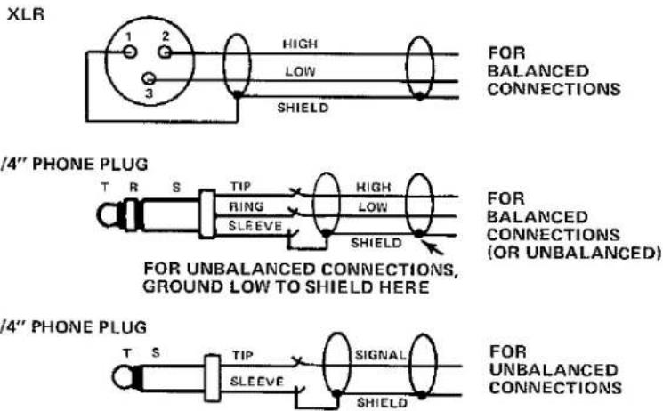
Figure 3-2 - Typical Wiring of Audio Input and Output Connections
due to the extra tonal control then available.) If any of the Model 97 outputs is connected to a mic input, a 50 dB attenuation pad should be used.
MAIN and AUX INPUT connections are provided so that two sources can both be connected to the Model 97, and mixed using the front panel con-SWEEP and LFO RATE. For performing musicians, foot switches and foot controllers are available from Lexicon. Additionally, many commercially available switches and controllers may be used, or units can be built using the information in this sub-section of the manual. For recording or broadcast engineers wishing to control these functions from the mixing console, switches and rotary or slide controls can be built into the console.
Two additional phone jacks are provided, the VCO modulation input and output. These jacks permit one Model 97's VCO to control another. These jacks also permit the Model 97 to be modulated by external 0 to 10 volt sources such as a synthesizer's
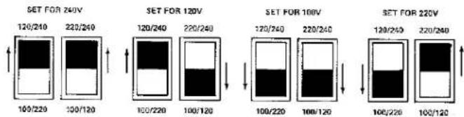
Figure 3-1 - Setting the Voltage Changeover Switches
keyboard voltage (directly or via a sequencer) or a mixing automation system.
One further remotely controlled function is available, the stepping through registers triggered by cue tones on tape. This is accomplished using the TAPE STORE jacks, and is discussed in Section 3.5.
3.4.1 BYPASS
In BYPASS mode, the INPUT MIX signal (aux plus main inputs, not feedback) is routed to the main output via the MASTER OUTPUT level control; all processing is bypassed except the MAIN INPUT LEVEL, AUX INPUT LEVEL and MASTER OUTPUT LEVEL settings. The BYPASS jack accepts a standard 1/4" tip/ring/sleeve phone plug or a tip/sleeve phone plug. BYPASS is activated by a momentary remote switch closure which grounds the tip to the sleeve, and is cancelled by a subsequent switch closure.
3.4.2 INFINITE REPEAT
The INFINITE REPEAT function allows permanent retention of any sound in the delay memory. The REPEAT jack accepts a standard 1/4" tip/ring/sleeve phone plug or a tip/sleeve phone plug. REPEAT is activated by a momentary remote switch closure which grounds the tip to the sleeve. The program segment retained in memory is that program which was in the memory prior to the switch closure. REPEAT is cancelled by a subsequent switch closure.
3.4.3 REGISTER STEP
The REGISTER STEP function allows the operator to sequentially select stored effects. The REGISTER STEP jack accepts a standard 1/4" tip/ring/sleeve phone plug or a tip/sleeve phone plug. Each time a remote switch closure momentarily grounds the tip to the sleeve, the selected memory register will index by one unless there is a "blank" memory; then the unit will return to either the #1 register in that memory bank or, if there is another "blank" memory stored in the bank, the unit will return to the register following the previous "blank". In the absence of "blank" memories, continuing switch closures will sequence to the next bank, and will step through all 32 user-programmable registers.
3.4.4 EXTERNAL DELAY SWEEP
The EXTERNAL DELAY SWEEP jack allows remote operation of the VCO, essentially duplicating the front-panel MANUAL SWEEP function. The more DEPTH selected for LFO modulation, the less effect available from this jack. The EXTERNAL DELAY SWEEP jack accepts a standard 1/4" tip/ring/sleeve phone plug. Full sweep range is achieved by applying from 0 to 10 volts across the tip and sleeve of the jack. For those instances where an external 10 volt source is not used, the Model 97 provides its own 10 volt source on the ring of the jack. (While the 10 volt output is current limited for burn-out protection, tip/sleeve phone plugs should be avoided since they will overload the internal 10 volt supply). Increasing the voltage across the tip and sleeve from 0 to 10 volts will sweep delay time for a given front-panel DELAY setting from minimum (equivalent to X0.5) to maximum (equivalent to X1.5) provided that (a) the unit is not in XTAL mode, (b) VCO DEPTH is turned to "0", and (c) the MANUAL SWEEP control is turned to "X0.5".
3.4.5 RATE IN
The RATE IN jack allows remote control of the LFO modulation rate, essentially duplicating the function of the front-panel RATE control. The RATE IN jack accepts a standard 1/4" tip/ring/sleeve phone plug. Full sweep from 0.05 Hz to 5 Hz (or from 5 Hz to 500 Hz if the front-panel X100 scale is selected) occurs as the voltage across the tip and sleeve is increased from 0 to 10 volts assuming (a) the front panel RATE control is set at maximum, (b) the unit is not in XTAL mode, and (c) VCO DEPTH is turned to "10". Like the EXTERNAL DELAY SWEEP jack, RATE IN provides its own 10 volt source on the ring of the jack for use when an external 10 volt source is not available (e.g., for use with a foot controller rather than a synthesizer keyboard voltage or an automation system).
3.4.6 MODULATION OUT and IN jacks
MODULATION OUT is a tip/ring/sleeve phone jack with a DC voltage of 0 to +10V across the tip and sleeve, corresponding to the LFO modulation signal generated by the Model 97's sine/square oscillator and envelope follower. Tip/sleeve or tip/ring/sleeve phone plugs may be used. MANUAL SWEEP or EXTERNAL SWEEP modulation that might also affect the Model 97 VCO is not part of this modulation output. In fact, even if XTAL mode is selected and the Model 97 is not affected by its own VCO, the MODULATION OUT jack still carries a signal that corresponds to the setting of the front-panel LFO controls. This output may be used without affecting the internal operation of the Model 97 (so long as it is connected to a 2K ohm or higher input).
MODULATION IN, also a tip/ring/sleeve phone jack, is normally connected internally to MODULATION OUT so that the Model 97's LFO modulation signal can reach its VCO. When a tip/sleeve or tip/ring/sleeve phone plug is inserted in the MODULATION IN jack, the internal signal path is broken and instead whatever voltage is present across the tip and sleeve of the plug will be applied to the Model 97's VCO.
Typically, MODULATION OUT of one Model 97 is patched to MODULATION IN of a second Model 97 when stereo signals are being processed and the same LFO modulation is desired for both channels. In such cases the audio itself is discrete, but the delay time changes track each other. The Model 97 whose MODULATION IN jack is used becomes a "slave," its LFO controls having no effect, and the Model 97 whose MODULATION OUT jack is used becomes a "master," its LFO controls setting both units.

Figure 3-3 — Remote Switch and Controller Schematic Diagrams This diagram can be used to construct foot switches and foot controllers for the Model 97, or panel-mounted switches and controls. The potentiometers should be rated at approximately 50,000 ohms with a linear taper. For any portable application, especially foot controllers, cables should have braided or spiral shielding (not foil) and stranded conductors, and a tough outer jacket. Avoid cable lengths exceeding 15 feet (5 meters).
NOTE: At first glance, MODULATION IN might seem to duplicate the EXTERNAL DELAY SWEEP function, but it is different. True, a 0 to 10 volt signal across MODULATION IN will sweep the delay time much the same way that it would do at EXTERNAL DELAY SWEEP. However, the EXTERNAL DELAY SWEEP function can be blended with built-in LFO modulation when the front-panel DEPTH control is not at the extremes of its rotation, while use of the MODULATION IN jack precludes blending of the external signal with any built-in LFO modulation. Moreover, 10 volts is available at the EXTERNAL DELAY SWEEP jack for use with foot controllers, etc., while MODULATION IN provides no such voltage; it must come from an external source.
3.5 TAPE STORE IN AND OUT
The TAPE STORE jacks have multiple functions. These tip/ring/sleeve phone jacks send data to a tape recorder (TAPE OUT), and receive it from a tape recorder (TAPE IN) for the purpose of permanently storing the Model 97's memory registers and retrieving them later. Additionally, the TAPE STORE OUT of one Model 97 can be connected to the TAPE STORE IN of another Model 97 so that memory contents can be "dumped" directly from one unit to the other without using a tape recorder. There is one further use of these jacks: automatic register stepping. When the unit is placed in the appropriate operating mode (Section 5.9), the Model 97 TAPE OUT jack will carry a cue tone each time the front-panel TAPE button is pressed, and the unit will also step to the next memory register. Upon playing back the tape
with the cue track output connected to the Model 97 TAPE IN jack, each occurrence of the cue tone will cause the unit to step to the next memory register. Once again, this automatic step function can be performed without tape by connecting TAPE OUT from one Model 97 to TAPE IN of the next unit, provided both are set to the proper mode; such operation is handy when using two units in tandem for stereo processing, since only one unit need be operated to sequence both of them.
The audio input and output at these jacks is unbalanced, applied to the tip and sleeve of any tip/ring/sleeve plug (tip/sleeve phone plugs may be used, too). The line-level signal present at TAPE OUT varies. There is frequency-shift keyed data when storing effects, a momentary frequency shift code for cue "register step automation" purposes, and a steady tone at all other times.

4.1 GENERAL
This section describes how to "power up" the Model 97, how to immediately obtain useful effects, and how to store and recall your own effects — in the Model 97's 32 solid state storage registers and on tape for expanded, long-term storage. After familiarizing yourself with these basic functions, be sure to consult Section 5, which covers more advanced features and functions, and Section 6, which describes applications.
4.2 TURNING ON THE MODEL 97
The Model 97 has no special "powering up" requirements, but should be treated with the same care given any audio signal processing device. When driving any power amplifier/loudspeaker system, the power amp should be turned On after the Model 97, and turned Off before turning Off the Model 97, and the amplifier volume should initially be turned down. This precaution will avoid the chance of damaging a loudspeaker in the event of a Model 97 malfunction (or an improper setup); under normal operating conditions, there should be no large "thump" when switching On the Model 97.
While the Model 97 may be used immediately, we suggest allowing 5 minutes for the VCO (voltage controlled oscillator) to warm up. This ensures the accuracy of recalled effects, and also provides stability so that newly programmed effects will remain constant.
4.3 "BUILT IN" EFFECTS
The Model 97 is equipped with eight "built-in" factory preset effects. These basic digital delay programs are combinations of front panel settings which are permanently stored in the solid state memory. While the presets themselves cannot be user altered, they can be recalled, slightly or extensively modified, and then stored in other memories.
Notice that the BANK SELECT button has four LEDs associated with it, labeled "A", "B", "C" and "D" corresponding to the four banks of 8 memory registers which you can use to store and recall your own programmed effects. A fifth memory bank contains the 8 factory preset effects, and is accessible by pressing in the BANK SELECT button, holding it in, and then pushing any one of the REGISTER buttons (1 to 8).
Once you have accessed the preset memory bank, you will see that all BANK SELECT LEDs are Off (indicating you are working with the preset memory bank). You can now select any of the 8 factory preset effects by simply pressing the desired REGISTER button (1 to 8). You need not press BANK SELECT again.
| REGISTER | Effect |
| 1 | Basic Flange |
| 2 | Resonant Flange |
| 3 | Doubling |
| 4 | Trebling (doubling with both delay taps) |
| 5 | Chorus |
| 6 | Slap Echo |
| 7 | Moderate Echo |
| 8 | Echo with Recirculation (feedback) |
In review, to access the factory preset effects:
-
Press BANK SELECT and hold it in.
-
Press any one of these 8 REGISTER buttons:
| 1 | 2 | 3 | 4 | 5 | 6 | 7 | 8 |
-
Release the above buttons.
-
To access another preset, press another REGISTER button.
The factory presets are intentionally bland, "middle of the road" effects. They are jumping off points for you to create your own, custom tailored effects, as described in the following paragraphs.
4.4 CALIBRATING THE FRONT PANEL TO ANY RECALLED EFFECT
When you recall a programmed effect from one of the factory preset memories (or later, one of your own stored effects), most of the Model 97 front panel control and switch settings are ignored. Instead, the microprocessor "sets" these controls internally. If the front panel feature is a switch with an associated LED, you can observe the recalled setting by observing that LED. However, you won't know the recalled setting when looking at the slide or rotary controls.
There is a simple method for you to determine the exact settings you've recalled. First, recall one of the preset effects (as described in Section 4.3). Grasp any slide or rotary control, and slowly move it toward minimum or maximum setting while looking at the DELAY display. The control will have no effect until it reaches the setting equal to the stored setting; AT THIS "NULL" POINT THE DELAY TIME DISPLAY WILL FLASH OFF FOR AN INSTANT. (If moving the control to one extreme did not cause the display to flash, move it all the way to the other extreme.)
Once the display flashes, the control you're moving becomes active, and further adjustments will change the effect. If you don't want to change the effect but you accidentally overshoot the "null" setting, just press the appropriate REGISTER button again; the initial effect will again be recalled, and you can repeat the calibration process (it will not be necessary to re-calibrate any controls which are already at their null points).
This technique is particularly useful when you recall an effect that you don't remember how you achieved (or one that somebody else programmed). For reference, you can write down the settings using one of the blank front panel diagrams in the back of this manual. (Preset effects are shown in Section 7.)
4.5 ABOUT THE DELAY TIME DISPLAY AND SETTINGS
The DELAY displays consist of two sets of large 3-digit, floating decimal point LED readouts (For the "A" and "B" delay taps). Each readout is capable of displaying delay times ranging from 0 mS (zero milliseconds) up to 960 or 1,920 mS (1.92 seconds), depending on the memory option installed in the Model 97. Times above 999 mS, however, will be displayed in seconds, not milliseconds, to preserve greater resolution. The decimal point automatically moves, and an adjacent "sec" (seconds) LED lights to signal the readout has changed from milliseconds to seconds.
The rotary controls on either side of the display adjust the "A" and "B" delay times, and are independent of one another. The response of these controls is tapered so that very fine resolution is available at the shortest delay times, with broader resolution at longer times.
The delay time is adjusted in increments which provide greater resolution at shorter times. Also, except at the shortest and longest times, the "A" and "B" taps cannot be set to the identical delay time; odd delay times are set by the "A" tap and even times by the "B" tap. This intentional offset is done to create satisfying reverberant ambience by providing non-related delay times in the two outputs. It also prevents "dithering" (a digital noise). The specific delay times available are determined by the way the Model 97 software was written.
4.6 INPUT MIX CONTROLS
The Model 97 front panel has two sets of vertical slide faders, each in a blue box: one box is marked "INPUT MIX" and the other "OUTPUT MIX." Five INPUT MIX controls adjust the input signal supplied to the digital delay processor: MAIN and AUX SOURCE levels (from input connectors), A-FB and B-FB controls (RECIRCULATE), and a variable 6 dB/octave low pass filter which adjusts the recirculation signal bandwidth from 20 kHz down to 700 Hz.
The MAIN SOURCE control is the only front panel control on the Model 97 whose settings are neither stored nor recalled. This is so that different signal levels at the Model 97 MAIN INPUT can be accommodated without any need to alter the programmed effect. If you prefer to store the input level setting, use the AUX SOURCE control and connect the signal to the Model 97 AUX INPUT. (When two separate input signals are brought to the MAIN and AUX inputs, the MAIN and AUX SOURCE controls in the INPUT MIX section may be used to blend these signals in any desired proportion.) The preferred input, when only one is needed, is the MAIN INPUT.
The HEADROOM display should be observed when adjusting any of the INPUT MIX controls. Only on the loudest peaks should the red "0 dB" LED be allowed to turn ON; average signal levels should be in the "6 dB" to "18 dB" range. Excessive levels will lead to distortion, and, at higher frequencies and longer delay times, may cause aliasing.* Very low signal levels cause unnecessary degradation of the signal-to-noise ratio; if low effects levels are needed, turn the Model 97 OUTPUT level down. On the other hand, in the event low level signals are used to drive the Model 97, remember that a rear panel pushbutton can be engaged for an additional 20 dB of GAIN at the MAIN INPUT connector. (The 20 dB button, and the INPUT MIX controls all affect the level fed to the INPUT MIX OUTPUT jack, which will deliver about +10 dBV, at "0 dB" on the headroom display, into 2 kohm or higher impedance loads.)
Feedback, or recirculation, is adjustable independently for the A and B delay taps. High levels of recirculation will lead to a loud, sustained howl that, in turn, could damage loudspeakers so go easy when bringing up to the A-FB and B-FB sliders.
The low pass filter simultaneously adjusts the bandwidth of both the A and B recirculation. While 20 kHz is available, more natural effects will generally be obtained with a lower cut-off frequency. This is because, in actual echoes, the longer the path of the sound, the more the air attenuates higher frequencies. (Lower frequencies are not attenuated as much.) Depending on the program material, lowering the filter slider may enable you to raise the A-FB and B-FB sliders higher before howling occurs, thus effectively increasing the practical echo duration as a tradeoff against recirculation bandwidth.
4.7 OUTPUT MIX CONTROLS
The OUTPUT MIX controls adjust the relative amount of delayed (processed) and "direct" source signals that appear at the Model 97 MASTER OUTPUT. There are four independently adjustable level controls plus a master: MAIN and AUX SOURCE levels (from input connectors), A and B DELAY controls (the processed signals), and MASTER OUT. The settings of all these controls are memorized when an effect is stored.
The relationship between the INPUT MIX and OUTPUT MIX controls is shown in Figure 4-1. Note the difference between the MAIN and AUX controls in the INPUT MIX section (these determine what signal is sent to the delay processor), and the MAIN and AUX controls in the OUTPUT MIX section (these determine what amount of those same input signals are sent, unprocessed, directly to the MASTER OUTPUT connectors).
The HEADROOM display is not affected by the OUTPUT MIX controls. However, when the signal level becomes high enough to cause clipping of the output stage, the red OVLD (overload) LED above the MASTER OUT control will turn On. Even when OVLD is not illuminated, it may be possible that the Model 97 outputs will overdrive the equipment to which they are connected. Therefore, we recommend checking the specifications of that equipment to make sure the gain structure is suitable. If using equipment with -10 to
-20 dBV sensitivity, it may be desirable to install an attenuation pad after the Model 97 output rather than operate with the OUTPUT MIX controls at very low settings.
NOTE: The Model 97 MASTER OUTPUT delivers up to +22 dBV into 600 ohm or higher balanced loads or +16 dBV with unbalanced loads. The DELAY A and DELAY B "direct" outputs deliver up to +10 dBV into 2 kohm or higher impedance loads.
4.8 INVERTING THE POLARITY OF RECIRCULATION AND OUTPUT SIGNALS
Notice that there are five numbered, amber LEDs above various INPUT MIX and OUTPUT MIX controls: (1) A-FB, (2) B-FB, (3) MAIN SOURCE, (4) A DELAY, (5) B DELAY. The signal polarity at the circuit point following each of these five controls can be inverted, and when it is, the corresponding amber LED will be illuminated. To invert (or un-invert) the polarity, press the INV button and, while holding it, press REGISTER button #1 through #5 (corresponding to the number below the amber LED of the control whose polarity you wish to invert). Repeating the 2-button sequence will toggle the polarity.
As an example, if you want to invert the polarity of the "A DELAY" OUTPUT MIX control:
-
Press INV and hold it in.
-
Press the #4 REGISTER button, which corresponds to amber LED #4 over the "A DELAY" control.
| 1 | 2 | 3 | 4 | 5 | 6 | 7 | 8 |
*Aliasing is a non-linear distortion in which the digital signal processor creates lower frequency components which have a strange and usually unpleasant relationship to the input signal.

flowchart
graph TD
    A["MAIN IN"] --> B["INPUT MIX"]
    C["AUX IN"] --> B
    B --> D["LOW PASS FILTER"]
    D --> E["DELAY LINE"]
    E --> F["OUTPUT MIX"]
    G["HEADROOM DISPLAY"] --> E
    H["OVLD LED"] --> F
    I["MASTER OUT LEVEL"] --> F
    J["MASTER IN"] --> B
    K["BF8"] --> B
    L["AFB"] --> B
    M["A"] --> E
    N["B"] --> E
Figure 4-1 - Input and Output Mix Section Block Diagram
- Release the above buttons, or ...
- To invert another function, continue
holding INV and press another
REGISTER button.
4.9 STORING, RECALLING, COPYING AND CLEARING YOUR OWN EFFECTS IN MEMORY
NOTE: We have intentionally "skipped" a discussion of the controls labeled VCO (MANUAL SWEEP, DEPTH, SHAPE, RATE, X100, sine/square, and XTAL). These important functions, which are used to create many of the Model 97's special effects, are discussed in detail in Section 5. For now, let's explore how to store and then recall effects.
An effect, as defined here, is any combination of front panel control settings, with a few exceptions. As stated earlier, the Model 97 will not memorize the setting of the MAIN SOURCE control in the INPUT MIX section.
For reasons that should become obvious, neither will it store MAN, CLR, TAPE or STO button settings. MAN places the controls in manual mode, not subject to memory. CLR, TAPE and STO are used when "dumping" the solid state memories onto magnetic tape (or retrieving them); the buttons do not directly have anything to do with a particular effect.
To store an effect into memory:
- Select the memory bank desired, A through D, by repeatedly pressing

-
Press STO and hold it in
-
Press any one of the 8 REGISTER buttons corresponding to the #1 through #8 memories in the selected bank
| 1 | 2 | 3 | 4 | 5 | 6 | 7 | 8 |
To recall an effect from memory:
- Select the memory bar desired, A through D, by repeatedly pressing

- Press the REGISTER button corresponding to one of the 8 memories in which the desired effect is stored
| 1 | 2 | 3 | 4 | 5 | 6 | 7 | 8 |
To copy an effect just recalled into another memory register:
- Select the memory bank desired, A through D, by repeatedly pressing (not needed if already in correct bank).
- Press the STO button.
- Press any of the 8 REGISTER buttons to designate the memory into which you want to copy the effect.
| 1 | 2 | 3 | 4 | 5 | 6 | 7 | 8 |
You have now stored the effect in this second memory -- it is still "in effect" in the processor, and also exists in its original memory location.
It is not necessary to clear a memory if you want to store a new effect in it. However, clearing is necessary when you intentionally want a "blank" memory, as you may need when using a REGISTER STEP footswitch or when using tape recorded cue tones to step through memories (as described in Section 5).
To clear a memory register:
- Select the desired memory bank, as described above.
- Press CLR and hold it in
- Press the REGISTER button(s) corresponding to any of the memories you wish to clear
| 1 | 2 | 3 | 4 | 5 | 6 | 7 | 8 |
NOTE: As long as CLR or STO is held in, as many registers as desired may be stored or cleared (within a given bank). The STO and CLR buttons will not function when the factory preset bank has been selected (i.e., when none of the BANK SELECT LEDs is illuminated).
4.10 WRITING THE MEMORIES ON MAGNETIC TAPE (CREATING A FILE)
When you store effects in any of 32 locations (i.e., banks A through D times registers 1 through 8), you are actually placing digital information in solid state memories. Because the Model 97 includes a rechargeable back-up battery, its memories can be considered non-volatile. Still, there are reasons to store the contents of the memories in other permanent, non-volatile location — on magnetic tape.
Off-loading memories onto tape ("writing a file" onto tape) makes it possible to have an unlimited repertoire of stored effects. When storing the contents of the memories on tape, digital data is output as two frequency-shifted modulated tones, requiring less than 3 kHz bandwidth, so the demands on the tape recorder's frequency response are not severe. However, the recorder should have reasonably good record/play speed stability (as well as low wow & flutter).
You can choose to write all 32 effects on tape, or only one of the banks. You also have a choice of labeling the stored bank or banks with a one or two digit number; when sequentially writing different groups of memories onto tape, such numeric flags become useful. That's because the Model 97 can later be instructed to "ignore" all but the one numbered file you are seeking as you play a tape with several different files.
NOTE: It is generally faster to log the tape time at which a particular file is located, and wind directly to that point, or just before it. The numerical ID then assures the proper file will be read into the Model 97. We also recommend slating a vocal label on the tape just ahead of the digital effects file to help you identify it.
NOTE: It is assumed the TAPE STORE OUT jack is connected to the line input of a suitable tape machine for this procedure.
To store all 32 memory registers onto tape (unnumbered):
- Press TAPE and hold it in.
- Press STO once, then release both.
This readies the Model 97 for writing the memories onto tape. - Place the tape machine in record mode, and roll tape.
- Press TAPE once more to
initiate the write process.
The front panel DELAY display will go blank while the tape is being written, which takes about a minute and a quarter (approximately 75 seconds). During this time the Model 97's audio processing is not disturbed; however, the effect cannot be changed until after the display turns itself back On, indicating the "tape store" operation is completed. The Model 97 memories are merely copied onto tape. The effects continue to reside in solid state memory until the registers are cleared manually or until some other effects are recalled from tape.
To store all 32 memory registers in a numbered file:
-
Press TAPE and hold it in.
-
Press STO once; then, while
still holding in TAPE, release
sto and press the number you
designate N or N N
N refers to any of the 8
REGISTER buttons you use to enter a one or two digit ID number, from #1 to #88).
-
Place the tape machine in record mode, and roll tape.
-
Press TAPE once more to
initiate the write process.
To store one bank of 8 memory registers onto tape:

-
Press BANK SELECT until the desired LED(A, B, C, D) is On.
-
Press TAPE and hold it in.
- Press STO once; then release
it and, while continuing to hold in
TAPE, press BANK SELECT. Note
that the selected BANK LED remains On; this step prepares the Model 97 to store just that one bank.
- (optional) If you wish to label the
bank, continue holding in TAPE
and press any one or two REGISTER buttons (1 through 8) to designate the numerical flag.
-
Release the TAPE button.
-
Place the tape machine in record mode, and roll tape.
-
Press TAPE once more to
initiate the write process.
4.11 VERIFYING THAT MEMORIES ARE ACCURATELY STORED ON TAPE
A steady pilot tone is present at the Model 97 TAPE STORE OUT jack except when actually writing memories onto tape. If this tone is recorded and, upon playback sounds "shaky" (i.e., if there is an audible waver), then the tape machine performance is probably inadequate for reliable memory storage. However, there is a more precise way to check any given memory "dump," so that any tape dropout, noise, level deviation or "glitch" which might have interfered with the writing onto tape can be discovered before any Model 97 memories are cleared or changed.
Immediately after writing memories onto tape, perform the following verification procedure, which compares the tape recorded memory with the solid state memory. A visual indication is provided if the Model 97 memory contents are not identical to the tape recorded data. Therefore, it is best not to change any Model 97 front panel settings (and certainly do not store any modified or new effects into memory) until after performing this procedure.
NOTE: It is assumed the TAPE STORE IN jack is connected to the line output of the tape machine for this procedure.
To verify the accuracy and readability of "memory" tape:
-
Rewind the tape to a point just before the stored effects memories.
-
Press TAPE and, while holding
it in, press CLR .
- If the memories were identified by a numerical flag, also press the corresponding REGISTER number(s) while
still holding in TAPE
-
Release TAPE
-
Place the tape machine in play mode, and then press the Model 97
TAPE button again to initiate
the comparison process. The Model 97 will read the tape in the normal fashion,
but will not place the taped data into its memories. If all data on the tape agrees with the solid state memories, the unit returns to normal display and normal operation at the end of the process.
-
IF ERRORS ARE FOUND, THE MODEL 97 DISPLAY WILL SHOW A MESSAGE "EC__". The two-digit code displayed after "EC" depicts the quantity of discrepancies found. (Obviously, if you changed a memory prior to checking the tape, there will be a lot of errors.)
-
If there were errors,

twice to return to normal
operation. Check the tape and the tape machine to discover and remedy the source of the errors. Look for dirty heads, dropouts, level problems, and speed or frequency response anomalies. Then try re-writing the memories on tape and again verify the accuracy.
4.12 READING A FILE FROM THE TAPE
If no numerical flag is entered as part of the read instruction, the Model 97 will read the first file it is fed, whether numbered or not. If a numbered file is specified, then the unit will ignore all files on tape until it sees the designated one or two digit label at the front of the tape recorded file. Since it does take over a minute for each tape file to play back, asking the Model 97 to search through a tape for a given file may take a while; it is faster to note the approximate tape location where a given file is located, fast wind to that point, and then read the file into the Model 97 as indicated below.
NOTE: It is assumed the TAPE SOURCE IN jack is connected to the line output of the tape machine for this procedure.
To read a file of 32 effects from tape:
- Rewind the tape to a point a few seconds ahead of the stored effects memories.
- Play the tape.
- If you wish the 97 to read the first file that comes along,

- If you wish the 97 to read only a
designated file, hold in TAPE ,
then press the file number N
or N N using the
appropriate REGISTER button(s).
Then release TAPE and press it.
once more.
- While the tape file is being "read" into memory, the Model 97 display will show the letter "C".
NOTE: If you want to abort the tape reading operation at any point while it is in progress,

To read a single-bank file from tape: The procedure is identical to that just described for a 32 register file, numbered or unnumbered. The only difference is that the Model 97 must first be set to the bank into which you want the taped file to be read. When you store a single-bank file, the tape does not "know" whether you took it from bank A, B, C or D. Therefore, you must designate which bank the file is to be read into by presetting BANK SELECT to the bank of your choice.
5.1 GENERAL
This section assumes you are familiar with Section 4 (Basic Features). We use the term "advanced" advisedly because all the Model 97 features are technically advanced. Like taped storage of effects, the features described here are found either less often, with less sophistication, or not at all in other delay processors.
5.2 THE VCO (VOLTAGE CONTROLLED OSCILLATOR) AND ITS ASSOCIATED FUNCTIONS (MANUAL SWEEP, XTAL MODE, AND THE LFO SECTION)
The VCO has one basic function; it serves as the master clock for the audio processor. If the clock frequency (the VCO output) changes, so too will the delay times you have set with the "A" and "B" DELAY controls. (Setting the Model 97 to XTAL mode crystal controls the VCO frequency so the delay times are ultra-stable.) Many effects depend upon changing the delay time, and for this reason the VCO can be modulated by one of two primary means, either by MANUAL SWEEP or automatically by the LFO (Low Frequency Oscillator). Refer to Figure 5-1.
Turning MANUAL SWEEP is not quite the same as simultaneously turning the DELAY times up and down. Whereas adjusting the DELAY time controls alters the location in memory from which the digitally stored audio is read, adjusting MANUAL SWEEP simply changes the rate at which data moves through the memory. The maximum sweep available covers a 3:1 range, from 0.5 to 1.5 times the set DELAY. (Note that MANUAL SWEEP also causes the A and B delay times to change smoothly and continuously rather than in discrete steps, as occurs when you adjust the individual DELAY controls.) Since the clock frequency itself is altered, the maximum available delay time can be increased beyond the nominal "memory option" installed in the unit. For example, suppose you purchase the Model 97 with option #2 (full memory extension) having a maximum of 1.28 seconds DELAY. That 1.28 seconds is present only when the VCO is in XTAL mode, or when MANUAL SWEEP is centered at "X1"; moving MANUAL SWEEP to "X1.5" will result in a 1.92 second delay (1.5 x 1.28 seconds = 1.92 seconds).
MANUAL SWEEP can be used to "fine tune" delay times, or to manually adjust flanging, echo or pitch twisting effects. The available range for MANUAL SWEEP is not always the 3:1 range indicated on the control; it depends on the LFO DEPTH setting. At a DEPTH setting of "10", there is no MANUAL SWEEP at all (because the LFO is providing all the VCO modulation). At a "0" DEPTH setting, the full 3:1 MANUAL SWEEP is possible.
To obtain automatic delay time modulation, the LFO is provided. It changes the delay time over the same range as the MANUAL SWEEP, only you don't have to keep moving a knob for the change to continue. The LFO consists of two basic rotary controls (SHAPE and RATE), along with two pushbuttons (X100 and sine/square).
Pressing the XTAL button defeats the entire VCO section (LFO and MANUAL SWEEP) and fixes the delay time scaling at 1 times the DELAY display setting. This is accomplished by controlling the oscillator frequency with a quartz crystal.
More often, you'll probably want to modulate the delay times; LFO modulation is essential for many effects (flanging, phasing, doubling, chorus, etc.). If the unit is in XTAL mode, just press the XTAL button again so the LED above that button turns Off. Then you can set up the VCO as desired.
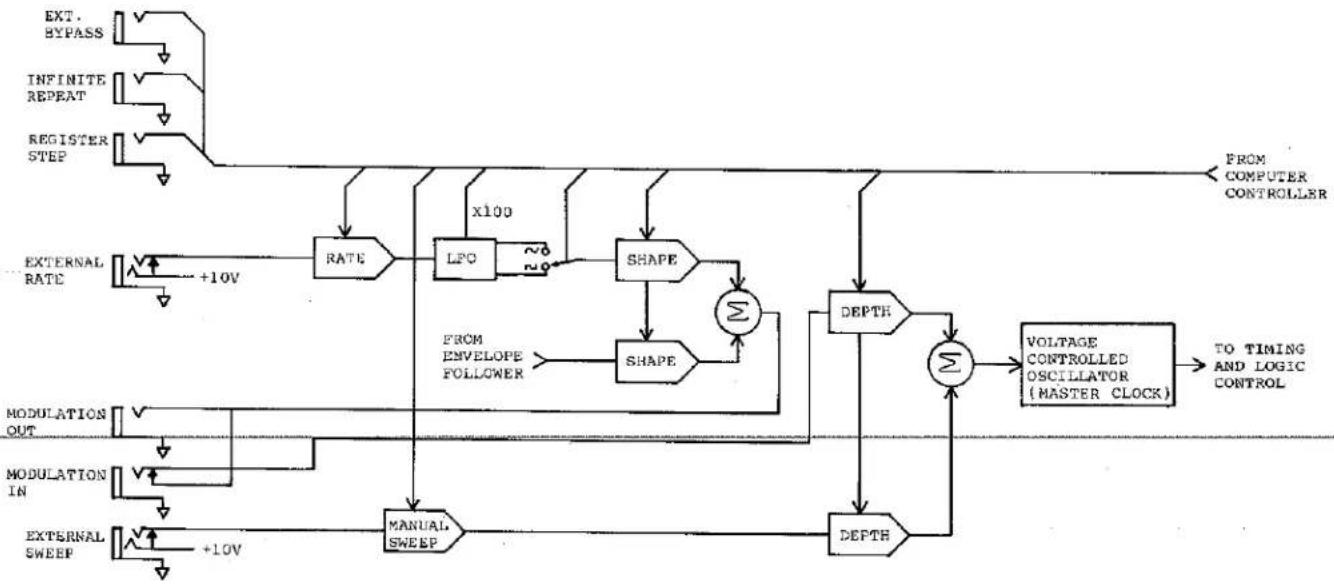
flowchart
graph TD
    A["EXT. BYPASS"] --> B["RATE"]
    C["INFINITE REPEAT"] --> D["LPO"]
    E["REGISTER STEP"] --> F["X100"]
    G["EXTERNAL RATE"] --> H["+10V"]
    I["MODULATION OUT"] --> J["MANUAL SWEEP"]
    K["MODULATION IN"] --> L["MANUAL SWEEP"]
    M["EXTERNAL SWEEP"] --> N["+10V"]
    O["FROM COMPUTER CONTROLLER"] --> P["DEPTH"]
    Q["VOLTAGE CONTROLLED OSCILLATOR (MASTER CLOCK)"] --> R["Σ"]
    S["TO TIMING AND LOGIC CONTROL"] --> T["DEPTH"]
    U["FROM ENVELOPE FOLLOWER"] --> V["SHAPE"]
    W["SHAPE"] --> X["Σ"]
    Y["ΔΣ"] --> Z["DEPTH"]
    AA["ΔΣ"] --> AB["DEPTH"]
    AC["ΔΣ"] --> AD["DEPTH"]
Figure 5-1 - Model 97 VCO Section Block Diagram
5.3 USING THE LFO
The LFO is an oscillator, primarily intended to operate at low frequencies (below 500 Hz) for the purpose of shifting the set delay time up and down. To explain the details of how the LFO affects the sound, we'll ask some questions.
How much does the LFO vary the delay time? You determine that with the DEPTH control. If DEPTH is set at "0" (full counterclockwise rotation), the LFO has no effect, whereas with DEPTH at "10" (full CW rotation), the delay deviation is maximum.
How fast does the delay time deviation occur? You determine that with the RATE control and its associated "X100" scaling button. Normally the X100 button is not pressed (the LED above it is Off), and the RATE is variable between 0.05 Hz and 5 Hz. Pressing the X100 button changes the available oscillation RATE to between 5 Hz and 500 Hz. Be aware that in high speed mode there can be audible sidebands caused by frequency modulation of the program.
What kind of delay variation occurs? You determine that with two controls: SHAPE and the sine/square button. SHAPE is a function unique to Lexicon; turning the control to "LFO" (fully CW rotation) causes the delay time to be modulated up and down by a sine wave or a square wave signal, as set by the associated sine/square button and indicated by a pair of LEDs above that button. The frequency or speed of the modulation is set with the RATE control.
The unique aspect of the Model 97's LFO modulation relates to the "ENV" or envelope position of the SHAPE control (full CCW rotation). When set at ENV position (envelope follower), the delay time will vary in a seemingly random fashion, actually dependent upon the input signal's amplitude. That is, loud peaks or transient attacks (such as drum beats) "push" the delay time up and down. With pure ENV modulation (SHAPE fully CCW), the RATE control has no effect.
The envelope follower provides a means to obtain automatic deviations in delay time while avoiding the sometimes boring regularity of a set VCO speed. Setting SHAPE in a mid position between "ENV" and "LFO" blends the sine or square wave modulation with additional "pushes" from the envelope follower (useful for many doubling and flanging effects).
At some settings, you will notice that the LFO definitely changes the pitch of the signal. At slow rates with sine wave modulation, the LFO can be used to create vibrato. Faster LFO modulation can induce secondary tones, causing effects similar to a ring modulator.
5.4 DYNAMIC RECIRCULATION (AND THE VCA BUTTON)
Pressing the VCA (voltage controlled amplifier) button turns On the LED above that button and places the Model 97 in "dynamic recirculation" mode. If you use a long delay, or, more accurately, if you use recirculation to "stretch" the effective decay time, then the presence of continuing input signals can often clutter the sound. A guitarist picking a complex passage, for example, can be distracted by a lot of recirculation. Yet, at the conclusion of that passage, it may be very desirable to have a long, gradual decay of the sound. The Model 97's unique dynamic recirculation feature makes this input-responsive decay possible.
When the VCA LED is On, the amount of recirculation you set with the A-FB and/or B-FB controls in the INPUT MIX section will exist only after the trailing edge of the input signal envelope -- that is, after the last note. In the middle of a passage, however, an envelope follower senses the input signal and feeds a control voltage to the VCA through which the recirculation signals are fed. This, in turn, reduces the amount of recirculation (and hence reduces the "clutter") while the input is active. After the last note, the envelope follower senses nothing so the VCA "opens up," and the set amount of recirculation is restored.
5.5 CROSS FADING BETWEEN EFFECTS (AND THE VCA BUTTON)
Like many buttons on the Model 97, the VCA button has a second function, depending upon how you use it. When you select various memory registers, either the factory preset bank or your own in banks A through D, the change between effects can be instantaneous. Sometimes the immediate changeover is desirable, yet at other times it is not. For example, part of the signal may be caught "mid process" in the delay line and, by virtue of the suddenly changed control settings, unusual artifacts can be produced. Perhaps there will be a pitch change that lingers on, or some other audible glitch. Even in the absence of audible artifacts, there are times when the sudden change between effects can, itself, be unpleasant.
The Model 97 is designed with the ability to gently cross fade between memorized effects. Essentially, the A-FB and B-FB sliders in the INPUT MIX section and the A and B DELAY sliders in the OUTPUT MIX section are brought to zero (internally) from their current settings and then brought up to the newly selected settings at a fixed rate. Necessarily, the cross fade causes a momentary "hole" in the program, but the dip in level is usually less objectionable than an audible glitch or artifact. Since the mix levels of current and next selected memories will vary, the actual cross fade time is not fixed; it may take a few milliseconds or a half second.
To select cross-fade mode:
-
Press VCA and hold it in.
-
Press REGISTER 1;
then release both buttons.
To select immediate mode:
-
Press VCA and hold it in.
-
Press REGISTER 2;
then release both buttons.
Whether the Model 97 is placed in cross-fade or in immediate mode, it remains in that mode even after power is turned Off. Therefore, we recommend you leave the unit in the mode used most often (whatever your preference) except when the other mode is specifically needed.
5.6 INFINITE REPEAT
It is possible to capture a short program segment and to repeat that segment indefinitely. The maximum length of the segment is equal to the maximum available delay time of the Model 97 (with whatever memory extension options may be installed). In order to initiate this infinite hold function:
- Press ∞ on the front panel to
start the repeat.
- Press again to restore
normal operation.
As an alternate to (1 and 2) above,
plug a momentary foot switch into the rear-panel to REPEAT jack, and actuate the switch to start and cancel the repeat. The first momentary remote switch closure will initiate the infinite repeat, and the second closure will restore normal Model 97 operation.
The signal held in memory is equal to the maximum delay time available at the time that INFINITE REPEAT is initiated. That is, the maximum delay available with a given memory option times the MANUAL SWEEP setting. The DELAY controls adjacent to the time display do not affect the length of the infinite repeat. They do, however, determine where in the memory cycle the repeat is initiated. The entire memory contents will repeat indefinitely, with the difference between the A and B DELAY settings determining the separation (in time) of the two outputs. If you want both the A and B outputs to be exactly synchronized, set them to either the maximum or minimum delay (the only points at which both can be set for the same time).
When the oo switch or foot switch is first actuated, the program to be repeated is already in memory. At first, it may be helpful for the performer to get a "feel" for how long the delay is so that the repeat can be actuated at the appropriate moment. To practice or obtain the feel prior to actually using infinite repeat, one can set the DELAY time at maximum, bring up some recirculation, and play the notes to be repeated. If the delay is then insufficient to accommodate the notes, increase MANUAL SWEEP; if there is a "gap," decrease MANUAL SWEEP.
5.7 USING A REMOTE SWITCH TO ADVANCE THROUGH THE MEMORY REGISTERS
By plugging a momentary contact foot switch into the rear panel REGISTER STEP jack, a performer can advance from one memory register to the next without having to press the Model 97 REGISTER or BANK SELECT buttons. Assuming all memories are used, each time the remote switch contacts touch, the Model 97 will advance to the next memory; after it reaches REGISTER #8, it will advance to the next MEMORY BANK. (Switch design is discussed in Section 3.)
It is possible, however, to restrict the automatic register step function to any group of registers within a given memory bank. Simply clear the register that comes after the last register you want to use (see Section 4 for clearing instructions). Then the remote switch will cause the Model 97 to step through all the registers up to the blank, return to the #1 register, and continue the loop.
To provide a further degree of control, you can store a blank register just before the first memory you wish to access with the REGISTER STEP function. For example storing a blank at #3 and at #7 will allow you to repeatedly step through #4, #5 and #6. However, you must first manually press one of the register buttons in that "window" (e.g., #4, #5 or #6 in this example).
For different songs, etc., you can set up several groups of memories bordered by cleared (blank) registers in the four banks. (You can step through the end of one bank and into the next, but the unit will return only as far as the beginning of the bank in which it finds the first cleared register.) Just manually select the particular bank and register you wish to access first for a given song, and use the foot switch from there.
During a busy mixing session, an engineer may prefer to use the remote REGISTER STEP switching feature rather than to physically reach over and operate the Model 97. A foot switch need not be used here – any similar momentary contact type switch is useable. If the application comes up regularly, consider mounting a switch in the mixing console.
5.8 USING RECORDED CUES TO ADVANCE THROUGH THE MEMORY REGISTERS
A form of quasi-automation is possible, using tape recorded cue tones to automatically step through the memory registers. The same bracketing techniques described in the foot switch discussion in Section 5.8 also apply here (i.e., clearing the register after the last one you wish to access, and optionally, the one before the first register). The cue tones are output from the Model 97's TAPE STORE OUT jack when stepping through the registers, but only after following the special button pressing sequence described below.
NOTE: It is assumed the Model 97 TAPE STORE OUT jack is connected to a tape recorder line input, and that the track is in record mode. Generally this will be done in sync with a multi-track tape so that effects changes occur synchronously with audio program recorded on that tape.
To prepare the Model 97 to work with step cue tones:
- Press TAPE and hold it in.
- Press MAN ; then release both.
All displays now flicker to indicate the machine is in tape cue mode. The Model 97 is now ready to be switched from one register to the next in a special way that simulatneously applies a special cue tone at the TAPE STORE OUT jack. You will perform this special register stepping while listening to the program on other tracks of the same tape (or on a tape which is sync-locked to the tape on which the cue tones are being recorded.
- Now press TAPE once each
time you wish to step to the next register.
- To escape this mode, press
escape this mode if you are going to play back the tape immediately).
To have the Model 97 automatically step through the memories upon play-back of a cue tone coded tape, prepared as above, plug the track's line output into the Model 97 TAPE STORE
IN jack. If the Model 97 is no longer in cue tone mode, again follow the pre-ceeding Steps 1 and 2 (these steps also prepare the unit to read the tape cues). Each time a cue tone appears at the Model 97 TAPE STORE IN jack, the unit will step to the next memory register. Remember, though, that initially the unit must be manually placed in the first memory you wish to use so that the cue tones advance the unit through the proper registers.
5.9 REMOTE BYPASSING SWITCHING
The rear panel BYPASS jack can be connected to a foot switch or other remote switch. When the switch contacts are momentarily closed, the Model 97 will be bypassed, just as though the front panel BYP button were pressed; in fact, the LED above the front panel BYP button will be On. When the remote switch contacts are closed again, the Model 97 will again process the signal and the BYP LED will turn Off. (Switch design is covered in Section 3.)
5.10 REMOTE CONTROL OF THE LFO RATE OR THE VCO MANUAL SWEEP
It is possible to remotely duplicate the functions of the front panel RATE and MANUAL SWEEP controls (see Figure 5-1). A zero through 10 V DC signal applied to the rear panel RATE IN jack will sweep the rate through the full 100:1 range available on the front panel (providing the front panel RATE control is set fully clockwise). Similarly, a zero through 10 V signal applied to the EXTERNAL DELAY SWEEP jack will sweep the delay through the full 3:1 range available on the front panel (providing the DEPTH control is set at "0" and the MANUAL SWEEP control is set at "X0.5").
The connections for the EXTERNAL DELAY SWEEP and RATE IN jacks are covered in Section 3. Additional applications information can be found in Section 6. We do wish to emphasize here that the range of control available with these remote controls will depend upon the setting of related front panel controls. In the case of DELAY SWEEP, 0 volts will give the lowest clock frequency (the longest delay time). For RATE, 0 volts will give the lowest frequency (the slowest sweep).
5.11 REMOTE CONTROL (OR LINKAGE) OF THE LFO's MODULATION
The modulation of the LFO refers to the waveform output by the SHAPE control - from a sine or square wave LFO component (low frequency oscillator) to the ENV (input ENVelope follower). It is possible to use an external source of 0 to +10 V to replace the front panel SHAPE control function. Simply plug that source into the rear panel MODULATION IN jack. It may be a control voltage from a synthesizer or sequencer, or the audio output of an oscillator or electronic musical instrument (in which case a positive DC offset may be added to keep the voltage positive).
The Model 97 also has a MODULATION OUT jack; it may be patched to the MODULATION IN jack of another Model 97. This allows two channels of audio to be processed discretely, yet with synchronous modulation which is keyed by one of the units. The connections to these jacks are covered in Section 3, and further applications in Section 6.
6.1 WHERE TO USE THE MODEL 97 — BASIC SETUPS
Within a given sound system, there are a number of different locations where the Model 97 can be inserted. The examples shown below are representative of typical live performance and studio setups. Front panel settings to achieve a few exemplary effects are given in subsequent pages of this section, but we have not tried to be comprehensive. That's because you can quickly derive the front panel settings for the 8 factory preset effects (or any effects you may have "read" from a tape recorded by another Model 97 user); remember to just set each knob at its "null" position where the DELAY display momentarily blinks, as described in Section 4.4.
In general, when using the Model 97 MAIN INPUT, it is a good idea to initially set its GAIN switch to "0 dB" position. Then, if the input level is too low to light up the headroom display at "18" or "24" with the MAIN SOURCE slider of the INPUT section all the way up, press in the GAIN switch to "+20 dB" position.
If an electric guitar is plugged directly into the Model 97, the GAIN switch will have to be set to "+20 dB" (unless the guitar has a built-in battery-powered preamplifier, as a few do). The amp's "guitar input" could then be fed from the Model 97 MASTER OUT jack; a 20 dB to 40 dB pad will probably be required at the guitar amp input to prevent clipping by attenuating the Model 97's line level output.

flowchart
graph TD
    A["INPUT SOURCE (electric guitar)"] --> B["PREAM OUTPUT"]
    A --> C["INPUT JACK"]
    B --> D["MAIN AMP INPUT"]
    C --> D
    D --> E["Speaker OUTPUT (OR BUILT IN SPEAKER)"]
    E --> F["OUT"]
    F --> G["FAIR SWITCHES"]
    G --> H["FOOT PEDALS"]
    H --> I["FOOT SWITCHES"]
    I --> J["FOOT SWITCHES"]
    J --> K["FAIR SWITCHES"]
    K --> L["OUT"]
    L --> M["FAIR SWITCHES"]
    M --> N["FOOT SWITCHES"]
    N --> O["FAIR SWITCHES"]
    O --> P["OUT"]
    P --> Q["FAIR SWITCHES"]
    Q --> R["FOOT SWITCHES"]
    R --> S["FAIR SWITCHES"]
    S --> T["OUT"]
    T --> U["FAIR SWITCHES"]
    U --> V["FOOT SWITCHES"]
    V --> W["FAIR SWITCHES"]
    W --> X["OUT"]
    X --> Y["FAIR SWITCHES"]
    Y --> Z["FOOT SWITCHES"]
    Z --> AA["FAIR SWITCHES"]
    AA --> AB["OUT"]
    AB --> AC["FAIR SWITCHES"]
    AC --> AD["FOOT SWITCHES"]
    AD --> AE["FAIR SWITCHES"]
    AE --> AF["OUT"]
    AF --> AG["FAIR SWITCHES"]
    AG --> AH["FOOT SWITCHES"]
Figure 6-1 - Basic Setup for an Electric Guitar Player
Note: Optional foot pedals are shown for sweeping the delay time and controlling the LFO rate. Optional foot switches are shown for bypass, infinite repeat and register step functions.
This setup processes a single signal to feed a single channel of amplification (See Figure 6-3 for creating a pseudo-stereo feed from one or two mono signals.) When using several keyboards and mixing them locally, the Model 97 can be connected in the echo send/return loop of the mixing board as shown in Figure 6-4.
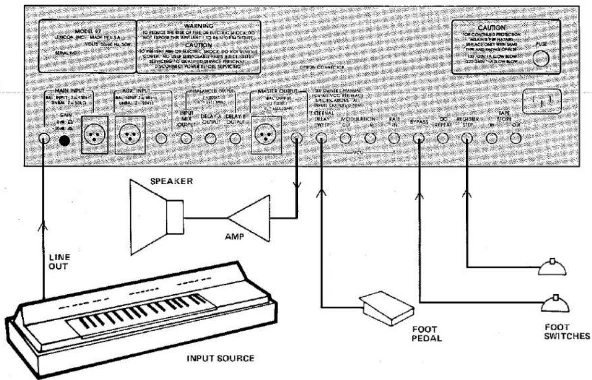
flowchart
graph TD
    A["INPUT SOURCE"] --> B["Speaker"]
    A --> C["AMP"]
    A --> D["MAIN INPUT"]
    A --> E["MAIN INPUT 1-2-10bit/10bit 2-3-8bit"]
    A --> F["AUX INPUT"]
    A --> G["MAIN INPUT 2-3-8bit/10bit 2-7-6bit"]
    A --> H["MAIN INPUT 3-4-5bit/10bit 3-6-4bit"]
    A --> I["MAIN INPUT 4-5-6bit/10bit 4-5-5bit"]
    A --> J["AUX INPUT 5-6-6bit/10bit 5-7-6bit"]
    A --> K["MAIN INPUT 6-7-7bit/10bit 7-8-7bit"]
    A --> L["MAIN INPUT 7-8-8bit/10bit 8-9-8bit"]
    A --> M["AUX INPUT 8-9-9bit/10bit 9-10-10bit"]
    A --> N["AUX INPUT 9-10-10bit/10bit 10-11-11bit"]
    A --> O["AUX INPUT 10-11-11bit/10bit 11-12-12bit"]
    A --> P["AUX INPUT 11-12-12bit/10bit 12-13-13bit"]
    A --> Q["AUX INPUT 12-13-13bit/10bit 13-14-14bit"]
    A --> R["AUX INPUT 13-14-14bit/10bit 14-15-15bit"]
    A --> S["AUX INPUT 14-15-15bit/10bit 15-16-16bit"]
    A --> T["AUX INPUT 15-16-16bit/10bit 16-17-17bit"]
    A --> U["AUX INPUT 16-17-17bit/10bit 17-18-18bit"]
    A --> V["AUX INPUT 17-18-18bit/10bit 18-19-19bit"]
    A --> W["AUX INPUT 18-19-19bit/10bit 19-20-21bit"]
    A --> X["AUX INPUT 20-21-22bit/10bit 22-23-24bit"]
    A --> Y["AUX INPUT 22-23-24bit/10bit 23-24-25bit"]
    A --> Z["AUX INPUT 24-25-26bit/10bit 26-27-28bit"]
    A --> AA["AUX INPUT 26-27-28bit/10bit 28-29-30bit"]
    A --> AB["AUX INPUT 30+ - - - - - - - - - - - - - - - - - - - - - - - - - - - - - - - - - - - - - - - - - - - - - - - - - - - - - - - - - - - - - - - - - - - - - - - - - - - - - - - - - - - - - - - - - - - - - - - - - - - - -<br>    A --> AC[FOOT PEDAL"]
    A --> AD["FOOT SWITCHES"]
    AE["CAUTION"] --> AF["FOR CONTINUED PROTECTION ALABIND PER HAZARD INTRACTION WITH MAX FOR ENDING ON OFF"]
    AE --> AG["FOR ENDING ON OFF"]
    AE --> AH["FOR ENDING ON OFF"]
    AE --> AI["FOR ENDING ON OFF"]
    AE --> AJ["FOR ENDING ON OFF"]
    AE --> AK["FOR ENDING ON OFF"]
    AE --> AL["FOR ENDING ON OFF"]
    AE --> AM["FOR ENDING ON OFF"]
    AE --> AN["FOR ENDING ON OFF"]
    AE --> AO["FOR ENDING ON OFF"]
    AE --> AP["FOR ENDING ON OFF"]
    AE --> AQ["FOR ENDING ON OFF"]
    AE --> AR["FOR ENDING ON OFF"]
Figure 6-2 - Basic Mono Setup for Electronic Keyboard Player
Note: An optional foot pedal is shown for sweeping the delay time. Optional foot switches are shown for the bypass and register step functions.
This setup processes two different keyboards, mixing them together with the MAIN SOURCE and AUX SOURCE controls in the Model 97 INPUT MIX section. (The second keyboard, shown connected to the AUX INPUT, is optional.) A pseudo-stereo effect is obtained by feeding the "straight" (non-delayed) signal from the INPUT MIX OUT jack to one amplifier and speaker, and feeding a delayed signal from the MASTER OUT jack to the other amplifier and speaker. A stereo effect is obtained by using a moderate delay time (about 25 milliseconds) from one tap (A, for example), and perhaps a small amount of envelope modulation for "interest".

flowchart
graph TD
    A["INPUT SOURCES"] --> B["SO Box"]
    B --> C["Speaker"]
    C --> D["LEFT AMP"]
    D --> E["CAPC"]
    E --> F["CAUTION"]
    F --> G["FOOT SWITCHES"]
    G --> H["Ground"]
    style A fill:#f9f,stroke:#333
    style B fill:#ccf,stroke:#333
    style C fill:#cfc,stroke:#333
    style D fill:#fcc,stroke:#333
    style E fill:#cff,stroke:#333
    style F fill:#ffc,stroke:#333
    style G fill:#cfc,stroke:#333
    style H fill:#fcc,stroke:#333
Figure 6-3 - Pseudo Stereo Setup for Electronic Keyboard Player
Note: Optional root switches are shown for the bypass, infinite repeat and register step functions. The second instrument connected to the AUX INPUT is optional.

flowchart
graph TD
    A["Console Mic/Line Inputs"] --> B["AUDIO MIXING CONSOLE"]
    C["Microphones, ELECTRIC INSTRUMENTS, ETC."] --> B
    D["Main Input"] --> B
    E["Main Input"] --> F["AUX INPUT"]
    G["Main Input"] --> H["INPUT MIX OUTPUT"]
    I["Main Input"] --> J["DELAY A OUTPUT"]
    K["Main Input"] --> L["DELAY B OUTPUT"]
    M["Main Input"] --> N["MASTR OUTPUT"]
    O["Main Input"] --> P["OUTPUT"]
    Q["Main Input"] --> R["OUTPUT"]
    S["Main Input"] --> T["OUTPUT"]
    U["Main Input"] --> V["OUTPUT"]
    W["Main Input"] --> X["OUTPUT"]
    Y["Main Input"] --> Z["OUTPUT"]
    AA["Main Input"] --> AB["OUTPUT"]
    AC["Main Input"] --> AD["OUTPUT"]
    AE["Main Input"] --> AF["OUTPUT"]
    AG["Main Input"] --> AH["OUTPUT"]
    AI["Main Input"] --> AJ["OUTPUT"]
    AK["Main Input"] --> AL["OUTPUT"]
    AM["Main Input"] --> AN["OUTPUT"]
    AO["Main Input"] --> AP["OUTPUT"]
    AQ["Main Input"] --> AR["OUTPUT"]
    AS["Main Input"] --> AT["OUTPUT"]
    AU["Main Input"] --> AV["OUTPUT"]
    AW["Main Input"] --> AX["OUTPUT"]
    AY["Main Input"] --> AZ["AUX INPUT"]
    BA["Main Input"] --> BB["AUX INPUT"]
    BC["Main Input"] --> BD["AUX INPUT"]
    BE["Main Input"] --> BF["AUX INPUT"]
    BG["Main Input"] --> BH["AUX INPUT"]
    BI["Main Input"] --> BJ["AUX INPUT"]
    BK["Main Input"] --> BL["AUX INPUT"]
    BM["Main Input"] --> BN["AUX INPUT"]
    BO["Main Input"] --> BP["AUX INPUT"]
    BQ["Main Input"] --> BR["AUX INPUT"]
    BS["Main Input"] --> BT["AUX INPUT"]
    BU["Main Input"] --> BV["AUX INPUT"]
    BW["Main Input"] --> BX["AUX INPUT"]
    BY["Main Input"] --> BZ["AUX INPUT"]
    CA["Main Input"] --> CB["AUX INPUT"]
    CC["Main Input"] --> CD["AUX INPUT"]
    CE["Main Input"] --> CF["AUX INPUT"]
    GD["Main Input"] --> DH["AUX INPUT"]
    DI["Main Input"] --> DJ["AUX INPUT"]
    DK["Main Input"] --> DL["AUX INPUT"]
    DV["Main Input"] --> DW["AUX INPUT"]
    DX["Main Input"] --> DXA["AUX INPUT"]
    DXB["Main Input"] --> DXC["AUX INPUT"]
    DXC --> DXD["AUX INPUT"]
    DXD --> DXE["AUX INPUT"]
    DXE --> DXF["AUX INPUT"]
    DXF --> DXG["AUX INPUT"]
    DXG --> DXH["AUX INPUT"]
    DXH --> DXI["AUX INPUT"]
    DXI --> DXJ["AUX INPUT"]
    DXJ --> DXK["AUX INPUT"]
    DXK --> DXL["AUX INPUT"]
    DXL --> DXM["AUX INPUT"]
    DXM --> DXN["AUX INPUT"]
    DXN --> DXO["AUX INPUT"]
    DXO --> DXP["AUX INPUT"]
    DXP --> DXQ["AUX INPUT"]
    DXQ --> DXR["AUX INPUT"]
    DXR --> DXS["AUX INPUT"]
    DXS --> DXT["AUX INPUT"]

    subgraph Audio Mixing Console
        B
        C
        D
        E
        F
        G
        H
        I
        J
        K
        L
        M
        N
        O
        P
        Q
        R
        S
        T
        U
        V
        W
        X
        Y
        Z
        AA
        AB
        AC
        AD
        AE
        AF
        AG
        AH
        AI
        AJ
        AK
        AL
        AM
        AN
        AO
        AP
        AQ
        AR
        AS
        AT
        AU
        AV
        AW
        AX
        AY
        AZ
        BA
        BB
        BC
        BD
        BE
        BF
        BG
        BH
        BI
        BJ
        BK
        BL
        BM
        BN
        BO
        BP
        BP1
        BP2
        BP3
        BP4
        BP5
        BP6
        BP7
        BP8
        BP9
        BP10
        BP11
        BP12
        BP13
        BP14
        BP15
        BP16
        BP17
        BP18
        BP19
        BP20
        BP21
        BP22
        BP23
        BP24
        BP25
        BP26
        BP27
        BP28
        BP29
        BP30
        BP31
        BP32
        BP33
        BP34
        BP35
        BP36
        BP37
        BP38
        BP39
        BP40
        BP41
        BP42
        BP43
        BP44
        BP45
        BP46
        BP47
        BP48
        BP49
        BP50
        BP51
        BP52
        BP53
        BP54
        BP55
        BP56
        BP57
        BP58
        BP59
        BP60
        BP61
        BP62
        BP63
        BP64
        BP65
        BP66
        BP67
        BP68
        BP69
        BP70
        BP71
        BP72
        BP73
        BP74
        BP75
        BP76
        BP77
        BP78
        BP79
        BP80
        BP81
        BP82
        BP83
        BP84
        BP85
        BP86
        BP87
        BP88
        BP89
        BP90
        BP91
        BP92
        BP93
        BP94
        BP95
        BP96
        BP97
        BP98
        BP99
    end

    subgraph Audio Mixing Console (Reinforcement)
      ABAmpAmpAmpAmpAmpAmpAmpAmpAmpAmpAmpAmpAmpAmpAmpAmpAmpAmpAmpAmpAmpAmpAmpAmpAmpAmpAmpAmpAmpAmpAmpAmpAmpAmpAmpAmpAmpAmpAmpAmpAmpAmpAmpAmpAmpAmpAmpAmpAmpAmpAmpCPEAKERSAMPAmpAmpAmpAmpAmpAmpAmpAmpAmpAmpAmpAmpAmpAmpAmpAmpAmpAmpAmpAmpAmpAmpAmpAmpAmpAmpAmpAmpAmpAmpAmpAmpAmpAmpAmpCPEAKERSAMPAmpAmpAmpAmpAmpAmpAmpAmpAmpAmpAmpCPEAKERSAMPAmpAmpAmpAmpAmpAmpCPEAKERSAMPaMPaMPaMPaMPaMPaMPaMPaMPaMPaMPaMPaMPaMPaMPaMPaMPaMPaMPaMPaMPaMPaMPaMPaMPaMPaMPaMPaMPaMPaMPaMPaMPaMPaMPaMPaMPaMPaMPaMPaMPaMPaMPaMPaMPaMPaMPaMPaMPaMPaMPaMPIeAMPaMPaMPaMPaMPaMPaMPaMPaMPaMPaMPaMPaMPaMPaMPaMPaMPaMPaMPaMPaMPaMPaMPaMPaMPaMPaMPaMPaMPaMPaMPaMPaMPaMPaMPaMPaMPaMPaMPaMPaMPaMPaMPaMPaMPaMPaMPaMPaMPaMPamuMPIeAMPaMPaMPaMPaMPaMPaMPaMPaMPaMPaMPaMPaMPamuMPIeAMPaMPaMPaMPaMPaMPaMPamuMPIeAMPamuMPIeAMPamuMPIeAMPamuMPIeAMPamuMPIeAMPamuMPIeAMPamuMPIeAMPamuMPIeAMPamuMPIeAMPamuMPIeAMPamuMPIeAMPamuMPIeAMPamuMPIeAMPamuMPIeAMPamuMPIeAMPamuMPIeAMPamuMPIeAMPamuMPIeAMPamuMPIeAMPamuMPIeAMPamuMPIeAMoMPIeAMPamuMPIeAMPamuMPIeAMPamuMPIeAMPamuMPIeAMPamuMPIeAMPamuMPIeAMPamuMPIeAMPamuMPIeAMPamuMPIeAMPamuMPIeAMPamuMPIeAMPamuMPIeAMPamuMPIeAMPamuMPIeAMPamuMPIeAMPamuMPIeAMPamuMPIeAMPamuMPIeAMPamuMPIeAMPamcAMPamuMPIeAMPamuMPIeAMPamuMPIeAMPamuMPIeAMPamuMPIeAMPamuMPIeAMPamuMPIeAMPamuMPIeAMPamuMPIeAMPamuMPIeAMPamuMPIeAMPamuMPIeAMPamuMPIeAMPamuMPIeAMPamuMPIeAMPamuMPIeAMPamuMPIeAMPamuMPIeAMPamuMPIeAMPamuMPIeiAMPamuMPIeAMPamuMPIeAMPamuMPIeAMPamuMPIeAMPamuMPIeAMPamuMPIeAMPamuMPIeAMPamuMPIeAMPamuMPIeAMPamuMPIeAMPamuMPIeAMPamuMPIeAMPamuMPIeAMPamuMPIeAMPamuMPIeAMPumoMnSPIoMnSPIoMnSPIoMnSPIoMnSPIoMnSPIoMnSPIoMnSPIoMnSPIoMnSPIoMnSPIoMnSPIoMnSPIoMnSPIoMnSPIoMnSPIoMnSPIoMnSPIoMnSPIoMnSPIoMnSPIoMnSPIoMnSPIoMnSPIoMnSPIoMn SPIoMnSPIoMn SPIoMnSPIoMn SPIoMnSPIoMn SPIoMnSPIoMn SPIoMnSPIoMn SPIoMnSPIoMn SPIoMnSPIoMn SPIoMnSPIoMn SPIoMnSPIoMn SPIoMnSPIoMn SPIoMnSPIoMn SPIoMnSPIoMn SPIoMn SPIoMn SPIoMn SPIoMn SPIoMn SPIoMn SPIoMn SPIoMn SPIoMn SPIoMn SPIoMn SPIoMn SPIoMn SPIoMn SPIoMn SPIoMn SPIoMn SPIoMn SPIoMn SPIoMn SPIoMn SPIoMn SPIoMn SPIoMn SPIoMnPIoMnPIoMnPIoMnPIoMnPIoMnPIoMnPIoMnPIoMnPIoMnPIoMnPIoMnPIoMnPIoMnPIoMnPIoMnPIoMnPIoMnPIoMnPIoMnPIoMnPIoMnPIoMnPIoMnPIoMnPIoMnUIPOUOUIOUIOUIOUIOUIOUIOUIOUIOUIOUIOUIOUIOUIOUIOUIOUIOUIOUIOUIOUIOUIOUIOUIOUIOUIOUIOUIOUIOUIOUIOUIOUIOUIOUIOUIOUIOUIOUIOUIOUIOUIOUIOUIOUIOUIOUIOUIOUIOUIOUIOIIPOUOIOIOIOIOIOIOIOIOIOIOIOIOIOIOIOIOIOIOIOIOIOIOIOIOIOIOIOIOIOIOIOIOIOIOIOIOIOIOIOIOIOIOIOIOIOIOIOIOIOIOIOIOIOIOIOIOIOIOIOIOIOIOIOIOIOIOIOIOIOIOIOIOIOIOIOIOIOIOIOIOIOIOIOIOIOIOIOIOIOIOIOIOIOIOIOIOIOIOIOIOioIPOUOIOIOIOIOIOIOIOIOIOIOIOIOIOIOIOIOIOIOIOIOIOIOIOIOIOIOioIPOUOIOioIPOUOioioioioioioioioioioioioioioioioioioioioioioioioioioioioioioioioioioioioioioioioioioioioioioioioioioioioioioioioioioioioioioioioioioioioioioioioioioioioioioioioioioioioioioioioioioioioioioioioie o u u u u u u u u u u u u u u u u u u u u u u u u u u u u u u u u u u u u u u u u u u u u u u u u u u u u u u u u u u u u u u u u u u u u u u u u u u u u u u u u u u u u u u u u u u u u u u u u u u u u U U U U U U U U U U U U U U U U U U U U U U U U U U U U U U U U U U U U U U U U U U U U U U U U U U U U U U U U U U U U U U U U U U U U U U U U U U U U U U U U U U U U U U U U U U U U U U U U U U U U V O O O O O O O O O O O O O O O O O O O O O O O O O O O O O O O O O O O O O O O O O O O O O O O O O O O O O O O O O O O O O O O O O O O O O O O O O O O O O O O O O O O O O O O O O O O O O O O O O O O O S P E A P A P A P A P A P A P A P A P A P A P A P A P A P A P A P A P A P A P A P A P A P A P A P A P A P A P A P A P A P A P A P A P A P A P A P A P A P A P A P A P A P A P A P A P A P A P A P A P A P A P A F S E T S E T S E T S E T S E T S E T S E T S E T S E T S E T S E T S E T S E T S E T S E T S E T S E T S E T S E T S E T S E T S E T S E T S E T S E T S E T S E T S E T S E T S E T S E T S E T S E T S E T sE T sE T sE T sE T sE T sE T sE T sE T sE T sE T sE T sE T sE T sE T sE T sE T sE T sE T sE T sE T sE T sE T sE T sE T sE T sE T sE T sE T sE T sE T sE T sE T sE T sE tS E T sE tS E T sE tS E T sE tS E T sE tS E T sE tS E T sE tS E T sE tS E T sE tS E T sE tS E T sE tS E T sE tS E T sE tS E T sE tS E T sE tS E T sE tS E T sE tS E T sE eT eT eT eT eT eT eT eT eT eT eT eT eT eT eT eT eT eT eT eT eT eT eT eT eT eT eT eT eT eT eT eT eT eT eT eT eT eT eT eT eT eT eT eT eT eT eT eT eT eT eS E T sE tS E T sE tS E T sE tS E T sE tS E T sE tS E T sE tS E T sE tS E T sE tS E T sE tS E T sE tS E T sE tS E T sE tS E tS E tS E tS E tS E tS E tS E tS E tS E tS E tS E tS E tS E tS E tS E tS E tS E tS E tS E tS E tS E tS E tS E tS E tS E tS E tS E tS E tS E tS E tS E tS E tS E tS E rWt a b b c d d d d d d d d d d d d d d d d d d d d d d d d d d d d d d d d d d d d d d d d d d d d d d d d d d d d d d d d d d d d d d d d d d d d d d d d d d d d d d d d d d d d d d d d d d d d d d d d d d d d D l o o o o o o o o o o o o o o o o o o o o o o o o o o o o o o o o o o o o o o o o o o o o o o o o o o o o o o o o o o o o o o o o o o o o o o o o o o o o o o o o o o o o o o o o o o o o o o o i n a p a m a m a m a m a m a m a m a m a m a m a m a m a m a m a m a m a m a m a m a m a m a m a m a m a m a m a m a m a m a m a m a m a m a m a m a m a m a m a m a m a m a m a m a m a m a m a m a m a m a m am a m a m a m a m a m a m a m a m a m a m a m a m a m a m a m a m a m a m a m a m a m a m a m a m a m a m a m a m a m a m a m a m a m a m a m a m a m a m a m a m a m a m a m a m a m a m a m a m a m a f l l l l l l l l l l l l l l l l l l l l l l l l l l l l l l l l l l l l l l l l l l l l l l l l l l l l l l l l l l l l l l l l l l l l l l l l l l l l l l l l l l l l l l l l l l l l l l l l l l l l |
    subgraph Audio Mixing Console (Audio Mixing Console) |
|
|
|
|
|
|
|
|
|
|
|
|
|
|
|
|
|
|
|
|
|
|
|
|
|
|
|
|
|
|
|
|
|
|
|
|
|
|
|
|
|
|
|
|
|
|
|
|
|
|
| |
| Console Mic/Line Inputs |
| Microphones, Electric Instruments, etc. |
| Echo/Effects Return |
| From Console Main Output (Reinforcement) or Monitor Output (Recording) |
| Audio Mixing Console (Audio Mixing Console) |
| From Console Bus Output (For Recording) |
| From Console Tape Machine (2-TRACK Tape Machine) |
Figure 6-4 - Basic Connection to a Recording or Sound Reinforcement Mixing Console
This setup is viable in the recording studio or in a live or recorded sound reinforcement situation. The mixing console's echo or effect send (output) is connected to the MAIN INPUT. Processed signal from the MASTER OUTPUT is connected to the console's echo or effect return (input). In this type of installation, the Model 97's MAIN SOURCE control in the OUTPUT MIX section usually will be all the way down, since input source signals can be blended with the delayed program back at the mixing console. However, there are some effects that benefit from MAIN SOURCE mixing at the Model 97 — for instance phasing, which relies upon a "comb filter" created when the delayed and direct signals are mixed together (and at nearly the same level). In such instances, if mixing of the delayed and direct signals were done at the console, then the actual effect would change as the return level were adjusted, not just the amount of effect.
6.2 GENERAL APPLICATIONS FOR DELAY LINES
Before considering the details of how to create specific delay processing effects, it will be useful to review what each effect is, and to thus establish a set of definitions. For readers who would like to learn more about time delay applications than is presented here, Application Note AN-3 is available from Lexicon. Contact us if you would like a copy. If you are already completely familiar with the effects, specific applications and setups are discussed in the balance of Section 6.
6.2.1 Flanging (Preset BANK, REGISTER #1)
Originally, flanging effects were created by recording the same program on two tape recorders, and playing both back in synchronization while mixing the identical program together. By slowing down one machine slightly, then the other, different phase cancellations would occur (this was done
by using hand pressure against the flange of the tape reels, hence the origin of the "reel flanging", or "flanging" for short). The result was a series of changing phase cancellations and reinforcements, producing a "comb filter" and the characteristic swishing, tunneling and fading sound.
Flanging with a delay line is much simpler: two tape machines need not be kept in relative sync. In fact, no tape machine is necessary — flanging can be done as a live effect. A short delay is mixed with the original signal, causing cancellation (nulling) at a frequency whose period (the time for one cycle) corresponds to twice the delay time. Cancellation also occurs on odd harmonics of that frequency. The depth of cancellation depends on the level balance of direct and delayed sounds (when the SOURCE and DELAY controls in the OUTPUT MIX section are set at the same level, the deepest cancellation, and hence the maximum effect, occurs.
The classic sweeping flange occurs when the delay time is continuously
varied, causing the null frequencies to sweep. As these nulls (notches in response) sweep across the various components of the program input, different harmonics and fundamentals are boosted or cut in relation to each other; the tone of the input is thus caused to constantly change.
Since flanging relies on precise phase cancellations, it must be done electrically, either by mixing the input and delayed signal, or two delayed signals with each other (see Section 6.5). It cannot be achieved acoustically in stereo.
A further variation occurs if the polarity of the delayed signal is inverted with respect to the input signal (using the INV button and the #4 or #5 REGISTER buttons). Since this is similar to a 180° phase shift, the comb filter pattern is shifted. The effect is known as "negative flange."
6.2.2 Resonant Flanging (Preset BANK, REGISTER #2)
The flanging effect can be further altered by recirculating the delay with the appropriate A-FB or B-FB controls. Larger amounts of recirculation cause exaggerated "deep" resonant flanges (do not confuse this with use of the DEPTH control, which only causes a wider sweep of the nulls, but no greater depth). Inverting the polarity of the feedback (with the INV button and the #1 or #2 REGISTER buttons) gives a "hollow" characteristic to the sound.
Use of the LFO's envelope (ENV position on the SHAPE control) produces an interesting "talking flange"; sweep is produced for each attack of the input. ENV and sine wave can be mixed for a complex sweep which is really quite pleasing. Square wave modulation, while unnatural, may be useful to create an unusual effect.
6.2.3 Doubling (Double Tracking) (Preset BANK, REGISTER #3)
Doubling, also called automatic double tracking or chorusing, combines original and delayed sound in order to make a single performer sound like two or more. True doubling is done by having a performer overdub a performance on a different track of a multi-track recorder; while the two or more "takes" are synchronized, normal pitch and timing variations between the supposedly identical performances provide enhancement. Whether the doubling is actual, or done by the Model 97 from a single take, the effect is to "thicken" vocal tracks. Of course, time delay can provide doubling during a live performance — something not practical with tape recorded effects.
Doubling provides the most convincing effect in stereo mode (using the MASTER and INPUT MIX outputs to feed different tape tracks or amplifier/speaker systems). If the effect is attempted in mono, the amount of delayed sound should not exceed the amount of direct sound in the output mix; i.e., the active DELAY control (A or B) in the OUTPUT MIX section should be no higher than the active SOURCE control (MAIN or AUX). Delay times in the 10 mS to 60 mS range are useful. A small amount of LFO modulation improves the effect.
6.2.4 Trebling (Triple Tracking) (Preset BANK, REGISTER #4)
Trebling, or triple tracking, is very similar to doubling, except that two different delays are mixed with the direct sound to make a single performer sound like three. The same notes apply as in the doubling discussion, and, in fact, the major difference is that both the A and B DELAY taps are used, and each should be set to a different delay time.
6.2.5 Long Delay Effects (Preset BANK, REGISTER #5)
When the delay time is equal to or greater than the time for a single beat of the music, it becomes possible to play counter points and harmonies against previously performed phrases. Careful synchronization of the performance and the delay time allows "polyphonic" sound from a single melodic line.
When FEEDBACK is used at long delay times, each sound entered at the input will repeat more than once before it fades out. Very full chords and textures can thus be built up; the chords will fade at a rate which depends on the DELAY TIME and the amount of FEEDBACK; 30 seconds or longer is possible. When the input has few harsh attacks, as with a bowed violin or a choral singing, the long delay, perhaps with some LFO modulation, will tend to multiply the number of instruments or voices heard.
6.2.6 Echo (Preset BANK, REGISTERS #6 & #7)
True echo occurs when the direct sound from a source bounces off an acoustically hard surface and returns so that it is heard as a distinct repetition of the original sound. The level of delayed sound relative to direct sound in the Model 97 OUTPUT MIX section gives audible cues as to the hardness of the reflecting surface(s). The initial delay time gives audible clues as to the relative distance between the sound source, the imaginary reflecting surface, and the listening position. Delay times of 60 mS to 150 mS create what is commonly known as "slap echo." Still longer delay times provide a very distinct repetition of the source, or "moderate echo." If both the A and B DELAY taps are used, there can be a double slap or a twice repeated moderate echo.
6.2.7 Echo with Recirculation (Preset BANK, REGISTER #8)
Recirculation of the delayed sound (feedback) provides multiple repetitions, and suggests two or more reflective surfaces that are bouncing the sound back and forth. In true "reverberation," there are random reflections, a gradual decay of overall level, and a gradual narrowing of bandwidth. While the Model 97 only simulates reverberation with its "Echo with Recirculation" effects, there are situations where the results are reasonably convincing and quite desirable.
If the reflected sound continues to bounce back and forth between surfaces, it provides a long decaying "tail". To produce this effect, use 30 mS to 100 mS of delay, in conjunction with feedback. Experiment with the low pass filter slider to simulate different absorption characteristics of the reflecting surfaces (and of the air between them). To further enhance diffusion, try very small amounts of LFO modulation at slow rates. Particularly with a musical program that has few sharp attacks, the effect can closely resemble reverberation.
6.2.8 Rhythmic Effects
True syncopations and elaborations of instrumental rhythms can be achieved when two performers play or sing in a close, interacting manner.
The Model 97 enables a single person to achieve similar results during a live performance. By using longer delay
times (150 mS and up), and by blending the direct and delayed sound, the performer can play or sing a new note as the previous note or notes are just emerging from the delay. With 20 kHz delay bandwidth, it well may be impossible to tell which attack is the original!
Delay times should be chosen with care for any given piece of music because the delay must correspond to some subdivision or multiple of the basic tempo. By the same token, rhythmic effects tend to define their own tempos.
Sensitive experimentation can produce startling, intricate rhythmic patterns from very simple inputs.
6.2.9 Vibrato
Vibrato is the effect produced by small, regular variations in a sound's pitch; guitar vibrato, for example, can be created by alternately stretching and relaxing the strings with a special tailpiece.
The Model 97 can create automatic, regular vibrato for any single instrument, or mix of sounds, by means of sine wave modulation from the LFO section. Manual inflections can be created using the MANUAL SWEEP control, or an external foot controller connected to the EXTERNAL DELAY SWEEP jack.
Short delays should be used with no feedback and 100% delayed sound fed to the output. Moderate modulation DEPTH is more natural sounding, especially with realistic RATE settings (both depend on the instrument and the music).
6.2.10 Pitch Twisting Effects
Pulling a string toward the edge of the fretboard will create pitch twisting (pitch bending or shifting) on a guitar or bass. The Model 97 can twist the pitch of any instrument or vocal.
Slow sine wave modulation of the VCO by the LFO produces upward and downward sweeps in pitch (similar to vibrato, but the rate is much slower). Square wave modulation produces a sequence of (1) the original pitch, (2) a raised pitch, and (3) a lowered pitch; this is often referred to as an arpeggio effect.
The Model 97's envelope modulation adds another dimension to the pitch twisting effects normally available with a delay line. Setting the SHAPE control to ENV position (fully CCW) causes the delay time to increase and decrease in proportion to the envelope of the audio input. ("Envelope" refers to the
moment to moment changes in the overall signal level of a program.) The result is an articulated pitch sweep, one that opens up a whole new range of musical and special effects.
If the pitch shifted output is fed back to the input (using the A-FB and/or B-FB sliders in the INPUT MIX section), it will again be shifted. Thus a single note at the input may result in many different output pitches as that original note is delayed, altered in pitch, and recirculated.
Since it is impossible to explore the full range of pitch twisting effects, liberal experimentation is encouraged. The main parameters to be explored are DEPTH, SHAPE, DELAY TIME, and RECIRCULATION. (Manual pitch shifting is also possible by means of the MANUAL SWEEP control or a foot controller connected to the EXTERNAL DELAY SWEEP jack.)
6.2.11 Resonant Effects
Singing in the shower is one way to obtain a natural, though moderate, resonant effect. Startling resonances are possible by using the Model 97 at short delay times with a lot of RECIRCULATION. This causes a build-up of fundamental notes and harmonics whose period (the time for one cycle) is equal to the set delay time. These emphasized pitches are said to "resonate." The effect can be characterized as adding a ringing, metallic quality to the sound. Extreme resonant effects create the "Cylon" voice of TV fame. A special case of resonant effects, chromatic tuned resonances, is discussed in Section 6.4.
The pitch and tone of the resonance is affected by the DELAY TIME, the phase (INV), the amount of RECIRCULATION, and the OUTPUT MIX. (Like the flanging effects, resonance is necessarily a mono effect.) Care must be exercised to keep feedback below the point where the unit will spontaneously oscillate (run away or howl). Use of the low pass filter allows greater amounts of RECIRCULATION, in many cases, before howling occurs.
6.2.12 Infinite Repeat Effects
The ultimate in sound-on-sound capability can be obtained by using the front-panel co button or plugging a momentary footswitch into the rear panel co REPEAT jack. With the full memory option, up to 1.92 seconds of sound may be "captured" in the delay line, then repeatedly fed to the output with no fading or degradation in quality.
When ready, the performer con-
tinues playing and hits the front panel button or foot switch once, which will activate the INFINITE REPEAT mode. A phrase is now repeating. If OUTPUT MIX is adjusted to pick up the input as well, the performer can solo against the repeating phrase. To release the phrase and return to "normal", the front panel button or foot switch is again actuated. A little experience will lead to good control of the repeat process.
"Multi-tracking" is possible by bringing up the A-FB or B-FB sliders; this has no effect so long as INFINITE REPEAT is on, but the moment REPEAT is released, the entered phrase will fade out rather than stop abruptly. With a slow enough fade (i.e., enough RECIRCULATION), a new phrase can be entered in a subsequent REPEAT before the previous one has faded much. The two phrases are thus "layered" on top of each other, a pretty neat trick. The "layering" can be repeated indefinitely!
INFINITE REPEAT mode offers still more possibilities. The pitch and duration of a "captured" segment can be altered. This is done by changing the clock rate once the unit is in INFINITE REPEAT mode (see note below). The pitch/duration change can be done manually using the MANUAL SWEEP control or a foot controller connected to the EXTERNAL DELAY SWEEP jack. Automatic pitch/duration changes can be achieved by using LFO modulation.
If the MANUAL SWEEP control was centered (X1) when the INFINITE REPEAT was initiated, then the pitch can be doubled & duration halved or pitch can be cut to 3/4 of its value & duration extended to 1½ times its value (X1.5). If MANUAL SWEEP was at X1.5 to begin with, then pitch can be raised 1½ octaves & duration cut to a third the original time.
NOTE: The length of the repeated segment is dependent only upon the setting of the MANUAL SWEEP control and the size of the memory option installed in the unit. The DELAY controls and displayed times are irrelevant to the length of the repeated segment, although they do affect the relative offset in time of the two outputs. The duration of the memory is always equal to the maximum delay memory installed (up to 1.28 seconds) times the DELAY MULTIPLY function. It is suggested that the DELAY controls be set at maximum when playing with INFINITE REPEAT effects, giving the player an accurate preview of the duration of the repeated segment.
6.3 CHROMATIC TUNED RESONANCES
Thanks to its programmable nature, the Model 97 makes it possible to create a series of resonant effects, tuned in half-step increments on the chromatic scale by means of differing delay times. Then, by directly accessing specific tunings (e.g., different memory REGISTERS), it is possible to create melody lines from such non-melodic sound sources as a single drum. You may wish to store two octaves worth of chromatic resonances in 24 of the memories (e.g., in 3 banks). And, naturally, you'll want to permanently store this memory full of chromatic resonances on tape.
For a given performance sequence, you can recall the needed "notes," one at a time in the sequence they will be used, and store them in the fourth memory bank. This will allow you to use the REGISTER STEP foot switch to move from note to note while performing. If a one-bank sequence of 8 notes is insufficient, store that bank on tape. Then create the next bank of 8 tuned resonances and store it on tape, and, if needed, continue doing so until you have up to four sequenced memory banks stored on tape. Then you can read the tape, one segment at a time, into the four memory banks, replacing the chromatic scale with the actual musical sequence.
The basic front panel setup for a chromatic tuned resonance is shown in Figure 6-5. Specific delay times for different notes are listed in the chart accompanying the front-panel illustration. More RECIRCULATION will produce a longer decay time for the resonance.
| NOTE | DELAY | NOTE | DELAY |
| C1 | 30.6 | E2 | 12.3 |
| C#1 | 28.9 | F2 | 11.5 |
| D1 | 27.2 | F#2 | 10.8 |
| D#1 | 25.7 | G2 | 10.2 |
| E1 | 24.3 | G#2 | 9.6 |
| F1 | 22.9 | A2 | 9.1 |
| F#1 | 21.6 | A#2 | 8.6 |
| G1 | 20.4 | B2 | 8.1 |
| G#1 | 19.3 | C3 | 7.6 |
| A1 | 18.2 | C#3 | 7.2 |
| A#1 | 17.2 | D3 | 6.8 |
| B1 | 16.2 | D#3 | 6.4 |
| C2 | 15.3 | E3 | 6.1 |
| C#2 | 14.4 | F3 | 5.7 |
| D2 | 13.6 | F#3 | 5.4 |
| D#2 | 12.9 | G3 | 5.1 |
NOTE: Values given in milliseconds are accurate to the limits of the display. Fine tuning may be done by delicate adjustment of "Manual Sweep" control.

Figure 6-5 - Setup for Chromatic Tuned Resonances
The chart shows delay times which produce different notes.
6.4 USING TWO MODEL 97's (OR THE MODEL 97 WITH ANOTHER LEXICON DELAY PROCESSOR) FOR ADDITIONAL SPECIAL EFFECTS PROCESSING
The Model 97 alone is a phenomenally powerful, flexible unit. There are, however, certain jobs that require two units, such as processing a discrete stereo program signal. That concept is so simple it does not really require a separate discussion, but the Model 97 does permit some interesting cross-controlling to be done. Additionally, there are some effects that can be enhanced by using two processors.
6.4.1 Stereo Processing with coupled LFO modulation as well as coupled memory
Suppose you're processing a stereo program. You want to keep each channel's audio discrete, yet you basically want each to be subject to the same, exact delay processing.
The setup shown in Figure 6-6 illustrates how this can be done. The LFO controls of the "master" unit simultaneously control the "slave" unit due to the MODULATION IN/OUT patch cord (including DEPTH, SHAPE, the sine/square button, RATE and the X100 button).
It is easy to ensure that any effect set up on the "master" are duplicate on the slave. Once you create the effects on the master, ready it for writing its memories onto tape and also ready the slave for reading memories from tape, as explained in Section 4. Then press the TAPE button on the master to commence the writing operation; instead of writing onto tape, the patch cord lets you write from master to slave. After about 75 seconds, both units' memories are identical.
A further benefit is that both units can be stepped through their memory registers by pressing just one button. This is done by preparing both units for tape cue actuated registers stepping,
as explained in Section 5. When the master's TAPE button is pressed, it and the slave simultaneously step to the next register. Instead, if desired, a single foot switch can be "Y" connected to both REGISTER STEP jacks, or, for that matter, to the BYPASS or ∞ REPEAT jacks. DO NOT "Y" CONNECT FOOT CONTROLS FOR EXTERNAL DELAY SWEEP OR RATE IN.
We have shown with dotted lines the possible cross-feed of one delay-only output from each channel with the auxiliary input of the other channel. This can make stereo echo/reverb effects more natural, simulating the blending that occurs acoustically as sound bounces back and forth in an environment.
"MASTER" FOR CHANNEL 1

flowchart
graph TD
    A[""SLAVE" FOR CHANNEL 2"] --> B["STEREO INPUT SIGNAL"]
    B --> C["OPTIONAL CROSSFEED"]
    C --> D["CAUTION FOR CONTINUED PROTECTION", "RUSE", "SIDE ON", "DOWN ON", "DOWN ON", "DOWN ON", "DOWN ON", "DOWN ON", "DOWN ON", "DOWN ON", "DOWN ON", "DOWN ON", "DOWN ON", "DOWN ON", "DOWN ON", "DOWN ON", "DOWN ON", "DOWN ON", "DOWN ON", "DOWN ON", "DOWN ON", "DOWN ON", "DOWN ON", "DOWN ON", "DOWN ON", "DOWN ON", "DOWN ON", "DOWN ON", "Down".    A --> E["MAIN INPUT BAL INPUT 1=100V/10WAL Z=50V/10WAL Z=20V/10WAL Z=30V/10WAL Z=50V/10WAL Z=70V/10WAL Z=90V/10WAL Z=100V/10WAL Z=110V/10WAL Z=120V/10WAL Z=130V/10WAL Z=140V/10WAL Z=150V/10WAL Z=160V/10WAL Z=170V/10WAL Z=180V/10WAL Z=190V/10WAL Z=200V/10WAL Z=210V/10WAL Z=220V/10WAL Z=230V/10WAL Z=240V/10WAL Z=250V/10WAL Z=260V/10WAL Z=270V/10WAL Z=280V/10WAL Z=290V/10WAL Z=300V/10WAL Z=310V/10WAL Z=320V/10WAL Z=330V/10WAL Z=340V/10WAL Z=350V/10WAL Z=360V/10WAL Z=370V/10WAL Z=380V/10WAL Z=390V/10WAL Z=400V/10WAL Z=410V/10WAL Z=420V/10WAL Z=430V/10WAL Z=440V/10WAL Z=450V/10WAL Z=460V/10WAL Z=470V/10WAL Z=480V/10WAL Z=490V/10WAL Z=500V/10WAL Z=510V/10WAL Z=520V/10WAL Z=530V/10WAL Z=540V/10WAL Z=550V/10WAL Z=560V/10WAL Z=570V/10WAL Z=580V/10WAL Z=590V/10WAL Z=600V/10WAL Z=610V/10WAL Z=620V/10WAL Z=630V/10WAL Z=640V/10WAL Z=650V/10WAL Z=660V/10WAL Z=670V/10WAL Z=680V/10WAL Z=690V/10WAL Z=700V/10WAL Z=710V/10WAL Z=720V/10WAL Z=730V/10WAL Z=740V/10WAL Z=750V/10WAL Z=760V/10WAL Z=770V/10WAL Z=780V/10WAL Z=790V/10WAL Z=800V/10WAL Z=810V/10WAL Z=820V/10WAL Z=830V/10WAL Z=840V/10WAL Z=850V/10WAL Z=860V/10WAL Z=870V/10WAL Z=880V/10WAL Z=890V/10WAL Z=900V/10WAL Z=910V/10WAL Z=920V/10WAL Z=930V/10WAL Z=940V/10WAL Z=950V/10WAL Z=960V/10WAL Z=970V/10WAL Z=980V/10WAL Z=990V/12O 2.2.2.2.2.2.2.2.2.2.2.2.2.2.2.2.2.2.2.2.2.2.2.2.2.2.2.2.2.2.2.2.2.2.2.2.2.2.2.2.2.2.2.2.2.2.2.2.2.2.2.
    C --> D
    D --> E
    E --> F
    F --> G
    G --> H
    H --> I
    I --> J
    J --> K
    K --> L
    L --> M
    M --> N
    N --> O
    O --> P
    P --> Q
    Q --> R
    R --> S
    S --> T
    T --> U
    U --> V
    V --> W
    W --> X
    X --> Y
    Y --> Z
    Z --> AA
    AA --> AB
    AB --> AC
    AC --> AD
    AD --> AE
    AE --> AF
    AF --> AG
    AG --> AH
    AH --> AI
    AI --> AJ
    AJ --> AK
    AK --> AL
    AL --> AM
    AM --> AN
    AN --> AO
    AO --> AP
    AP --> AQ
    AQ --> AR
    AR --> AS
    AS --> AT
    AT --> AU
    AU --> AV
    AV --> AW
    AW --> AX
    AX --> AY
    AY --> AZ
    AZ --> BA
    BA --> BB
    BB --> BC
    BC --> DA
    DA --> AE
    AE --> AF
    AF --> AG
    AG --> AH
    AH --> AI
    AI --> AJ
    AJ --> AK
    AK --> AL
    AL --> AM
    AM --> AN
    AN --> AO
    AO --> AP
    AP --> AQ
    AQ --> AR
    AR --> AS
    AS --> AT
    AT --> AU
    AU --> AV
    AV --> AW
    AW --> AX
    AW --> AY
    AY --> AZ
    AZ --> BA
    BA --> BB
    BB --> AC
    AC --> AD
    AD --> AE
    AE --> AF
    AF --> AG
    AG --> AH
    AH --> AI
    AI --> AJ
    AJ --> AK
    AK --> AL
    AL --> AM
    AM --> AN
    AN --> AO
    AO --> AP
    AP --> AQ
    AQ --> AR
    AR --> AS
    AS --> AT
    AT --> AU
    AU --> AV
    AW --> AX
    AX --> AY
    AY --> AZ
    AZ --> BA
    BA --> BB
    BB --> AC
    AC --> AD
    AD --> AE
    AE --> AF
Figure 6-6 - Processing a Stereo Program with Cross-Coupling between Two Model 97s
6.4.2 Series Connection of two Model 97s for compound effects or longer overall delays.
With a maximum of 1.92 seconds delay available from a single Model 97 (1,28 seconds with full memory option times 1.5X MANUAL SWEEP), it is seldom that any longer delays would be required. Still, if you already have two Model 97's available (or a Model 97 and another Lexicon delay unit), you can cascade the units in a series connection so the delay times add up. Another reason to connect two units in series is to combine effects, such as flanging or doubling with one unit and long echo or pitch twisting with the other unit. Refer to Figure 6-7 for the appropriate connections.
6.4.3 Parallel Connection of two Model 97s for deep tape phasing effects (the ultimage flange)
While this is but one of the many applications for a pair of identical delay lines, it bears special consideration. Tape phasing is another term for flanging; we use it here to refer to an effect that more closely resembles true reel flanging than any effect possible with a single delay line.
As discussed in Section 6.2.1, flanging (tape phasing) was originally created by playing back the same recording from two tape machines, and relying on slight speed deviations between the reels of tape to produce comb filters. By continuously moving the two tapes in and out of sync, very deep swooshing sounds would result — an effect loved by many producers, and hopefully by record buyers.
The preponderance of electronic delays, phasers and flangers which have come to market in recent years simulate the original tape flanging/phasing effect, but they never quite capture the actual sound. In fact, to this day some artists and record producers will insist on rolling 2 extra tape decks into the studio for "effects."
The reason electronic devices have been less than successful is that they generally operate by cancelling the original signal with a delayed version of that signal. In contrast, true tape flanging cancels two independently adjustable delayed signals, one of which is usually varied while the other "sits still." The result is a varying delay interval between the two signals of from "0" to several milliseconds – effectively a sweep ratio of infinity.
Any given delay line will have a minimum delay time, even if it is a fraction of a millisecond, and hence it cannot achieve a sweep down to zero difference with the input signal. This effectively limits the single delay to

Figure 6-7 - Series Connection of Two Model 97s
a sweep range of only a few octaves. On the other hand, if two electronic delays are used, both set to the same delay time, but one sweeping by means of LFO modulation and the other fixed, it is possible to get the signal offset between the two delays down to "0", and hence the infinite sweep ratio is feasible. There is, however, a specific reason to use two identical delay lines, not just any two units.
In true tape flanging/phasing setups, it is generally found that identical tape machines produce the best effects — deeper and fuller flanges. This is because frequency and phase response of the signals being combined is consistent across the audio spectrum. Since any electronic signal processor, including delay lines, introduces some frequency response and phase alteration (as well as noise and distortion), it is impossible to get a precise cancellation or reinforcement of the processed (delayed) signal against the original input signal. Should two different delay lines be used, even though the time delay may sweep down "0" differences, total cancellation will not occur; the unequal noise and distortion products will continue to be audible as the signal itself drops out.
Clearly, a pair of identical delay lines is the best way to simulate tape flanging/phasing effects. The Model 97 is an excellent choice because Lexicon's strict quality control standards ensure consistent performance from unit to unit, and the wide delay bandwidth preserves the full harmonic content of the music. Precise level matching is important, and, when properly adjusted, the sweep will assume a depth and resonance that surpasses any single delay line effect.
NOTE: The two delay taps in a single Model 97 cannot be used for obtaining zero offset because both taps are modulated by the unit's LFO. Thus, both will sweep up and down together - while the absolute delay values will be different, they won't cross at zero offset.
In the setup in Figure 6-8, the same unprocessed input source feeds both units' INPUTS. Only one delay tap on each unit is used (arbitrarily the A-DELAY), and both are set at the same time. However, one unit is subject to LFO modulation (a blend of ENV and sine wave), while the other delay is not modulated. The two A-DELAY outputs are remixed by routing unit #2's output through unit #1's AUX INPUT, keeping that signal out of unit #1's INPUT MIX section (so it isn't delayed twice), and bringing it up with the AUX SOURCE control in unit #1's OUTPUT MIX section.
To create the tape phasing effect, follow this procedure:
-
Set both units' A-DELAY controls to the identical time, around 4 mS.
-
Set the DELAY-A and the MASTER OUT slider on both units' OUTPUT MIX sections to nominal level.
-
Set the AUX SOURCE slider on unit #1's OUTPUT MIX section at nominal level so that the contribution from unit #2's delay can be mixed with that from unit #1.
-
Make sure the MAIN SOURCE sliders in both units' OUTPUT MIX

Figure 6-8 - Connection of Two Model 97s for Deep Tape Phasing (Flanging) Effects (See accompanying text.)
sections are all the way down so that no direct sound reaches the output.
-
Apply an input signal, and adjust the MAIN SOURCE sliders on both units' INPUT MIX sections at a level appropriate for the incoming signal (the HEADROOM display should track in both units).
-
Invert the polarity of unit #2's A-DELAY by pressing its INV and REGISTER 4 buttons.
-
Balance unit #1's AUX SOURCE and A-DELAY sliders in the output mix section until the maximum cancellation and reduction of level occurs.
-
With unit #1's DEPTH control temporarily set at "0", adjust the MANUAL SWEEP control on unit #1 until the signals almost, but not quite, reach absolute null (full cancellation). Then bring up the DEPTH setting so the LFO modulation sweeps unit #1 in and out of phase with the unit #2 signal.
-
Try un-INVerting the unit #2 A-DELAY or INVerting the #1 A-DELAY, and experiment with different DELAY times, different LFO RATE settings, and DEPTH settings.
6.5 TAKING FULL ADVANTAGE OF THE MODEL 97 IN RECORDING
6.5.1 Synchronous register stepping from cues on a multi-track tape.
The concept of storing the Model 97's memories on tape, and the ability to automatically step through memories based on taped cues, have been covered elsewhere in this Manual. Basic hookup for a cassette or any reel-to-reel recorder is shown in Section 3, but we have yet to demonstrate the hookup for synchronous tape-cue induced memory stepping. The setup shown in Figure 6-9 would be useful in the recording studio, where a spare track on the multi-track recorder is used to store the cue tones. By loading the memory registers in an appropriate sequence, split-second timing for effects changes can be accomplished easily. If a cue is not in the right place, it can be erased, and another cue tone recorded at the correct instant.
Remember that you can set up groups of effects within a BANK,
delineated by blank (cleared) memories on either end, such that the automatic stepping will cycle up to the highest numbered REGISTER before a blank, then return to the register after the lower-numbered blank. However, you'll have to manually select the first REGISTER in a given sequence so that the stepping begins with the proper effect. (This is a "dumb" operation; the unit knows only to advance one register, not to a specific register.)
Obviously, once a tape is set up with cue tones, the specific contents and order of the memories is important. It is easy to keep this information intact — just write the Model 97 memories onto the same track used for the cue tones. Do it at the head or tail of the tape, or between two program segments, if need be.
We recommend labeling tapes which have a data track not only to designate the cue/memory track, but also to indicate the initial memory register and bank which must be manually selected at different elapsed times (or other discernable cues) on the tape. Once done, the tape can be used

flowchart
graph TD
    A["MODEL 97"] --> B["MAIN INPUT BAL (RARE 2x100Hz) OUT"]
    B --> C["OUTPUT"]
    C --> D["AUX: INPUT BAL (RARE 2x100Hz) OUT"]
    D --> E["OUTPUT"]
    E --> F["MASSER OUTPUT BAL (RARE 2x100Hz) OUT"]
    F --> G["OUTPUT"]
    G --> H["SE QNRS: MANUAL FOR ALL VCO REFLECTS PROCEDUREING ALL RARE OUTPUT & RAY"]
    H --> I["OUTPUT"]
    I --> J["EXTERNAL DELAY SWEET"]
    J --> K["MODULATION RATE IN ON PULSE"]
    K --> L["LINE OUT"]
    L --> M["16 Track Tape Machine"]
    M --> N["LINE IN"]
    style A fill:#f9f,stroke:#333
    style N fill:#ccf,stroke:#333
    style M fill:#cfc,stroke:#333
    style N fill:#fcc,stroke:#333
    subgraph Legend
        direction TB
        A -->|1| B
        B -->|2| C
        C -->|3| D
        D -->|4| E
        E -->|5| F
        F -->|6| G
        G -->|7| H
        H -->|8| I
        I -->|9| J
        J -->|10| K
        K -->|11| L
        L -->|12| M
        M -->|13| N
        N -->|14| O
        O -->|15| P
        P -->|16| Q
        Q -->|17| R
        R -->|18| S
        S -->|19| T
        T -->|20| U
        U -->|21| V
        V -->|22| W
        W -->|23| X
        X -->|24| Y
        Y -->|25| Z
        Z -->|26| AA
        AA -->|27| AB
        AB -->|28| AC
        AC -->|29| AD
        AD -->|30| AE
        AE -->|31| AF
        AF -->|32| AG
        AG -->|33| AH
        AH -->|34| AI
        AI -->|35| AJ
        AJ -->|36| AK
        AK -->|37| AL
        AL -->|38| AM
        AM -->|39| AN
        AN -->|40| AO
        AO -->|41| AP
        AP -->|42| AQ
        AQ -->|43| AR
        AR -->|44| AS
        AS -->|45| AT
        AT -->|46| AU
        AU -->|47| AV
        AV -->|48| AW
        AW -->|49| AX
        AX -->|50| AY
        AY -->|51| AZ
        AZ -->|52| BA
        BA -->|53| BB
        BB -->|54| BC
        BC -->|55| BD
        BD -->|56| BE
        BE -->|57| BF
        BF -->|58| BG
        BG -->|59| BH
        BH -->|60| BI
        BI -->|61| BJ
        BJ -->|62| BK
        BK -->|63| BL
        BL -->|64| BM
        BM -->|65| BN
        BN -->|66| BO
        BO -->|67| BP
        BP -->|68| BQ
        BQ -->|69| BR
        BR -->|70| BS
        BS -->|71| BT
        BT -->|72| BU
        BU -->|73| BV
        BV -->|74| BW
        BW -->|75| BX
        BX -->|76| BY
        BY -->|77|
        BY -->|78|
        BY -->|79|
        BY -->|80|
        BY -->|81|
        BY -->|82|
        BY -->|83|
        BY -->|84|
        BY -->|85|
        BY -->|86|
        BY -->|87|
        BY -->|88|
        BY -->|89|
        BY -->|90|
        BY -->|91|
        BY -->|92|
        BY -->|93|
        BY -->|94|
        BY -->|95|
        BY -->|96|
        BY -->|97|
        BY -->|98|
        BY -->|99|
        BY -->|100|
    end

    %% Legend labels for each component:
    note right of A: MAIN INPUT BAL (RARE 2x100Hz) OUT; MAIN INPUT BAL (RARE 2x100Hz) OUT; MAIN INPUT BAL (RARE 2x100Hz) OUT; MAIN INPUT BAL (RARE 2x100Hz) OUT; MAIN INPUT BAL (RARE 2x100Hz) OUT; MAIN INPUT BAL (RARE 2x100Hz) OUT; MAIN INPUT BAL (RARE 2x100Hz) OUT; MAIN INPUT BAL(IRE) OUT; MAIN INPUT BAL(IRE) OUT; MAIN INPUT BAL(IRE) OUT; MAIN INPUT BAL(IRE) OUT; MAIN INPUT BAL(IRE) OUT; MAIN INPUT BAL(IRE) OUT; MAIN INPUT BAL(IRE) OUT; MAIN INPUT BAL(IRE) OUT; MAIN INPUT BAL(IRE) OUT; MAIN INPUT BAL(IRE) OUT; MAIN INPUT BAL(IRE) OUT; MAIN INPUT BAL(IRE) OUT; MAIN INPUT BAL(IRE) OUT; Main INPUT BAL(IRE) OUT; Main INPUT BAL(IRE) OUT; Main INPUT BAL(IRE) OUT; Main INPUT BAL(IRE) OUT; Main INPUT BAL(IRE) OUT; Main INPUT BAL(IRE) OUT; Main INPUT BAL(IRE) OUT; Main INPUT BAL(IRE) OUT; Main INPUT BAL(IRE) OUT; Main INPUT BAL(IRE) OUT; Main INPUT BAL(IRE) OUT; Main INPUT BAL(IRE) OUT; Main INPUT BAL(IRFS)
    end

    %% Legend labels for each component:
    note right of A: CHOCO SEND, LINE OUT, LINE IN, LINE IN, LINE IN, LINE IN, LINE IN, LINE IN, LINE IN, LINE IN, LINE IN, LINE IN, LINE IN, LINE IN, LINE IN, LINE IN, LINE IN, LINE IN, LINE IN, LINE IN, LINE IN, LINE IN, LINE IN, LINE IN, LINE IN, LINE IN, LINE IN, Line IN, Line IN, Line IN, Line IN, Line IN, Line IN, Line IN, Line IN, Line IN, Line IN, Line IN, Line IN, Line IN, Line IN, Line IN, Line IN, Line IN, Line IN, Line IN, Line IN, Line IN, Line IN, Line IN, Line IN, Line IN, Line IN, Line IN, Line IN, Line IN, Line IN, Line IN, Line IN, Line IN, Line In, Line IN, Line IN, Line IN, Line IN, Line IN, Line IN, Line IN, Line IN, Line IN, Line IN, Line IN, Line IN, Line IN, Line IN, Line IN, Line IN, Line IN, Line IN, Line IN, Line IN, Line IN, Line IN, Line IN,
    end
Figure 6-9 - The Model 97 in use with a Large Mixing Console and a Multi-Track Recorder
NOTE: 2-track recorder for mixdown is not shown here. Discussion of using the DELAY A and DELAY B outputs follows in Section 6.5.2.
with any Model 97, not just the one initially used.
If more than one track at a time is being "processed" with Model 97's, it may be necessary to dedicate more than one track for cue tone data. On the other hand, if two Model 97s are being used for the stereo mixdown signal, one data track on the multi-track master can be used for the cue tones. Initially, when recording the cue tones during a rough remix, use a Y-connection to feed one Model 97's TAPE STORE IN jack and the multi-track's data track with cue tones from the second Model 97's TAPE STORE OUT jack. In subsequent "passes" during the remixing, re-connect the "Y" so that the multi-track's data track output feeds both Model 97s' TAPE STORE IN jacks. Both units will be processing the mixed signal being recorded on the 2-track machine, but will be made to step through the memory registers by cues on the multi-track machine.
NOTE: Use of cue tones for synchronous processing with several tape machines, as in video and film post production, is discussed in Section 6.6.
6.5.2 Using the DELAY A OUT and DELAY B OUT jacks
While the Model 97's OUTPUT MIX section allows the A and B delay taps to be mixed with the MAIN and AUX SOURCE signals, there are instances where the signals are best kept discrete. On the other hand, as explained in Section 6.2, certain effects are possible only when the delayed and direct sound are mixed within the Model 97. The hookup shown in Figure 6-9 allows for either situation without re-patching anything (assuming the mixing console has at least three echo/effects return inputs).
For those effects where the delayed and direct sound must be mixed inside the Model 97 (e.g., flanging), the unit's OUTPUT MIX section is fully utilized, and the console's return from MASTER OUT is used (echo return #3 in the illustration).
The DELAY A and DELAY B output jacks are not affected by the respective OUTPUT MIX sliders — they always carry the delayed
signal (including any recirculation) at full level. Whenever simple "straight" delay, or two different "straight" delays are needed (for simple echo or slap echo effects), the console's corresponding echo return(s) are used (#1 and #2 in the illustration).
6.6 USING THE MODEL 97 IN VIDEO AND FILM POST PRODUCTION AUDIO
In video or film work, the advantages of being able to instantly switch from one effect to the next are tremendous. You can have the audio follow the camera zoom with progressively longer or shorter delays ... or change the entire reverberant field when the action moves to a different room or a different perspective. The Model 97's ability to step through registers as dictated by recorded cue tones greatly simplifies the busy task of post-production audio mixing, especially when there are many fast-cut picture edits to track. The setup in Figure 6-10 is not necessarily a "real" post-production installation, but instead is meant to

flowchart
graph TD
    A["MODEL 17"] --> B["WARNING"]
    B --> C["MAIN INPUT"]
    C --> D["AUX INPUT"]
    D --> E["UNbalanced OUTPUT"]
    E --> F["MASTER OUTPUT"]
    F --> G["EXTERNAL DELAY"]
    G --> H["SMPTE RESOLVER/SYNCHRONIZER"]
    H --> I["SMPTE CODE"]
    I --> J["4 TRACK FOR VIDEO MASTER OR MONO OR 6 TRACK OR STEREO RECORDER FOR FILM FINAL PRINT FORMAT"]
    J --> K["TOA CUE"]
    K --> L["LINE OUT 1-6, 1-14 OR 1-22"]
    L --> M["8, 16 OR 24 TRACK RECORDER FOR MULTITRACK MASTER"]
    M --> N["NOTED OUTPUT"]
    N --> O["SMPTE CODE LINE IN 7, 15 OR 23"]
    O --> P["Auto CUE"]
    P --> Q["ECHO RCV."]
    Q --> R["1-6, 1-14 OR 1-22"]
    R --> S["Line OUT 1-6, 1-14 OR 1-22"]
    S --> T["NOTED OUTPUT"]
    T --> U["SMPTE CODE LINE IN 7, 15 OR 23"]
    U --> V["Auto CUE"]
    V --> W["ECHO RCV."]
    W --> X["ECHO SEND"]
    X --> Y["SMPTE CODE LINE IN 7, 15 OR 23"]
    Y --> Z["Auto CUE"]
    Z --> AA["ECHO RCV."]
    AA --> AB["SMPTE CODE LINE IN 7, 15 OR 23"]
    AB --> AC["Auto CUE"]
    AC --> AD["ECHO RCV."]
    AD --> AE["ECHO SEND"]
    AE --> AF["SMPTE CODE LINE IN 7, 15 OR 23"]
    AF --> AG["Auto CUE"]
    AG --> AH["ECHO RCV."]
    AH --> AI["ECHO SEND"]
    AI --> AJ["SMPTE CODE LINE IN 7, 15 OR 23"]
    AJ --> AK["ECHO RCV."]
    AK --> AL["ECHO SEND"]
    AL --> AM["ECHO SEND"]
    AM --> AN["ECHO SEND"]
    AN --> AO["ECHO SEND"]
    AO --> AP["ECHO SEND"]
    AP --> AQ["ECHO SEND"]
    AQ --> AR["ECHO SEND"]
    AR --> AS["ECHO SEND"]
    AS --> AT["ECHO SEND"]
    AT --> AU["ECHO SEND"]
    AU --> AV["ECHO SEND"]
    AV --> AW["ECHO SEND"]
    AW --> AX["ECHO SEND"]
Figure 6-10 - Using the Model 97 in Video or Film Post Production
indicate the nature of such setups.
The Model 97 is used in the echo send/return loop of the mixing console (its separate Delay A and Delay B outputs also may be connected to additional echo return inputs). The setup shows a multi-track recorder (8, 16 or 24 track) for the post-production audio mixing. If working from a location film recording or a VCR audio track, those tracks can be transferred to the multi-track recorder or simply locked-up with a suitable synchronizer or resolver. Dialogue looping, effects and music may then be dubbed onto the multi-track master. The Model 97's TAPE STORE jacks are connected to one track of the multi-track machine, which is dedicated to cue tones and effects memory storage; another track is reserved for the SMPTE time code.
In this simplified presentation, the Model 97 can be used during the recording of individual tracks on the multi-track master. It can also be used later, during mixdown to the final format, where it may process the entire dialogue mix or the entire effects mix. It is at this stage that the automatic "register step on cue" function is likely to be most useful. If more than one Model 97 is required for simultaneous processing of the different mixes (e.g., left, center, right, surround), then additional tracks may be required to handle discrete cue signals for each Model 97.
Foot or console-mounted switches and controls can be used to remotely control the Model 97. This can save time and distraction of reaching to a distant equipment bay, and, in the case of foot controls, actually allows the engineer to do more things at once (if concentration and coordination permit).
6.7 LOCALIZATION AND IMAGE PLACEMENT
The prevalent technique for placing an image within a stereo or multi-track sound field is to pan the signal left-to-right, relying on amplitude differences between channels for perceived image position. Delay is an alternative placement technique that offers certain advantages over conventional panning.
A panned image is located strictly by amplitude differences so the sound source is perceived as coming from the loudest speaker. The technique affords good results for a listener in the center (the "ideal" stereo seat), but as the listener moves nearer to one speaker, the image moves with him to that close speaker. This shift is due to a psychoacoustic principle known as the Haas effect.
Haas has shown that we tend to localize a sound source at the position from which the first arriving sound originates. When the sound originates at the same time from both speakers, we will perceive the sound as coming from the speaker to which we are nearest. This perception persists even if the closest speaker has a weaker signal than the one farther away (unless the farther speaker is many, many dB louder).
Armed with a knowledge of the Haas effect, it is easy to see how a time delay processor can be used for panning. To pan to the right, delay the signal feeding the left speaker, and vice-versa. The advantage of using delay for placement, rather than level differences, is that the listener can readily localize a sound source even when not listening from the center seat. Delay times of 0.1 mS to 30 mS are most useful for this effect. With delays over 30 mS, we begin to hear two distinct sounds (an echo) rather than a psychoacoustic fusing of the early and last arrivals into one sound.
Figure 6-3 shows how to position

flowchart
graph TD
    A["INPUT SIGNAL"] --> B["MAIN INPUT"]
    B --> C["AUX INPUT"]
    C --> D["MAJOR INPUT"]
    D --> E["AUX INPUT 2x100Ω"]
    E --> F["AUX INPUT 2x100Ω"]
    F --> G["AUX INPUT 2x100Ω"]
    G --> H["AUX INPUT 2x100Ω"]
    H --> I["AUX INPUT 2x100Ω"]
    I --> J["AUX INPUT 2x100Ω"]
    J --> K["AUX INPUT 2x100Ω"]
    K --> L["AUX INPUT 2x100Ω"]
    L --> M["AUX INPUT 2x100Ω"]
    M --> N["AUX INPUT 2x100Ω"]
    N --> O["AUX INPUT 2x100Ω"]
    O --> P["AUX INPUT 2x100Ω"]
    P --> Q["AUX INPUT 2x100Ω"]
    Q --> R["AUX INPUT 2x100Ω"]
    R --> S["AUX INPUT 2x100Ω"]
    S --> T["AUX INPUT 2x100Ω"]
    T --> U["AUX INPUT 2x100Ω"]
    U --> V["AUX INPUT 2x100Ω"]
    V --> W["AUX INPUT 2x100Ω"]
    W --> X["AUX INPUT 2x100Ω"]
    X --> Y["AUX INPUT 2x100Ω"]
    Y --> Z["AUX INPUT 2x100Ω"]
    Z --> AA["AUX INPUT 2x100Ω"]
    AA --> AB["AUX INPUT 2x100Ω"]
    AB --> AC["AUX INPUT 2x100Ω"]
    AC --> AD["AUX INPUT 2x100Ω"]
    AD --> AE["AUX INPUT 2x100Ω"]
    AE --> AF["AUX INPUT 2x100Ω"]
    AF --> AG["AUX INPUT 2x100Ω"]
    AG --> AH["AUX INPUT 2x100Ω"]
    AH --> AI["AUX INPUT 2x100Ω"]
    AI --> AJ["AUX INPUT 2x100Ω"]
    AJ --> AK["AUX INPUT 2x100Ω"]
    AK --> AL["AUX INPUT 2x100Ω"]
    AL --> AM["AUX INPUT 2x100Ω"]
    AM --> AN["AUX INPUT 2x100Ω"]
    AN --> AO["AUX INPUT 2x100Ω"]
    AO --> AP["AUX INPUT 2x100Ω"]
    AP --> AQ["AUX INPUT 2x100Ω"]
    AQ --> AR["AUX INPUT 2x100Ω"]
    AR --> AS["AUX INPUT 2x100Ω"]
    AS --> AT["AUX INPUT 2x100Ω"]
    AT --> AU["AUX INPUT 2x100Ω"]
    AU --> AV["AUX INPUT 2x100Ω"]
    AV --> AW["AUX INPUT 2x100Ω"]
    AW --> AX["AUX INPUT 2x100Ω"]
    AX --> AY["AUX INPUT 2x100Ω"]
    AY --> AZ["AUX INPUT 2x100Ω"]
    AZ --> BA["AUX INPUT 2x100Ω"]
    BA --> BB["AUX INPUT 2x100Ω"]
    BB --> BC["AUX INPUT 2x100Ω"]
    BC --> BD["AUX INPUT 2x100Ω"]
    BD --> BE["AUX INPUT 2x100Ω"]
    BE --> BF["AUX INPUT 2x100Ω"]
    BF --> BG["AUX INPUT 2x100Ω"]
    BG --> BH["AUX INPUT 2x100Ω"]
    BH --> BI["AUX INPUT 2x100Ω"]
    BI --> BJ["AUX INPUT 2x100Ω"]
    BJ --> BK["AUX INPUT 2x100Ω"]
    BK --> BL["AUX INPUT 2x100Ω"]
    BL --> BM["AUX INPUT 2x100Ω"]
    BM --> BN["AUX INPUT 2x100Ω"]
    BN --> BO["AUX INPUT 2x100Ω"]
    BO --> BP["AUX INPUT 2x100Ω"]
    BP --> BQ["AUX INPUT 2x100Ω"]
    BQ --> BR["AUX INPUT 2x100Ω"]
    BR --> BS["AUX INPUT 2x100Ω"]
    BS --> BT["AUX INPUT 2x100Ω"]
    BT --> BU["AUX INPUT 2x100Ω"]
    BU --> BV["AUX INPUT 2x100Ω"]
    BV --> BW["AUX INPUT 2x100Ω"]
    BW --> BX["AUX INPUT 2x100Ω"]
    BX --> BYA["AUX INPUT 2x100Ω"]
    BYA --> BZ["AUX INPUT 2x100Ω"]
    BZ --> CA["POWER AMPS"] & CBP & COI & SWEER & SWIP & AT STAGE] & DUTS & SWEER & AT STAGE & SWEER & AT STAGE & SWEER & AT STAGE & SWEER & AT STAGE & SWEER & AT STAGE & SWEER & AT STAGE & SWEER & AT STAGE & SWEER & AT STAGE & SWEER & AT STAGE & SWEER & AT STAGE & SWEER & AT STAGE & SWEER & AT STAGE & SWEER & AT STAGE & SWEERS & AT STAGE & SWEERS & AT STAGE & SWEERS & AT STAGE & SWEERS & AT STAGE & SWEERS & AT STAGE & SWEERS & AT STAGE & SWEERS & AT STAGE & SWEERS & AT STAGE & SWEERS & AT STAGE & SWEERS & AT STAGE & SWEERS & AT STAGE & SWEERS & AT STAGE & SWEERS & AT STAGS & AT STAGS & AT STAGS & AT STAGS & AT STAGS & AT STAGS & AT STAGS & AT STAGS & AT STAGS & AT STAGS & AT STAGS & AT STAGS & AT STAGS & AT STAGS & AT STAGS & AT STAGS & AT STAGS & AT STAGS & AT STAGS & AT STAGS & AT STAGC
    style A fill:#f9f,stroke:#333
    style B fill:#ccf,stroke:#333
    style C fill:#cfc,stroke:#333
    style D fill:#fcc,stroke:#333
    style E fill:#cff,stroke:#333
    style F fill:#ffc,stroke:#333
    style G fill:#cfc,stroke:#333
    style H fill:#cfc,stroke:#333
    style I fill:#cfc,stroke:#333
    style J fill:#cfc,stroke:#333
    style K fill:#cfc,stroke:#333
    style L fill:#cfc,stroke:#333
    style M fill:#cfc,stroke:#333
    style N fill:#cfc,stroke:#333
    style O fill:#cfc,stroke:#333
    style P fill:#cfc,stroke:#333
    style Q fill:#cfc,stroke:#333
    style R fill:#cfc,stroke:#333
    style S fill:#cfc,stroke:#333
    style T fill:#cfc,stroke:#333
    style U fill:#cfc,stroke:#333
    style V fill:#cfc,stroke:#333
    style W fill:#cfc,stroke:#333
    style X fill:#cfc,stroke:#333
    style Y fill:#cfc,stroke:#333
    style Z fill:#cfc,stroke:#333
    style AA fill:#cfc,stroke:#333
    style AB fill:#cfc,stroke:#333
    style AC fill:#cfc,stroke:#333
    style AD fill:#cfc,stroke:#333
    style AE fill:#cfc,stroke:#333
    style AF fill:#cfc,stroke:#333
    style AG fill:#cfc,stroke:#333
    style AH fill:#cfc,stroke:#333
    style AI fill:#cfc,stroke:#333
    style AJ fill:#cfc,stroke:#333
    style AK fill:#cfc,stroke:#333
    style AL fill:#cfc,stroke:#333
    style AM fill:#cfc,stroke:#333
    style AN fill:#cfc,stroke:#333
    style AO fill:#cfc,stroke:#333
    style AP fill:#cfc,stroke:#333
    style AQ fill:#cfc,stroke:#333
    style AR fill:#cfc,stroke:#333
    style AS fill:#cfc,stroke:#333
    style AT fill:#cfc,stroke:#333
    style AU fill:#cfc,stroke:#333
    style AV fill:#cfc,stroke:#333
    style AW fill:#cfc,stroke:#333
    style AX fill:#cfc,stroke:#333
    style AY fill:#cfc,stroke:#333
    style AZ fill:#cfc,stroke:#333
    style BA fill:#cfc,stroke:#333
    style BB fill:#cfc,stroke:#333
    style BC fill:#cfc,stroke:#333
    style CC fill:#cfc,stroke:#333
    style DD fill:#cfc,stroke:#333
    style EE fill:#cfc,stroke:#333
    style EF fill:#cfc,stroke:#333
    style GA fill:#cfc,stroke:#333
    style AH fill:#cfc,stroke:#333
    style AI fill:#cfc,stroke:#333
    style AJ fill:#cfc,stroke:#333
    style AK fill:#cfc,stroke:#333
    style AL fill:#cfc,stroke:#333
    style AM fill:#cfc,stroke:#333
    style AN fill#FF6666666666666666666666666666666666666666666666666666666666666666666666666666666666666666666666666666C#ST #5878E##F#F#F#
        direction TB
        Power: POWER AMPS; Speaker: MID-AUDIENCE; Speaker: AT STAGE; Speaker: AT STAGE; Speaker: AT STAGE; Speaker: AT STAGE; Speaker: AT STAGE; Speaker: AT STAGE; Speaker: AT STAGE; Speaker: AT STAGE; Speaker: AT STAGE; Speaker: AT STAGE; Speaker: AT STAGE; Speaker: AT STAGE; Speaker: AT STAGE; Speaker: AT STAGE; Speaker: AT STAGE; Speaker: AT STAGE; Speaker: AT STAGE; Speaker:AT STAGE; Speaker:AT STAGE; Speaker:AT STAGE; Speaker:AT STAGE; Speaker:AT STAGE; Speaker:AT STAGE; Speaker:AT STAGE; Speaker:AT STAGE; Speaker:AT STAGE; Speaker:AT STAGE; Speaker:AT STAGE; Speaker:AT STAGE; Speaker:AT STAGE; Speaker:AT STAGE; Speaker:AT STAGE; Speaker:AT STAGE; Speaker:AT STAGE;
        Most Distant From Stage
        Mid-AUDIENCE
        Mid-AUDIENCE
        Mid-AUDIENCE
        Mid-AUDIENCE
        Mid-AUDIENCE
        Mid-AUDIENCE
        Mid-AUDIENCE
        Mid-AUDIENCE
        Mid-AUDIENCE
        Mid-AUDIENCE
        Mid-AUDIENCE
        Mid-AUDIENCE
        Mid-AUDIENCE
        Mid-AUDIENCE
        Mid-AUDIENCE
        Mid-AUDIENCE
        Mid-AUDIENCE
        Mid -DISTANCE FROM Stage
        Most Distant From Stage
        Mid-AUDIENCE
        Mid-AUDIENCE
        Mid-AUDIENCE
        Mid-AUDIENCE
        Mid-AUDIENCE
        Mid-AUDIENCE
        Mid-AUDIENCE
        Mid-AUDIENCE
        Mid-AUDIENCE
        Mid-AUDIENCE
        Mid-AUDIENCE
        Mid-AUDIENCE
        Mid-AUDIENCE
        Mid-AUDIENCE
        Mid-AUDIENCE
        Mid -DISTANCE FROM Stage
      |
      |
      |
      |
      |
      |
      |
      |
      |
      |
      |
      |
      |
      |
      |
      |
      |
      |
      |
      |
      |
      |
      |
      |
      |
      |
      |
      |
      |
      |
      |
      |
      |
      |
      |
      |
      |
      |
      |
      |
      |
      |
      |
      |
      |
      |
      |
      |
      |
      |
      |
Figure 6-11 – Sound Reinforcement with Two Remote Zones of Speakers
The DELAY time depends on the distance ("D") between the main and remote speakers. Delay time, in mS, should be 0.885 x D, plus an additional 5 to 30 mS. For example, if D = 100 feet, delay time should be set at 88.5 + 5 to 30 = 93.5 to 118.5 mS.
a sound source in the left side of a stereo sound field. (Right placement is the same; just reverse the Model 97 output connections.) Lexicon's Application Note AN-3 provides additional background on this subject.
6.8 AVOIDING ECHOES IN DISTRIBUTED SOUND REINFORCEMENT SYSTEMS
Most people think of a delay processor as a device which can be used to create echoes. An important application, however, is the exact opposite — avoiding echoes. In large sound reinforcement systems, both indoor and outdoor, where speakers are placed in widely separated locations, the differing arrival times of sound at the listener's ear tends to destroy intelligibility (think of the last time you tried to hear a page in a train station or air terminal). Time delay cannot do much about reflections from walls and ceilings, but it can be used to avoid the confusion that results when a listener first hears the sound from a nearby speaker which is a distance from the place where the performer is located, and later hears the sound from the speaker which is nearest to the performer. Such "temporal confusion" not only destroys intelligibility, it is very fatiguing and tends to shorten attention spans.
If sound at the remote speaker is delayed long enough so it arrives in sync with the sound from the near-performer speaker, the listener at the remote position will fuse the two sounds into a single, intelligible signal. Listeners near the performer's speaker will have no problem; they still hear the near-performer speaker first, and the remote speaker sounds like a distant echo.
Figure 6-11 illustrates a typical multi-zone sound reinforcement setup. Since there may be several remote speakers at about the same distance from the main speaker, all can be fed by the same delay, and are hence referred to as a remote "zone." If another set of remote speakers is located at a greater distance, a second-delay-tap (set at a longer delay) and another set of amplifiers can be used. The Model 97 is really a lot more processor than one needs for zone reinforcement, but if you have one handy, it is nonetheless quite useable for the job. In highly complex systems which may have many delay zones, you'll need more than one delay unit, or, preferably, a dedicated multitap sound reinforcement delay unit from our Delta T series. For more information on this subject, request our Application Note AN-2 "Application of Digital Delay Units to Sound Reinforcement," available from the factory.
6.9 TIPS ON PROGRAMMING EFFECTS FOR LIVE PERFORMANCE
To paraphrase an old saying, the Model 97 gives you enough flexibility to get into trouble. That is, if you try to use the many memories (with manual or register step functions) during a live show and you don't have things carefully planned, you could get "lost." After all, 32 memories, 8 presets and infinite real-time variations are a lot to keep track of. For this reason, we recommend working out a cue sheet or making notations on the score or script to denote which memories are called for at a given time. Obviously you'll want the effects stored in the same memories from one performance to the next, and the use of a taped back-up is virtually essential for safety and peace of mind (in the event somebody else decides to change your memorized effects).
Taking the concept a bit further, you'll really simplify your job if you store the effects sequentially in the order they are needed. Assuming you didn't develop each effect in sequence, this means you'll have to re-arrange the memory layout. No problem, it's like one of those puzzles where you slide the numbered squares around on a board until they are in order.
Just recall an effect and immediately store it in another register — or in several. If the shuffling gets difficult, you can always store one bank of memories on tape to "open up" that bank for manipulation. Then, after reorganizing some of the—memories in another bank, read the first bank back from the tape. In the end, you'll have a set of memory registers through which you can advance using the register step footswitch (or taped cue tones), and the extra effort ahead of time will lessen your work load during the show.
6.10 EVOLVING PREVIOUSLY STORED EFFECTS INTO NEW ONES
The most obvious example of effect evolution involves the 8 effects provided in the Model 97's factory preset bank, effects which are permanently stored in read-only memory. As we've already said, these presets are merely starting points for you to derive your own effects. You can call up a preset, then move one or more front-panel controls past the "null" point and begin changing the effect. When you're satisfied with the modified effect, you can select one of the four user-accessible memory banks and store the effect in one of its 8 registers. The same practice applies to recalling effects you've previously created, modifying them, and storing them in other memories. Storing them in the same bank makes it easier to "A-B" compare modified effects by alternately pressing different REGISTER buttons. Work out several different effect variations in this manner, storing them all. Then play typical program material and "A-B-C" compare the effects to select your favorite. You can then blank out or store other effects over the "losers."
7.1 GENERAL PERFORMANCE, CONTROLS AND INDICATORS
Frequency Response
20 Hz - 20 kHz +1
-2 dB @ 1X clock
Total Harmonic Distortion Plus Noise
0.03% typical, 0.5% maximum
@ 1 kHz, @ X1 clock (Xtal clock)
Dynamic Range
Better than 85 dB, 20 Hz - 20 kHz
noise bandwidth
Delay Range
-Standard: 0.2 to 640 mS @ X1 clock
-97/MEO (Memory Extension Option):
0.2 mS to 1.28 seconds @ X1 clock
—Clock Extended Delays: The above max delays may be extended to 960 mS and 1.92 seconds respectively @ X1.5 clock setting. Settings above 1.25 could result in aliasing distortion if significant audio energy above 16 kHz is present in the input signal.
Pre-Emphasis
50/12.5 μS; max boost 12 dB @ 15 kHz
Delay Modulation
Adjustable from none to a 3:1 sweep of delay time. LFO Modulation rate is adjustable from 0.05 Hz (20 seconds for full sweep) to 500 Hz in two ranges
LFO Shape
Continuous adjustment (blend) is available between sine wave and envelope functions, or between square wave and envelope functions
Dynamic Recirculation Control
VCA control of feedback makes possible long decay time due to large amounts of recirculation without undesirable layering or overlap
Factory Presets
8 effects program are permanently stored in memory (ROM): basic flange, resonant flange, doubling, trebling, chorus, slap echo, moderate echo, echo with recirculation
User Storage
32 effects programs can be stored in non-volatile solid state memory (ni-cad battery protected RAM); unlimited storage via standard audio tape record/ playback of memory contents
Headroom Indicator
7 level LED display shows input mix level (combined Main, Aux and Recirculation) relative to maximum "0 dB" level in 6 steps
Input Mixer
Slide controls for Main Input, Auxiliary Input, 'A' Delay Feedback, 'B' Delay Feedback, as well as a 6 dB/octave low pass filter for feedback, adjustable from 700 Hz to 20 kHz cutoff
Output Mixer
Slide controls for Main Input, Auxiliary Input, 'A' Delay, 'B' Delay, and Master Output Level
Overload Indicator
Red LED indicates Master Output overload (which may be caused by any of the Output Mix sliders)
VCO & LFO Controls
Rotary controls for Delay Sweep, LFO Depth, Waveform Shape, and LFO Rate; pushbuttons for Rate X100, Sine/Square Modulation, XTAL/VCO
Delay Selection
Rotary controls for Delay Taps 'A' and 'B', with large amber 7-segment digital LED time displays; Display factors both Delay Select and Delay Sweep controls for accurate 3-digit resolution of overall delay time.
Register Storage
Pushbutton control of store and recall
7.2 INTERFACE INFORMATION
Input Connectors
Main and Auxiliary Inputs: XLR-3 female connectors in parallel with standard Tip-Ring-Sieve 1/4" phone jacks
Input Impedance
50 K ohm in parallel with 300 pF for Main Input; > 20 K ohm in parallel with 150 pF for Aux Input; Both inputs may be used balanced or unbalanced
Input Levels
0 dBV to +19 dBV (-20 dBV to 0 dBV with Gain switch on rear panel) for Main Input; 0 dBV to +19 dBV for Auxiliary Input
Output Connectors
XLR-3 Male in parallel with Tip-Ring-Sleeve 1/4" phone jack for Master Output; 1/4" phone jacks for Input Mix, Delay 'A' and Delay 'B' outputs.
Output Impedance
200 ohm balanced or unbalanced for Master Output; 600 ohm Unbalanced for Input Mix, Delay 'A' and Delay 'B' outputs.
Output Levels
+22 dBV for Master Output when driving balanced loads of 800 ohms or greater; +16 dBV for Master Output when driving unbalanced loads of 600 ohms or greater; +16 dBV for Input Mix, Delay 'A' and Delay 'B' outputs when driving 2 K ohm loads or greater
Input/Output Coupling
Direct balanced electronic (Main)
Remote Connectors
1/4" phone jacks on rear panel for Delay Sweep, Modulation Input, Modulation (LFO) Output, Rate, Bypass, Infinite Repeat, Register Step, Tape (store) input and tape (store) output.
Power
100/120/220/240 volts (switchable inside the chassis), 50/60 Hz, 50 watts maximum; Standard IEC power connector and cord; Mains fused (1/4" domestic, 20 mm export); Secondaries fused with European 20 mm fuses; RFI power line filter is standard (and all jacks RFI filtered)
Backup Power
NiCad 3.6 V automatic recharging (cells intended for continuous trickle charge).
Size
Standard 19" rack mount, 5-1/4" high by 13-1/2" deep (483 x 133 x 343 mm)
Weight
17.0 pounds (7.7 kilograms) Net; 20 pounds (9.1 kilograms) Shipping
All specifications are subject to change without notice. Since the Model 97 is a programmable, microprocessor based product, Lexicon reserves the right to make functional modifications for improved performance or increased utility without any obligation to update existing products.
NOTE: It is possible to compare the input and output levels in dBV to levels in dBm, when dealing with 600 ohm circuits, by adding 2.2 dB to the 'dBV' values listed in these specifications.
*The 0 dBV reference is 1.0 volts rms.
7.3 BLOCK DIAGRAM
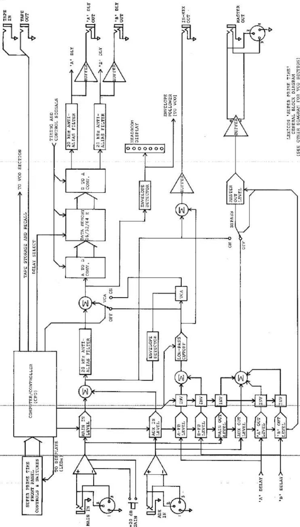
flowchart
graph TD
    A["SUPER PRIME TIME FRONT PANEL CONTROLS & SWITCHES"] --> B["TO DISPLAYS (LEDs)"]
    B --> C["COMPUTER/CONTROLLER (CPU)"]
    C --> D["TAPE STORAGE AND RECALL"]
    C --> E["DELAY SELECT"]
    D --> F["TO VCO SECTION"]
    E --> G["Timing AND CONTROL SIGNALS"]
    G --> H["A TO D CONV."]
    H --> I["DATA MEMORY 16/32/64 K"]
    I --> J["D TO A CONV."]
    J --> K["20 kHz ANTI-ALIAS FILTER"]
    K --> L["20 kHz ANTI-ALIAS FILTER"]
    L --> M["BUFFER"]
    M --> N["'A' DLY OUT"]
    M --> O["'B' DLY OUT"]
    P["MAIN IN"] --> Q["+"]
    R["+20 dB GAIN"] --> S["+"]
    T["AUX IN"] --> U["+"]
    V["AUX IN"] --> W["+"]
    X["AUX IN"] --> Y["+"]
    Z["AUX IN"] --> AA["+"]
    AB["AUX IN"] --> AC["+"]
    AD["AUX IN"] --> AE["+"]
    AF["AUX IN"] --> AG["+"]
    AH["AUX IN"] --> AI["+"]
    AJ["AUX IN"] --> AK["+"]
    AL["AUX IN"] --> AM["+"]
    AN["AUX IN"] --> AO["+"]
    AP["AUX IN"] --> AQ["+"]
    AR["AUX IN"] --> AS["+"]
    AT["AUX OUT LEVEL"] --> AU["INV"]
    AU --> AV["LOK-PASS CUTOFF"]
    AV --> AW["VCA"]
    AX["AUX OUT LEVEL"] --> AY["INV"]
    AY --> AZ["Σ"]
    BA["'A' OUT LEVEL"] --> BB["INV"]
    BB --> BC["Σ"]
    BD["'B' OUT LEVEL"] --> BE["INV"]
    BE --> BF["Σ"]
    BG["'A' DELAY"] --> BH["INV"]
    BI["'B' DELAY"] --> BJ["INV"]
    BK["'A-FB LEVEL"] --> BL["INV"]
    BL --> BM["LOK-PASS CUTOFF"]
    BM --> BN["VCA"]
    BO["'D-FB LEVEL"] --> BP["INV"]
    BP --> BQ["LOK-PASS CUTOFF"]
    BX["'A' OUT LEVEL"] --> BY["INV"]
    BY --> BZ["LOK-PASS CUTOFF"]
    CA["'B' OUT LEVEL"] --> CB["INV"]
    CB --> CC["LOK-PASS CUTOFF"]
    CD["'A' DLY"] --> CE["ENVELOPE DETECTOR"]
    CE --> CF["HEADROOM DISPLAY"]
    CG["'B' DLY"] --> CH["ENVELOPE POLLOWER [TO VCO"]]
    CI["'IN-MIX OUT"] --> CJ["BUFFER"]
    CJ --> CK["HASTER OUT LEVEL"]
    CL["'MASTER OUT"] --> CM["BUFFER"]
    CM --> CN["HASTER OUT LEVEL"]
    CO["'Tape OUT"] --> CP["TAPE STORAGE AND RECALL"]
    CP --> D
7.4 FRONT PANEL SETTINGS CORRESPONDING TO FACTORY PRESET EFFECTS
NOTE: Where level controls are not shown, adjust as required.
○ Indicates that LED is lit.
lexicon
programmable
digital delay processor
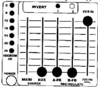
INPUT MIX
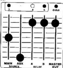
OUTPUT MIX
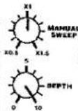

SUPER PRIME TIME
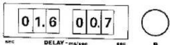


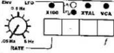
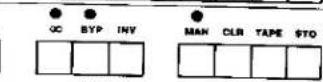
Factory Preset #1 - Basic Flanging
lexicon
programmable
digital delay processor

INPUT MIX
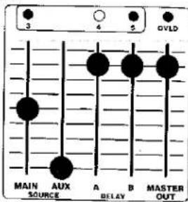
OUTPUT MIX

SUPER PRIME TIME



Factory Preset #2 - Resonant Flanging
lexicon
programmable
digital delay processor

INPUT MIX
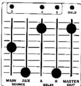
OUTPUT MIX

SUPER PRIME TIME


Factory Preset #3 - Doubling
lexicon
programmable
digital delay processor

INPUT MIX
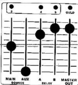
OUTPUT MIX
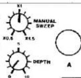
SUPER PRIME TIME
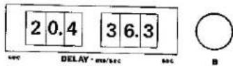


Factory Preset #4 - Trebling

Factory Preset #5 - Chorusing

Factory Preset #6 - Slap Echo

Factory Preset #7 - Echo
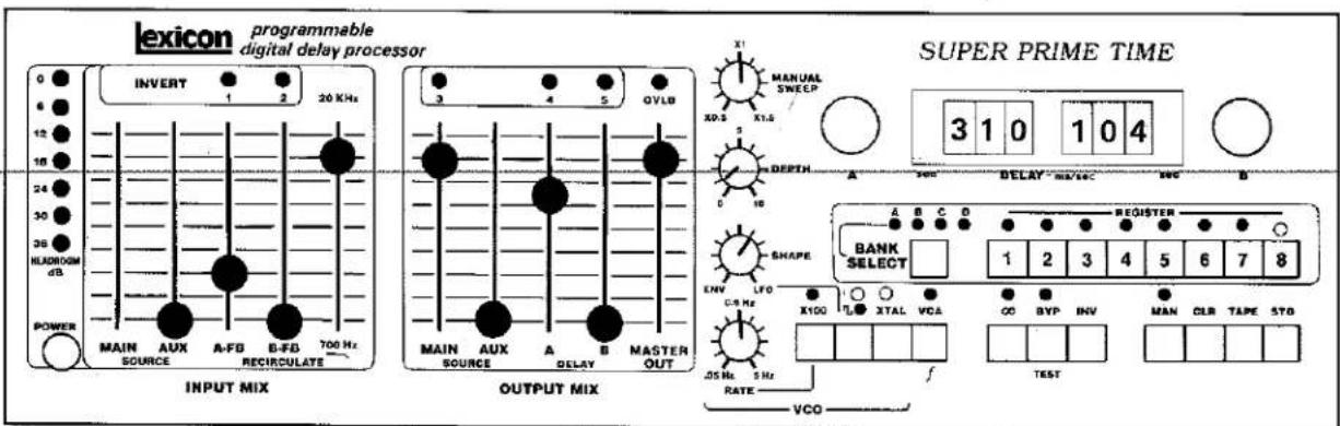
Factory Preset #8 -- Echo with Recirculation
8.1 GENERAL
Before you attempt to verify whether there is a genuine problem with the unit, it is important that you understand the operating and installation information presented in this manual. If it still doesn't work, jump up and down, yell, and then read the rest of the Section to see if you can pinpoint the problem.
WARNING
All servicing of the Model 97 should be performed by qualified service personnel. There are hazardous voltages located under both the top and bottom covers of the unit. To avoid electrical shock, remove the power cord prior to removing covers. Servicing procedures consistent with good safety practices should be used at all times. Additionally, due to the susceptibility of the CMOS integrated circuit chips to static discharge, improper handling of circuitry even with power disconnected can cause expensive damage to the Model 97.
8.2 UNIT WILL NOT POWER UP
If the Model 97 will not power up, first check the AC line cord to ensure it is securely plugged into the rear panel and the service outlet. Then check the fuse and verify that the service outlet is "live" and that the voltage is correct for the Model 97 (use a voltmeter, neon test light, or a common lamp). If correct voltage is present, unplug the Model 97, and refer the problem to a Lexicon authorized service technician (who should also check to make sure the internal line voltage switches are properly set), or return the unit to Lexicon (see Section 8.4).
8.3 UNIT POWERS UP, BUT WILL NOT PASS AUDIO
8.3.1 Check Cables
Check all audio cables to be sure they are securely plugged into the proper jacks. If the connections are good, check the cables themselves. Look for continuity and shorts between conductors while flexing the cable to check for intermittent contacts.
8.3.2 Check Other Sound Equipment in System
If all cables are good, the next step is to check the rest of the equipment in the sound system to ensure it is indeed operating properly. Unplug
the Model 97 output cable(s) at both ends, and set it aside. Then unplug the cable from the Model 97 input and instead connect it to the point which had been fed by the Model 97 output. This bypasses the Model 97 entirely. If the audio now passes through the sound system, the problem resides in the Model 97; if audio still does not pass, there is a problem elsewhere, and probably not in the Model 97.
8.3.3 Check Model 97 Control and Switch Settings
Be sure the rear-panel MAIN INPUT GAIN switch (0/+20 dB) is set properly, as well as the front panel INPUT MIX and OUTPUT MIX controls. Also, be sure the unit is not in INFINITE REPEAT mode, since it may be "holding" no signal at all. Try using a preset effect rather than your own setups.
8.4 UNIT POWERS UP, AND THEN "DOES ITS OWN THING"
The Model 97 is fully microprocessor controlled; nearly all front panel knobs, buttons, switches and indicators operate indirectly, relying upon the built-in computer to interpret the settings. If there is something amiss in the internal CPU interface or in the CPU itself, any number of odd symptoms could result. The chances are that a very strange malfunction is really a memory failure. Fortunately, we have built diagnostic software into the Model 97 to expedite troubleshooting and repair (see Section 8.7). You might suspect certain "typical" problem causes such as poor or intermittent grounding, excessive noise riding on the AC power line, or a loose circuit card.
8.5 UNIT CANNOT RECALL STORED PROGRAMS
When you store an effect in any of the 32 user-accessible memory registers, you are actually placing it in RAM (random access memory). RAM is normally volatile, meaning it disappears when power is shut off, but the Model 97 contains a NiCad battery to provide continuous power to the memory registers. If you've not used the Model 97 for a long period, or if the unit is several years old, the NiCad battery may be dead, which may explain the memory loss. If you suspect this, try leaving the Model 97 turned On for 24 hours; if the battery remains dead, it will have to be replaced. The loss of some memories but not others denotes a
different problem, most likely in the circuitry. On the other hand, be sure the effect was actually stored. A one-time loss of one or more memories which cannot be repeated may have been caused by a transient noise spike which "got through" the Model 97's extensive RFI and power supply filtering. In rare instances cosmic rays have been known to "zap" IC memories.
8.6 UNIT WILL NOT STORE (OR RECALL) MEMORIES FROM TAPE
If the Model 97 will not store its memory onto tape, check the cable to the recorder and make sure the recorder is in record mode with the input level set appropriately. With a cassette unit, be sure the "protect tab" is intact, and with reel-to-reel tape, be sure the oxide side is against the heads. Still no recording? Check the signal at the TAPE STORE OUT jack; it should be a steady tone at line level until the actual "write" instruction is punched in on the front panel, at which time it should change to a multi-tone frequency shift modulated signal for about a minute and a quarter (slightly less if only one bank is being stored). If this signal is not present, or is severely attenuated, there is a problem in the Model 97.
There are several reasons why, if the memory contents appear to be written on the tape, they may not read back into the Model 97. For one thing, if you try to recall a memory with a specific numerical flag (1 through 88), and the taped memory is not so numbered, then the Model 97 will ignore the read instruction. If you know the taped memory is numbered, but you don't know the number, just instruct the Model 97 to read the tape without specifying a numerical flag. If that is not the problem, look into the speed accuracy and wow/flutter spec of the tape recorder; try recording the steady tone present at the TAPE STORE OUT jack when the Model 97 is operating normally, and if, upon playback, the tone sounds shaky, then the recorder's performance is probably the culprit. Also, check the tape for possible dropouts. It goes without saying that the cable from the recorder's line output to the Model 97 TAPE STORE IN jack should be checked, the recorder output should be switched to monitor the tape (not source), and the output level should be turned up. If after checking these items you still cannot find a cause, it probably lies in the Model 97's circuitry.
8.7 DIAGNOSTIC SOFTWARE
There are several diagnostic routines permanently stored in the Model 97. These are primarily of value to factory or factory trained service personnel, but they can be accessed by the user to aid in identifying whether there is a problem. Should you telephone the factory for service assistance, the routines may help us to clearly identify the problem and to possibly arrange for more expeditious field servicing.
The diagnostic routines are accessed by simultaneously pressing in and holding the BYP button, then pressing and also holding the VCA button, and then pressing one of the REGISTER buttons. DO NOT DO THIS UNLESS YOU FIRST TURN OFF THE AUDIO EQUIPMENT CONNECTED TO THE MODEL 97 OUTPUT. The diagnostic loops are intended for troubleshooting with an oscilloscope and/or signature analyzer, and possibly other specialized gear. They cause extreme disturbance in the audio output. The diagnostic routines are of little value to the user, and, at the very least, should not be used with monitor levels turned up. Caveat auditor!
Escape to normal operation is accomplished by hitting MAN, and holding the button for about a second (the processor is being distracted). Then press MAN once more.
Here is a brief description of the diagnostics:
(Remember to hold in BYP, then press and also hold VCA, then press one of the REGISTER buttons and release all 3 buttons.)
BYP + VCA + REGISTER 1 = Diagnostic Loop 1 (factory service)
BYP + VCA + REGISTER 2 = Diagnostic Loop 2 (factory service)
BYP + VCA + REGISTER 3 = Diagnostic Loop 3 (factory service)
BYP + VCA + REGISTER 4 = Partial test of the tape interface functions. Normally, the display will go blank, except for the digit "0". Then the digit will begin to count slowly up in hexadecimal. If the digit does not begin to count, this indicates the tape interface is not functional. (Use MAN to escape; audio is disturbed.)
BYP + VCA + REGISTER 5 = Causes all panel lamps and LEDs to turn On at once (except the OVLD and HEADROOM LEDs). It tests for bad LEDs. (Use MAN to escape.)
BYP + VCA + REGISTER 6 = This tests the pot reading capabilities of the central processing unit (CPU).
When any control is rotated to its maximum clockwise position, the digital display will show a code "q q 0" on the left and "0 n n" on the right, where q is the hexadecimal number unique to the pot, and n n is the value being read on the pot, also in hexadecimal. The display will hold the same pot until another is activated by turning it to maximum clockwise position. (Use MAN to escape.)
BYP + VCA + REGISTER 7 = This tests the switch reading capability of the CPU, similar to the above pot interpretation test. The display is "0 0 0" "0 p p", where p p is the code unique to each key. (Use MAN to escape.)
BYP + VCA + REGISTER 8 = This is a test of the CPU's Random access memory (RAM) area (not the delay memory). If RAM is OK, the display will blink brightly for an instant and then return to normal. If the RAM is bad, the display is "E__". Call the factory on this one.
8.8 RETURNING UNITS FOR REPAIR
If it becomes necessary to return your Model 97 for service, bear in mind that Lexicon assumes no responsibility for units in shipment from customer to factory, whether or not they are in warranty. It is important, therefore, that shipments be well packed, properly insured, and consigned to a reliable agent such as UPS or Federal Air Express. Be sure to include (inside the carton) a note explaining the nature of the problem, referencing any conversation with Lexicon personnel you may have had. Also, detail the preferred return shipping method, and indicate a date when the unit is again needed. Do not include accessories such as power cords, manuals, and remote switches. It is also important to provide Lexicon with the name and telephone number of a person we may contact should any questions arise.
8.9 REPLACEMENT PARTS
Replacement parts and the service manual may be ordered from:
Lexicon, Inc.
60 Turner Street
Waltham, MA 02154
U.S.A.
Attn: Customer Service
Telephone: (617) 891-6790 TWX 923 468
Subject to order approval by Lexicon, parts will be shipped F.O.B. Waltham. Charges will be that price in effect at the time the order is received. Lexicon may be consulted at any time, during business hours, for a parts quotation.
When ordering parts, refer to the appropriate parts list in the Model 97 Service Manual, or order by complete description and give the following information:
A. Part ID number, if available.
B. Item description (e.g., RATE control knob, etc.)
C. Quantity desired.
D. The model and serial number of the unit.
8.10 LIMITED WARRANTY
Lexicon, Inc., warrants each Model 97 to be free from defects in material and workmanship for one year, under normal use and service. This warranty begins on the date of delivery to the purchaser or his authorized agent or carrier. During the warranty period Lexicon will repair or, at its option, replace at no charge, components that prove to be defective, providing the equipment is returned, shipping prepaid, to Lexicon or designated service facility.
This warranty is null and void under any of the following conditions:
A. Abuse, neglect, alteration, tampering, or repair by unauthorized personnel.
B. Damage caused by improper use, or operation from an incorrect power source.
C. Damage caused by accident, act of God, war, or civil-insurrection. Lexicon shall not be responsible for
any loss or damage, direct or consequential, resulting from Model 97 failure or the inability of the product to perform. Lexicon shall not be responsible for any damage or loss during shipment to or from the factory or its designated service facility.
This warranty is in lieu of all other warranties, express or implied, and of any other liabilities on Lexicon's part,
and Lexicon does not assume or authorize anyone to make any warranty or assume any liability not strictly in accordance with the above.
Lexicon reserves the right to make changes or improvements in the design and construction of the Model 97 without obligation to make such changes or improvements to the purchaser's unit.
No equipment may be returned under this warranty without prior authorization from Lexicon. Authorized return shipments must be prepaid and should be insured. System modules being returned for repair/ exchange should be wrapped or packed in soft packing material and shipped in an appropriate small protective box. In the case of returning the entire Model 97, it should be carefully packed in the original carton and packing material. If this is not available, new packing may be procured from Lexicon.
BLANK PATCH DIAGRAMS for user convenience.
(We recommend photocopying or instant printing a quantity of these pages if you plan to log many settings.)


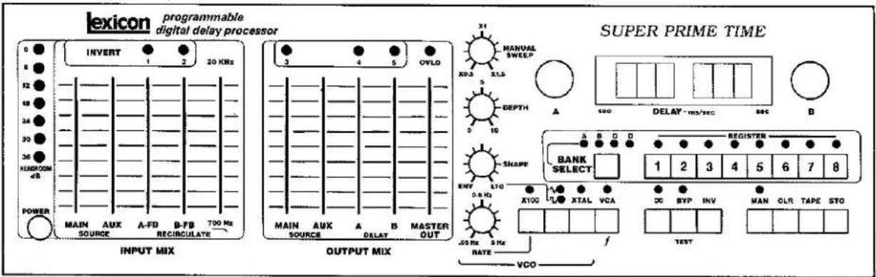

lexicon
programmable
digital delay processor
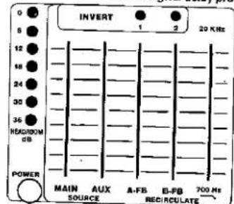
INPUT MIX

OUTPUT MIX
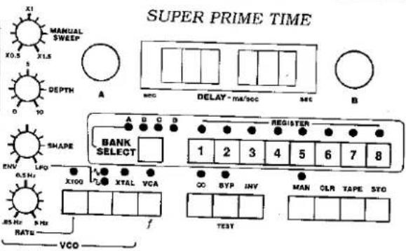

lexicon
programmable
digital delay processor

INPUT MIX

OUTPUT MIX


lexicon
programmable
digital delay processor
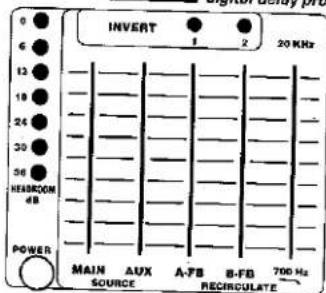
INPUT MIX

OUTPUT MIX

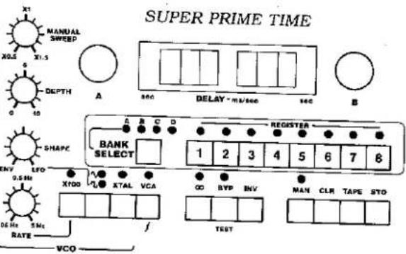
lexicon
programmable digital delay processor

INPUT MIX

OUTPUT MIX

- programmable digital delay processor
- Owner's Manual
- Unpacking & Inspection
- SECTION ONE Introduction
- GENERAL
- ABOUT THIS MANUAL
- PRECAUTIONS
- WARNING
- Controls & Indicators
- GENERAL
- POWER switch
- HEADROOM display
- INPUT MIX Section
- MAIN SOURCE control
- AUX SOURCE control
- A-FB control
- B-FB control
- Recirculation low pass filter (700 Hz - 20 kHz)
- OUTPUT MIX section
- MAIN SOURCE control
- AUX SOURCE control
- A-DELAY control
- B-DELAY control
- MASTER OUT control and OVLD indicator
- INVERT indicators
- INVERT (1, 2, 3, 4 and 5)
- VCO section
- MANUAL SWEEP control
- DEPTH control
- SHAPE control, plus √ √ (sine/square) button and indicators
- RATE control, X100 button and indicator
- XTAL button and indicator
- Additional Signal Processing Pushbuttons
- VCA/FUNCTION button and indicator
- ∞ button and indicator
- BYP/TEST button and indicator
- INV button
- DELAY time controls and readout
- "A" DELAY control
- DELAY (mS/sec) readout
- "B" DELAY control
- Memory Assignment Section
- BANK SELECT button and indicators
- REGISTER buttons and indicators
- Mode control buttons
- MAN (manual) button and indicator
- CLR (clear) button
- TAPE button
- STO (store) button
- REAR PANEL
- Signal inputs and outputs
- MAIN INPUT connectors and GAIN switch (0 dB / +20 dB)
- AUX INPUT connectors
- UNBALANCED OUTPUT connectors (INPUT MIX, DELAY-A, DELAY-B)
- MASTER OUTPUT connectors
- Remote Control connections
- EXTERNAL DELAY SWEEP jack
- MODULATION OUT jack
- MODULATION IN jack
- RATE IN jack
- BYPASS jack
- oo REPEAT jack
- REGISTER STEP jack
- TAPE STORE IN jack
- TAPE STORE OUT jack
- Power connector
- FUSE holder
- SECTION THREE
- Installation
- MOUNTING
- POWER REQUIREMENTS
- AUDIO SIGNAL CONNECTIONS
- REMOTELY CONTROLLED FUNCTIONS
- BYPASS
- INFINITE REPEAT
- REGISTER STEP
- EXTERNAL DELAY SWEEP
- RATE IN
- MODULATION OUT and IN jacks
- TAPE STORE IN AND OUT
- GENERAL
- TURNING ON THE MODEL 97
- "BUILT IN" EFFECTS
- CALIBRATING THE FRONT PANEL TO ANY RECALLED EFFECT
- ABOUT THE DELAY TIME DISPLAY AND SETTINGS
- INPUT MIX CONTROLS
- OUTPUT MIX CONTROLS
- INVERTING THE POLARITY OF RECIRCULATION AND OUTPUT SIGNALS
- STORING, RECALLING, COPYING AND CLEARING YOUR OWN EFFECTS IN MEMORY
- WRITING THE MEMORIES ON MAGNETIC TAPE (CREATING A FILE)
- VERIFYING THAT MEMORIES ARE ACCURATELY STORED ON TAPE
- READING A FILE FROM THE TAPE
- GENERAL
- THE VCO (VOLTAGE CONTROLLED OSCILLATOR) AND ITS ASSOCIATED FUNCTIONS (MANUAL SWEEP, XTAL MODE, AND THE LFO SECTION)
- USING THE LFO
- DYNAMIC RECIRCULATION (AND THE VCA BUTTON)
- CROSS FADING BETWEEN EFFECTS (AND THE VCA BUTTON)
- INFINITE REPEAT
- USING A REMOTE SWITCH TO ADVANCE THROUGH THE MEMORY REGISTERS
- USING RECORDED CUES TO ADVANCE THROUGH THE MEMORY REGISTERS
- REMOTE BYPASSING SWITCHING
- REMOTE CONTROL OF THE LFO RATE OR THE VCO MANUAL SWEEP
- REMOTE CONTROL (OR LINKAGE) OF THE LFO's MODULATION
- WHERE TO USE THE MODEL 97 — BASIC SETUPS
- GENERAL APPLICATIONS FOR DELAY LINES
- Flanging (Preset BANK, REGISTER #1)
- Resonant Flanging (Preset BANK, REGISTER #2)
- Doubling (Double Tracking) (Preset BANK, REGISTER #3)
- Trebling (Triple Tracking) (Preset BANK, REGISTER #4)
- Long Delay Effects (Preset BANK, REGISTER #5)
- Echo (Preset BANK, REGISTERS #6 & #7)
- Echo with Recirculation (Preset BANK, REGISTER #8)
- Rhythmic Effects
- Vibrato
- Pitch Twisting Effects
- Resonant Effects
- Infinite Repeat Effects
- CHROMATIC TUNED RESONANCES
- USING TWO MODEL 97's (OR THE MODEL 97 WITH ANOTHER LEXICON DELAY PROCESSOR) FOR ADDITIONAL SPECIAL EFFECTS PROCESSING
- Stereo Processing with coupled LFO modulation as well as coupled memory
- Series Connection of two Model 97s for compound effects or longer overall delays.
- Parallel Connection of two Model 97s for deep tape phasing effects (the ultimage flange)
- TAKING FULL ADVANTAGE OF THE MODEL 97 IN RECORDING
- Synchronous register stepping from cues on a multi-track tape.
- Using the DELAY A OUT and DELAY B OUT jacks
- USING THE MODEL 97 IN VIDEO AND FILM POST PRODUCTION AUDIO
- LOCALIZATION AND IMAGE PLACEMENT
- AVOIDING ECHOES IN DISTRIBUTED SOUND REINFORCEMENT SYSTEMS
- TIPS ON PROGRAMMING EFFECTS FOR LIVE PERFORMANCE
- EVOLVING PREVIOUSLY STORED EFFECTS INTO NEW ONES
- GENERAL PERFORMANCE, CONTROLS AND INDICATORS
- INTERFACE INFORMATION
- FRONT PANEL SETTINGS CORRESPONDING TO FACTORY PRESET EFFECTS
- GENERAL
- UNIT WILL NOT POWER UP
- UNIT POWERS UP, BUT WILL NOT PASS AUDIO
- Check Cables
- Check Other Sound Equipment in System
- Check Model 97 Control and Switch Settings
- UNIT POWERS UP, AND THEN "DOES ITS OWN THING"
- UNIT CANNOT RECALL STORED PROGRAMS
- UNIT WILL NOT STORE (OR RECALL) MEMORIES FROM TAPE
- DIAGNOSTIC SOFTWARE
- RETURNING UNITS FOR REPAIR
- REPLACEMENT PARTS
- LIMITED WARRANTY
Brand : LEXICON
Model : M97
Category : Effects machine