
0070-10406 - Video recorder Ernitec - Free user manual and instructions
Find the device manual for free 0070-10406 Ernitec in PDF.


| Product Type | Digital Video Recorder (DVR) |
| Brand | Ernitec |
| Model | 0070-10406 |
| Dimensions (W x H x D) | 300 mm x 200 mm x 50 mm |
| Weight | 1.5 kg |
| Power Supply | 12V DC, 2A (adapter included) |
| Power Consumption | ≤ 10W |
| Video Inputs | 4 BNC connectors (for analog cameras) |
| Video Output | 1 HDMI, 1 VGA |
| Recording Resolution | Up to 1080p (1920x1080) |
| Compression Format | H.264/H.265 |
| Hard Drive Support | 1 SATA HDD up to 8TB (not included) |
| Network Interface | 1 RJ45 10/100 Mbps Ethernet |
| Remote Access | Via mobile app (iOS/Android) and web browser |
| Motion Detection | Yes, configurable per channel |
| Playback Modes | By time, by event, smart search |
| Operating Temperature | 0°C to 40°C |
| Storage Temperature | -20°C to 60°C |
| Cleaning Instructions | Use a soft, dry cloth; no liquids or solvents |
| Safety Instructions | Avoid moisture, extreme heat, and direct sunlight. Do not block ventilation slots. |
| Spare Parts | Power adapter, remote control, mounting screws, SATA cable |
| Repairability | Replaceable hard drive and power supply unit; fuse on mainboard |
| Certifications | CE, FCC, RoHS |
Frequently Asked Questions - 0070-10406 Ernitec
User questions about 0070-10406 Ernitec
0 question about this device. Answer the ones you know or ask your own.
Ask a new question about this device
Download the instructions for your Video recorder in PDF format for free! Find your manual 0070-10406 - Ernitec and take your electronic device back in hand. On this page are published all the documents necessary for the use of your device. 0070-10406 by Ernitec.
USER MANUAL 0070-10406 Ernitec
natural_image
Line drawing of a rectangular electronic device with ventilation slots and a labeled 'HDMI' logo (no text on device itself)NVR 32 channel
Quick Setup Guide
Item no: 0070-10404
Precautions
Fully understand this document before using this device, and strictly observe rules in this document when using this device. If you install this device in public places, provide the tip "You have entered the area of electronic surveillance" in an eye-catching place. Failure to correctly use electrical products may cause fire and severe injuries.
| WARNING | It alerts you to moderate dangers which, if not avoided, may cause minor or moderate injuries. |
| CAUTION | It alerts you about risks. Neglect of these risks may cause device damage, data loss, device performance deterioration, or unpredictable results. |
| NOTE | It provides additional information. |
WARNING
Strictly observe installation requirements when installing the device. The manufacturer shall not be liable for device damage caused by users' non-conformance to these requirements.
Strictly conform to local electrical safety standards and use power adapters that are marked with the LPS standard when installing and using this device. Otherwise, this device may be damaged.
Use accessories delivered with this device. The voltage must meet input voltage requirements for this device.
If this device is installed in places with unsteady voltage, ground this device to discharge high energy such as electrical surges in order to prevent the power supply from burning out.
When this device is in use, ensure that no water or any liquid flows into the device. If water or liquid unexpectedly flows into the device, immediately power off the device and disconnect all cables (such as power cables and network cables) from this
device.
If this device is installed in places where thunder and lightning frequently occur, ground the device nearby to discharge high energy such as thunder strikes in order to prevent device damage.
CAUTION
Avoid heavy loads, intensive shakes, and soaking to prevent damages during transportation and storage. The warranty does not cover any device damage that is caused during secondary packaging and transportation after the original packaging is taken apart.
Protect this device from fall-down and intensive strikes, keep the device away from magnetic field interference, and do not install the device in places with shaking surfaces or under shocks.
Clean the device with a soft dry cloth. For stubborn dirt, dip the cloth into slight neutral cleanser, gently wipe the dirt with the cloth, and then dry the device.
Do not jam the ventilation opening. Follow the installation instructions provided in this document when installing the device.
Keep the device away from heat sources such as radiators, electric heaters, or other heat equipment.
Keep the device away from moist, dusty, extremely hot or cold places.
If the device is installed outdoors, take insect- and moisture-proof measures to avoid circuit board corrosion that can affect monitoring.
γRemove the power plug if the device is idle for a long time
When unpacking, please first confirm whether fragile label is damaged, if damaged, please contact customer service or sales personnel in time. The company will not be liable for any human-made damage to fragile labels
Special Announcement
All complete products sold by the manufacturer are delivered along with nameplates, quick setup guide and accessories after strict inspection. The manufacturer shall not be liable for counterfeit products.
The manufacturer will update this manual according to product function enhancement or changes and regularly update the software and hardware described in this manual. The updated content will be added to new versions of this manual without prior notice.
This manual may contain misprints, technology information that is not accurate enough, or product function and operation description that is slightly inconsistent with the actual product, the final interpretation of company is as a standard.
This manual is only for reference and does not ensure that the information is totally consistent with the actual product. For consistency, see the actual product.
NOTE
For more information, please refer to our website.
1 Open Package Examination
Open the package, check the appearance of product for no obvious damage, and confirm the item list for table 1-1 is consistent.
Table 1-1 Packing list
| Component | Quantity | Remark |
| Network video recording | 1 | |
| Quick Setup Guide | 1 | |
| Mouse | 1 | |
| Green female wiring terminal | 2(B) | |
| Power Cord | 1 | |
| Hanger | 2 | |
| Countersunk head black screws | 6 | |
| Countersunk head imperial while screws | 24 |
2 Device Structure
2.1 Device Ports
NOTE
Different devices may have different ports and multi-head cables; Please refer to the actual product.
For front panel description of device refer to table 2-1
Table 2-1 Front panel description
| Port Name | Description |
| PWR Indicator | When the NVR is operating, the PWR indicator is steady on. When the NVR is shut down, the PWR indicator is off. |
| HDD Indicator | Hard disk status indicator. This indicator flashes when data is transmitted. |
| PoE Indicator | PoE network status indicator. This indicator flashes when data is transmitted. |
| USB 2.0 | Support connected to an USB mouse or USB disk. |
For rear panel description of device, please refer to table 2-2. Table 2-2 Rear panel description
| Port Name | Description |
| WAN | RJ 1000 Mbps adaptive Ethernet interface, connect to Internet. |
| LAN | RJ 1000 Mbps adaptive Ethernet interface, connect to intranet to add cameras. |
| Audio put/ Audio in | Audio output and audio input. |
| VGA | Video output interface. If the Auxiliary Screen is enable, HDMI1's output is main screen, VGA's output is auxiliary screen. |
| HDMI1/2 | |
| e SATA | External hard disk interface. |
| USB 3.0 | Support connected to 3.0 U disk. |
| RS232 | Standard Rs232 serial communication interface of the device. |
| ALARM I/O RS 485 | Alarm input and alarm output, 1A&1B~4A/4B are alarm out. A is RS 485+, B isRS485-. |
| Safe ground screw of the device. | |
| Power switch. | |
| AC 110V/220V power input interface. |
2.2 Device Dimensions
NOTE
Different devices may have different dimensions; Please refer to the actual product.
Figure 2-1 Dimensions (Unit:mm)

3 Device Installation
The hard disk of the NVR must be provided by the user. Take the following steps to install the hard disks:
Step 1 Remove the screws for fixing the cover and take down the cover.
Step 2 Put the hard disk under the hard disk bracket, hold the hard disk with one hand and aim the hard disk hole at the bracket hole, then fix the screws for hard disk(Install the hard disk near the fan first).
Figure 3-1 Instelling the hard disk

Step 3 Repeat step 2 to install other hard disks, and insert the hard disk data cables and power cables, then replace the upper cover and fasten the fixing screws.
Device Operation
4.1 Startup
Before starting NVR, ensure that the NVR is connected to a power supply properly and a monitor is connected to the HDMI or VGA interface of the NVR correctly. After starting the NVR, there is a login window located in the center, as shown in figure 4-1.
In some environments, if the power supply is abnormal, the NVR may not work properly. In severe cases, the NVR may be damaged. In these environments, it is recommended to use regulated power supply.
Figure 4-1 Activation interface
Figure 4-2 Login interface


NOTE
- The default name is admin, and NVR needs to activate, please create
new password of devices and channels to activation
? Users can change the system display language on the login window
4.2 Topology of the NVR
For the cameras and NVR device are on Internet, or at same network. NVR and IP cameras can communicate with each other smoothly with WAN port. Figure 4-3 shows the network topology of the NVR.
Figure 4-3 Topology of the NVR

4.3 Special Function
Some functions are applicable for some special cameras, such as Microphone, Human thermometer. Smart, Intelligent Analysis, Advanced Intelligent Analysis, please refer to actual camera channels.
4.4 Power off
Enter the Main Menu >System >Maintenance >Shutdown to power off the NVR. Or turn off the power switch
4.4 Quick menu
Put the mouse arrow on bottom of live video interface, the quick menu will be showing. You can set layout to view live video, switch the split screen, auto sequence, playback and so on.

5 Quick Configuration
Plug in power to access the NVR user page. The wizard window would show at first time, users can configure quickly or close immediately. For configuration details please refer to main menu.
Right-click on the main interface at any where to access the main menu. Main menu comprises Channel, Record, Alarm, Network and System settings, as shown in figure 5-1.
Figure 5-1 Main menu

5.1 Channel
Channel settings contain Camera, Encode, Image, OSD, Privacy Zone, ROI (region of interest), Microphone, Human thermometer, Smart, and Intelligent Tracking.
Camera: Users can add cameras automatically by clicking Click to Add, and add manually by clicking Add. Tick cameras then click Delete to delete cameras. Users can batch update software or Encode: Users can set stream, encode type, resolution, frame rate, bit rate type, bit rate and so on.
y Sensor setting: Adjust image parameters and users can set
senor parameter:
OSD: Customer time and channel name connecting in the live
- CSS: Customize this and channel name displaying in the video page.
Y Privacy Zone: Set a privacy zone by clicking ana dragging cursor and double-click an exist private area to delete it. Support up to 4 zones.
? Some of these settings can be copied to other channels by
clicking Copy button.
Y Microphone, Human Thermometer. Smart, and Intelligent Tracking are the special functions for some models, not applicable for all cameras.
5.2 Record
Record settings contain Record Schedule, Disk, Storage, RAID, S.M.A.R.T. Disk Detection, Disk Calculation and FTP.
Record Schedule: Set record schedule and storage strategic. ANR is auto network recording, if the camera is plugged SD card and enabled record, if camera is disconnected, when the connection is recovered. NVR will copy the recording of the lost videos.
Enter S.M.A.R.T interface to view the state of disks. Disk
RAID: If users install more than four disks and want to keep the data safety, it is recommended to build RAID.
YDisk Detection: Check the disk health status
Y Disk Calculation: Two Methods to calculate Y FTP: File Transfer Protocol, set the FTP path to save the alarm information if linkage to FTP.
NOTE
Format the disk and all data on disk will be lost, please be
Before replacing the hard disk, the power must be turned off. The disks of building RAID should be enterprise level, and the capacities are better at the same.
For the safety of disks, please make sure the stabilization of
(1) 2017年1月1日
(1)公司负责人
Alarm settings contain General, Motion Detection, Video Loss, Advanced Intelligent Analysis, Intelligent Analysis, Alarm in, Abnormal Alarm. Alarm out and Local intelligent analysis, as shown in figure 5-2.
Figure 5-2 Alarm

? General: Enable or disable alarm and set duration time of alarm and buzzer.
? Motion Detection: Enable this function, if detects any
movement, it will alarm. 1. Event actions: Contain burses alarm out push messages to
-
Event buttons: 600m BUL25, that in out, push message to App, pop-up message to monitor, send E-mail and post recording (after enabling, choose the recording time from drop list.)
-
Area: Set motion detection area. Press left button and drag the cursor to add a detection area, and double-click an area to delete it.
-
Schedule: Set schedule to enable or disable motion detection alarm. There are three methods to set: the first is clicking the double arrows button to choose all day. The second, click and drag the cursor to select periods. The third, click one by one.
Y Video Loss, Intelligent Analysis are same settings as motion detection. Advanced Intelligent Analysis is used for thermal cameras, alarms for smoke detection, smoke and flame detection and fire spot detection.
- Alarm In / Alarm out: Settings for I/O alarming. Abnormal Alarm can tick disk error, IP conflict, network disconnected. - Local Intelligent Analysis: It is up to be set for 4 channels, set local intrusion parameter on NVR.
5.4 Network
Network settings contain Network, 8021X, DDNS, E-mail, Port Mapping, P2P, IP Filter, SNMP. 3G/4G, PPPoE, Network Traffic and Platform Access, as shown in figure 5-3.
Figure 5-3 Network

Y Network, 802.1X, DDNS, and SNMP interface to set network parameters
? Email: Set E-mails for sending and receiving alarm messages and password retrieval message.
? Port Mapping: Set the ports for remote scanning. ? P2P: Add NVR into device list of App by accessing the QR code. ? IP Filter: Settings for creating black list or white list.
7 3G/4G. Use 3G/4G modem plug to NVR provide the network.
YPPPoE: Point to point network to access NVR directly. Y Network Traffic. View the send and receive rate of network. Y Platform Access: Set URL parameters for accessing to
CMS(Center Management System)
5.5 System
System settings contain information, General, User Account Security Center, Layout, Auxiliary Screen, Logs, Maintenance and Auto Reboot, as shown in Figure 5-4.
Figure 5-4 System
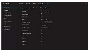
Y Information: View the basic information, such as System Network, Channels, Disk, Alarm.
General: include system, date and time, time zone, DST. ? User Account. Add users and set advance setting (auto login, password double authentication, boot wizard).
? Security Center. Modify the password, pattern unlock, secure Email. Secure question.
?Layout: Add layouts to preview live video of the channels. ?Auxiliary Screen: Use HDMI and VGA to view live video at the same time. HDMI port output acts as main screen.
γ Logs: Users can export logs (operating and alarm logs) if plug in a USB disk.
Maintenance. Include shutdown, reboot, exit system, reset,
import configuration, export configuration and update. Y Auto Reboot: Enable this function and the device will restart periodically.
5.6 Live Video
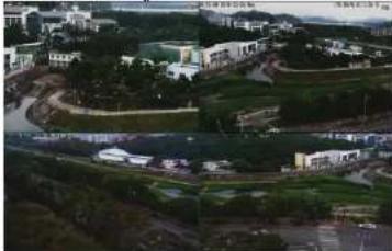
nter the user name and password in the login interface, and click Login to enter the real-time video interface. As shown in Figures 5-5.
Figure 5-5 Live video
natural_image
Aerial view of a residential area with buildings, roads, and green spaces (no visible text or symbols)6 MobileClient
Search for "InView Pro4" in App Store or Google Play to download and install the App. Use the App to scan the QR code, which you can find it on the backboard of the NVR and on P2P settings page (Main menu>Network>P2P) in user interface. Then input the NVR's user name and password to add the NVR to the device list. Users can manage the device on the APP.
7 Web Accessing
The NVR also can be accessed in a Web browser. Open a web browser like Chrome 45 and enter the IP address of device (The default IP address is 192.166.0.121) in the address box, and press Enter. The login page is displayed as shown in figure 7-1.
Figure 7-1 Login

NOTE
The user name and password are same as in the UI interface.
- Quick Setup Guide
- Precautions
- WARNING
- CAUTION
- Special Announcement
- NOTE
- Open Package Examination
- Device Structure
- Device Ports
- Device Dimensions
- Device Installation
- Device Operation
- Startup
- Topology of the NVR
- Special Function
- Power off
- Quick menu
- Quick Configuration
- Channel
- OSD: Customer time and channel name connecting in the live
- Record
- 2017年1月1日
- (1)公司负责人
- Network
- System
- Live Video
- MobileClient
- Web Accessing
Brand : Ernitec
Model : 0070-10406
Category : Video recorder