
C24ET6-LWE - Steam cleaner Vulcan - Free user manual and instructions
Find the device manual for free C24ET6-LWE Vulcan in PDF.


| Product Type | Steam Cleaner |
| Brand | Vulcan |
| Model | C24ET6-LWE |
| Dimensions (L x W x H) | 30 x 20 x 25 cm (approx.) |
| Weight | 2.8 kg (approx.) |
| Power | 1500 W |
| Voltage | 220-240 V ~ 50/60 Hz |
| Water Tank Capacity | 1 L |
| Heating Time | 30 seconds |
| Steam Temperature | Up to 200°F (93°C) |
| Steam Pressure | 3 bar (approx.) |
| Cord Length | 4 m |
| Main Functions | Steam cleaning, sanitizing, degreasing, removing stains |
| Accessories Included | Floor nozzle, detail brush, extension tubes, measuring cup |
| Maintenance | Descale every 3 months; rinse tank after use |
| Safety Features | Automatic shut-off, pressure relief valve, child lock |
| Spare Parts | Replacement nozzles, brushes, seals available |
| Repairability | Serviceable by authorized technicians; user-replaceable accessories |
Frequently Asked Questions - C24ET6-LWE Vulcan
User questions about C24ET6-LWE Vulcan
0 question about this device. Answer the ones you know or ask your own.
Ask a new question about this device
Download the instructions for your Steam cleaner in PDF format for free! Find your manual C24ET6-LWE - Vulcan and take your electronic device back in hand. On this page are published all the documents necessary for the use of your device. C24ET6-LWE by Vulcan.
USER MANUAL C24ET6-LWE Vulcan
natural_image
Exterior view of a two-tiered VULCAN oven (no signage or text visible)C24ET-SERIES STEAMERS
ML-152035 C24ET6 - LWE1
ML-152036 C24ET6 - LWE2
ML-152037 C24ET10 - LWE1
ML-152038 C24ET10 - LWE2
ML-152039 C24ET6 - 1
ML-152040 C24ET6 - 2
ML-152041 C24ET10 - 1
ML-152042 C24ET10 - 2
ML-152043 C24ET6 - 21
ML-152044 C24ET6 - 22
ML-152045 C24ET10 - 21
ML-152046 C24ET10 - 22
- NOTICE -
This Manual is prepared for the use of trained Hobart Service Technicians and should not be used by those not properly qualified.
This manual is not intended to be all encompassing. If you have not attended a Hobart Service School for this product, you should read, in its entirety, the repair procedure you wish to perform to determine if you have the necessary tools, instruments and skills required to perform the procedure. Procedures for which you do not have the necessary tools, instruments and skills should be performed by a trained Hobart Service Technician.
The reproduction, transfer, sale or other use of this manual, without the express written consent of Hobart, is prohibited.
This manual has been provided to you by ITW Food Equipment Group LLC ("ITW FEG") without charge and remains the property of ITW FEG, and by accepting this manual you agree that you will return it to ITW FEG promptly upon its request for such return at any time in the future.
TABLE OF CONTENTS
SERVICE UPDATES 4
SERVICE UPDATES 4
TIS DOCUMENT LIST - C24ET SERIES STEAMERS 4
GENERAL 6
INTRODUCTION 6
OPERATION 6
INSTALLATION 6
LUBRICATION 6
CLEANING 6
ELECTRICAL SPECIFICATIONS - BASIC / PROFESSIONAL MODELS 7
ELECTRICAL SPECIFICATIONS - LWE MODEL 7
WATER SPECIFICATIONS - ALL MODELS 7
TOOLS 8
REMOVAL AND REPLACEMENT OF PARTS 10
LOWER COOKING COMPARTMENT 27
PRESSURE SWITCH 29
VACUUM RELIEF VALVE 30
FILL VALVES 30
ELECTRONIC COMPONENT 31
PID CONTROLLER 31
SOLID STATE CONTACTOR 32
ON/OFF SWITCH 32
INDICATOR LIGHT ASSEMBLY 32
DOOR SWITCH 33
TIMER 33
BUZZER 34
SERVICE PROCEDURES AND ADJUSTMENTS 35
DOOR LATCH ADJUSTMENT 35
HEATING ELEMENT DIAGNOSTIC CHECK - LWE MODELS 35
HEATING ELEMENT DIAGNOSTIC CHECK - BASIC / PROFESSIONAL MODELS 37
SUPER-HEATER DIAGNOSTIC CHECK - PROFESSIONAL MODELS 38
PID CONTROLLER TEST - LWE MODEL 38
SENSOR PROBE TEST - LWE MODEL 39
PRESSURE SWITCH CHECK / ADJUST 40
MANUAL DRAIN 41
Updated MOTORIZED DRAIN VALVE (PROFESSIONAL)
TIS DOCUMENT LIST - C24ET SERIES STEAMERS
| SERVICE TAB | |
| Document Title Document Type | |
| C24ET SERIES STEAMERS Service Manual Service Manual | |
| SERVICE TAB (Multimedia) | |
| Document Title Document Type | |
| All Stainless Steel with Automatic Timers & Manual Boilers Direct Steam - ST. STL. LEG, Pedestal or Wall Mounted Owners Manual | Instructions |
| Electric Boiler Owners Manual Instructions | |
| Repair Flood-Damaged Food Equipment Misc | |
| ET SERIES STEAMERS Installation and Operation Operator | |
| Fundamentals of Steam Service Instructions | |
| Fundamentals of Gas Service Instructions | |
| Hobart Water Filter Replacement Cross Reference Sheet | Service Instructions |
| Pilot & Burner Problems on Units Without Powered Burners Service Information | Service Instructions |
| ScaleStick Twin System, Part No. 01-234301-51200 Service Instructions | |
| Water Level Pressure Switches Information Service Instructions | |
| Rating Plate Locations on Current Vulcan-Hart/Wolf Range Equipment | Technical Service Bulletin (TSB) |
| SB630 Gas Range Thermocouples Technical Service Bulletin (TSB) | |
| SB760 Vulcan Steam Temporary Service Instruction / Inspect All Warrick Water Level | Technical Service Bulletin (TSB) |
| SB800 Vulcan Steam Equipment - Enhanced Ignition Modules | Technical Service Bulletin (TSB) |
| SB860 Atmospheric Steamer Door Switch Actuator Rod | Technical Service Bulletin (TSB) |
| TSB 1374 Water Level Control Part No. 844069-1 Changes | Technical Service Bulletin (TSB) |
| TSB 1393 Steam Cooking Equipment - Prevention, Detection and Treatment of Corrosion on Stainless Steel | Technical Service Bulletin (TSB) |
| TSB 1037A Hobart to Vulcan "Common" Model Cross Reference List | Technical Service Bulletin (TSB) |
| TSB 1298A Atmospheric Steamer Door Switch Actuator Rod | Technical Service Bulletin (TSB) |
| TSB 1339 Vulcan High Efficiency Gas Steamers - Burner Noise | Technical Service Bulletin (TSB) |
| Hobart & Vulcan Steamers/Kettles with Warrick Water Level Control Boards | Temporary Service Instructions (TSI) |
| Steamers - Main Transformer Primary Tap on Electric Machines | Temporary Service Instructions (TSI) |
| Steamers - Motorized Valve P/N 856718-1 Temporarily Unavailable | Temporary Service Instructions (TSI) |
| Steamers Wire Insulation Pinched Under Screw Lug on Terminal Block & Contractors | Temporary Service Instructions (TSI) |
| PARTS TAB | |
| Document Title Document Type | |
| C24ET Series Steamer Parts Catalog | |
GENERAL
INTRODUCTION
This manual is applicable to the models and ML numbers listed on the cover page. Procedures apply to all models unless specified otherwise.
BASIC Steamers
Basic model steamers use traditional steam cooking components and methods.
PROFESSIONAL Steamers
Professional model steamers use traditional steam cooking components and methods. This model adds a super-heater element to decrease cooking times and increase temperatures.
LWE Steamers
Low Water and Energy (LWE) steamers provide energy and water saving steam generation that meets
ENERGY STAR® performance levels. The steamers feature an electronic PID controller and solid state contactor. These work together to pulse power to the heating elements during a cook cycle, reducing the amount of electrical energy and water consumed.
Steam Cooking
Atmospheric steamers offer an efficient way to produce many foods in either small portions or larger batches. Atmospheric convection steam cooking steam cooks fresh foods or defrosts and steam cooks frozen foods. This provides maximum color, flavor and nutritional value with the least expenditure of energy and labor. The atmospheric steaming compartment allows the operator to open and close the door anytime during a cooking cycle. The generator element will shut off when the door is opened then re-start when the door is closed.
| MODELS | |||
| Pans Configuration Model Power | |||
| 6 Basic C24ET | T6-21 208/240 VAC | ||
| 6 Basic C24ET | T6-22 480 VAC | ||
| 6 Professional | C24ET6-1 208/240 VAC | ||
| 6 Professional | C24ET6-2 480 VAC | ||
| 6 LWE C24ET | T6-LWE1 208/240 VAC | ||
| 6 LWE C24ET | T6-LWE2 | 480 VAC | |
| 10 | Basic C24ET10-21 | 208/240 VAC | |
| 10 | Basic C24ET10-22 | 480 VAC | |
| 10 | Professional | C24ET10-1 208/240 VAC | |
| 10 | Professional | C24ET10-2 480 VAC | |
| 10 | LWE C24ET10-LWE1 | 208/240 VAC | |
| 10 | LWE C24ET10-LWE2 | 480 VAC | |
OPERATION
Refer to Installation & Operation Manual (F37512) for operation instructions. This manual is located on Vulcan Resource Center (https://my.vulcanfeg.com/resourcecenter/vulcanwolfberkel/default.aspx).
INSTALLATION
Refer to Installation & Operation Manual (F37512) for installation instructions. This manual is located on
Vulcan Resource Center (https://my.vulcanfeg.com/resourcecenter/vulcanwolfberkel/default.aspx).
LUBRICATION
Refer to Lubrications Manual F20067 for current values.
CLEANING
Refer to Installation & Operation Manual (F37512) for cleaning instructions. This manual is located on
Vulcan Resource Center (https://my.vulcanfeg.com/resourcecenter/vulcanwolfberkel/default.aspx).
ELECTRICAL SPECIFICATIONS - BASIC / PROFESSIONAL MODELS
pre-wired for 208/60/3 operation, Steamer heating element wiring connection change is required if connecting to 208/60/1, 240/60/1, or 240/60/3 electrical service. See WIRING DIAGRAMS for proper connections.
NOTE: All C24ET basic and professional steamers (with the exception of 480V steamers) are shipped
| Power Requirements | |||||||||||||
| Model | Total kW | Hz | 3 Phase 1 Phase | ||||||||||
| 208VAC | 240VAC | 480VAC | 208VAC | 240VAC | |||||||||
| L1 L2 | L3 L1 | L2 L3 | L1 L2 | L3 | |||||||||
| C24ET6-21 | 7 | 50 /60 | 45 53 | 45 41 | 41 41 | -- -- -- | 82 | 71 | |||||
| C24ET6-1 | 18.5 | 49 | 53 | 49 | 47 | 41 | 47 | -- | -- | -- | 88 | 77 | |
| C24ET6-22 | 17 | -- | -- | -- | -- | -- | -- | 20 | 20 | 20 | -- | -- | |
| C24ET6-2 | 18.4 | -- | -- | -- | -- | -- | -- | 24 | 21 | 21 | -- | -- | |
| C24ET10-21 | 30 | 79 | 94 | 79 | 72 | 72 | 72 | -- | -- | -- | 144 | 126 | |
| C24ET10-1 | 31.5 | 83 | 94 | 83 | 78 | 72 | 78 | -- | -- | -- | 150 | 131 | |
| C24ET10-22 | 30 | -- | -- | -- | -- | -- | -- | 36 | 36 | 36 | -- | -- | |
| C24ET10-2 | 31.5 | -- | -- | -- | -- | -- | -- | 40 | 37 | 37 | -- | -- | |
ELECTRICAL SPECIFICATIONS - LWE MODEL
NOTE: All C24ET LWE steamers are shipped pre-wired for 208/60/3 or 480V/50/60/3 operation. 208V 3 phase is an unbalanced load and the value listed for
amperage is the maximum on any leg. The steamer can be field converted from 208V/50/60/3 electrical service by disconnecting the fourth heating element wires to the contactors. See WIRING DIAGRAMS for proper connections. If field converting, check transformer for proper voltage setting. The LWE units are not designed to operate on single phase.
| Power Requirements | |||||||||||
| Model | Total kW | Hz | Three Phase Power | ||||||||
| 208 VAC | 240 VAC | 480 VAC | |||||||||
| L1 | L2 | L3 | L1 | L2 | L3 | L1 | L2 | L3 | |||
| C24ET6-LWE1 | 7 | 50/60 | 45 | 53 | 45 | 41 | 41 | 41 | -- | -- | -- |
| C24ET6-LWE2 | 18.5 | -- | -- | -- | -- | -- | -- | 20 | 20 | 20 | |
| C24ET10-LWE1 | 30 | 79 | 94 | 79 | 72 | 72 | 72 | -- | -- | -- | |
| C24ET10-LWE2 | 30 | -- | -- | -- | -- | -- | -- | 36 | 36 | 36 | |
WATER SPECIFICATIONS - ALL MODELS
Water Supply Requirements
| Supply pressure should be | 20-60 psig |
| In line strainer for supply line (Supplied) | — |
| Hardness* | less than 3 grains |
| Silica | less than 13 ppm |
| Total chlorine | less than 0.1 ppm |
| PH range 7 to 8 | |
| Undissolved solids less than 5 microns | |
| NOTE: *17.1 ppm = 1 grain of hardness. | |
NOTICE
Chlorine and chloramine above levels of 0.1 ppm will cause permanent damage to the steam generator and cooking compartment. Contact water filter system manufacturer to ensure this requirement is met
Hardness above 4 grains/gal should be treated by water conditioner, water softener, or in-line treatment.
Water Conditioning
It is recommended that a local water treatment specialist be consulted before the installation of any steam generating equipment.
Furnishing the steam generator with properly conditioned water to reduce scale formation is important. Scale formation will reduce steam output, cause premature component failure, and shorten equipment life. Most water supplies contain scale producing minerals such as calcium and magnesium. As steam is generated, the minerals remain and dissolve into the remaining water. As the concentration of these minerals increases past a certain point, they precipitate from the water and coat the inside of the tank, heating elements, thermostat bulbs and water level probes. Because of the high temperature of these surfaces, the precipitated minerals bake onto them and become very difficult to remove.
This phenomenon causes several problems:
- Reduces the heat transfer efficiency of the heaters.
- Causes premature failure of the heaters.
- Water level probes will give false readings.
- Thermostat bulbs will sense temperature incorrectly.
These problems are common to any manufacturer's steamer regardless of design, but they can all be prevented by furnishing the steam generator tank with properly conditioned water.
Other chemical properties in water supplies can also affect good steam generation and vary from within each state and locality. The water level probes in the steam generator tank use ions in the water to detect the water level. DO NOT use fully demineralized or deionized water since it is non-conductive and the water level cannot be detected.
NOTE: The use of strainers or filters will not remove minerals from the water.
Steamers that operate over a long period of time without the benefit of properly conditioned water, which have developed a heavy scale build up, should be cleaned before connecting to a conditioned water supply.
TOOLS
Standard
- Standard set of hand tools.
- Pipe thread sealant.
- Teflon tape.
• VOM with minimum of NFPA-70E CATIII 600V, UL/CSA/TUV listed. Sensitivity of at least 20,000 ohms per volt and the ability to measure DC micro amps. Meter leads must also be rated at CAT III 600V. - Clamp on type amp meter with minimum of NFPA-70E CAT III 600V,UL/CSA/TUV listed.
- ESD (Electrostatic Discharge) protection kit
Special
- Torque wrench - capable of measuring 70 in-lb.
- RTV 109 silicone sealant or equivalent for use when replacing door gasket.
- Lubriplate 630AA.
- Loctite 241.
- Loctite 271.
- Loctite 565.
- Petrogel 833652
- High temperature aluminum foil tape for use when securing insulation around cooking compartment.
- Pressure gauge assembly for use when checking and adjusting pressure switch:
- Pressure gauge - 0 to 15 psi, 1/4" NPT, recommended Grainger Part No. 36TW02 or equivalent for steamers with nonadjustable pressure switch.
- Low pressure gauge - 0 to 5 psi, 1/4" NPT, recommended Grainger Part No. 2C641 or equivalent for steamers with adjustable pressure switch.
- Water hose to pipe coupling - 3/4" FGHT x 12 " FNPT- swivel type, double female brass, Grainger Part No. 4KG87 or equivalent.
- Reducer bushing - 12 " MNPT x 1/4" FNPT brass, Grainger Part No. 6AYW8, package of 10 or single bushing equivalent (purchase locally).
REMOVAL AND REPLACEMENT OF PARTS
Disconnect the electrical power to the machine and follow lockout / tagout procedures.
- Remove five screws from locations noted in Fig. 1.

natural_image
Technical line drawing of an electrical enclosure with internal components and mounting feet (no text or symbols)Fig. 1
- Pull out bottom of panel and slide down out of top cover.
- Reverse procedure to install.
RIGHT SIDE BOTTOM PANEL

WARNING
Disconnect the electrical power to the machine and follow lockout / tagout procedures.
- Remove two screws from locations noted in Fig. 2.

natural_image
Technical line drawing of an industrial machine with internal components and mounting base (no text or symbols)Fig. 2
- Pull out bottom of panel and slide down out of frame.
- Reverse procedure to install.
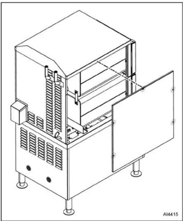
LEFT SIDE TOP PANEL
WARNING
Disconnect the electrical power to the machine and follow lockout / tagout procedures.
- Remove five screws from locations noted in Fig. 3.
natural_image
Technical line drawing of a mechanical oven or chamber unit with cooling fins and mounting feet (no text or symbols)Fig. 3
- Pull out bottom of panel and slide down out of top cover.
- Reverse procedure to install.
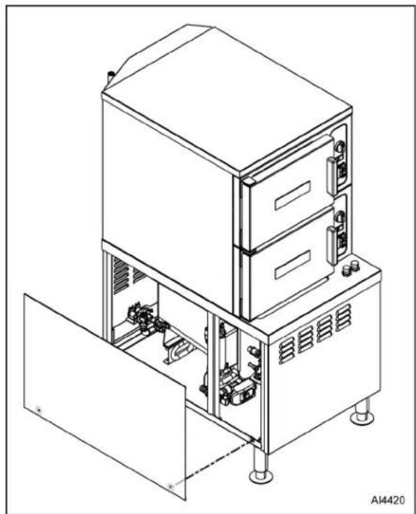
LEFT SIDE BOTTOM PANEL

WARNING
Disconnect the electrical power to the machine and follow lockout / tagout procedures.
- Remove two screws from locations noted in Fig. 4.
natural_image
Technical line drawing of an industrial machine with control panel and storage unit (no text or symbols)Fig. 4
- Pull out bottom of panel and slide down out of frame.
- Reverse procedure to install.
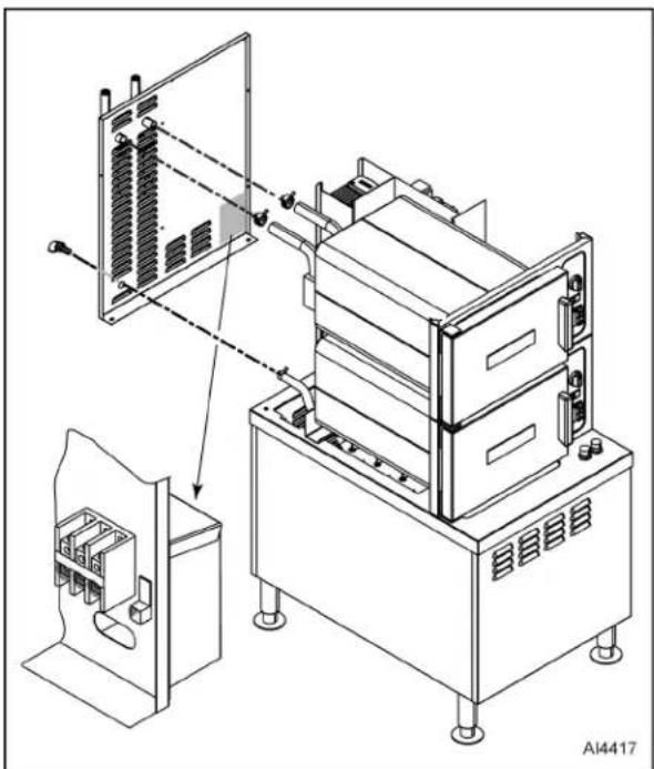
TOP REAR PANEL

WARNING
Disconnect the electrical power to the machine and follow lockout / tagout procedures.
- Remove RIGHT SIDE TOP PANEL and LEFT SIDE TOP PANEL.
- If desired, remove TOP COVER.
- LWE Models Only: Compress hose fittings and remove hoses from LWE vents.
natural_image
Technical line drawing of an electrical cabinet with internal components and wiring, showing assembly and mounting details (no text or symbols)Fig. 5
- Compress hose fitting and remove hose from rear vent fitting.
- Remove facility power cable wires from input terminal and ground block.
NOTE: Wires can be left connected to terminal block as long as top rear panel is supported and no strain is placed on the electrical leads.
- Remove four screws as noted in Fig. 6

natural_image
Technical line drawing of an electrical enclosure with internal components and mounting base (no text or symbols)Fig. 6
NOTICE
Do not reuse hose clamps. Always replace opened / removed hose clamps with new ones.
- Reverse procedure to install.
BOTTOM REAR PANEL

WARNING
Disconnect the electrical power to the machine and follow lockout / tagout procedures.
- Remove five screws from locations noted in Fig. 7.

natural_image
Technical line drawing of an industrial machine with cooling unit and fan (no text or symbols)Fig. 7
- Pull out bottom of panel and slide down out of frame.
- Reverse procedure to install.
BOTTOM FRONT PANEL

WARNING
Disconnect the electrical power to the machine and follow lockout / tagout procedures.
- Remove two screws from locations noted in Fig. 8.

natural_image
Line drawing of a multi-tiered industrial machine with open door and internal components (no text or symbols)Fig. 8
- Pull out bottom of panel and slide down out of frame.
- Reverse procedure to install.
TOP COVER

WARNING
Disconnect the electrical power to the machine and follow lockout / tagout procedures.
- Remove five screws from locations noted in Fig. 9.

natural_image
Technical line drawing of an electronic device with internal components and a close-up view of the next panel (no text or symbols)Fig. 9
- Lift cover off steamer unit.
- Reverse procedure to install.
DOOR
WARNING
Disconnect the electrical power to the machine and follow lockout / tagout procedures.
- Close door.
- Remove LEFT SIDE TOP PANEL.
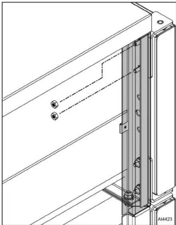
- Remove nuts (Fig. 10) from upper hinge located inside front panel.
natural_image
Technical line drawing of a mechanical assembly with mounting brackets and a vertical rail (no text or symbols)Fig. 10
- Open door slightly and pull upper hinge up and out of upper door hinge bushing.
- Lift door assembly (Fig. 11) up and off lower door hinge.
- Reverse procedure to install.
- Check door for fit and proper sealing of gasket.

natural_image
Technical line drawing of a cabinet or enclosure assembly with mounting brackets and structural details (no text or symbols)Fig. 11
DOOR GASKET
WARNING
Disconnect the electrical power to the machine and follow lockout / tagout procedures.
- Open door.
- Remove shoulder screws, gasket door guard (1, Fig. 12), and gasket door retainer (2) from door assembly (4).
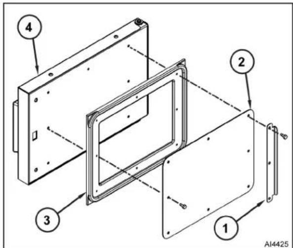
Fig. 12
-
Remove gasket (3) from inner door panel.
-
Remove RTV from inner door panel.
NOTE: Reapply RTV 109 to portion of inner door panel where it was removed in Step 4.
NOTE: Place a small amount of RTV109 into inner door panel gasket screw holes before assembly.
- Reverse procedure to install.
DOOR HANDLE

WARNING
Disconnect the electrical power to the machine and follow lockout / tagout procedures.
Removal
- Open door.
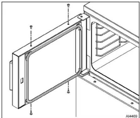
- Remove four screws from locations noted in Fig. 13.
natural_image
Technical line drawing of a mechanical assembly with mounting brackets and structural elements (no text or symbols)Fig. 13
- Pull outer door housing (Fig. 14) away from inner door panel starting at hinge side of door to separate door halves.

natural_image
Technical line drawing of a mechanical assembly with no visible text or symbolsFig. 14
4. Remove lock nuts, stepped spacers (3, Fig. 15) and door handle (1) from door.

Fig. 15
NOTE: Smaller radius of step spacers fit into outer door housing slots and is used to provide clearance for handle operation.
NOTE: Apply Lubriplate 630AA (2, Fig. 15) around slots of outer door housing where step spacers contact housing.
NOTE: Make sure door handle arrow points up.
NOTE: Apply Loctite 242 to screw threads.
5. Reverse procedure to install.
DOOR LATCH

WARNING
Disconnect the electrical power to the machine and follow lockout / tagout procedures.
-
Separate inner and outer door housing assembly. Refer to DOOR HANDLE.
-
Remove screws and latch mechanism (Fig. 16).

natural_image
Technical line drawing of a metal frame assembly with mounting holes and bolted joints (no text or symbols)Fig. 16
- Remove E-clip (Fig. 17) from latch assembly pins and pull pins from latch mechanism.
- Remove retaining pin from spring pin.
- Separate sliding bracket from stationary bracket.

natural_image
Technical line drawing of a mechanical assembly with two views: one showing internal components and the other showing a spring-loaded housing (no text or symbols present)Fig. 17
NOTE: Apply Lubriplate 630AA (1, Fig. 17) to sides of sliding bracket.
NOTE: Install pins so heads face inward toward hinge side of inner door panel.
NOTE: Apply Loctite 271 to threads of screws before assembly and secure latch assembly to inner door panel.
- Reverse procedure to install.
HINGE BEARINGS

WARNING
Disconnect the electrical power to the machine and follow lockout / tagout procedures.
- Close door.
- Remove LEFT SIDE TOP PANEL.
- Remove DOOR.
- Pry top (1, Fig. 18) and bottom (2) hinge bearings from door assembly.
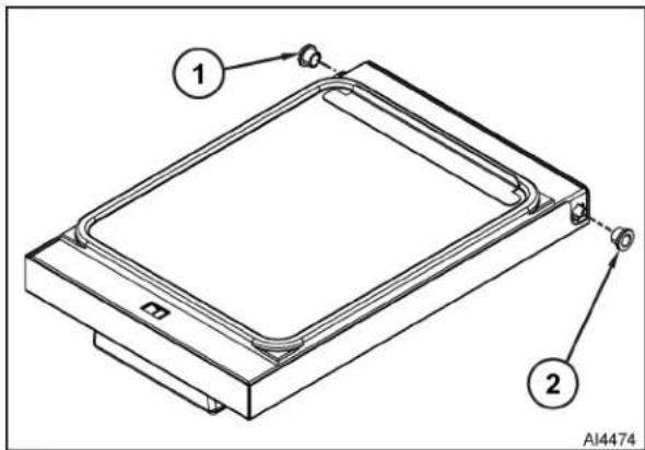
NOTE: Do not drive bearing into place or door panel could be damaged. Press bearing into position.
NOTE: When replacing door hinge bearings, replace both hinge bearings.
- Reverse procedure to install.
DRAIN BOX
WARNING
Disconnect the electrical power to the machine and follow lockout / tagout procedures.
- Turn off machine to drain steam generator tank. Allow steamer to complete drain cycle.
- Turn off water supply.
- Remove RIGHT SIDE BOTTOM PANEL.
- Disconnect drain plumbing from drain box outlet fitting.
NOTE: Document wire connections.
-
Disconnect condensate thermostat wires.
-
Disconnect following hoses:
- Cold water condensate hoses (2 and 6, Fig. 19).

Fig. 19
• Cooking compartment drain hoses (3 and 4).
- Steam generator drain hoses (1 and 7).
• Pressure relief hose (5).
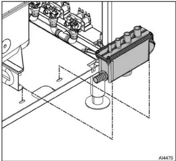
- Remove two screws and drain box (Fig. 20).
natural_image
Technical line drawing of a mechanical assembly with mounting holes and a central component (no text or symbols)Fig. 20
NOTE: Retain condensate thermostat for use on replacement drain box.
- Remove condensate thermostat (Fig. 21) from drain box.

natural_image
Technical line drawing of an electrical component with connectors and a dashed line indicating a connection (no text or symbols present)Fig. 21
NOTICE
Do not reuse hose clamps. Always replace opened / removed hose clamps with new ones.
NOTE: Apply thread sealant to condensate thermostat threads.
- Reverse procedure to install.
CONDENSATE THERMOSTAT
WARNING
Disconnect the electrical power to the machine and follow lockout / tagout procedures.
- Allow steamer to complete drain cycle.
- Turn off water supply.
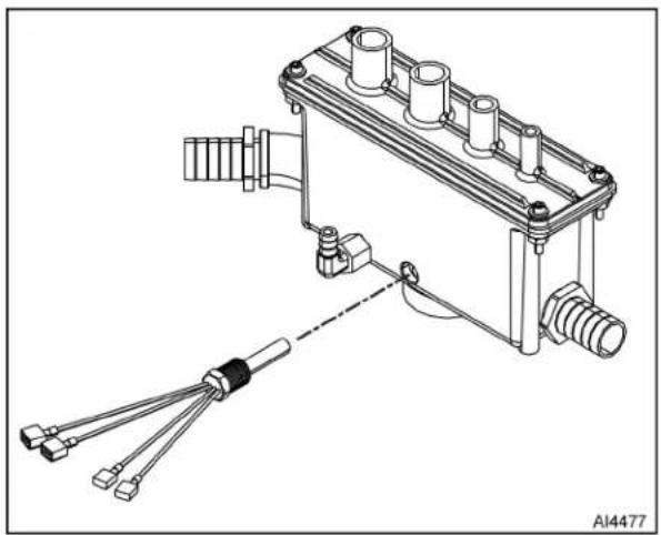
- Unthread condensate thermostat (Fig. 22) from drain box.
AI4476
natural_image
Technical line drawing of an electrical component with connectors and wiring (no text or symbols)Fig. 22
NOTICE
Do not reuse hose clamps. Always replace opened / removed hose clamps with new ones.
NOTE: Apply thread sealant to condensate thermostat threads.
- Reverse procedure to install.
HEATING ELEMENT

WARNING
Disconnect the electrical power to the machine and follow lockout / tagout procedures.
- Turn off machine to drain steam generator tank. Allow steamer to complete drain cycle.
- Turn off water supply.
NOTE: Remove left panel for upper compartment steam generator, right panel for lower compartment steam generator.
- Remove following covers and panels:
• RIGHT SIDE TOP PANEL
• BOTTOM FRONT PANEL
• RIGHT SIDE BOTTOM PANEL
or
LEFT SIDE BOTTOM PANEL
NOTE: Document wire connections.
- Disconnect heating element lead wires from limiting contactor (1A or 2A) Fig. 23 and regulating contactor (1B or 2B).
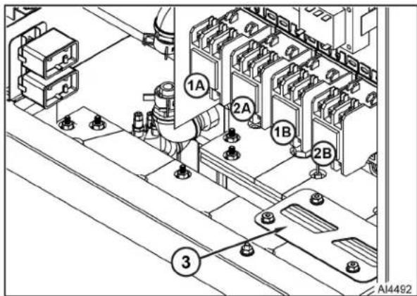
Fig. 23
- Remove four nuts, washers, and bracket (3) from both steam generators.
- Right steam generator only:
NOTE: Right steam generator must be moved to provide clearance.
A. Disconnect steam hose (1, Fig. 24) from generator tank.
B. Disconnect drain hose (2) from drain box.
C. Loosen / remove bolts and washers (3) that secure steam generator to mounting brackets.
D. Move steam generator forward off mounting brackets.
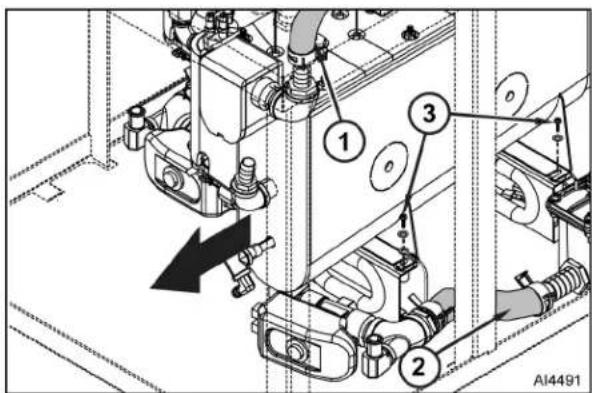
Fig. 24
- Position high-limit thermostat (1, Fig. 25) capillary tube to facilitate heating element removal. Avoid creating sharp bends or kinks in the capillary tube.
- Remove nut, lock washers, and flat washers that secure heating element (2) to tank (4).
- Pull heating element out of steam generator tank.
NOTE: Note mounting position of high-limit bulb.
- Remove high-limit bulb from heating element.

Fig. 25
- Remove high-limit capillary tube compression fitting then remove high-limit capillary tube and bulb from heating element.
- Remove gasket (3) from steam generator tank.
- Clean remaining sealant from top lip of steam generator tank.
NOTICE
Do not reuse hose clamps. Always replace opened / removed hose clamps with new ones.
NOTE: Position capillary bulb so it is centered across heating elements.
NOTE: Apply pipe thread sealant to threads of large capillary tube mounting nut before installing.
NOTE: Pull excess capillary tubing out of heating element. Route capillary tube such that there are no sharp bends or kinks.
NOTE: Right steam generator - make sure ground bond strap is properly installed.
NOTE: Install a new gasket when reassembling steam generator tank. Temporarily secure gasket in place with RTV 109.
NOTE: Tighten heating element screws evenly to 70 in-lbs. Follow tightening sequence pattern as shown in Fig. 26.
- Reverse procedure to install.
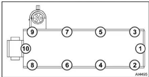
flowchart
graph TD
    A["Top Node"] --> B["Node 9"]
    B --> C["Node 7"]
    C --> D["Node 5"]
    D --> E["Node 3"]
    E --> F["Node 1"]
    F --> G["Node 2"]
    G --> H["Node 4"]
    H --> I["Node 6"]
    I --> J["Node 8"]
    J --> K["Node 10"]
Fig. 26
STEAM GENERATOR TANK

WARNING
Disconnect the electrical power to the machine and follow lockout / tagout procedures.
NOTE: Replace any defective components when disassembling / replacing steam generator tank.
- Turn off machine to drain steam generator tank. Allow steamer to complete drain cycle.
- Turn off water supply.
NOTE: Remove left panel for upper compartment steam generator, right panel for lower compartment steam generator.
- Remove following covers and panels:
• BOTTOM FRONT PANEL
• LEFT SIDE BOTTOM PANEL
or
• RIGHT SIDE BOTTOM PANEL
- Remove four nuts, washers, and bracket (1, Fig. 27) from both steam generators.

Fig. 27
-
Disconnect following hoses:
-
Delime hose (2A or 2B).
- Steam hose (3A or 3B).
- Motorized valve drain hose (4A or 4B).
- Flush hose (5A or 5B).
-
Fast and slow supply hoses (6A or 6B).
-
Disconnect heating element leads from limiting (1A or 1B, Fig. 28) and regulating contactors (2A or 2B).

Fig. 28
- Remove high limit switch (3A or 3B) from mounting bracket.
NOTE: Document all wire / lead connections
- Disconnect following electrical wires and cables:
• High pressure limit switch (1A or 1B) leads.
• Water level probe (2A or 2B) leads.
- Motorized drain valve (3A or 3B) leads.
- Hold thermostat (4A or 4B) leads.
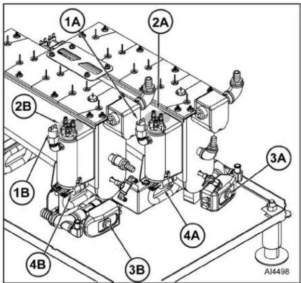
Fig. 29
-
Remove two bolts, washers, and steam generator tank.
-
Remove HEATING ELEMENT.
-
Remove following items from steam generator tank:
• Water level probes (1, Fig. 30).
- Steam outlet fitting (2).
- Delime port fitting (3).
• Supply port fitting (4).
- Motorized drain valve assembly (5).
- Hold thermostat (6).
- Nipple and cap (7).
• High pressure limit switch (8).
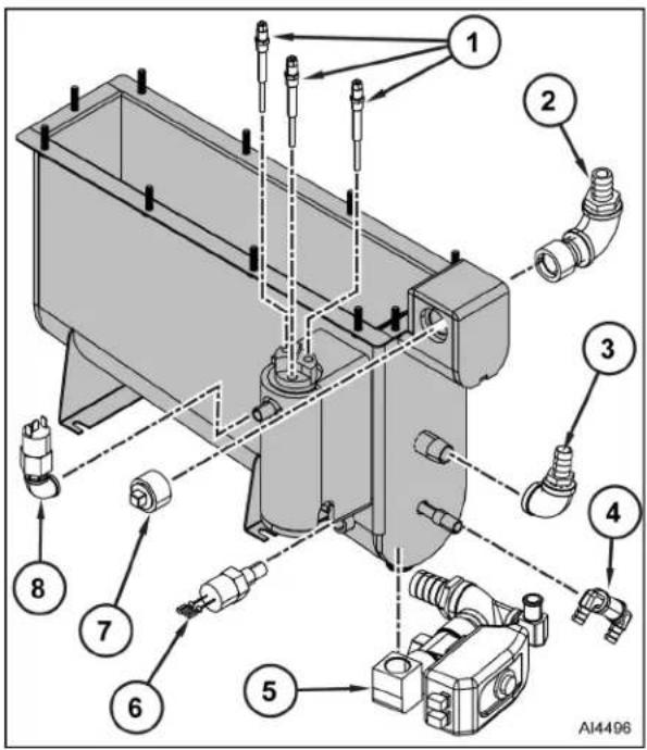
Fig. 30
- Remove gasket from steam generator tank.
NOTICE
Do not reuse hose clamps. Always replace opened / removed hose clamps with new ones.
NOTE: Temporarily secure gasket in place with RTV 109.
NOTE: Use high temperature aluminum foil tape to secure insulation.
NOTE: Apply thread sealant to all pipe threads connected to steam generator tank.
NOTE: Follow torque requirement / tightening sequence shown in HEATING ELEMENT.
- Reverse procedure to install.
MOTORIZED DRAIN VALVE (PROFESSIONAL)
WARNING
Disconnect the electrical power to the machine and follow lockout / tagout procedures.
NOTE: There are two generations of motorized drain valves on ET models. Shown below are 1st Generation (1, Fig. 31), 2nd Generation (2, Fig. 31).

natural_image
Two industrial control devices, one with a dial and labeled component, the other with a display and control buttons (no visible text or symbols on the devices themselves)Fig. 31
- Turn steamer off by using on/off switch on front panel of steamer.
A. Allow steamer to complete drain cycle.
B. If motorized drain valve has malfunctioned such that tank will not drain normally, refer to Drain Tank Manually for draining procedure.
Drain Tank Manually
- Turn off water supply to steamer.
- Disconnect power to steamer, allow enough time for water in steam generator tank to cool to 140° F before attempting to manually open drain valve.
- Remove BOTTOM FRONT PANEL.
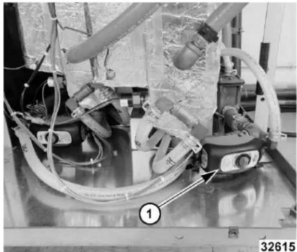
- Locate the motorized drain valve (1, Fig. 32) found at lower right side of steam generator tank.
natural_image
Industrial robotic arm with hoses and control panel, no visible text or symbolsFig. 32
- Perform valve manual override.
1st GENERATION
A. Push in and turn knob 90° counterclockwise to open (Fig. 33).

Fig. 33
B. Return manual drain override knob to the closed position (Fig. 34) 90° clockwise (slot in horizontal position).

Fig. 34
2nd GENERATION
A. Pull knob (1, Fig. 35) out and turn while watching indicator window. Verify red line inside indicator window (2, Fig. 35) is vertical (closed position) with valve body.

Fig. 35
B. Pull knob (1, Fig. 36) out and turn while watching indicator window. Verify red line inside indicator window (2, Fig. 36) is horizontal (open position) with valve body.

Fig. 36
Removal
- Turn off water supply to steamer.
- Remove BOTTOM FRONT PANEL.
- Remove the motorized control assembly.
1st GENERATION
- Press and hold spring catch (1, Fig. 37) then life motorized control assembly (2, Fig. 37) off valve body (3, Fig. 37).
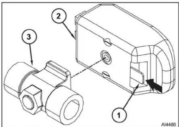
Fig. 37
2nd GENERATION
- Remove 2.5mm screws (Fig. 38).

natural_image
Close-up of a mechanical valve assembly with attached components and wiring (no visible text or symbols)Fig. 38
NOTE: 1st generation has an electrical plug and 2nd generation is hard wired. If electrical wiring is not connected correctly, the motorized drain valve will not function.
- Note location of electrical connections then disconnect electrical wiring from motorized control assembly.
- Disconnect the drain and drain flush hoses from the Tee located below the drain valve.
-
Remove drain valve body from steam generator tank.
-
Separate tee and nipple from the drain valve body.
- Reassemble parts removed in reverse order. Apply liquid pipe thread sealant to threads of plumbing connections.
NOTE: If motorized drain valve is in the open position when power is applied to the steamer with the power switch on, drain valve will not close and fill water will flow through the generator into the drain.
- Verify On/Off switch is in off position and motorized drain valve is closed before applying power to steamer.
NOTE: When power is applied and power switch is off steamer will enter a drain cycle.
- Check steamer for proper operation and leaks around drain valve.
SUPER-HEATER ELEMENT
NOTE: Super-heaters are installed only on Professional models.
- Turn off machine to drain steam generator tank. Allow steamer to complete drain cycle.
- Turn off water supply.
- Remove the following covers and panels.
• RIGHT SIDE TOP PANEL
• RIGHT SIDE BOTTOM PANEL
• BOTTOM FRONT PANEL
NOTE: Document wire connections.
- Remove super-heater electrical wires from electrical panel.
- Remove cable ties that secure super-heater electrical wires in place.
- Remove / peel back insulation from super-heater head.
- Remove super-heater element from pipe (Fig. 39).

natural_image
Technical line drawing of a mechanical assembly with pipes, valves, and components (no text or symbols)Fig. 39
NOTICE
Do not reuse hose clamps. Always replace opened / removed hose clamps with new ones.
NOTE: Apply pipe thread sealant to threads of superheater element before assembly.
NOTE: Tape insulation around head of super-heater element using high-temperature aluminum foil tape.
NOTE: Make sure insulated piping assembly is horizontal or super-heater element head end of assembly is slightly elevated.
- Reverse procedure to install.
HOLD THERMOSTAT

WARNING
Disconnect the electrical power to the machine and follow lockout / tagout procedures.
- Turn off machine to drain steam generator tank. Allow steamer to complete drain cycle.
- Remove BOTTOM FRONT PANEL.
NOTE: Document wire connections.
- Disconnect electrical lead wires from hold thermostat.
- Remove hold thermostat from steam generator tank.

natural_image
Technical line drawing of a mechanical assembly with no visible text or symbolsFig. 40
NOTE: Apply Loctite 565 to hold thermostat threads before installing.
- Reverse procedure to install.
HIGH LIMIT THERMOSTAT
WARNING
Disconnect the electrical power to the machine and follow lockout / tagout procedures.
- Turn off machine to drain steam generator tank. Allow steamer to complete drain cycle.
- Turn off water supply.
NOTE: High limit thermostat bulb and capillary tube are removed from heating element in HEATING ELEMENT procedure.
- Remove HEATING ELEMENT.
NOTE: Document wire connections.
- Disconnect electrical wiring from high-limit thermostat (1 or 2, Fig. 41).

Fig. 41
- Remove high-limit thermostat from mounting bracket.
- Reverse procedure to install.
WATER LEVEL PROBES

WARNING
Disconnect the electrical power to the machine and follow lockout / tagout procedures.
NOTE: Remove left panel for upper compartment steam generator, front panel for lower compartment steam generator.
- Remove LEFT SIDE BOTTOM PANEL or BOTTOM FRONT PANEL.
NOTE: Document wire connections. - Remove nut(s) and lead(s) from probe(s).
- Remove water level probe(s)
• High Level (1, Fig. 42).
- Low Level (2) and / or
- Low Level Cut Off (3).

Fig. 42
NOTICE
Do not use anything abrasive on insulators.
4. Use a soft cloth to remove all accumulated deposits from probe insulator.
NOTE: If probes are dirty, delime steam generator tank after assembling.
NOTE: Apply pipe sealant to probe threads
5. Reverse procedure to install.
| WATER LEVEL PROBE ELECTRICAL CONNECTIONS | |||
| Item Number | Water Level Controller | Wiring | Water Level Probe |
| 1 H #5A | HL - High Level Probe | ||
| 2 L #6B | LL - Low Level Probe | ||
| 3 LLCO #7C | LLCO - Low Level Cut Off | ||
| 4 G #8 Ground | |||
SENSOR PROBE

WARNING
Disconnect the electrical power to the machine and follow lockout / tagout procedures.
NOTE: Sensor probes are installed only on LWE models.
- Remove TOP REAR PANEL.
NOTE: Document wire connections.
F45636 Rev. A (0821) Page 26 of 68
- Disconnect sensor probe (1, Fig. 43 wires from PID controller (2) leads.
- Remove sensor probe (1) from sensor tube.
- Reverse procedure to install.

Fig. 43
UPPER COOKING COMPARTMENT
WARNING
Disconnect the electrical power to the machine and follow lockout / tagout procedures.
NOTE: Cooking compartment and front panel are constructed as an assembly and cannot be separated.
- Turn off machine to drain steam generator tank. Allow steamer to complete drain cycle.
- Turn off water supply.
- Remove following covers and panel.
• RIGHT SIDE TOP PANEL
• LEFT SIDE TOP PANEL
- TOP COVER
• TOP REAR PANEL
NOTE: Remove cabinet door actuator bracket and buzzer as an assembly. No further disassembly required.
NOTE: Document all wire connections.
-
Remove following components:
-
DOOR
- TIMER
• INDICATOR LIGHT ASSEMBLY - ON/OFF SWITCH
- BUZZER
- Remove bolts (4, Fig. 44) and nuts that secure cooking compartment front panel to lower cooking compartment.
- Remove lower hinge (3) from front panel.
- Remove vacuum breaker (2).
- Disconnect steam hose from cooking compartment steam port inlet fitting.
NOTE: Retain steam port inlet fitting for reuse.
- Remove steam port inlet fitting (1).

Fig. 44
- Basic and Professional Models: Disconnect compartment drain hose from rear of cooking compartment.
- LWE Models:
A. Remove SENSOR PROBE.
B. Remove sensor probe fitting (1, Fig. 45) from vent weldment (5).
C. Remove vent hose (4) from vent weldment (5).
- Remove cable clamp and drain hose from bottom of vent weldment (5).
- Remove mounting nuts that secure cooking compartment (2) to vertical mounting brackets (3).
- Remove cooking compartment assembly from steamer.
- Remove vent weldment (5) cooking compartment (2).

Fig. 45
NOTICE
Do not reuse hose clamps. Always replace opened / removed hose clamps with new ones.
NOTE: Perform DOOR LATCH ADJUSTMENT.
- Reverse procedure to install.
LOWER COOKING COMPARTMENT
WARNING
Disconnect the electrical power to the machine and follow lockout / tagout procedures.
NOTE: Cooking compartment and front panel are constructed as an assembly and cannot be separated.
- Turn off machine to drain steam generator tank. Allow steamer to complete drain cycle.
- Turn off water supply.
- Remove following covers and panels.
• RIGHT SIDE TOP PANEL
• LEFT SIDE TOP PANEL
- TOP COVER.
• TOP REAR PANEL
• BOTTOM FRONT PANEL
- Remove upper cooking compartment as follows:
A. Note connections and disconnect following components from wire harnesses:
- Timer
- ON/OFF Switch
-
Indicator Lights
-
Buzzer
- Door Switch
B. Remove four bolts nuts (1, Fig. 46) that secure upper and lower cooking compartment front panels.
C. Disconnect steam supply hose (2) from steam fitting.
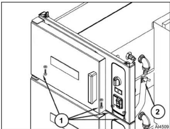
Fig. 46
D. Remove SENSOR PROBE.
E. Disconnect drain hose from vent weldment.
F. Remove nuts that secure upper cooking compartment (1, Fig. 47) to vertical brackets (2).
G. Remove upper cooking compartment from steamer.

Fig. 47
NOTE: Remove cabinet door actuator bracket and buzzer as an assembly. No further disassembly required.
NOTE: Document all wire connections.
-
Remove following components:
-
DOOR
- TIMER
• INDICATOR LIGHT ASSEMBLY
• ON/OFF SWITCH -
BUZZER
-
Remove lower hinge (3, Fig. 48) from front panel.
-
Remove bolts / nuts (4) and screws (5) that secure cooking compartment front panel to frame.
- Remove vacuum breaker (2).
- Disconnect steam hose from cooking compartment steam port inlet fitting.
- Remove steam port inlet fitting (1).

Fig. 48
- Basic and Professional Models: Disconnect compartment drain hose from rear of cooking compartment.
- LWE Models:
A. Remove SENSOR PROBE.
B. Remove vent hose (1, Fig. 49) from vent weldment (2).
C. Remove drain hose (3) from bottom of vent weldment (2).
- Remove nuts that secure cooking compartment to cross frame (4).
- Remove nuts that secure cooking compartment to bracket (5).
- Remove cooking compartment assembly from steamer.

Fig. 49
- LWE Models Only:
A. Remove sensor probe fitting (1, Fig. 50) from vent weldment (2).
B. Remove vent weldment (2) cooking compartment (3).
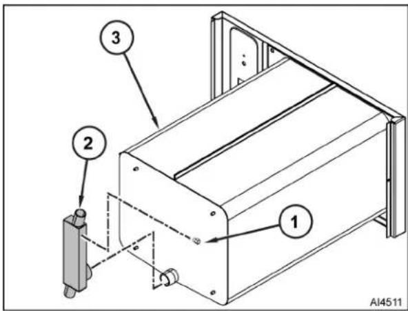
Fig. 50
NOTICE
Do not reuse hose clamps. Always replace opened / removed hose clamps with new ones.
NOTE: Perform DOOR LATCH ADJUSTMENT.
- Reverse procedure to install.
PRESSURE SWITCH
WARNING
Disconnect the electrical power to the machine and follow lockout / tagout procedures.
- Turn off machine to drain steam generator tank. Allow steamer to complete drain cycle.
- Turn off water supply.
- Remove LEFT SIDE BOTTOM PANEL and BOTTOM FRONT PANEL.
NOTE: Document wire connections.
- Disconnect electrical wiring from pressure switch.
- Remove pressure switch (Fig. 51) from piping.

natural_image
Technical line drawing of a mechanical assembly with no visible text or symbolsFig. 51
NOTE: Apply pipe thread sealant to pressure switch threads.
NOTE: Replacement component is an adjustable pressure switch (Fig. 52).
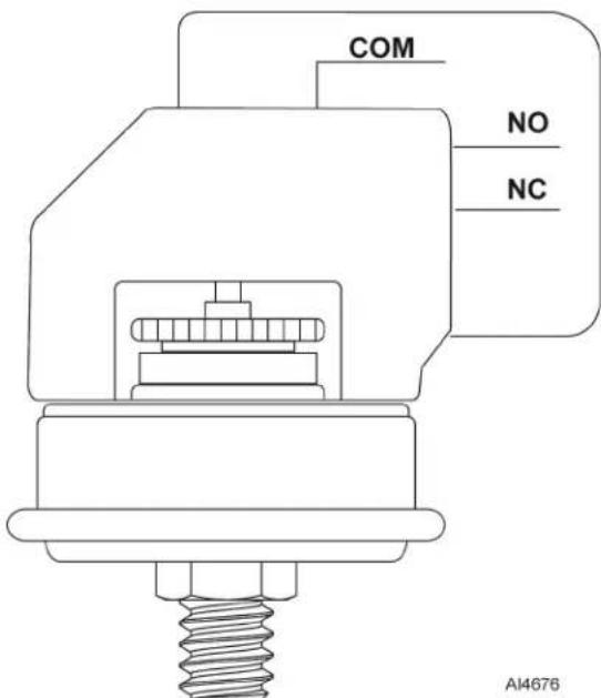
Fig. 52
- Reverse procedure to install.
- Perform PRESSURE SWITCH CHECK / ADJUST.
VACUUM RELIEF VALVE

WARNING
Disconnect the electrical power to the machine and follow lockout / tagout procedures.
- Turn off machine to drain steam generator tank. Allow steamer to complete drain cycle.
- Turn off water supply.
- Remove LEFT SIDE BOTTOM PANEL.
NOTE: Document wire connections.
- Disconnect electrical wiring from vacuum relief valve.
- Remove hose clamp (Fig. 53) and hose from vacuum relief valve elbow.

natural_image
Technical line drawing of a mechanical assembly with pipes, valves, and a central component (no text or symbols)Fig. 53
- Unthread vacuum relief valve from piping.
- Unthread elbow fitting from vacuum relief valve.
NOTE: Apply pipe sealant to all pipe threads.
- Reverse procedure to install.
FILL VALVES

WARNING
Disconnect the electrical power to the machine and follow lockout / tagout procedures.
NOTICE
Unfiltered and filtered valve assemblies have different flow rates and must not be interchanged.
NOTE: Filtered and non-filtered water solenoid valves are constructed as dual water valve assemblies. To differentiate between fast and slow fill outlets, hold dual water valve assembly with inlet up and outlets facing forward. Fast flow outlet is on left and slow flow outlet is on right.
- Turn off machine to drain steam generator tank. Allow steamer to complete drain cycle.
- Turn off water supply.
- Disconnect incoming filtered water hose to machine.
- Disconnect incoming unfiltered water hose to machine.
- Remove BOTTOM REAR PANEL.
NOTE: Document wire connections.
- Disconnect valve wires.
- Disconnect hoses from solenoid valve (Fig. 54).
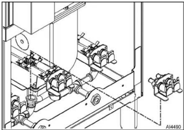
natural_image
Technical line drawing of industrial piping and valve assembly (no text or symbols)Fig. 54
- Unthread solenoid valve.
NOTICE
Do not reuse hose clamps. Always replace opened / removed hose clamps with new ones.
- Reverse procedure to install.
ELECTRONIC COMPONENT

WARNING
Disconnect the electrical power to the machine and follow lockout / tagout procedures.
NOTICE
Certain components in this system are subject to damage by electrostatic discharge (ESD) during field repairs. An ESD kit is required to prevent damage. The ESD kit must be used anytime the circuit board is handled.
NOTE: This procedure should be used for replacement of electrical / electronic components. Refer to COMPONENT LOCATION for location information.
- Remove RIGHT SIDE TOP PANEL.
NOTE: Document wire connections.
-
Disconnect wires from component to be replaced.
-
Remove fasteners and component.
-
Reverse procedure to install.
PID CONTROLLER
WARNING
Disconnect the electrical power to the machine and follow lockout / tagout procedures.
NOTE: PID controllers are installed only on LWE models.
- Remove RIGHT SIDE TOP PANEL.
- Remove screws and PID mounting bracket (1, Fig. 55) from electrical panel

Fig. 55
NOTE: Document connection locations.
- Remove two electrical plugs (2) from rear of PID controller (3).
-
Pull PID mounting bracket away from electrical panel to access PID controller.
-
Remove PID controller:
NOTE: Use a 1.5" putty knife or equivalent thin tool underneath each locking tab (2, Fig. 56) to hold teeth away from ridges.
- Slide mounting collar away from mounting bracket.
- Slide mounting collar off PID controller (1).
- Remove PID controller from panel.

Fig. 56
NOTE: Insert PID controller into panel opening, slide mounting collar over controller, and push it up against mounting bracket to engage locking tabs.
-
Reverse procedure to install.
-
Perform PID CONTROLLER TEST - LWE MODEL.
SOLID STATE CONTACTOR
WARNING
Disconnect the electrical power to the machine and follow lockout / tagout procedures.
NOTE: Solid state contactors are installed only on LWE models.
- Remove RIGHT SIDE TOP PANEL.
- Remove two screws and internal panel (1, Fig. 57).

Fig. 57
NOTE: Document wire connections.
F45636 Rev. A (0821) Page 32 of 68
- Disconnect wires from solid state contactor (2).
- Remove four screws and solid state contactor from mounting plate.
- Reverse procedure to install.
ON/OFF SWITCH

WARNING
Disconnect the electrical power to the machine and follow lockout / tagout procedures.
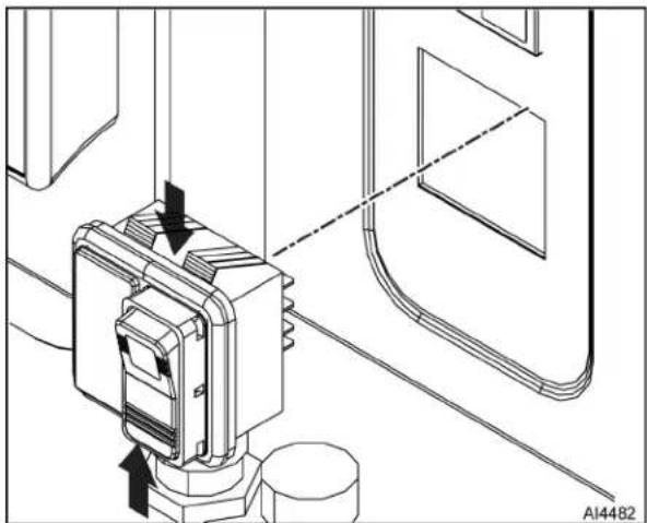
- Remove RIGHT SIDE TOP PANEL.
- Disconnect electrical plug from on/off switch.
- Remove on/off switch (Fig. 58) from front panel.
natural_image
Technical line drawing of a mechanical component with directional arrows indicating motion (no text or symbols)Fig. 58
- Reverse procedure to install.
INDICATOR LIGHT ASSEMBLY

WARNING
Disconnect the electrical power to the machine and follow lockout / tagout procedures.
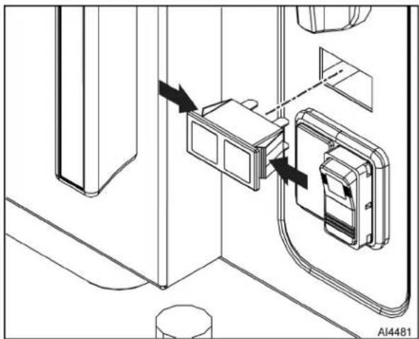
- Remove RIGHT SIDE TOP PANEL.
- Disconnect electrical plug from indicator light assembly.
- Remove indicator light assembly (Fig. 59) from front panel.
natural_image
Technical line drawing of a mechanical or electrical component with arrows indicating assembly or connection (no text or symbols present)Fig. 59
- Reverse procedure to install.
DOOR SWITCH

WARNING
Disconnect the electrical power to the machine and follow lockout / tagout procedures.
- Remove RIGHT SIDE TOP PANEL.
- Open cooking compartment door.
NOTE: Document wire connections. - Disconnect wiring from switch (1, Fig. 60).

Fig. 60
- Remove switch from door switch mounting bracket. Retain hardware.
NOTE: Verify E-clip (2) is installed on door switch linkage in groove nearest front panel (if two grooves in linkage are present).
NOTE: Position switch as far forward as possible then tighten two screws.
- Reverse procedure to install.
TIMER
WARNING
Disconnect the electrical power to the machine and follow lockout / tagout procedures.
NOTE: When timer reaches zero, an external buzzer will sound and steam will stop entering cooking compartment. The steamer has extra components to utilize the constant steam setting allowing the steamer to operate continuously.
- Remove RIGHT SIDE TOP PANEL.
NOTE: Document wire connections. - Disconnect timer wires.
- Pull knob (Fig. 61) from timer shaft.

natural_image
Technical line drawing of a mechanical assembly with no visible text or symbolsFig. 61
NOTE: Inspect rotary shaft seal. Replace if damaged, worn or signs of moisture migration into control area around timer shaft is evident.
- Remove rotary shaft seal from timer shaft
- Remove nut and timer from front panel.
NOTE: Apply a small amount of Petrogel under rotary shaft seal.
6. Reverse procedure to install.
BUZZER
- Remove RIGHT SIDE TOP PANEL.
NOTE: Document wire connections
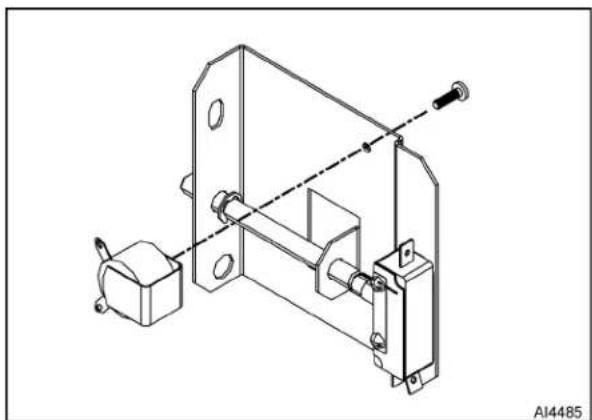
- Disconnect electrical wiring from the buzzer and door switch.
- Remove nut, washer, and door striker (Fig. 62).

natural_image
Technical line drawing of a mechanical assembly with no visible text or symbolsFig. 62
- Remove nut and cabinet door actuator bracket.
- Remove fastener and buzzer from cabinet door actuator bracket (Fig. 63).
natural_image
Technical line drawing of a mechanical assembly with mounting bracket and mounting base (no text or symbols)Fig. 63
- Reverse procedure to install.
SERVICE PROCEDURES AND ADJUSTMENTS
DOOR LATCH ADJUSTMENT
NOTICE
Should steamer door jam and cannot be opened, DO NOT FORCE OR PRY door as damage will occur.
JAMMED DOOR
- Lift up on bottom of door at handle end to disengage latch.
A. If door does not open, remove RIGHT SIDE TOP PANEL.
NOTE: Loosening nut should release striker from latch.
B. Locate striker and loosen / remove nut.
C. Open door.
- Remove striker.
- Remove any burrs on striker that may cause latch to stick.
- Reinstall striker with slotted side up.
- Snug striker nut.
- Apply Loctite 271 to striker threads.
- Perform DOOR LATCH ADJUSTMENT.
Door Adjustment
- Reinstall striker with slot pointing upward and hand tighten nut only.
- Close door to center striker in front panel mounting hole.
- Open door and check striker slot for horizontal alignment. The slot on striker must be kept horizontal in order for door latch to catch properly and latch.
NOTE: Do not over-tighten nut. If over-tightened, striker may turn and change alignment.
NOTE: If door does not open easily, add shims between striker and cabinet front. When adding shims make certain that door gasket seals properly and steamer does not leak. Remove shims as necessary until leaking stops.
4. Once proper slot alignment has been set, hold striker close to its base then tighten the striker nut. Be careful not to damage striker slot when tightening or door may not latch properly.
HEATING ELEMENT DIAGNOSTIC CHECK - LWE MODELS
WARNING
Certain procedures in this section require electrical test or measurements while power is applied to the machine. Exercise extreme caution at all times and follow Arc Flash procedures. If test points are not easily accessible, disconnect power and follow Lockout/Tagout procedures, attach test equipment and reapply power to test.
- Check voltage across heating element wires at limiting (1/4CON) and regulating (2/5CON) contactor load terminals and verify against data plate voltage as outlined in steps below. See WIRING DIAGRAMS for connections.
A. Voltage should be measured after PID controller has energized solid state contactor (3/6CON) during initial heat up (longest ON time); or during temperature recovery after door has been opened to allow cooking compartment to cool down then closed (timer must be on).
B. When temperature in the sensor tube (vent) reaches approximately 180° F, the PID controller will signal the solid state contactor (3/6CON) to begin pulsing power to the heating elements to reduce energy use. If voltage is measured during the pulsing state, the meter readings will not be steady for a good reading.
- If voltage is correct, check current draw Step 3. If voltage is not correct, check:
A. Voltage supply to steamer at terminal block.
B. Fuses or breakers blown.
C. Power to contactor coils (limiting 1/4CON) (regulating 2/5CON).
D. Limiting (1/4CON) or regulating (2/5CON) contactors not pulling in (mechanical failure).
E. Solid state contactor (3/6CON) not energized by PID controller to provide power to the load contacts on regulating contactor (2/5CON).
1) Perform PID CONTROLLER TEST - LWE MODEL.
2) Check control signal wiring between PID controller and solid state contactor (3/6CON);
3) Check ground wire is connected to solid state contactor (3/6CON). See WIRING DIAGRAMS for connections.
NOTE: LED will be constantly lit during initial heat up and temperature recovery after door has been opened to allow cooking compartment cool down then closed (timer must be on and door closed). LED will blink to indicate solid state contactor (3/6CON) is pulsing power to the load contacts on regulating contactor (2/5CON).
4) Verify LED (green) on solid state contactor (3/6CON) is lit during heating.
NOTE: 208V: four elements used. 240V: three elements used. 480V: machines are connected in Wye configuration for 277V across each element.
- Use a clamp on ammeter to check current draw (amps) through heating element lead wires. Compare them to values listed in table below.
A. Full load amps should be measured when PID controller has energized solid state contactor (3/6CON) during initial heat up (longest ON time); or during temperature recovery after door has been opened to allow cooking compartment cool down then closed (timer must be on).
B. When temperature in the sensor tube (vent) reaches approximately 180° F, the PID controller will signal the solid state contactor (3/6CON) to begin pulsing power to the heating elements to reduce energy use. If current draw is measured during the pulsing state, the meter readings will not be steady for a good reading.
- If current is correct, then heating element is ok. If current is not correct, check element resistance.
A. Disconnect power to machine.
B. Remove one lead wire of each heating element from the regulating contactor (2/5CON) (T1/4, T2/5, T3/6).
NOTE: See WIRING DIAGRAMS for connections.
C. Use a VOM to check individual element resistance between heating element lead wire and load terminal on limiting contactor (1/3CON).
D. Compare resistance readings to the values in table below.
NOTE: Values in table are nominal. Tolerance is ±10 %.
- If resistance readings are not correct, replace HEATING ELEMENT.
| MODEL VOLTAGE TOTAL kW | CURRENT PER ELEMENT | RESISTANCE PER ELEMENT | ||
| 6 Pan | 208 17 10.19 20.4 | |||
| 240 17 11.76 20.4 | ||||
| 480 / 277 17 10.22 27 | 1 | |||
| 10 Pan | 208 30 18.08 11.5 | |||
| 240 30 20.86 11.5 | ||||
| 480 / 277 30 18.10 15 | 3 | |||
HEATING ELEMENT DIAGNOSTIC CHECK - BASIC / PROFESSIONAL MODELS

WARNING
Certain procedures in this section require electrical test or measurements while power is applied to the machine. Exercise extreme caution at all times and follow Arc Flash procedures. If test points are not easily accessible, disconnect power and follow Lockout/Tagout procedures, attach test equipment and reapply power to test.
- Check voltage across heating element wires at limiting and regulating contactor terminals.
A. If voltage is correct, check current draw (Step 2).
B. If voltage is not correct, check the following:
• Voltage supply to steamer.
- Fuses or breaker blown.
• Power to contactor coils.
- Contactors not pulling in (mechanical failure).
NOTE: 208V: four elements used. 240V: three elements used. 480V: machines are connected in Wye configuration for 277V across each element.
- Check current draw (amps) through heating element lead wires using an amp clamp meter. Compare them to values listed in table below.
A. If current is correct, then heating element is ok.
B. If current is not correct, check element resistance (Step 3).
NOTE: Values in table are nominal. Tolerance is ±10 %.
- Remove one lead wire of each heating element from regulating contactor and check individual element resistance using a VOM. Compare them to values listed in table below.
- If resistance readings are not correct, replace heating element.
- Check steamer for proper operation.
| MODEL VOLTAGE TOTAL kW | CURRENT PER ELEMENT | RESISTANCE PER ELEMENT | ||
| 6 Pan | 208 17 10.1 20.4 | |||
| 240 17 11.7 20.4 | ||||
| 480 / 277 17 10.2 27.1 | ||||
| 10 Pan | 208 30 18.0 11.5 | |||
| 240 30 20.8 11.5 | ||||
| 480 / 277 30 18.1 15.3 | ||||
SUPER-HEATER DIAGNOSTIC CHECK - PROFESSIONAL MODELS

WARNING
Certain procedures in this section require electrical test or measurements while power is applied to the machine. Exercise extreme caution at all times and follow Arc Flash procedures. If test points are not easily accessible, disconnect power and follow Lockout/Tagout procedures, attach test equipment and reapply power to test.
- Check voltage across super-heater wires at limiting and regulating contactor terminals. Compare them to values listed in table below.
A. If voltage is correct, check current draw (Step 2).
B. If voltage is not correct, check following:
• Voltage supply to steamer.
- Fuses or breaker open.
- Relay K4/8.
• Power to contactor coils. - Contactors not pulling in (mechanical problem).
NOTE: Elements of 480V machines are connected in Wye configuration for 277V across super-heater element.
- Check current draw (amps) through super-heater lead wires using an amp clamp meter. Compare them to values listed in table below.
A. If current is correct, then super-heater element is ok.
NOTE: Values in table are nominal. Tolerance is ±10%
B. If current is not correct, check resistance (Step 3).
- Remove one of the super-heater lead wires from the regulating contactor and check resistance using a VOM. Compare them to values listed in table below.
- If resistance is not correct, replace super-heater element.
- Check steamer for proper operation.
| VOLTAGE TOTAL | kW Current Resistance | ||
| 208 / 240 0.75 3.1 | 76.8 | ||
| 480 / 277 0.75 2.7 | 102.3 |
PID CONTROLLER TEST - LWE MODEL

WARNING
Certain procedures in this section require electrical test or measurements while power is applied to the machine. Exercise extreme caution at all times and follow Arc Flash procedures. If test points are not easily accessible, disconnect power and follow Lockout/Tagout procedures, attach test equipment and reapply power to test.
NOTE: See applicable WIRING DIAGRAMS for connection information.
Diagnostic Test
The PID controller governs the operation of solid state contactor (3/6 CON) to provide power at regulating contactor (2/4CON) load contacts to power heating elements. PID controller and regulating contactor (2/4CON) are powered through K1/K5 relay contacts during initial heating or timed cooking.
When initially powered, PID controller performs a self-diagnostic test. It displays the program version such as "13.00" for several seconds (Fig. 64) then enters operation mode. If controller passes diagnostic test, the display:
• Shows actual sensor probe temperature (top).
• Shows set point temperature (bottom).
- Turns ON output signal to solid state contactor
NOTE: Water temperature must be below set point.
- Begins heating water.
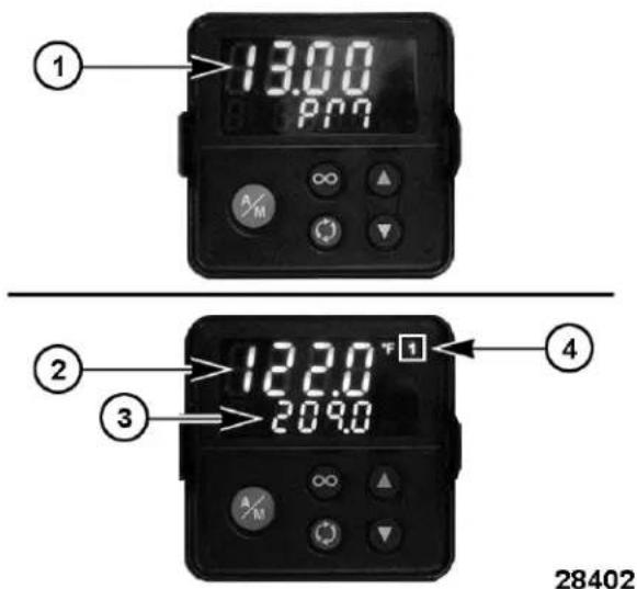
Fig. 64
| PID Controller Display | |
| Item Description | |
| 1 Program version during power on/self diagnostics test. | |
| 2 Sensor probe temperature inside sensor tube (°F or °C). | |
| 3 Set point temperature. Maximum operating temperature | |
| 4 | Output (number 1). Output is active when displayed. If blinking, power is being pulsed to heating elements. |
If PID controller or the sensor probe is malfunctioning, an error code will display.
Error Codes
- If Er.i1 error code is displayed, check sensor probe (thermocouple). Refer to SENSOR PROBE TEST - LWE MODEL.
- If a different error code is displayed, note code then contact Technical Support for further instructions.
- If display is not coming ON and water level and temperature conditions have been met, check wiring connections and power to the PID controller.
PID Operation Check
- Verify output (number 1) appears in top right corner of display when PID controller is powered and water temperature is below set point (209°F)
- When 1 is displayed, PIC controller is sending output signal to solid state contactor (3/6CON).
- When 1 is constantly displayed, solid state contactor is ON 100% .
NOTE: Pulsing of power begins when temperature reaches approximately 180° F.
- When 1 is blinking, solid state contactor is turning ON/OFF to pulse power to heating elements.
SENSOR PROBE TEST - LWE MODEL
WARNING
Certain procedures in this section require electrical test or measurements while power is applied to the machine. Exercise extreme caution at all times and follow Arc Flash procedures. If test points are not easily accessible, disconnect power and follow Lockout/Tagout procedures, attach test equipment and reapply power to test.
NOTE: The sensor probe is a J type thermocouple.
NOTICE
Lead wires are polarity sensitive. The negative lead (red) must be connected to PID Controller S1 terminal for proper operation.
- Access sensor probe wires connected to PID controller.
- Remove sensor probe wires from PID controller.
- Check thermocouple for a measurable resistance (approximately 5 to 10 ohms at room temperature).
- If meter reads an overload (OL) condition (open), or zero ohms (short) replace thermocouple.
PRESSURE SWITCH CHECK / ADJUST

WARNING
Certain procedures in this section require electrical test or measurements while power is applied to the machine. Exercise extreme caution at all times and follow Arc Flash procedures. If test points are not easily accessible, disconnect power and follow Lockout/Tagout procedures, attach test equipment and reapply power to test.
NOTE: Pressure can be checked with the small air pocket that exists between the delime port cap and water level probe housing in the delime hose. Make certain that no leaks exist in generator tank or pressure gauge fittings.
CHECK
- Remove following:
• RIGHT SIDE BOTTOM PANEL.
• LEFT SIDE BOTTOM PANEL.
• BOTTOM FRONT PANEL.
- Turn steamer OFF.
- Allow steamer to complete drain cycle.
- Close cooking compartment door.
- Remove cap from delime port and install pressure gauge.
- Turn steamer ON.
A. Set timer for approximately 10 minutes.
NOTE: Steam production is stabilized after approximately five fill cycles.
B. Wait for full steam production to stabilize. Observe LED on water control board to count cycles.
NOTICE
If pressure should rise above 5.0 psi when performing check, release clamp on steam outlet hose. Pressure switch is out of tolerance and must be adjusted.
NOTE: Operating pressures will vary slightly between steamer being serviced and gauge used.
NOTE: Pressure gauge will oscillate as fill water enters generator tank.
C. Observe pressure gauge once steam begins to be generated. Gauge should level out at approximately 1.25 to 2.0 psi.
- While observing pressure gauge:
A. Temporarily clamp steam outlet hose.
NOTE: Contactors should open when pressure is between 4.5 - 4.7 psi.
B. Listen for limiting and regulating contactors to OPEN.
C. Release clamp from steam outlet hose.
D. Listen for limiting and regulating contactors to CLOSE.
E. Record pressure reading.
F. Repeat steps above three times to find average cut-out pressure.
G. If pressure is outside of 4.5 - 4.7 psi, adjustment is necessary.
H. If cut-out pressure is within specifications, turn steamer off. Allow time for steamer to drain.
- Remove test gauge and reinstall delime cap.
ADJUST
- Set timer for approximately 10 minutes.
NOTE: Steam production is stabilized after approximately five fill cycles.
- Wait for full steam production to stabilize. Observe LED on water control board to count cycles.
NOTE: Make small incremental adjustments (1/8 turn of adjustment wheel) when adjusting cut-out pressure.
- Turn adjustment wheel (1, Fig. 65) to bring cut-out pressure into tolerance.

Fig. 65
- Turn adjustment wheel CCW to decrease cut-out pressure.
-
Turn adjustment wheel CW to increase cut-out pressure.
-
Check cut-off pressure after making adjustment.
-
Repeat CHECK and ADJUST as necessary until cut-out pressure is within 4.5 to 4.7 psi.
MANUAL DRAIN

WARNING
Disconnect the electrical power to the machine and follow lockout / tagout procedures.
- Turn off steamer water supply.
- Remove RIGHT SIDE TOP PANEL.
- Push in on manual drain knob and rotate 90° CCW.
- Drain tank.
- Rotate manual drain knob 90° CW to close valve.
| COMPONENT FUNCTION | |
| PID Controller...... | Monitors input signal from temperature sensor mounted in the sensor tube and regulates solid state contactor (3/6CON) as needed to maintain tank temperature for steam generation. On initial startup, the controller keeps the solid state contactor energized at 100% until temperature sensor approaches set point then begins pulsing power to the contactor as needed to maintain tank temperature. |
| Temperature Sensor...... | J type thermocouple mounted in the sensor tube (vent). Provides input signal to PID controller. |
| Solid State Contactor (3/6CON)...... | Modulates power to the tank heaters (through regulating contactor 2/5CON) when signaled by the PID controller. |
| Contactor, Limiting (1/4CON)...... | Connects one side of heating elements to incoming power. Energized whenever water level control (LLCO) coil is energized and the high limit thermostat and pressure switch are both closed. |
| Contactor, Regulating (2/5CON)...... | Connects one side of heating elements to power. On constantly during cooking cycle. |
| Drain Valve, Motorized (Ball type)...... | Motorized control for opening and closing drain valve. |
| Element, Heating...... | Located in steam generator tank. Heats water to produce steam. |
| Fuse, (1/4FU)...... | Slow blow 4A fuse. Located on primary side of main transformer. Protects control circuitry from over-currents. |
| Fuse, (2/5FU)...... | Slow blow 4A fuse. Located on primary side of main transformer. Protects control circuitry from over-currents. |
| Light (3/6LT), Power...... | Amber (AM) colored light. On when power switch is on (internal to power switch). |
| Light (2/5LT), Cook... | Red (RD) colored light. On when hold thermostat is satisfied and door is closed and timer is set. |
| Light (1/4LT), Ready...... | Green (GN) colored light. On when hold thermostat is satisfied. Latches on when hold thermostat is satisfied. |
| Water Level Control (WLC) Board...... | Controls water level by monitoring conditions of the 3 water level probes H, L and LLCO. |
| Probe (H)...... | High water level probe connected to internal latch relay circuit of the water level control board. Water must reach this level before internal latch relay is energized. |
| Probe (L)...... | Low water level probe connected to internal latch relay circuit of the water level control board. |
| Probe (LLCO)...... | Low Level Cut-Off (LLCO) probe. Controls power to heating and timer circuitry. Controls fast fill solenoid. |
| Relay (K1/K5)...... | Controlled by hold thermostat. Enables timer circuit. |
| Relay (K2/K6)LLCO...... | Low Level Cut-Off (LLCO) external relay. Only energized during drain. Controls Flush, Fast Fill and Vacuum Relief solenoids. |
| Relay (K3/K7) Drain Relay...... | Controlled by Time Delay Relay. Only energized during drain cycle. Controls WLC board and LLCO relay K2/K6 during the drain cycle. Disables heating and timer circuitry. |
| Relay (K4/K8)...... | Latches Ready light on. |
| Relay, Time Delay . . . | Controlled by the power switch. Output becomes active for 90 seconds when power switch is turned to off. Only used during drain cycle. |
| Solenoid (1SOL/6SOL), Cooling . . . . . . | Controlled by the condensate thermostat. Mixes cold water with hot condensate water from cooking chamber to reduce water temperature at drain. |
| Solenoid (2SOL/7SOL), Flush . . . . . . . | On only during drain cycle. Mixes cold water with tank water before entering drain box. Keeps drain hose clear of debris. |
| Solenoid (3SOL/8SOL), Fast Fill . . . . . . | Initial tank fill at a fast rate. Used during last stage of drain cycle to flush drain opening free of debris. |
| Solenoid (4SOL/9SOL), Slow Fill . . . . . | Secondary tank fill at a slow rate to prevent tank temperature from dropping rapidly. Energized as necessary during operation to replenish water in tank. |
| Solenoid (5SOL/10SOL), Vacuum Relief . . . . . . . . . | Provides open air line for vacuum relief during drain cycle to prevent cooking chamber flex. (Basic and Professional models only) |
| Switch (1S/3S), Power . . . . . . . . . . . | Two position rocker switch that controls machine steam and drain operations. Internal power light (3LT/6LT) indicates when switch is on. |
| Switch (2S/5S), Door . . . . . . . . . . . | Plunger activated, switch is wired in series with timer. When switch is closed and timer is set to a time or constant, regulating contactor will be energized 100% of the time once ready light is on (hold thermostat satisfied). |
| Switch (1PAS/2PAS), Pressure . . . . . . . . . . | Pressure cut-out protection. Cuts off electrical energy to the controls circuit if pressure rises above the upper tolerance level for the switch. |
| Thermostat (1TAS/4TAS), Condensate . . | Monitors temperature of water entering the facility drain system. Controls the cooling solenoid during cooking operation and the cooling and flush solenoids during drain cycle (135°F cut-in). |
| Thermostat (2TAS/5TAS), High-Limit . . . . | Protects against heating element over temperatures generally caused by tank boiling dry. A capillary tube device. Bulb is mounted directly to the heating element and high-limit body is mounted to a bracket on the frame rail (257°F cut-out). |
| Thermostat (3TAS/6TAS), Hold . . . . . . . . . | Controls temperature of water in steam generator tank to 195°F (closes at 195°F). |
| Timer (1TR/2TR) . . . . | Used for timed cook cycles from 0 to 60 minutes. Professional models have a CONSTANT position for continuous steam operation. |
| Transformer (1T/3T), Main . . . . . . . . . . . | Step down transformer from line voltage to control voltage level (120 VAC). |
| Transformer (2T/4T), Drain . . . . . . . . . . | Provides 24 VAC for motorized drain valve during drain cycle. |
| Buzzer . . . . . . . . . . | Creates audible signal when timed cook cycle is complete. |
COMPONENT LOCATION
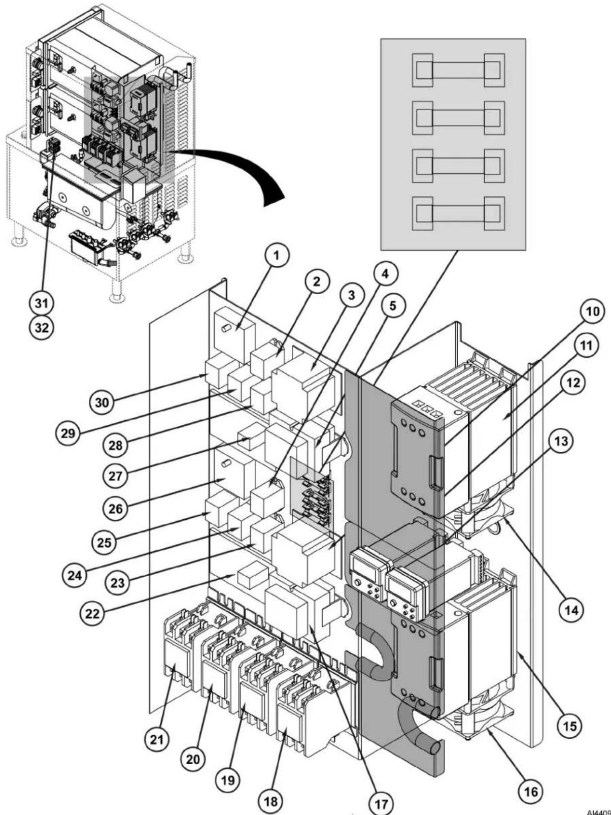
Electrical Panel (LWE Model)
| Item Number Nomenclature | |
| 1 Time Delay Relay 1 | |
| 2 Relay K4 | |
| 3 Transformer 2T | |
| 4 Relay K8 | |
| 5 Transformer 1T | |
| 6 Fuse 1FU | |
| 7 Fuse 2FU | |
| 8 Fuse 3FU | |
| 9 Fuse 4FU | |
| 10 Transformer 3T | |
| 11 Solid State Contactor (3 CON) | |
| 12 PID Controller 1 | |
| 13 PID Controller 2 | |
| 14 Fan (Part Of Contactor 3 CON) | |
| 15 Solid State Contactor (6 Con) | |
| 16 Fan (Part Of Contactor 6 CON) | |
| 17 Transformer 4T | |
| 18 Regulating Contactor (5CON) | |
| 19 Limiting Contactor (4CON) | |
| 20 Regulating Contactor (2CON) | |
| 21 Limiting Contactor (1CON) | |
| 22 Water Level Control PCB 2 | |
| 23 Relay K7 | |
| 24 Drain Relay K6 | |
| 25 LLCO Relay K5 | |
| 26 Time Delay Relay 2 | |
| 27 Water Level Control PCB 1 | |
| 28 Drain Relay K3 | |
| 29 LLCO Relay K2 | |
| 30 Relay K1 | |
| 31 Over-Temperature Switch 1 | |
| 32 Over-Temperature Switch 2 |

Electrical Panel (Standard / Professional Models)
| Item Number Nomenclature | |
| 1 Time Delay Relay | |
| 2 Relay K4 | |
| 3 Transformer T2 | |
| 4 Relay K8 | |
| 5 Transformer T1 | |
| 6 Fuse 1FU | |
| 7 Fuse 2FU | |
| 8 Fuse 3FU | |
| 9 Fuse 4FU | |
| 10 Transformer T3 | |
| 11 Regulating Contactor (5CON) | |
| 12 Limiting Contactor (4CON) | |
| 13 Regulating Contactor (2CON) | |
| 14 Limiting Contactor (1CON) | |
| 15 Water Level Control PCB 2 | |
| 16 Relay K8 | |
| 17 Drain Relay K6 | |
| 18 Relay K5 | |
| 19 Time Delay Relay 2 | |
| 20 Water Level Control PCB 1 | |
| 21 Drain Relay K3 | |
| 22 LLCO Relay K2 | |
| 23 Relay K1 | |
| 24 Over-Temperature Switch 1 | |
| 25 Over-Temperature Switch 2 |


Cooking Compartment and Controls
AI4411
| Item Number Nomenclature | |
| 1 Door Sensor | |
| 2 Buzzer | |
| 3 Atmospheric Vent | |
| 4 Timer | |
| 5 Indicator Lights | |
| 6 ON/OFF Switch | |
| 7 Latch | |
| 8 Pan Rack | |
| 9 Door Handle | |
| 10 Door | |
| 11 Thermocouple (LWE Models Only) | |
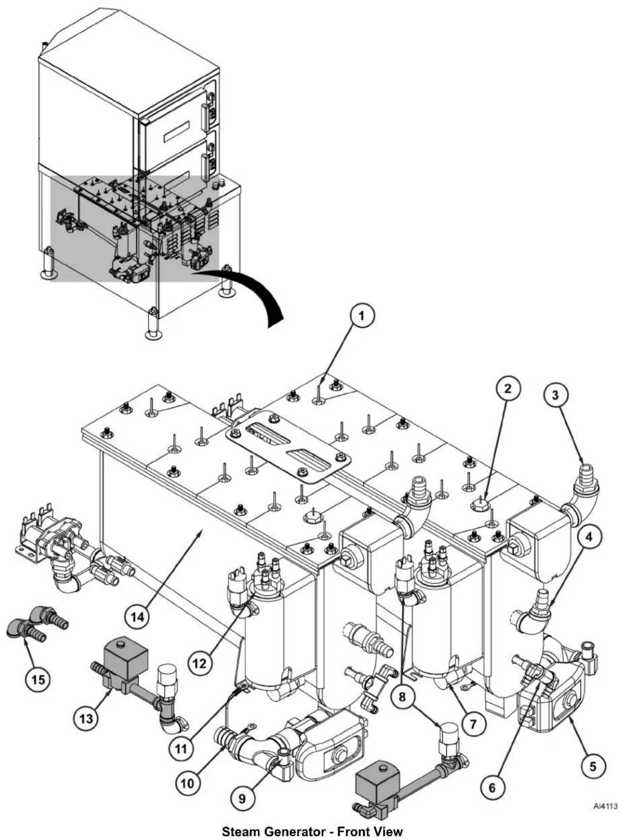
| Item Number Nomenclature | |
| 1 Heating Element Lead | |
| 2 High Limit Switch Probe | |
| 3 Steam Outlet Port | |
| 4 Deliming Port | |
| 5 Motorized Drain Valve | |
| 6 Filtered Water Inlet Port | |
| 7 Hold / Cycling Thermostat | |
| 8 High Pressure Limit | |
| 9 Flush Port | |
| 10 Drain Port | |
| 11 Steam Generator 2 Ground Bond Strap | |
| 12 Water Level Probes | |
| 13 Vacuum Relief Valve (Basic / Professional Only) | |
| 14 Steam Generator Tank | |
| 15 Vacuum Relief Valve Port (Basic / Professional Only) |

Steam Generator - Rear View
AI4112
| Item Number Nomenclature | |
| 1 Check Valves (Filtered Water Supply Lines) | |
| 2 Steam Generator 2 Slow Fill Valve | |
| 3 Steam Generator 2 Fast Fill Valve | |
| 4 Steam Generator 1 Slow Fill Valve | |
| 5 Steam Generator 2 Fast Fill Valve | |
| 6 Drain Flush Valve 2 | |
| 7 Cold Water Condensate Valve 2 | |
| 8 Drain Flush Valve 1 | |
| 9 Cold Water Condensate Valve 2 | |
| 10 Drain Box | |
| 11 Steam Generator 1 Ground Bond Strap | |
| 12 Super-heaters (Professional Only) | |
NOTE: Lower steamer unit components are referenced in Sequence of Operation. Upper steamer unit components operate in same manner.
Refer to the correct wiring diagram for model being serviced when reviewing sequence of operation.
NOTE: If power switch is set to off when service voltage is applied, steamer will enter the timed drain cycle.
-
Conditions
-
Steamer connected to correct voltage (120VAC present across X1 & X2 on secondary side of main transformer).
- Steamer connected to water supply with correct water requirements.
- Power switch is off.
- Condensate thermostat is open.
• High limit thermostat closed. - Pressure switch is closed.
- Hold thermostat open.
- Drain open and steam generator tank (referred to as tank) is empty.
- Steamer door open.
- Timer is off.
- Time delay relay timed out. Timer has no output on terminal 1.
• Water level control (WLC) board and tank properly grounded.
-
ON/OFF lever pushed in.
-
Manual linkage closes drain valve and operates power switch.
• N.O. contacts close.
• Power light (3LT - amber) illuminates.
• X1 potential to L1 of WLC board.
• 120VAC across L1 & L2 of WLC board.
- High Level (HL) coil energized on WLC board.
- HL LED on WLC board lights.
- Slow fill solenoid energized through closure of HL contacts.
- Tank fills.
-
Water level reaches Low Level Cut-Off (LLCO) probe.
-
LLCO coil is energized. LLCO LED on WLC board lights.
-
LLCO N.O. contacts close enabling heating element circuit.
-
Limiting and regulating contactor coils energize.
• Power to heating element.
- Tank water heats.
- Water level reaches Low (L) level probe.
- No action as Internal Latching Relay (ILR-1) contacts are open.
-
Water level reaches High (H) level probe.
-
ILR coil on WLC board energizes.
- HL coil de-energized by ILR-2 contacts opening.
-
Slow fill solenoid de-energized by opening of HL contacts on WLC board.
-
Tank water reaches 195° F.
- Hold thermostat contacts close.
- Relay K1 energizes.
- Timer circuit is enabled through closure of N.O. contacts K1-5/3 and K1-6/4.
- Temperature in tank is maintained at 195°F by hold thermostat control of regulating contactor through relay contacts K1-1/5.
-
Timer knob set to time other than zero.
-
Timer motor energized through closure of N.O. contacts K1-6/4 when time set is greater than zero.
- Door switch closure allows 120VAC across timer wires 18 & 19.
- Timer counts down from set time.
-
Tank temperature maintained by control of regulating contactor coil through N.O. contacts K1-6/4 and (Timer -1/3, door switch, K1-5/3).
-
Steamer door is closed.
-
Regulating contactor remains energized as long as time remains on timer and door is closed.
-
Heating element energized continuously.
-
Temperature of condensate exiting cooking cavity increases to above 135° F.
-
Condensate thermostat closes energizing cooling solenoid 1SOL.
-
Condensate is cooled in drain box before entering facility drain system.
-
Door opened during timed cook cycle.
-
Timer continues count down until time equals zero even if steamer door is opened.
-
Regulating contactor de-energized until below 195°F .
-
Time reaches zero.
- Buzzer is energized through N.O. contacts K1-6/4 and timer - 1/4.
- Buzzer remains energized until timer knob is turned to OFF, new time is set or drain handle is pulled out (power switch off).
- Drain handle pulled out. Tank drains.
• Power light (1LT-Amber) turns off.
- Time delay relay is energized through terminals 2 & 3 for set time (90 seconds). Output (120VAC) on terminal 1.
• Time delay relay output energizes K3 coil.
• X1 potential to L1 of WLC board through N.O. contacts K3-5/3.
- LLCO relay K2 coil energized through closed N.O. contacts K3-5/3, WLC board N.O. contacts LLCO and N.O. contacts K3-6/4.
- Drain flush solenoid enabled by closure of N.O. contacts K2-3/5.
- Heating element and timer control circuits are disabled by opening of N.C. contacts K3-6/2.
- Condensate thermostat reaches 135° F cut-in temperature, contacts close. Drain water temperature is regulated through condensate thermostat.
- Cooling solenoid and drain flush solenoid energized through cycling of condensate thermostat.
- Tank water level drops below L probe.
- ILR coil de-energizes.
- HL coil energized on WLC board. HL LED on WLC board lights.
-
Tank water level drops below LLCO probe.
-
LLCO relay K2 de-energized through opening of WLC board LLCO N.O. contacts.
- Drain flush solenoid energized through N.C. contacts (K2-6/2).
-
Flush/fast fill solenoid energized through N.C. contacts K2-6/2 and K2-5/1.
• Vacuum relief solenoid is energized through closed N.O. contacts K2-2/6. -
Time delay relay time elapses.
-
Power (120VAC) removed from output of time delay relay terminal 1.
- All solenoids, coils and WLC board are de-energized.
NOTE: Lower steamer unit components are referenced in Sequence of Operation. Upper steamer unit components operate in same manner.
Refer to the correct wiring diagram for model being serviced when reviewing sequence of operation.
NOTE: If power switch is set to off when service voltage is applied, steamer will enter the timed drain cycle.
1. Conditions
- Steamer connected to correct voltage (120VAC potential across X1 & X2 on secondary side of main transformer).
- Steamer connected to water supply with correct water requirements.
- Power switch is in off position.
- Condensate thermostat is open.
• High limit thermostat closed. - Pressure switch is closed.
- Hold thermostat open.
- Drain closed and steam generator tank (referred to as tank) is empty.
- Steamer door open.
- Timer is off.
- Time delay relay timed out. Timer has no output on terminal 1.
• Water level control (WLC) board and tank properly grounded.
2. Power switch (1S) is turned on.
• Power light (3LT - amber) illuminates.
• X1 potential to L1 of WLC board.
• 120VAC across L1 & L2 of WLC board.
- High Level (HL) coil energized on WLC board. HL LED on WLC board lights.
- Fast fill solenoid (3SOL) energized through N.C. contacts K3-1/5, N.C. contacts WLC (LLCO) and N.C. contacts K2-5/1.
- Tank begins to fill with water.
-
Water level reaches Low Level Cut-Off (LLCO) probe.
-
LLCO coil is energized. LLCO LED on WLC board lights.
- LLCO N.C. contacts open de-energizing fast fill solenoid.
- LLCO N.O. contacts close enabling timer and heating element circuits.
4. Limiting contactor coil energizes.
- Regulating contactor coil energizes through N.C. contacts K1-1/5.
• Power to heating element.
- Tank water heats.
-
Tank water reaches 195° F.
-
Hold thermostat contacts close.
- Slow fill solenoid is energized through closure of cycling thermostat (3TAS) and closed WLC (HL) N.O. contacts.
- Tank continues to fill.
-
Relay K1 energizes. Timer circuit is enabled through closure of N.O. contacts K1-6/4 and K1-5/3.
-
Ready light (1LT - green) illuminates.
- Relay K4 energizes. Latch circuit is completed by closure of N.O. contacts K4-5/3.
• Super-heater energizes through closure of N.O. contacts K4-6/4.
- Ready light (1LT - green) lights.
- Temperature in tank is maintained at 195°F by cycling thermostat control of regulating contactor through N.C. contacts K1-1/5.
7. Water level reaches Low (L) level probe.
- No action as Internal Latching Relay (ILR-1) contacts are open.
8. Water level reaches High (H) level probe.
A. ILR coil on WLC board energizes.
B. HL coil de-energized by ILR-2 contacts opening.
C. Slow fill solenoid de-energized by opening of HL contacts on WLC board.
D. HL LED on WLC board turns off.
9. Timer knob set to CONSTANT (continuous steam operation) or timed setting.
- Power (120VAC) present to door switch wire #19.
- If timer is set to a timed setting, timer motor is energized through closure of N.O. contacts K1-6/4.
-
Count down time begins.
-
Steamer door is closed.
-
Door switch (2S) contacts close. Cook light (2LT - red) illuminates.
-
Regulating contactor remains energized as long as door is closed and timer is set to CONSTANT or time remains on timed cycle.
-
Temperature of condensate exiting cooking cavity increases to above 135° F.
-
Condensate thermostat closes energizing cooling solenoid 1SOL.
-
Condensate is cooled in drain box before entering facility drain system.
-
Door opened during timed cook cycle.
-
Timer continues count down until time equals zero even if steamer door is opened.
-
Regulating contactor de-energizes and cook light turns off.
-
Time reaches zero.
-
Buzzer is energized through N.O. contacts K1-6/4 and timer - 11/14.
-
Buzzer remains energized until timer knob is turned to OFF, new time or CONSTANT is selected or steamer is turned off.
-
Power switch (1S) pushed to off.
-
Power (3LT), cook (2LT) and ready (1LT) lights turn off.
- Time delay relay is energized through terminals 2 & 3. Output (120VAC) on terminal 1 for 90 seconds.
- Time delay relay output energizes K3 coil.
• X1 potential to L1 of WLC board through N.O. contacts K3-3/5.
- Relay K2 coil energized through WLC N.O. contacts LLCO and N.O. contacts K3-6/4.
- Heating element and timer control circuits are disabled by opening of N.C. contacts K3-6/2.
- Power (120VAC) across primary of drain transformer.
- Motorized drain valve energized.
- Drain valve opens and tank begins to drain.
-
Drain valve N.O. contacts close.
-
Condensate thermostat reaches 135° F, contacts close.
-
Drain water temperature is regulated through condensate thermostat.
• Cooling solenoid (1SOL) energized through closure of condensate thermostat contacts. -
Flush solenoid (2SOL) energized through closure of N.O. contacts K2-3/5 and drain valve N.O. contacts.
-
Tank water level drops below L probe.
-
ILR coil de-energizes.
-
HL coil energized on WLC board. HL LED on WLC board lights.
-
Tank water level drops below LLCO probe.
-
Relay K2 de-energized through opening of WLC board LLCO N.O. contacts.
• Vacuum relief solenoid energized through N.C. contacts K2-2/6. - Fast fill solenoid energized through WLC (LLCO) N.C. contacts and N.C. contacts K2-5/1.
-
Flush solenoid (2SOL) remains energized through WLC (LLCO) N.C. contacts.
-
Time delay relay time elapses.
-
Power (120VAC) removed from output of time delay relay terminal 1.
- All solenoids, coils and WLC board are de-energized.
- Motorized drain valve de-energized.
- Drain valve closes.
NOTE: Lower steamer unit components are referenced in Sequence of Operation. Upper steamer unit components operate in same manner.
Refer to the correct wiring diagram for model being serviced when reviewing sequence of operation.
NOTE: If power switch is set to off when service voltage is applied, steamer will enter the timed drain cycle.
-
Conditions.
-
Steamer connected to correct voltage (120VAC potential across X1 & X2 on secondary side of main transformer).
- Steamer connected to water supply with correct water requirements.
• Power switch is in off position. - Condensate thermostat open.
• High limit thermostat closed. - Pressure switch closed.
- Hold thermostat open.
- Drain closed and steam generator tank (referred to as tank) is empty.
- Steamer door open.
- Timer is off.
- Time delay relay timed out. Timer has no output on terminal 1.
• Water Level Control (WLC) board and tank properly grounded. -
PID controller and solid state contactor are off.
-
Power switch (1S) is turned on.
• Power light (3LT - amber) illuminates.
• X1 potential to L1 of WLC board.
• 120VAC across L1 & L2 of WLC board.
- High Level (HL) coil energized on WLC board.
- HL LED on WLC board lights.
- Fast fill solenoid (3SOL) energized through N.C. contacts K3-1/5, N.C. contacts WLC (LLCO) and N.C. contacts K2-5/1.
-
Tank begins to fill with water.
-
Water level reaches Low Level Cut-Off (LLCO) probe.
-
LLCO coil is energized. LLCO LED on WLC board lights.
- LLCO N.C. contacts open de-energizing fast fill solenoid.
-
LLCO N.O. contacts close enabling timer and heating element circuits.
-
Limiting contactor coil and solid state contactor cooling fan energize through N.C K3-6/2 contacts.
- Regulating contactor coil and power to the PID controller energize through N.C. contacts K1-1/5.
-
Temperature measured in the sensor tube (vent) is below PID controller set point. PID controller signals solid state contactor to modulate power to the heating elements through regulating contactor load contacts. Tank water heats.
-
Tank water reaches 195° F.
-
Hold thermostat contacts close.
- Slow fill solenoid is energized through closure of hold thermostat (3TAS) and closed WLC (HL) N.O. contacts. Tank continues to fill.
- Relay K1 energizes.
- Timer circuit is enabled through closure of N.O. contacts K1-6/4 and K1-5/3.
- Relay K4 energizes - Latch circuit is completed by closure of N.O. contacts K4-5/3.
- Ready light (1LT - green) lights.
NOTE: PID controller governs operation of solid state contactor and provides power to load contacts on regulating contactor to power heating elements.
-
Regulating contactor and PID controller de-energized when K1-1/5 N.C. contacts open.
• Temperature in tank cycles between 195°F (hold thermostat setting) and 209°F (PID controller set point). -
Water level reaches Low (L) level probe.
- No action. The internal latching relay (ILR-1) contacts are open.
-
Water level reaches High(H) level probe.
-
Internal latching relay (ILR) coil on WLC board energizes.
- High Level (HL) coil de-energized by ILR-2 contacts opening.
- Slow fill solenoid de-energized by opening of HL contacts on WLC board.
-
HL LED on WLC board turns off.
-
Timer knob set to CONSTANT (for continuous steam operation) or timed setting.
-
Power (120VAC) present to door switch wire #19.
-
If timer is set to a timed setting, Timer motor is energized through closure of N.O. contacts K1-6/4. Count down time begins when door is closed.
-
Steamer door is closed.
-
Door switch (2S) contacts close. Cook light (2LT - red) illuminates.
- Regulating contactor and PID controller remain energized as long as door is closed and timer is set to CONSTANT or time remains on timed cycle.
- Steam flows from the steam generator into the cooking compartment to begin cooking product. Uncondensed steam flows out of the cooking compartment through the compartment drain and up the sensor tube (vent) where the temperature sensor is mounted. The temperature sensor output is monitored by the PID controller.
-
As temperature in sensor tube approaches set point, the PID controller signals the solid state contactor to change the pulse rate to the steam generator heating elements, limiting the production of excess steam (unabsorbed energy).
-
Under some conditions, the temperature of condensate exiting the cooking compartment and entering the drain box may exceed 135° F. When this occurs:
- Condensate thermostat closes and energizes cooling solenoid. Condensate is cooled in drain box before entering facility drain system.
-
Door opened during timed cook cycle.
-
Timer continues count down until time equals zero even if steamer door is opened.
-
Regulating contactor and PID controller deenergize. Tank heat and cook light turn off.
-
Time reaches zero.
-
Buzzer is energized through N.O. contacts K1-6/4 and Timer - 11/14.
-
Buzzer remains energized until timer knob is turned to OFF, new time or CONSTANT is selected or steamer is turned off.
-
Power switch (1S) pushed to off.
- Power (3LT), cook (2LT) and ready (1LT) lights turn off.
- Time delay relay is energized through terminals 2 & 3. Output (120VAC) on terminal 1 for 90 seconds.
• Time delay relay output energizes K3 coil.
• X1 potential to L1 of WLC board through N.O. contacts K3-3/5.
- Relay K2 coil energized through WLC N.O. contacts LLCO and N.O. contacts K3-6/4.
- Heating element and timer control circuits are disabled by opening of N.C. contacts K3-6/2.
- Power (120VAC) across primary of drain transformer. Motorized drain valve energized. Drain valve opens and tank begins to drain.
- Drain valve N.O. contacts close.
- Power removed from PID controller. Solid state contactor de-energized.
- Condensate thermostat reaches 135° F, contacts close. Drain water temperature is regulated through condensate thermostat.
• Cooling solenoid energized through closure of Condensate Thermostat contacts.
- Flush solenoid energized through closure of N.O. contacts K2-3/5 and drain valve N.O. contacts.
- Tank water level drops below L probe.
- ILR coil de-energizes.
- HL coil energized on WLC board.
-
HL LED on WLC board lights.
-
Tank water level drops below LLCO probe.
-
Relay K2 de-energized through opening of WLC board LLCO N.O. contacts.
- Fast fill solenoid energized through WLC (LLCO) N.C. contacts and N.C. contacts K2-5/1.
-
Flush solenoid remains energized through WLC (LLCO) N.C. contacts.
-
Time delay relay time elapses.
-
Power (120VAC) removed from output of time delay relay terminal 1.
- All solenoids, coils and WLC board are de-energized.
- Motorized drain valve de-energized. Drain valve closes.
DIAGRAMS
WIRING DIAGRAMS

flowchart
graph TD
    subgraph Left_Circuit
        A["MAIN TRANSFORMER (T1)"] --> B["CONSERGATE THERMOSTATIC (LSD)"]
        B --> C["THEK DELAY CONTROL"]
        C --> D["DRAIN PELAY (R3)"]
        D --> E["FLUSH SULMOND (SOL)"]
        E --> F["POWER (LT)"]
        F --> G["POWER (LT)"]
        G --> H["POWER (LT)"]
        H --> I["POWER (LT)"]
        I --> J["POWER (LT)"]
        J --> K["POWER (LT)"]
        K --> L["POWER (LT)"]
        L --> M["POWER (LT)"]
        M --> N["POWER (LT)"]
        N --> O["POWER (LT)"]
        O --> P["POWER (LT)"]
        P --> Q["POWER (LT)"]
        Q --> R["POWER (LT)"]
        R --> S["POWER (LT)"]
        S --> T["POWER (LT)"]
        T --> U["POWER (LT)"]
        U --> V["POWER (LT)"]
        V --> W["POWER (LT)"]
        W --> X["POWER (LT)"]
        X --> Y["POWER (LT)"]
        Y --> Z["POWER (LT)"]
        Z --> AA["POWER (LT)"]
        AA --> AB["POWER (LT)"]
        AB --> AC["POWER (LT)"]
        AC --> AD["POWER (LT)"]
        AD --> AE["POWER (LT)"]
        AE --> AF["POWER (LT)"]
        AF --> AG["POWER (LT)"]
        AG --> AH["POWER (LT)"]
        AH --> AI["POWER (LT)"]
        AI --> AJ["POWER (LT)"]
        AJ --> AK["POWER (LT)"]
        AK --> AL["POWER (LT)"]
        AL --> AM["POWER (LT)"]
        AM --> AN["POWER (LT)"]
        AN --> AO["POWER (LT)"]
        AO --> AP["POWER (LT)"]
        AP --> AQ["POWER (LT)"]
        AQ --> AR["POWER (LT)"]
        AR --> AS["POWER (LT)"]
        AS --> AT["POWER (LT)"]
        AT --> AU["POWER (LT)"]
        AU --> AV["POWER (LT)"]
        AV --> AW["POWER (LT)"]
        AW --> AX["POWER (LT)"]
        AX --> AY["POWER (LT)"]
        AY --> AZ["POWER (LT)"]
        AZ --> BA["POWER (LT)"]
        BA --> BB["POWER (LT)"]
        BB --> BC["POWER (LT)"]
        BC --> BD["POWER (LT)"]
        BD --> BE["POWER (LT)"]
        BE --> BF["POWER (LT)"]
        BF --> BG["POWER (LT)"]
        BG --> BH["POWER (LT)"]
        BH --> BI["POWER (LT)"]
        BI --> BJ["POWER (LT)"]
        BJ --> BK["POWER (LT)"]
        BK --> BL["POWER (LT)"]
        BL --> BM["POWER (LT)"]
        BM --> BN["POWER (LT)"]
        BN --> BO["POWER (LT)"]
        BO --> BP["POWER (LT)"]
        BP --> BQ["POWER (LT)"]
        BQ --> BR["POWER (LT)"]
        BR --> BS["POWER (LT)"]
        BS --> BT["POWER (LT)"]
        BT --> BU["POWER (LT)"]
        BU --> BV["POWER (LT)"]
        BV --> BW["POWER (LT)"]
        BW --> BX["POWER (LT)"]
        BX --> BY["POWER (LT)"]
        BY --> BZ["Power"]
    end

    subgraph Right_Circuit
        C
        D
        E
        F
        G
        H
        I
        J
        K
        L
        M
        N
        O
        P
    end

    subgraph Left_Detected_Circuit
        B
        C
    end

    subgraph Left_Peak_Circuit
        D
    end

    subgraph Left_Control_Circuit
        E
    end

    subgraph Left_Detected_Air_Circuit
        F
    end

    subgraph Left_Control_Air_Detected_Air_Circuit
    G
    end

    subgraph Left_Control_Bit_Circuit
        H
    end

    subgraph Left_Control_Bit_Detected_Bit_Circuit
    I
    end

    subgraph Left_Control_Circuit
        J
    end

    subgraph Left_Control_Detected_Detected_Circuit
    K
    end

    subgraph Left_Control_Ear_Circuit
        L
    end

    subgraph Left_Control_Ear_Detected_Ear_Circuit
    M
    end

    subgraph Left_Control_Ear_Bit_Circuit
        N
    end

    subgraph Left_Control_Ear_Detected_Bit_Circuit
    O
    end

    subgraph Left_Control_Ear_Bit_Detected_Bit_Detected_Circuit
    P
    end

    subgraph Left_Control_Ear_Bit_Detected_Bit_Detected_Detected_Circuit
    Q
    end

    subgraph Left_Control_Ear_Bit_Detected_Bit_Detected_Detected_Detected_Circuit
    R
    end

    subgraph Left_Control_Ear_Bit_Detected_Bit_Detected_Detected_Detected_Detected_Circuit
    S
    end

    subgraph Left_Control_Ear_Bit_Detected_Bit_Detected_Detected_Detected_Detected_Detected_Detected_Circuit
    T
    end

    subgraph Left_Control_Ear_Bit_Detected_Bit_Detected_Detected_Detected_Detected_Detected_Detected_Detected_Detected_Detected_Detected_Circuit
    U
    end

    subgraph Left_Control_Ear_Bit_Detected_Bit_Detected_Detected_Detected_Detected_Detected_Detected_Detected_Detected_Detected_Detected_Circuit
    V
    end

    subgraph Left_Control_Ear_Bit_Detected_Bit_Detected_Detected_Detected_Detected_Detected_Detected_Detected_Detected_Detected_Detected_Detected_Circuit
    W
    end

    subgraph Left_Control_Ear_Bit_Detected_Bit_Detected_Detected_Detected_Detected_Detected_Detected_Detected_Detected_Detected_Detected_Detected_Detected_Circuit
    X
    end

    subgraph Left_Control_Ear_Bit_Detected_Bit_Detected_Detected_Detected_Detected_Detected_Detected_Detected_Detected_Detected_Detected_Detected_Circuit
    Y
    end

    subgraph Left_Control_Ear_Bit_Detected_Bit_Detected_Detected_Detected_Detected_Detected_Detected_Detected_Detected_Detected_Detected_Circuit
    Z
    end

    subgraph Left_Control_Ear_Bit_Detected_Bit_Detected_Detected_Detected_Detected_Detected_Detected_Detected_Detected_Detected_Circuit
    AA
    end

    subgraph Left_Control_Ear_Bit_Detected_Bit_Detected_Detected_Detected_Detected_Detected_Detected_Detected_Detected_Circuit
    AB
    end

    subgraph Left_Control_Ear_Bit_Detected_Bit_Detected_Detected_Detected_Detected_Detected_Detected_Detected_Detected_Circuit
    AC
    end

    subgraph Left_Control_Ear_Bit_Detected_Bit_Detected_Detected_Detected_Detected_Detected_Detected_Detected_Detected_Circuit
    AD
    end

    subgraph Left_Control_Ear_Bit_Detected_Bit_Detected_Detected_Detected_Detected_Detected_Detected_Sheet_2.5_1_1_1_1_1_1_1_1_1_1_1_1_1_1_1_1_1_1_1_1_1_1_1_1_1_1_1_1_1_1_1_1_1_1_1_1_1_1_1_1_1_1_1_1_1_1_1_1_1_1_2_2_2_2_2_2_2_2_2_2_2_2_2_2_2_2_2_2_2_2_2_2_2_2_2_2_2_2_2_2_2_2_2_2_2_2_2_2_2_2_2_2_2_2_2_2_2_2_2_2_4 4 4 4 4 4 4 4 4 4 4 4 4 4 4 4 4 4 4 4 4 4 4 4 4 4 4 4 4 4 4 4 4 4 4 4 4 4 4 4 4 4 4 4 4 4 4 4 4 4 4,6 6 6 6 6 6 6 6 6 6 6 6 6 6 6 6 6 6 6 6 6 6 6 6 6 6 6 6 6 6,6,8,8,8,8,8,8,8,8,8,8,8,8,8,8,8,8,8,8,8,8,8,8,8,8,8,8,8,8,8,8,8,8,8,8,8,8,8,8,8,8,8,8,8,8,8,8,8,8,8,8, & DRY LEAST LEAST LEAST LEAST LEAST LEAST LEAST LEAST LEAST LEAST LEAST LEAST LEAST LEAST LEAST LEAST LEAST LEAST LEAST LEAST LEAST LEAST LEAST LEAST LEAST LEAST LEAST LEAST LEAST LEAST LEAST LEAST LEAST LEAST LEAST LEAST LEAST LEAST LEAST LEAST LEAST LEAST LEAST LEAST LEAST LEAST LEAST LEAST LEAST LEAST LEAT LEAST LEAST LEAST LEAST LEAST LEAST LEAST LEAST LEAST LEAST LEAST LEAST LEAST LEAST LEAST LEAST LEAST LEAST LEAST LEAST LEAST LEAST LEAST LEAST LEAST LEAST LEAST LEAST LEAST LEAST LEAST LEAST LEAST LEAST LEAST LEAST LEAST LEAST LEAST LEAST LEAST LEAST LEAST LEAST LEAST LEAST LEAST LEAST LEAST LEAF LEAST LEAST LEAST LEAST LEAST LEAST LEAST LEAST LEAST LEAST LEAST LEAST LEAST LEAST LEAST LEAST LEAST LEAST LEAST LEAST LEAST LEAST LEAST LEAST LEAST LEAST LEAST LEAST LEAST LEAST LEAST LEAST LEAST LEAST LEAST LEAST LEAST LEAST LEAST LEAST LEAST LEAST LEAST LEAST LEAST LEAST LEAST LEAST LEAST LEACTLELELELELELELELELELELELELELELELELELELELELELELELELELELELELELELELELELELELELELELELELELELELELELELELELELELELELELELELELELELELELELELELELELELELELELELELELELELELELELELELELELELELELELELELELELELELELELELELELELELELE-TERIE STT.
    AC
    end

Legend:
- CONSERGATE THERMOSTATIC (LSD)
- CONSERGATE THERMOSTATIC (LSD)
- CONSERGATE THERMOSTATIC (LSD)
- CONSERGATE THERMOSTATIC (LSD)
- CONSERGATE THERMOSTATIC (LSD)
- CONSERGATE THERMOSTATIC (LSD)
- CONSERGATE THERMOSTATIC (LSD)
- CONSERGATE THERMOSTATIC (LSD)
- CONSERGATE THERMOSTIC THERMOSTATIC (LSD)
- CONSERGATE THERMOSTIC THERMOSTIC THERMOSTIC THERMOSTIC THERMOSTIC THERMOSTIC THERMOSTIC THERMOSTIC THERMOSTIC THERMOSTIC THERMOSTIC THERMOSTIC THERMOSTIC THERMOSTIC THERMOSTIC THERMOSTIC THERMOSTIC THERMOSTIC THERMOSTIC THERMOSTIC THERMOSTIC THERMOSTIC THERMOSTIC THERMOSTIC THERMOSTIC THERMOSTIDLETILELLING THERMOSTATIC (LSD)
- CONSERGATE THERMOSTATIC (LSD)
- CONSERGATE THERMOSTATIC (LSD)
- CONSERGATE THERMOSTATIC (LSD)
- CONSERGATE THERMOSTATIC (LSD)
- CONSERGATE THERMOSTATIC (LSD)
- CONSERGATE THERMOSTATIC (LSD)
- CONSERGATE THERMOSTATIC (LSD)
 - CONSERGATE THERMOSTATIC(TEKT) REE SHEET-2.5 REE SHEET-2.5 REE SHEET-2.5 REE SHEET-2.5 REE SHEET-2.5 REE SHEET-2.5 REE SHEET-2.5 REE SHEET-2.5 REE SHEET-2.5 REE SHEET-2.5 REE SHEET-2.5 REE SHEET-2.5 REE SHEET-2.5 REE SHEETS-3.5 REE SHEETS-3.5 REE SHEETS-3.5 REE SHEETS-3.5 REE SHEETS-3.5 REE SHEETS-3.5 REE SHEETS-3.5 REE SHEETS-3.5 REE SHEETS-3.5 REE SHEETS-3.5 REE SHEETS-3.5 REE SHEETS-3.5 REE SHEETS-3.5 REA REA REA REA REA REA REA REA REA REA REA REA REA REA REA REA REA REA REA REA REA REA REA REA REA REA REA REA REA REA REA REA REA REA REA REA REA REA REA REA REA REA REA REA REA REA REA REA REA REA REBRENT FOR PRINT PSB409-1]
ALI405
C24ET6 / 10 Wiring Diagram (Sheet 1)
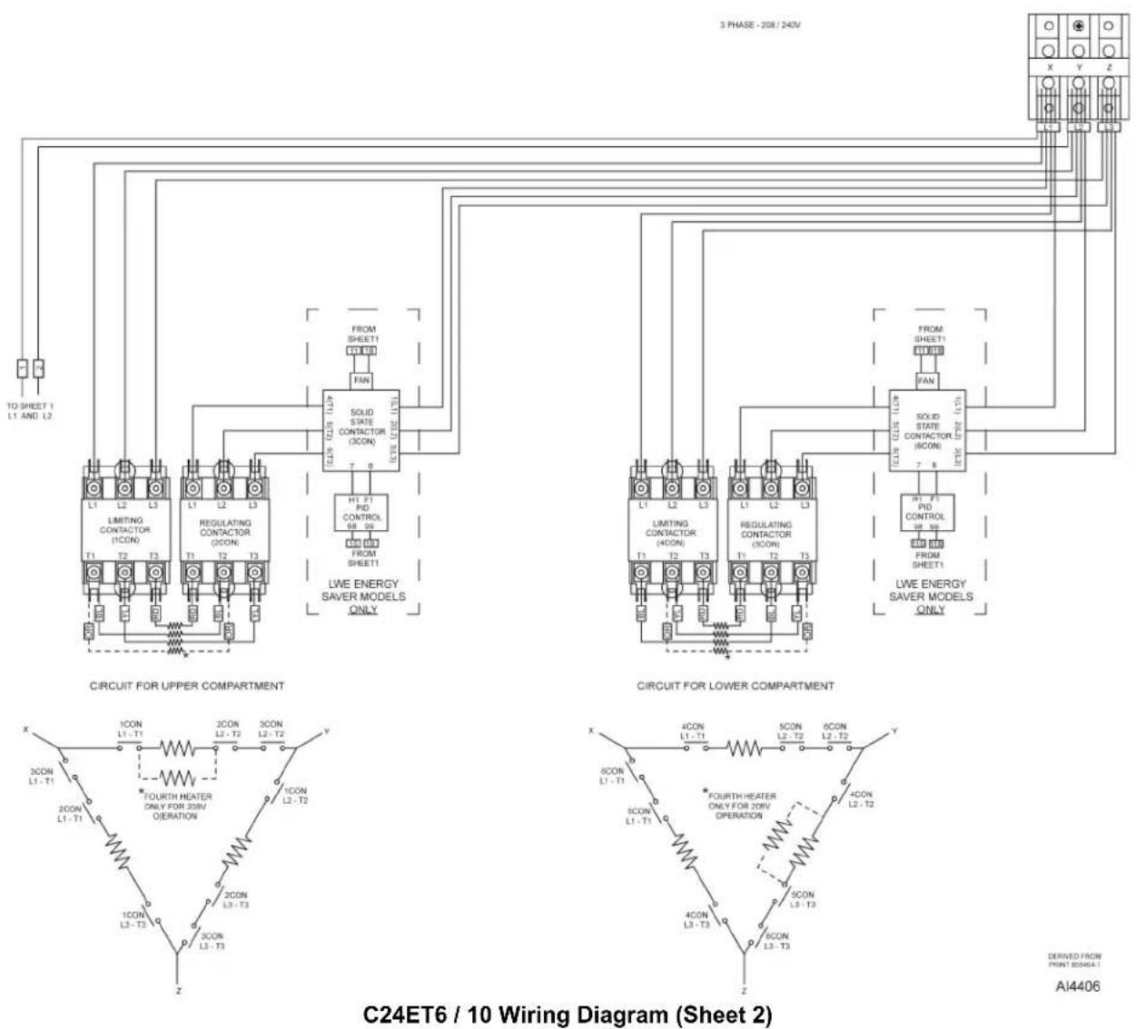
DERIVED FROM PRINT 850464-1
AI4406

flowchart
graph TD
    subgraph_Upper_Compartment["3 PHASE - WYE"]
        A1["TO SHEET 1 L1 AND L2"] --> B1["Limiting Contactor (ICON) T1 T2 T3"]
        A2["REGULATING CONCTOR (ICON) T1 T2 T3"] --> B2["SOLID STATE CONTACTOR (ICON) T1 T2 T3"]
        A3["LIVE ENERGY SAVER MODELS ONLY"] --> B3["FROM SHEET1"]
        B1 --> C1["FOH F1 PID CONTROL 08-09"]
        B2 --> C2["FOH F1 PID CONTROL 08-09"]
        B3 --> C3["FOH F1 PID CONTROL 08-09"]
        C1 --> D1["FOH F1 PID CONTROL 08-09"]
        C2 --> D2["FOH F1 PID CONTROL 08-09"]
        C3 --> D3["FOH F1 PID CONTROL 08-09"]
        D1 --> E1["FOH F1 PID CONTROL 08-09"]
        D2 --> E2["FOH F1 PID CONTROL 08-09"]
        D3 --> E3["FOH F1 PID CONTROL 08-09"]
        E1 --> F1["FOH F1 PID CONTROL 08-09"]
        E2 --> F2["FOH F1 PID CONTROL 08-09"]
        E3 --> F3["FOH F1 PID CONTROL 08-09"]
    end
    subgraph_Lower_Compartment["3 PHASE - WYE"]
        G1["TO SHEET 1 L1 AND L2"] --> H1["Limiting Contactor (ICON) T1 T2 T3"]
        G2["REGULATING CONCTOR (ICON) T1 T2 T3"] --> H2["SOLID STATE CONTACTOR (ICON) T1 T2 T3"]
        G3["LIVE ENERGY SAVER MODELS ONLY"] --> H3["FOH F1 PID CONTROL 08-09"]
        G4["LIVE ENERGY SAVER MODELS ONLY"] --> H4["FOH F1 PID CONTROL 08-09"]
        H1 --> I1["FOH F1 PID CONTROL 08-09"]
        H2 --> I2["FOH F1 PID CONTROL 08-09"]
        H3 --> I3["FOH F1 PID CONTROL 08-09"]
        I1 --> J1["FOH F1 PID CONTROL 08-09"]
        I2 --> J2["FOH F1 PID CONTROL 08-09"]
        I3 --> J3["FOH F1 PID CONTROL 08-09"]
        J1 --> K1["FOH F1 PID CONTROL 08-09"]
        J2 --> K2["FOH F1 PID CONTROL 08-09"]
        K1 --> L1["FOH F1 PID CONTROL 08-09"]
        K2 --> L2["FOH F1 PID CONTROL 08-09"]
        L1 --> M1["FOH F1 PID CONTROL 08-09"]
        L2 --> M2["FOH F1 PID CONTROL 08-09"]
        M1 --> N1["FOH F1 PID CONTROL 08-09"]
        M2 --> N2["FOH F1 PID CONTROL 08-09"]
    end
    subgraph_Lower_Compartment["CIRCUIT FOR UPPER COMPARTMENT"]
        O1["3CON L1-T1"] --> P1["2CON L1-T1"]
        O2["2CON L2-T2"] --> P2["3CON L2-T2"]
        O3["3CON L3-T3"] --> P3["4CON L3-T3"]
        O4["4CON L4-T4"] --> P5["5CON L4-T4"]
    end
    subgraph_Lower_Lower_Compartment["CIRCUIT FOR LOWER COMPARTMENT"]
        Q1["6CON L1-T1"] --> R1["6CON L1-T1"]
        Q2["6CON L2-T2"] --> R2["6CON L2-T2"]
        Q3["6CON L3-T3"] --> R3["6CON L3-T3"]
    end
    style Upper_Compartment fill:#f9f,stroke:#333
    style Lower_Lower_Compartment fill:#ccf,stroke:#333
C24ET6 / 10 Wiring Diagram (Sheet 3)

C24ET6 / 10 Wiring Diagram (Sheet 4)
UPPER COMPARTMENT

208 1 PHASE PROFESSIONAL
FIELD CONVERSION NOTES:
1) FOR 240V MACHINES, DISCONNECT AND CAP THE ORANGE WIRES OF THE MAIN HEATING ELEMENT AND CHANGE WIRE #3 TO THE CORRESPONDING VOLTAGE TAP (H3/240V) ON THE TRANSFORMER
2) FOR PLUS MACHINES, THERE IS NO SUPERHEATER
858764-1
REV. A1
WATER / STEAM DIAGRAM

flowchart
graph TD
    A["Unfiltered Water Supply"] --> B["Cold Water Condensate Valve"]
    A --> C["Drain / Flush Valve"]
    B --> D["4.8 GPM"]
    C --> E["0.15 GPM"]
    F["Filtered Water Supply"] --> G["Cold Water Condensate Valve"]
    F --> H["Drain / Flush Valve"]
    G --> I["4.8 GPM"]
    H --> J["0.15 GPM"]
    K["Steam Generator 1"] --> L["Motorized Drain Valve"]
    L --> M["Vent"]
    N["Cooking Compartment 1 (Upper)"] --> O["Steam Generator 2"]
    O --> P["Motorized Drain Valve"]
    P --> Q["Cooking Compartment 2 (Lower)"]
    R["Fast Fill Valve"] --> S["4.8 GPM"]
    T["Slow Fill Valve"] --> U["0.75 GPM"]
    V["Fast Fill Valve"] --> W["4.8 GPM"]
    X["Slow Fill Valve"] --> Y["0.75 GPM"]
Fig. 77
TROUBLESHOOTING
ALL MODELS
WARNING
Certain procedures in this section require electrical test or measurements while power is applied to the machine. Exercise extreme caution at all times and follow Arc Flash procedures. If test points are not easily accessible, disconnect power and follow Lockout/Tagout procedures, attach test equipment and reapply power to test.
Refer to LWE MODEL for faults unique to the LWE models.
| Symptom Possible Causes | |
| Compartment leaks water or steam around door. | Unit not level.Compartment drain screen obstructed.Drain line obstructed, undersized, exceeds 6 feet or not to an open gap drain.Door gasket worn or damaged. Refer to DOORGASKETfor removal procedure. |
| Cold water condenser not operating properly. | Flush solenoid (2/5SOL) inoperative or plugged.Lack of water supply.Condensate thermostat (1/4TAS) stuck open.Cooling solenoid (1/6SOL) valve inlet screen clogged or malfunction. |
| Steam generated inside cooking compartment when timer is off. | High limit thermostat (2TAS) or related heat control circuit malfunction.Relay K1/K5 malfunction. |
| Water or steam leaking inside panels. | Steam generator gasket not sealing.Loose clamps around steam hose or hose malfunction; or loose steam line plumbing connections.Cooking compartment or steam generator malfunction. |
| Tank water level too high. | Slow fill solenoid (4/9SOL) or fast fill solenoid (3/8SOL) does not shut off.High level probe malfunction (open circuit).Water Level Control (WLC) board inoperative . |
| Tank does not fill. | ·Water supply not on.·Slow fill solenoid (4/9SOL) or fast fill solenoid (3/8SOL) not being energized or plugged.·WLC board malfunction.·Water level probes shorted to ground. |
| Heat coming on without water in tank. | ·Dirty low level cut-off probe (shorted to ground) or low level cut-off probe wire grounded.·Limiting (1/4CON) or regulating contactor (2/5CON) malfunction.·WLC - LLCO contacts stuck closed. WLC board malfunction. |
| Steamer will not heat. | ·No incoming voltage (circuit breaker tripped or fuses open).·Tank not filled (supply water off; fast fill solenoid clogged or malfunction).·Power switch malfunction.·WLC board malfunction.·Relay (K1/K5) malfunction.·High-limit thermostat open (2/5TAS).·Heating elements inoperative (open circuit).·Limiting contactor (1/4CON) or regulating contactor (2/5CON) malfunction.·Hold thermostat open (3/6TAS).·Relay (K3/7) malfunction.·Water too pure for probes to properly conduct electricity. |
| Timer motor does not run. | ·Relay K1/K5-6/4 contacts not closing.·Timer malfunction. |
| Water running out of drain during fill. | ·Motorized drain valve stuck open.·Time delay relay malfunction.·Condensate thermostat (1/4TAS) malfunction. |
| Door not closing properly. | ·Door latch assembly.·Striker adjustment. |
| Door won't open. | Latch won't release. Refer to DOOR LATCH ADJUSTMENT. |
| Buzzer not operating. | ·Timer malfunction.·Buzzer malfunction. |
LWE MODEL

WARNING
Certain procedures in this section require electrical test or measurements while power is applied to the machine. Exercise extreme caution at all times and
follow Arc Flash procedures. If test points are not easily accessible, disconnect power and follow Lockout/Tagout procedures, attach test equipment and reapply power to test.
This section applies only to LWE model specific faults. Refer to ALL MODELS for general troubleshooting.
| Symptom Possible Causes | |
| Steamer will not heat. | PID controller malfunction.Solid state contactor (3/6CON) malfunction.Sensor probe open or disconnected from PID controller. Display cycles between:Top row "----" and "Er.i1".Bottom row "Attn" and "0.0". |
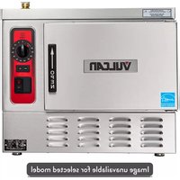
- C24ET-SERIES STEAMERS
- - NOTICE -
- TABLE OF CONTENTS
- GENERAL
- INTRODUCTION
- BASIC Steamers
- PROFESSIONAL Steamers
- LWE Steamers
- Steam Cooking
- OPERATION
- INSTALLATION
- LUBRICATION
- CLEANING
- ELECTRICAL SPECIFICATIONS - BASIC / PROFESSIONAL MODELS
- ELECTRICAL SPECIFICATIONS - LWE MODEL
- WATER SPECIFICATIONS - ALL MODELS
- NOTICE
- Water Conditioning
- TOOLS
- Standard
- Special
- REMOVAL AND REPLACEMENT OF PARTS
- RIGHT SIDE BOTTOM PANEL
- WARNING
- LEFT SIDE TOP PANEL
- LEFT SIDE BOTTOM PANEL
- TOP REAR PANEL
- BOTTOM REAR PANEL
- BOTTOM FRONT PANEL
- TOP COVER
- DOOR
- DOOR GASKET
- DOOR HANDLE
- Removal
- DOOR LATCH
- HINGE BEARINGS
- DRAIN BOX
- CONDENSATE THERMOSTAT
- HEATING ELEMENT
- STEAM GENERATOR TANK
- MOTORIZED DRAIN VALVE (PROFESSIONAL)
- Drain Tank Manually
- 2nd GENERATION
- 1st GENERATION
- SUPER-HEATER ELEMENT
- HOLD THERMOSTAT
- HIGH LIMIT THERMOSTAT
- WATER LEVEL PROBES
- SENSOR PROBE
- UPPER COOKING COMPARTMENT
- LOWER COOKING COMPARTMENT
- PRESSURE SWITCH
- VACUUM RELIEF VALVE
- FILL VALVES
- ELECTRONIC COMPONENT
- PID CONTROLLER
- SOLID STATE CONTACTOR
- ON/OFF SWITCH
- INDICATOR LIGHT ASSEMBLY
- DOOR SWITCH
- TIMER
- BUZZER
- SERVICE PROCEDURES AND ADJUSTMENTS
- DOOR LATCH ADJUSTMENT
- JAMMED DOOR
- Door Adjustment
- HEATING ELEMENT DIAGNOSTIC CHECK - LWE MODELS
- HEATING ELEMENT DIAGNOSTIC CHECK - BASIC / PROFESSIONAL MODELS
- SUPER-HEATER DIAGNOSTIC CHECK - PROFESSIONAL MODELS
- PID CONTROLLER TEST - LWE MODEL
- Error Codes
- PID Operation Check
- SENSOR PROBE TEST - LWE MODEL
- PRESSURE SWITCH CHECK / ADJUST
- CHECK
- ADJUST
- MANUAL DRAIN
- Conditions
- Power switch (1S) is turned on.
- Limiting contactor coil energizes.
- Water level reaches Low (L) level probe.
- Water level reaches High (H) level probe.
- Timer knob set to CONSTANT (continuous steam operation) or timed setting.
- DIAGRAMS
- WIRING DIAGRAMS
- FIELD CONVERSION NOTES:
- TROUBLESHOOTING
- ALL MODELS
- LWE MODEL
Brand : Vulcan
Model : C24ET6-LWE
Category : Steam cleaner