OG-300 - Heating Ravanson - Free user manual and instructions
Find the device manual for free OG-300 Ravanson in PDF.


| Product Type | Electric Fan Heater |
| Brand | Ravanson |
| Model | OG-300 |
| Dimensions (H x W x D) | 25 x 20 x 20 cm |
| Weight | 1.2 kg |
| Power Source | AC 220-240V, 50Hz |
| Power Consumption | 2000 W |
| Heating Elements | PTC Ceramic |
| Fan Speeds | 2 (Low/High) |
| Thermostat | Adjustable, 5°C - 35°C |
| Timer | 0-12 hours |
| Safety Features | Overheat protection, tip-over switch, cool-touch housing |
| Noise Level | < 45 dB |
| Room Coverage | Up to 25 m² |
| Control Type | Mechanical dials |
| Display | LED indicator |
| Maintenance | Wipe with dry cloth, do not immerse |
| Spare Parts | Fan blade, heating element (contact support) |
| Repairability Index | 7/10 (user-replaceable parts) |
| Certifications | CE, RoHS |
Frequently Asked Questions - OG-300 Ravanson
User questions about OG-300 Ravanson
0 question about this device. Answer the ones you know or ask your own.
Ask a new question about this device
Download the instructions for your Heating in PDF format for free! Find your manual OG-300 - Ravanson and take your electronic device back in hand. On this page are published all the documents necessary for the use of your device. OG-300 by Ravanson.
USER MANUAL OG-300 Ravanson
natural_image
Line drawing of a tall outdoor heater with mesh insulation and ventilation grilles (no text or symbols)MODEL: OG-300
natural_image
Simple line drawing of a lamp inside a transparent cube (no text or symbols)natural_image
Technical line drawing of a mechanical testing apparatus with labeled components (L and GG), no readable text or symbols beyond labels.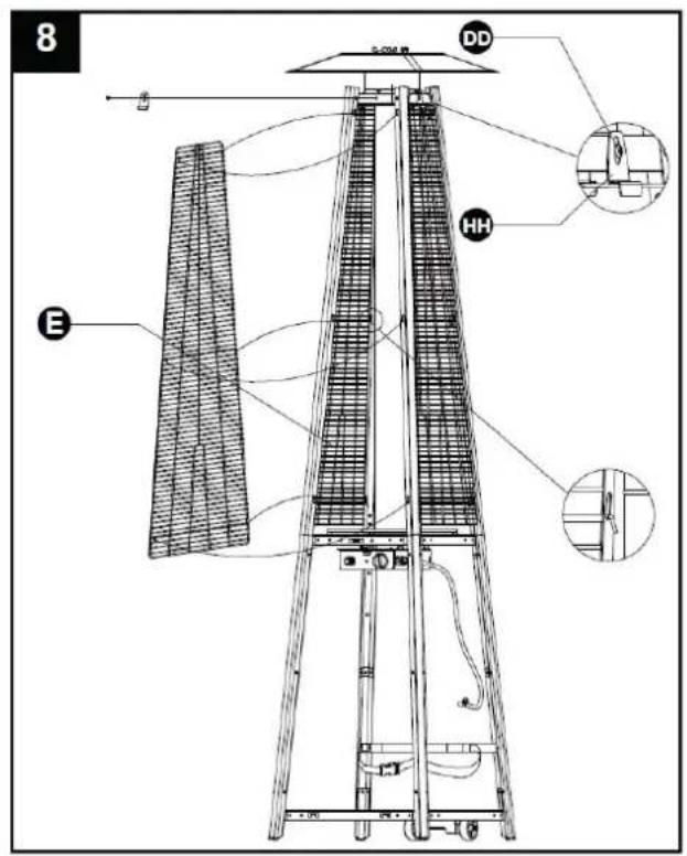
natural_image
Technical line drawing of a gas cylinder mounted on a ladder, with an inset showing a close-up of the component (no text or symbols present)natural_image
Technical line drawing of a mechanical component with no visible text or symbols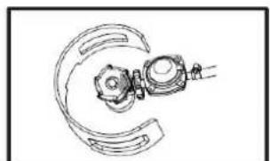
natural_image
Pure mechanical component diagram without any text, numbers, or symbols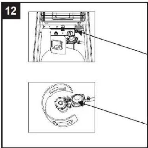
NAJCZĘSTSZE PROBLEMY
Before first use, read carefully every warnings and safety instructions.

The failure to comply with the below-mentioned safety warnings and instructions, incorrect installation and use of the device can cause serious injuries or death due to scalds, fire, or carbon oxide poisoning.

Please keep this warnings and safety instructions in order to be able to future use.
GENERAL SAFETY INSTRUCTIONS

The device must be installed in accordance with the applicable law and used only outside.
ALWAYS READ THE OPERATING MANUAL BEFORE INSTALLING AND USING THE DEVICE.
FOR YOUR SAFETY
-
If you smell gas:
-
Shut off gas to the appliance.
- Extinguish any open flame.
-
If odor continues, immediately call your gas supplier or your fire Department.
-
Do not store or use gasoline or other flammable vapors and liquids in the vicinity of this or any other appliance.
- An LP cylinder not connected for use shall not be stored in the vicinity of this or any other appliance.
WARNING
1) For use outdoors or in amply ventilated areas.
2) An amply ventilated area must have a minimum of 25 % of the surface area open.
3) The surface area is the sum of the walls surface.
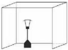
WARNING: Improper installation, adjustment, alteration, service or maintenance Can cause injury or property damage. Read the installation, operating and maintenance instructions thoroughly before installing or servicing this equipment.
WARNING
Read the instructions before installation and use.
-This appliance must be installed and the gas cylinder stored in accordance with the regulations in force;
-Do not obstruct the ventilation holes of the cylinder housing;
-Do not move the appliance when in operation;
-Shut off the valve at the gas cylinder or the regulator before moving the appliance;
-The tubing or the flexible hose must be changed within the prescribed intervals;
-Use only the type of gas and the type of cylinder specified by the manufacturer;
The LP tank used with your patio heater must meet the following requirements:
Purchase LP tanks only with these required measurements: (31.8cm) (diameter) x 58cm) (tall) with 15kg capacity maximum.
-In case of violent wind particular attention must be taken against tilting of the appliance; Keep the appliance at least 1m from the gas cylinder.
-The injector is installed by the manufacturer only.
Do not connect the gas cylinder directly to the appliance without regulator. Use only the type of gas and the type of cylinder specified in the instructions.
A regulator(compliees with EN16129:2013 and the national regulation)
of the correct pressure corresponding to the appliance category.
It's recommended to use flexible hose that approved by EN16436:2014.
CAUTION PLEASE READ CAREFULLY THE FOLLOWING SAFETY GUIDELINES BEFORE OPERATION.
- Do not use the patio heater for indoors, as it may cause personal injury or property damage.
- This outdoor heater is not intended to be installed on recreational vehicles and/or boats.
- Installation and repair should be done by a qualified service person.
- Improper installation, adjustment, alteration can cause personal injury or property damage.
- Do not attempt to alter the unit in any manner.
- Never replace or substitute the regulator with any regulator other than the factory-suggested replacement.
- Do not store or use gasoline or other flammable vapors or liquids in the heater unit.
- The whole gas system, hose, regulator, pilot or burner should be inspected for leaks or damage before use, and at least annually by a qualified service person.
- All leak tests should be done with a soap solution. Never use an open flame to check for leaks.
- Do not use the heater until all connections have been leak tested.
- Turn off the gas valve immediately if smell of gas is detected. Turn Cylinder Valve OFF. If leak is at Hose/
Regulator connection: tighten connection and perform another leak test. If bubbles continue appearing should be returned to hose's place of purchase. If leak is at Regulator/Cylinder Valve connection: disconnect, reconnect, and perform another leak check. If you continue to see bubbles after several attempts, cylinder valve is defective and should be returned to cylinder's place of purchase.
- Do not transport heater while it's operating.
- Do not move the heater after it has been turned off until the temperature has cooled down.
- Keep the ventilation opening of the cylinder enclosure free and clear of debris.
- Do not paint the radiant screen, control panel or top canopy reflector.
- Control compartment, burner and circulation air passageways of the heater must be kept clean.
Frequent cleaning may be required as necessary.
- The LP tank should be turned off when the heater is not in use.
-
Check the heater immediately if any of the following occurs:
-
The heater does not reach temperature.
- The burner makes popping noise during use (a slight noise is normal when the burner is extinguished).
-
Smell of gas in conjunction with extreme yellow tipping of the burner flames.
-
The LP regulator/hose assembly must be located out of pathways where people may trip over it or in area where the hose will not be subject to accidental damage.
-
Any guard or other protective device removed for servicing the heater must be replaced before operating the heater.
-
Adults and children should stay away from high temperature surface to avoid burns or clothing ignition.
-
Children should be carefully supervised when they are in the area of the heater.
-
Clothing or other flammable materials should not be hung on the heater or placed on or near the heater.
-
To change the gas cylinder in a amply ventilated area, away from any ignition source (candle, cigarettes, other flame producing appliances, ...);
-
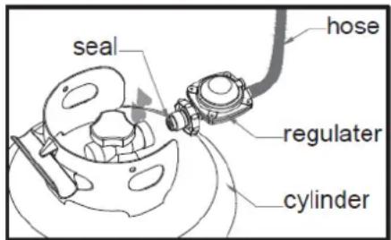
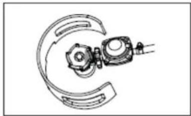
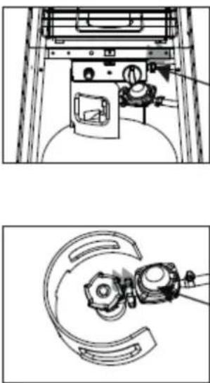
To check that the regulator seal is correctly fitted and able to fulfill its function showed as photo right;
-
To not obstruct the ventilation holes of the cylinder housing;
-
To close the gas supply at the valve of the gas cylinder or the regulator after use;
-
In the event of gas leakage, the appliance shall not be used or if alight, the gas supply shall be shut off and the appliance shall be investigated and rectified before it is used again;
-
To check the hose at least once per month, each time the cylinder is changed or each time before long time no use. If it shows signs of cracking, splitting or other deterioration it shall be exchanged for new hose of the same length and of the equivalent quality;
-
The use of this appliance in enclosed areas can be dangerous and is PROHIBITED;
-
Read the instructions before using this appliance. The appliance must be installed in accordance with the instructions and local regulations.
-
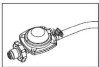
For connection of hose and regulator, and connection of regulator and hose, please refer to photo showed above.
PLEASE NOTE!
Liquefied gas is heavier than air which is why it tends to keep close to the floor. The gas cylinders cannot be located near sources of heat (ovens, fireplaces, stoves etc.) which could increase the temperature inside the cylinder to over 50^ C.
HEATER STAND AND LOCATION
The heater is primarily for outdoor use only.
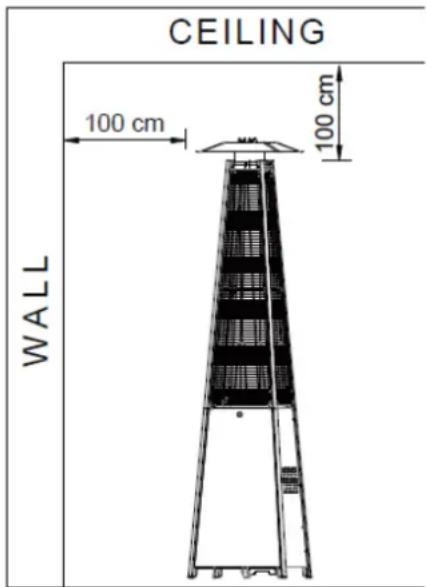
Always ensure that adequate fresh air ventilation is provided. Always maintain proper clearance to non-protected combustible materials i.e. top 100 cm and sides 100 cm minimum.
Heater must be placed on level firm ground.
Never operate heater in an explosive atmosphere like in areas where gasoline or other flammable liquids or vapors are stored.
To protect heater from strong wind, anchor the base securely to the ground with screws.
GAS REQUIREMENTS
- Use propane butane only.
- The pressure regulator and hose assembly to be used must conform to local standard codes.
- The installation must conform to local codes, or in the absence of local codes, with the standard for the storage and handling of liquid petroleum gases.
- A dented, rusted or damaged tank may be hazardous and should be checked by your tank supplier. Never use a tank with a damaged valve connection.
- The tank must be arranged to provide for vapor withdrawal from the operating cylinder.
- Never connect an unregulated tank to the heater.
LEAKAGE TEST
Gas connections on the heater are leak tested at the factory prior to shipment. A complete gas tightness check must be performed at the installation site due to possible mishandling in shipment or excessive pressure being applied to the heater.
Make a soap solution of one part liquid detergent and one part water. The soap solution can be applied with a spray bottle, brush or rag. Soap bubbles will appear in case of a leak.
The heater must be checked with a full cylinder.
Make sure the safety control valve is in the OFF position.
Turn the gas supply ON.
In case of a leak, turn off the gas supply. Tighten any leaking fittings, then turn the gas supply on and recheck.
Never leak test while smoking.
-
Turn on the valve on the gas supply cylinder completely'
-
Press and turn the variable knob t PILOT position (counter-clockwise 90°)
-
Press dawn the variable control knob and hold for 60 seconds. While holding down the variable control knob, press the igniter button several times until the pilot flame lights. Release the variable knob after the pilot flame lights.
Note:
- If a new tank has just been connected, please allow at least one minute for the air in the gas pipeline to purge out through the pilot hole.
- When lighting the pilot flame make sure that the variable control knob is continuously pressed down while pressing the igniter button. Variable control knob can be released after the pilot flame lights.
- If the pilot flame does not light or it goes out, repeat step 5
- After the pilot flame lights turn the variable control knob to maximum position and leave it there for 5 minutes or more before turning the knob to desired temperature position.
Warning; Check that no broken on the glass is found before operation.
TO TURN OFF THE HEATER
-
Turn the variable control knob to PILOT position
-
Press and turn the variable control knob to OFF position.
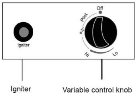
Off: the heater stop work Hi: maximum temperature position Lo: minimum temperature position
- Turn off the valve on the gas supply cylinder completely
Storage
- Always close the gas valve of the gas cylinder after use or in case a disturbance.
- Remove the pressure regulator and the hose.
- Check the tightness of the gas valve and for damage. If you suspect a damage, have it changed by your gas dealer.
- Never storage liquid gas cylinder in a sub-terrain, or at places without adequate air ventilation.
ATTENTION! It is strictly forbidden to use a gas garden heater outdoors during rainfall. Storing the gas garden heater outside the building is only allowed after covering it with a rain cover. In any other case, the device should be located in a place where it is protected against flooding and low temperatures.
When the device is at rest, it should be absolutely disconnected from the gas supply. (gas valve in closed position), all safety handles should be locked and the device should be secured against falling. If it is not possible to prevent the device from tipping over or falling out while it is left unattended, the gas cylinder should be disconnected and left in a safe place.
CLEANING AND CARE
- The device should be periodically inspected at least once a month or every time you replace a cylinder!
- Cleaning should take place regularly or as dust appears or dirt on the device!
- It is forbidden to make any changes to the device's structure!
- The heater should not be cleaned using corrosive agents! Please wipe powder-coated surfaces with a soft, damp cloth and remove any dirt from the burner to maintain cleanliness and safe use.
- Cover the burner with the optional protective cover when the heater is not in use.
- When replacing individual components, use only original parts available from the manufacturer.
PARTS AND SPECIFICATIONS
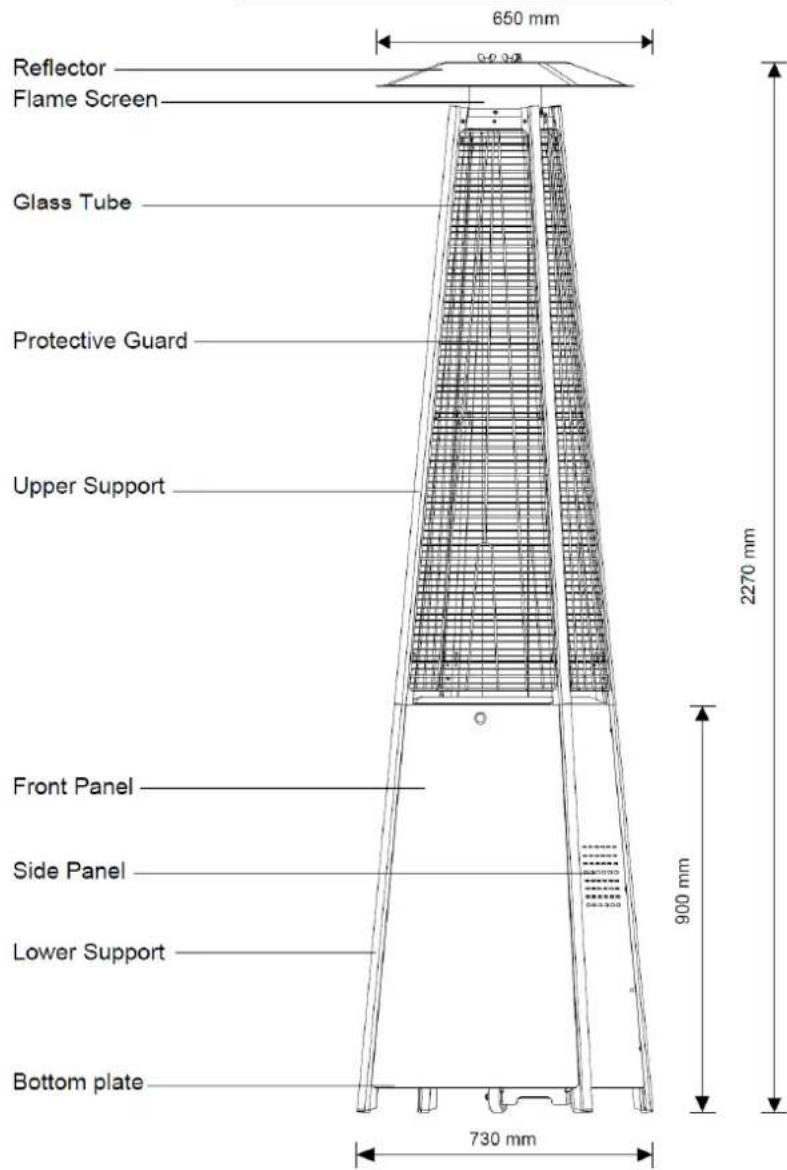
A. Construction and characteristics
Transportable terrace/garden heater with tank housing.
Casing in steel with powder-coating or in stainless steel.
Gas hose connections with metal clamp (screw caps for Germany).
Heat emission from reflector.
B. Specifications
Use propane, butane or their mixtures gas only.
Gas: G30 - 37 mbar
Category: I3B/P
Total heat input: 13kw
Gas consumption: 946g/h
Type: A
PIN: 0063CU7710
Country o destination PL (Poland)
Max. power: 13000 W; Min. power: 5000 W
Consumption:
| APPLIANCE CATEGORY: | I_3+(28-30/37) | I_3B/P(30) | I_3B/P(50) | I_3B/P(37) | |
| TYPES OF GAS: | Butane | Propane | Butane, propane or their mixtures | Butane, propane or their mixtures | Butane, propane or their mixtures |
| GAS PRESSURE: | 28-30mbar | 37 mbar | 30 mbar | 50mbar | 37mbar |
| OUTLET PRESSURE OF REGULATOR: | 30mbar | 37 mbar | 30 mbar | 50mbar | 37mbar |
Using the proper regulator according to outlet pressure of regulator as showed in the table above.
C. Table of injector
| APPLIANCE CATEGORY: | 13+(28-30/37) | 13B/P(30) | 13B/P(50) | 13B/P(37) | |
| TYPES OF GAS: | Butane | Propane | Butane, propane | Butane, propane | Butane, |
| GAS PRESSURE: | 28-30mbar | 37 mbar | 30 mbar | 50mbar | 37mbar |
| TOTAL HEAT INPUT (Hs): (Qn) | 13kW (G30:946g/h; G31:929g/h) | ||||
| INJECTOR SIZE: | 1.75 mm for main burner0.22 mm for pilot burner | 1.55 mm for main burner0.22 mm for pilot | 1.65 mm for main burner0.22 mm for | ||
| The marking, for example, 1.75 on the injector, indicates that the size of injector is1.75 mm | |||||
The hose and regulator assembly must conform to local standard codes.
Regulator outlet pressure should meet the corresponding appliance category in B.
Specification.
The appliance requires approved hose in 0.6m length.
The device can be supplied with gas in family 3: 3B/P – propane butane.
REGULATOR AND HOSE
To connect the gas, use a pressure reducing valve with the rated gas pressure of 37 mbar and flexible hose.
The hose should be secured to the regulator and the appliance with hose clips. Make sure the flexible hose could not come in contact with hot surface and avoid twisting.
Use a suitable regulator that is certified to EN 16129. To connect the gas, use a pressure reducing valve with the rated gas pressure of 37 mbar.
Please consult your LPG dealer for information regarding a suitable regulator for the gas cylinder.
Use only regulators and hose approved for LP Gas at the above pressures (37 mbar). The life expectancy of the regulator is estimated as 2 years.
The use of the wrong regulator or hose is unsafe; always check that you have the correct items before operating.
The hose used must conform to the relevant standard for the country of use. Worn or damaged hose must be replaced.
ASSEMBLY PARTS
ATTENTION! Connecting the gas garden heater to a liquefied gas cylinder, adjusting it and checking the tightness of the installation should only be performed by an authorized installer of gas equipment or a technician from an authorized service facility, in accordance with applicable regulations, which should be confirmed on the product warranty card. Lack of such confirmation invalidates the warranty!
Tools needed:
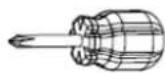
Screwdriver w/ medium blade
Spray bottle of soap solution for leakage test
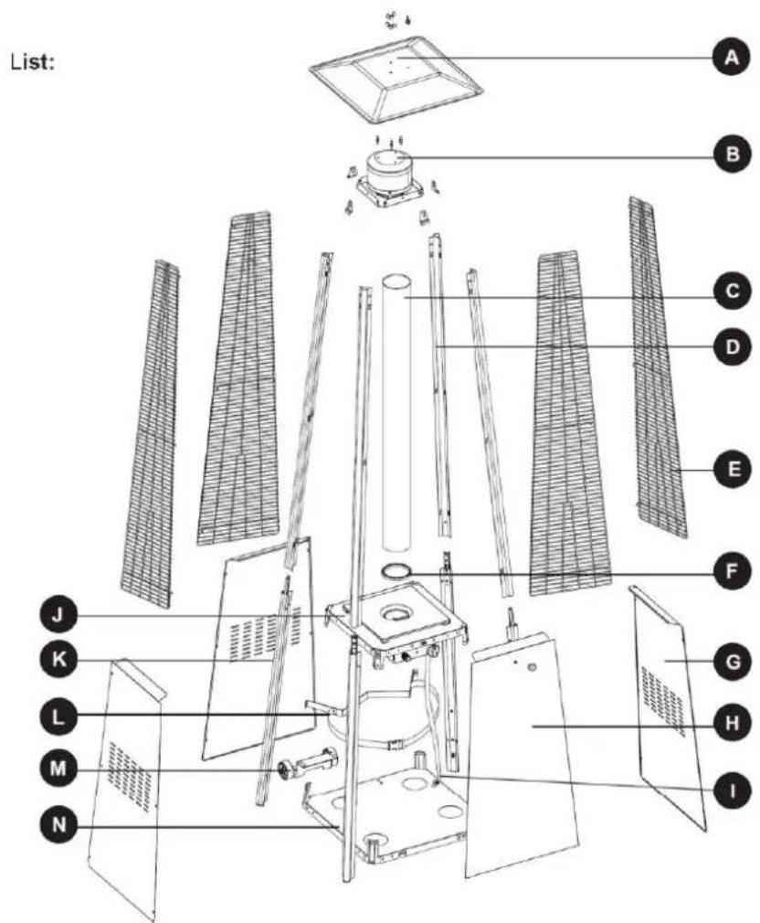
| PART | DESCRIPTION | QUANTITY |
| A | Reflector | 1 |
| B | Flame Screen | 1 |
| C | Glass Tube | 1 |
| D | Upper Support | 4 |
| E | Protective Guard | 4 |
| F | Black Silicone Ring | 1 |
| G | Side Panel | 3 |
| H | Front Panel | 1 |
| I | Gas Hose | 1 |
| J | Control Box Assy | 1 |
| K | Lower Support | 4 |
| PART | DESCRIPTION | QUANTITY |
| L | Block Belt | 1 |
| M | Wheel Assembly | 1 |
| N | Bottom Plate | 1 |
ASSEMBLY PARTS
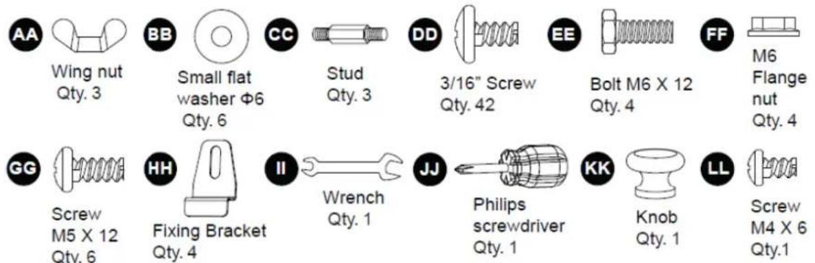
HARDWARE CONTENTS (shown actual size)

ASSEMBLY PROCEDURES
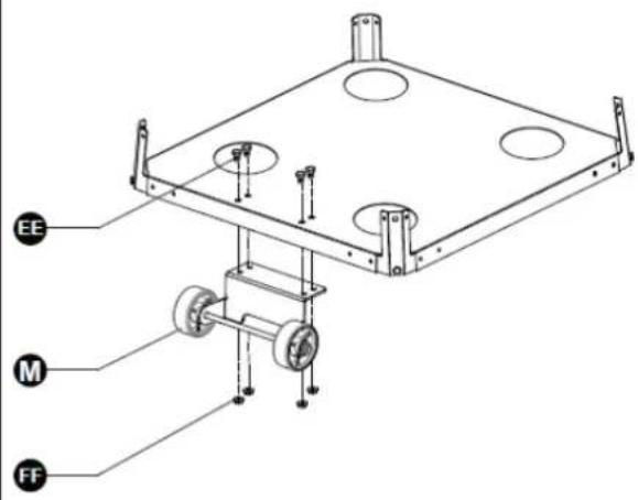
- Assemble the wheel assembly to the bottom plate. Fix the wheel assembly to the bottom plate using 4pcs bolt M6X12 and 4pcs flange nut M6.
Hardware Used

Bolt M6 X 12
× 4

M6 Flange nut

× 4

Wrench
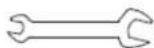
× 1
1
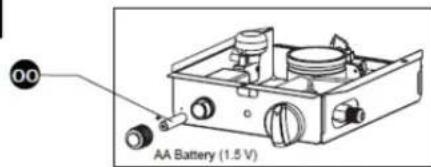
2-1. Unscrew the switch button, load small battery, tighten the switch button.
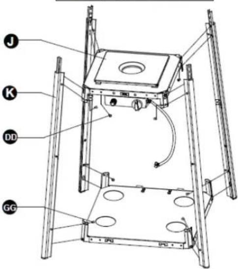
2-2. Insert the pins of the base to the holes of lower support, press to secure the pins. Using 4pcs screw M5X12 to secure the lower support and base.
Insert the pins of the control box assy to the holes of upper support, press to secure the pins. Using 4pcs screw 3/16" screw to secure the upper support and control box assy.
Hardware Used

Screw M5 X 12
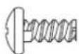
× 4

3/16" Screw
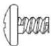
× 4

Philips screwdriver
× 1
2
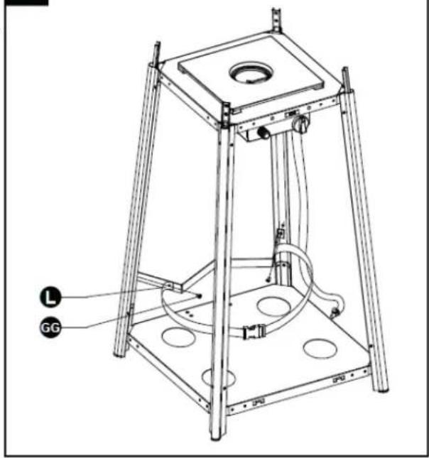
- Assemble block belt.
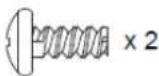
Fix the block belt to the 2pcs of lower support behind the front door, using 2pcs screw M5X12.
Hardware Used

Screw M5 X 12

Philips screwdriver
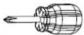
× 1
3
natural_image
Technical line drawing of a mechanical testing apparatus with labeled components (L and GG), no readable text or symbols beyond labels.- Assemble the middle support.
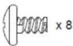
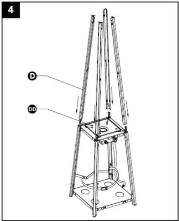
Insert the 4pcs upper support to the lower support. Secure them with 8pcs screw 3/16".
Hardware Used

3/16" Screw

Philips screwdriver
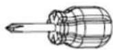
× 1
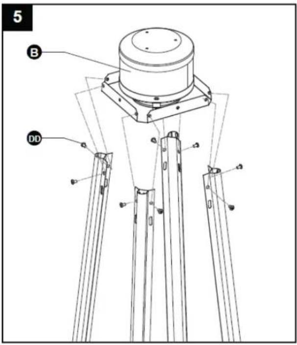
- Assebmle the flame screen to the upper support.
Secure the flame screen to the upper support using 8pcs screw 3/16".
Hardware Used

3/16" Screw
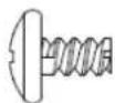
×8

Philips screwdriver
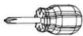
× 1
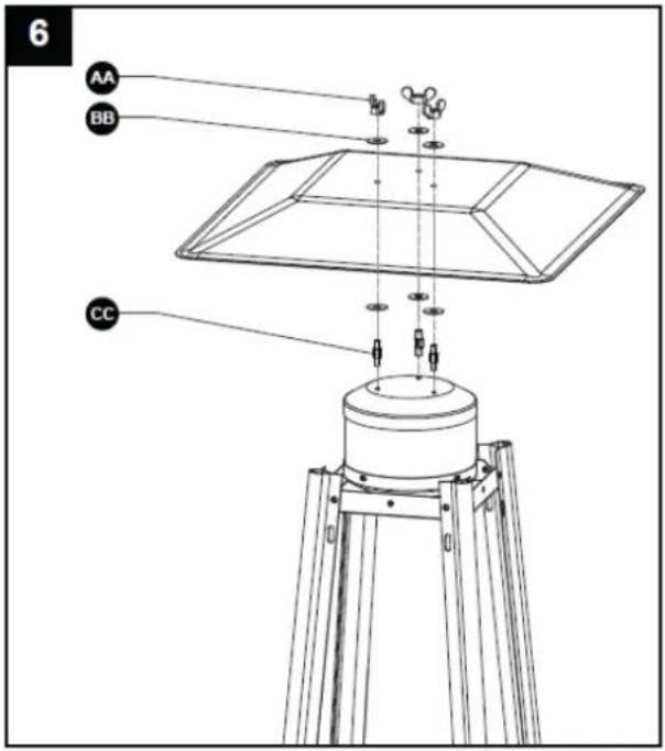
- Assemble the reflector onto the flame screen.
Screw the 3pcs stud on the flame screen, put 3pcs washer Φ6 onto the top of stud, then put the reflector onto the stud, secure them with 3pcs washer Φ6 and 3pcs wing nut.
Hardware Used

Wing nut
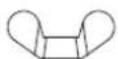
× 3

Washer Φ6

×6

Stud
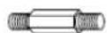
× 3
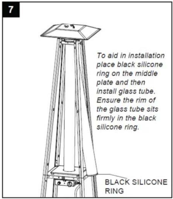
- Carefully install the glass tube by lifting up and inserting through the center hole in the upper plate. Ensure the black silicone ring is attached to the lower edge of the glass tube as illustrated. Slide the glass tube through the hole of the lower plate cover and onto the middle plate. Check and ensure that the glass tube is positioned properly and is completely covering the center hole of the middle plate.
WARNING! The black silicone ring must be in place prior to operating the heater.
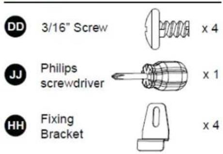
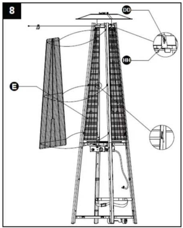
- Assembly the protective guard. Hang the hooks of the protective guard onto the holes in supports. Secure the protective guards with fixing brackets with 4pcs 3/16" screws.
Hardware Used
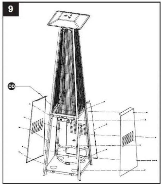
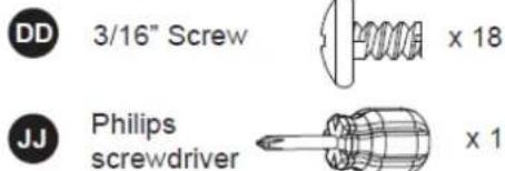
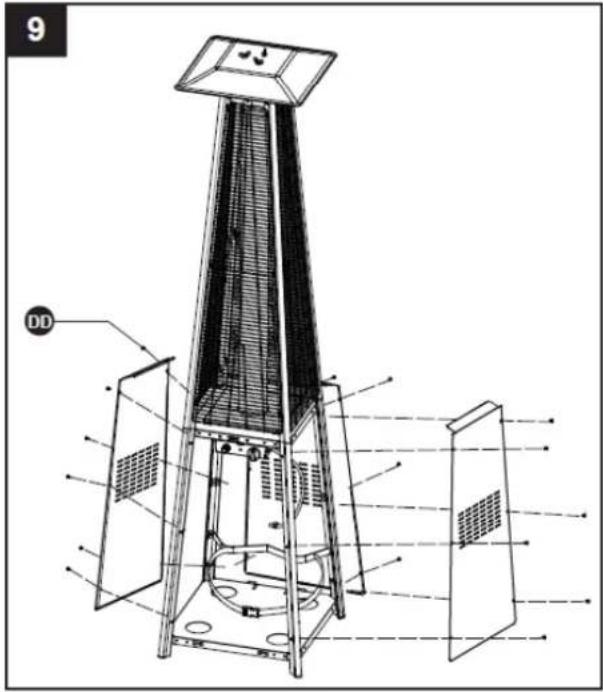
- Attach the three side panels to the heater using 18pcs screw 3/16".
Note : Do not cover the front side where the control knob is.
Hardware Used
- Install the knob to M4X6 screw. Hang the chain to the hole on the control box assy and put the pothook of front panel to the holes of bottom plate.
Hardware Used
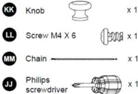
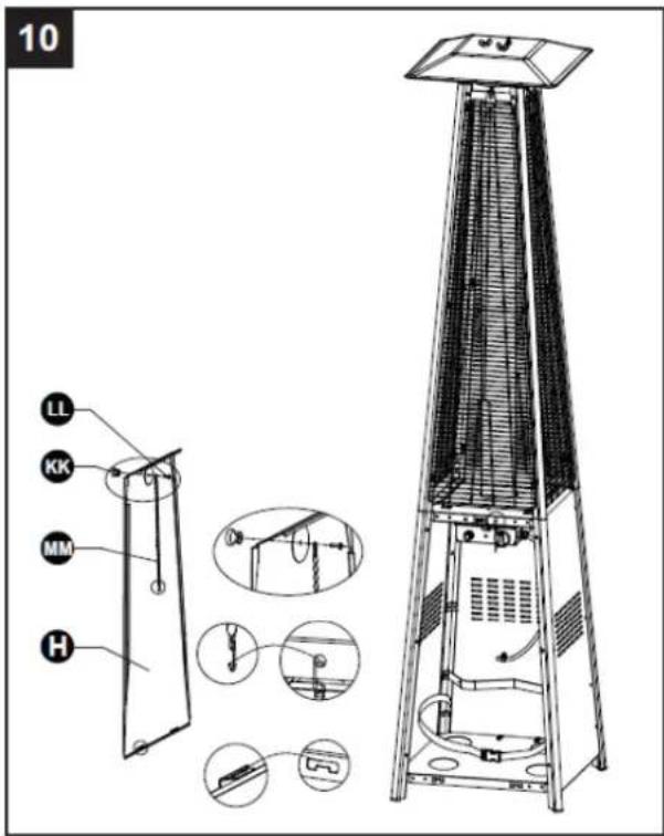
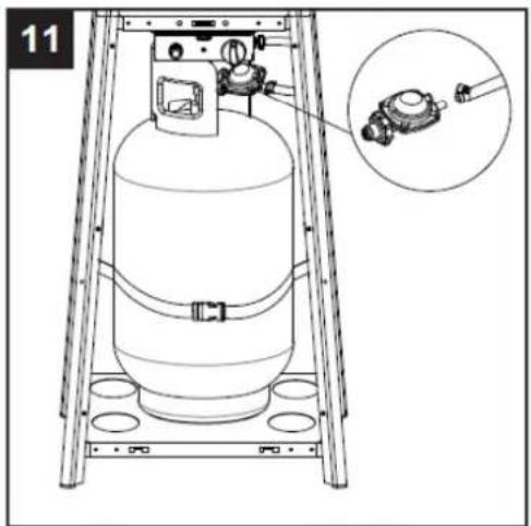
- Connect the gas hose and regulator after that connect the regulator to the gas cylinder.

WARNING! Ensure the hose does not contact any high temperature surfaces, or it may melt and leak causing a fire.
After the cylinder is placed inside the heater, secure the cylinder with block belt tightly.
natural_image
Technical line drawing of a gas cylinder mounted on a ladder, with an inset showing a close-up of the cylinder (no text or symbols present)12. Leak Check
WARNING! A leak test must be performed annually and each time a cylinder is hooked up or if a part of the gas system is replaced.
WARNING! Never use an open flame to check for gas leaks. Be certain no sparks or open flames are in the area while you check for leaks. Sparks or open flames will result in a fire or explosion, damage to property, serious bodily injury, or death.
Leak testing: This must be done before initial use, annually,and whenever any gas
Components are replaced or serviced. Do not smoke while performing this test, and remove all sources of ignition. See Leak Testing
Diagram for areas to check. Turn all burner controls to the off position. Turn gas supply valve on.
Brush a half-and-half solution of liquid soap and water onto all joints and connections of the regulator, hose, manifolds and valves.
Bubbles will indicate a gas leak. Either tighten the loose joint or have the part replaced with one recommended by the Customer Care department and have the patio heater inspected by a certified gas installer.
If the leak cannot be stopped, immediately shut off the gas supply, disconnect it, and have the patio heater inspected by a certified gas installer or dealer. Do not use the patio heater until the leak has been corrected.
natural_image
Technical line drawing of a mechanical component with no visible text or symbolsHose / Regulator connection
natural_image
Technical line drawing of a mechanical assembly with two components and curved components (no text or symbols)Regulator / Cylinder connection
12
PROBLEMS CHECK LIST
| PROBLEM | PROBABLE CAUSE | SOLUTION |
| Pilot will not light | Gas valve may be OFF | Turn the gas valve ON |
| Tank fuel empty | Refill LPG tank | |
| Opening blocked | Clean or replace opening | |
| Air in supply system | Purge air from lines | |
| Loose connections | Check all fittings | |
| Pilot will not stay on | Debris around pilot | Clean dirty area |
| Loose connections | Tighten connections | |
| Thermocouple bad | Replace thermocouple | |
| Gas leak in line | Check connections | |
| Lack of fuel pressure | Tank near empty. Refill LPG tank. | |
| Burner will not light | Pressure is low | Tank near empty. Refill LPG tank. |
| Opening blocked | Remove and clean | |
| Control not ON | Turn valve to ON | |
| Thermocouple bad | Replace thermocouple | |
| Pilot light assembly bent | Place pilot properly | |
| Not in correct location | Position properly and retry |
If the appliance is in case of any defaults or problems of assembly or use, please don't try to modify it by yourself, contact your supplier or distributor to solve it.
SERVICE
WARNING! If, despite compliance with the specified rules, device is not working properly, inform the manufacturer's authorized service centre.
The current list of service points can be found at: www.ravanson.pl Service is provided by the Quadra-Net network, please visit: www.quadra-net.pl And the helpline number: 61 853 44 44
- NAJCZĘSTSZE PROBLEMY
- GENERAL SAFETY INSTRUCTIONS
- FOR YOUR SAFETY
- WARNING
- CAUTION PLEASE READ CAREFULLY THE FOLLOWING SAFETY GUIDELINES BEFORE OPERATION.
- PLEASE NOTE!
- HEATER STAND AND LOCATION
- GAS REQUIREMENTS
- LEAKAGE TEST
- TO TURN OFF THE HEATER
- Storage
- CLEANING AND CARE
- Construction and characteristics
- Specifications
- Table of injector
- REGULATOR AND HOSE
- ASSEMBLY PARTS
- ASSEMBLY PROCEDURES
- Hardware Used
- Leak Check
- SERVICE
Brand : Ravanson
Model : OG-300
Category : Heating