
WS760T - Computer ASUS - Free user manual and instructions
Find the device manual for free WS760T ASUS in PDF.
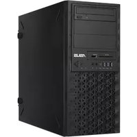


| Product Type | Workstation (ASUS E500 G9) |
| Dimensions (H x W x D) | 423 mm x 190 mm x 435 mm (16.7" x 7.48" x 17.1") |
| Net Weight | 9.9 kg (excluding CPU, DRAM, HDD) |
| Power Supply Options | 300W Bronze, 550W Gold, 750W Gold, 1000W Gold (ATX) |
| Supported Processors | Intel 12th/13th Gen Core i3/i5/i7/i9 (LGA1700) |
| Chipset | Intel W680 (supports Intel vPro) |
| Memory Type | DDR5 ECC/non-ECC UDIMM, up to 128GB (4 slots) |
| Expansion Slots | 5 PCIe slots (including PCIe 5.0 x16, PCIe 4.0 x16, etc.) |
| M.2 Storage | 3 M.2 slots (PCIe Gen4/Gen3) + 1 M.2 for WiFi |
| Storage Bays | 3 x 3.5" internal + 1 x 2.5" internal + 2 x 5.25" media bays |
| Networking | 2 x Intel I225-LM 2.5GbE LAN |
| Audio | Realtek ALC897 7.1-channel HD Audio |
| Front I/O | 1x USB 3.2 Gen 2x2, 2x USB 3.2 Gen 1, 1x USB 2.0, headphone/mic jacks |
| Rear I/O | 2x USB 3.2 Gen 2 (1 Type-A, 1 Type-C), 4x USB 3.2 Gen 1, HDMI, DP, DVI-D, VGA, 2x LAN, audio jacks |
| Graphics Support | Integrated Intel UHD Graphics; up to 1 dedicated GPU card |
| Operating System Support | Windows 11 Pro for Workstation |
| Security Features | TPM 2.0, chassis intrusion sensor, password protection in BIOS |
| Chassis Type | Tower (mid-tower), side panel with security screws |
| Cooling System | 1 x 120mm system fan (rear), CPU fan included, optional M.2 fan |
| Power Supply Connectors | 24-pin ATX + 8-pin (or 4-pin) 12V |
| Regulatory Compliance | BSMI, CE, FCC, ENERGY STAR, RoHS |
Frequently Asked Questions - WS760T ASUS
User questions about WS760T ASUS
0 question about this device. Answer the ones you know or ask your own.
Ask a new question about this device
Download the instructions for your Computer in PDF format for free! Find your manual WS760T - ASUS and take your electronic device back in hand. On this page are published all the documents necessary for the use of your device. WS760T by ASUS.
USER MANUAL WS760T ASUS
Copyright © 2023 ASUSTeK COMPUTER INC. All Rights Reserved.
No part of this manual, including the products and software described in it, may be reproduced, transmitted, transcribed, stored in a retrieval system, or translated into any language in any form or by any means, except documentation kept by the purchaser for backup purposes, without the express written permission of ASUSTeK COMPUTER INC. ("ASUS").
ASUS provides this manual “as is” without warranty of any kind, either express or implied, including but not limited to the implied warranties or conditions of merchantability or fitness for a particular purpose. In no event shall ASUS, its directors, officers, employees, or agents be liable for any indirect, special, incidental, or consequential damages (including damages for loss of profits, loss of business, loss of use or data, interruption of business and the like), even if ASUS has been advised of the possibility of such damages arising from any defect or error in this manual or product.
Specifications and information contained in this manual are furnished for informational use only, and are subject to change at any time without notice, and should not be construed as a commitment by ASUS. ASUS assumes no responsibility or liability for any errors or inaccuracies that may appear in this manual, including the products and software described in it.
Product warranty or service will not be extended if: (1) the product is repaired, modified or altered, unless such repair, modification of alteration is authorized in writing by ASUS; or (2) the serial number of the product is defaced or missing.
Products and corporate names appearing in this manual may or may not be registered trademarks or copyrights of their respective companies, and are used only for identification or explanation and to the owners' benefit, without intent to infringe.
Contents
Safety information......vi
Electrical Safety....vi
Operation Safety ......vi
About this guide....vii
Chapter 1: Product Introduction
1.1 System package contents....1-2
1.2 Serial number label....1-2
1.3 E500 G9 specifications summary....1-3
1.4 Front panel features....1-6
1.5 Rear panel features....1-7
1.6 Internal features....1-8
1.7 LED information 1-9
1.7.1 Front panel LEDs 1-9
1.7.2 Rear panel LEDs....1-10
Chapter 2: Hardware Setup
2.1 Chassis cover....2-2
2.1.1 Removing the side cover....2-2
2.2 CPU installation....2-4
2.3 Cooling system installation 2-7
2.4 System memory 2-9
2.4.1 Installing a DIMM on a single clip DIMM socket....2-11
2.5 Front panel cover 2-12
2.5.1 Removing the front panel cover 2-12
2.6 5.25-inch drives....2-13
2.7 Hard disk drives (HDD)....2-15
2.8 Expansion slots....2-19
2.8.1 Installing an expansion card....2-20
2.8.2 Configuring an expansion card 2-22
2.8.3 Installing M.2 (NGFF) cards....2-23
2.8.4 Installing an M.2 fan (optional)....2-26
2.9 System fan....2-28
2.10 BIOS update utility 2-29
2.11 Motherboard rear and audio connection 2-31
2.11.1 Rear I/O connection 2-31
2.11.2 Audio I/O connections....2-32
Contents
Chapter 3: Motherboard Information
3.1 Motherboard layout....3-2 3.2 Onboard buttons and switches 3-4 3.3 Jumpers 3-5 3.4 Onboard LEDs....3-7 3.5 Internal connectors....3-10
Chapter 4: BIOS Setup
4.1 Introduction to the BIOS....4-2 4.2 BIOS setup program 4-3
4.2.1 EZ Mode....4-4 4.2.2 Advanced Mode 4-5 4.2.3 Q-Fan Control 4-8
4.3 My Favorites 4-10 4.4 Main menu 4-12 4.5 Advanced menu 4-14
4.5.1 Platform Misc Configuration....4-15 4.5.2 CPU Configuration 4-16 4.5.3 System Agent (SA) Configuration 4-20 4.5.4 PCH Configuration 4-22 4.5.5 PCH Storage Configuration....4-23 4.5.6 PCH-FW Configuration 4-24 4.5.7 AMT Configuration 4-25 4.5.8 Thunderbolt(TM) Configuration....4-27 4.5.9 Serial Port Console Redirection....4-28 4.5.10 Intel TXT Information....4-31 4.5.11 PCI Subsystem Settings 4-31 4.5.12 USB Configuration 4-32 4.5.13 Network Stack Configuration....4-33 4.5.14 NVMe Configuration....4-33 4.5.15 HDD/SSD SMART Information 4-34 4.5.16 APM Configuration....4-34 4.5.17 Onboard Devices Configuration 4-35 4.5.18 Intel(R) Rapid Storage Technology....4-37
4.6 Monitor menu 4-38
4.7 Boot menu 4-46
Contents
4.8 Tool menu....4-52
4.8.1 ASUS EZ Flash 3 Utility 4-53 4.8.2 Secure Erase 4-53 4.8.3 ASUS User Profile....4-54 4.8.4 ASUS SPD Information 4-55 4.8.5 MemTest86 4-55
4.9 Exit menu 4-56
4.10 Updating BIOS....4-57
4.10.1 EZ Update....4-57 4.10.2 ASUS EZ Flash 3....4-58 4.10.3 ASUS CrashFree BIOS 3....4-59
Chapter 5: RAID Configuration
5.1 RAID configurations 5-2
5.1.1 RAID definitions 5-2 5.1.2 Installing storage devices....5-2 5.1.3 Creating a SATA RAID set in UEFI BIOS 5-3 5.1.4 Creating an NVMe RAID set with onboard M.2 modules in UEFI BIOS....5-6 5.1.5 Deleting a RAID set....5-10
5.2 Installing the RAID controller driver during Windows 10 or Windows 11 OS installation ....5-11
Appendix
W680/SYS block diagram A-2
Q-Code table....A-3
Notices ...... A-7
Warranty....A-20
Service and Support ...... A-22
Safety information
Electrical Safety
- Before installing or removing signal cables, ensure that the power cables for the system unit and all attached devices are unplugged.
- To prevent electrical shock hazard, disconnect the power cable from the electrical outlet before relocating the system.
- When adding or removing any additional devices to or from the system, contact a qualified service technician or your dealer. Ensure that the power cables for the devices are unplugged before the signal cables are connected. If possible, disconnect all power cables from the existing system before you service.
- If the power supply is broken, do not try to fix it by yourself. Contact a qualified service technician or your dealer.
Operation Safety
- Servicing of this product or units is to be performed by trained service personnel only.
- Before operating the server, carefully read all the manuals included with the server package.
- Before using the server, make sure all cables are correctly connected and the power cables are not damaged. If any damage is detected, contact your dealer as soon as possible.
- To avoid short circuits, keep paper clips, screws, and staples away from connectors, slots, sockets and circuitry.
- Avoid dust, humidity, and temperature extremes. Place the server on a stable surface.

This product is equipped with a three-wire power cable and plug for the user's safety. Use the power cable with a properly grounded electrical outlet to avoid electrical shock.
Lithium-Ion Battery Warning
CAUTION! Danger of explosion if battery is incorrectly replaced. Replace only with the same or equivalent type recommended by the manufacturer. Dispose of used batteries according to the manufacturer's instructions.

Heavy System
CAUTION! This server system is heavy. Ask for assistance when moving or carrying the system.
About this guide
Audience
This user guide is intended for system integrators, and experienced users with at least basic knowledge of configuring a server.
Contents
This guide contains the following parts:
1. Chapter 1: Product Introduction
This chapter describes the general features of the server, including sections on front panel and rear panel specifications.
2. Chapter 2: Hardware Setup
This chapter lists the hardware setup procedures that you have to perform when installing or removing system components.
3. Chapter 3: Motherboard Information
This chapter includes the motherboard layout and brief descriptions of the jumpers and internal connectors.
4. Chapter 4: BIOS Setup
This chapter tells how to change system settings through the BIOS Setup menus and describes the BIOS parameters.
5. Chapter 5: RAID Configuration
This chapter provides instructions for setting up, creating and configuring RAID sets using the available utilities.
Conventions used in this guide
To ensure that you perform certain tasks properly, take note of the following symbols used throughout this manual.

DANGER/WARNING: Information to prevent injury to yourself when trying to complete a task.

CAUTION: Information to prevent damage to the components when trying to complete a task.

IMPORTANT: Instructions that you MUST follow to complete a task.

NOTE: Tips and additional information to help you complete a task.
Typography
Bold text
Indicates a menu or an item to select.
Italics
Used to emphasize a word or a phrase.
Keys enclosed in the less-than and greater-than sign means
that you must press the enclosed key.
Example: means that you must press the Enter or Return key.
+ + If you must press two or more keys simultaneously, the key names are linked with a plus sign (+).
Example: + +
Command
Means that you must type the command exactly as shown, then supply the required item or value enclosed in brackets.
Example: At DOS prompt, type the command line:
format A:/S
References
Refer to the following sources for additional information, and for product and software updates.
ASUS websites
The ASUS websites provide updated information for all ASUS hardware and software products. Visit https://www.asus.com for more information.
Product Introduction
This chapter describes the general features of the server, including sections on front panel and rear panel specifications.
1
1.1 System package contents
Check your system package for the following items.
Model Name E500 G9
Accessories 1 x E500 G9 Support DVD
1 x AC Power Cable
1 x COM Port Cable
Optional Items Smart Card Reader
Antivirus CD Pack
Print Port Cable
DVD-RW
Keyboard and Mouse

If any of the above items is damaged or missing, contact your retailer.
1.2 Serial number label
Before requesting support from the ASUS Technical Support team, you must take note of the product's serial number containing 12 characters such as xxSxxxxxxxxx shown as the figure below. With the correct serial number of the product, ASUS Technical Support team members can then offer a quicker and satisfying solution to your problems.

1.3 E500 G9 specifications summary
The ASUS E500 G9 workstation features the ASUS W680/SYS motherboard.
| Processor / System Bus | 1 x Socket (LGA1700)Intel® 12thGeneration CoreTM i3/i5/i7/i9 ProcessorsIntel® 13thGeneration CoreTM i5/i7/i9 Processors* Please refer to www.asus.com for Intel® CPU support list. | |
| Core Logic | Intel® W680 Chipset(Supports Intel vPro®) | |
| Memory | Total Slots | 4 (2-channel per CPU, 4 DIMM per CPU) |
| Capacity | Maximum up to 128GB (UDIMM) | |
| Memory Type | DDR5 4400/3600 MHz, ECC/non-ECC UDIMM* Memory frequency support also depends on the CPU installed.Please refer to www.asus.com for latest memory AVL update. | |
| Memory Size | 32GB, 16GB, 8GB (UDIMM)* Please refer to www.asus.com for latest memory AVL update. | |
| Expansion Slots | Total PCI/PCI-X /PCIe Slots | 5 |
| Slot Type | Slot 1: PCIe x16 slot, Gen5 x16 or x8 Link, from CPU (shared with Slot 3, x8/x8)Slot 2: PCIe x1, Gen3 x1, from PCHSlot 3: PCIe x16 slot, Gen5 x8 Link, from CPUSlot 4: PCIe x16 slot, Gen4 x4 Link from PCHSlot 5: PCIe x16 slot, Gen3 x4 Link, from PCH | |
| M.2 | 1 x M.2 2280/2260/2242 PCIe Gen4 x4 ,from CPU1 x M.2 2280/2260/2242 PCIe Gen3 x4 ,from PCH1 x M.2 22110/2280/2260/2242 PCIe Gen4 x4 ,from PCH1 x M.2 2330 PCIe Gen3 x1 (for WIFI Module)(Supports Intel® Optane Memory) | |
| Disk Controller | SATA Controller | Intel® W680 Chipset:8 x SATA 6Gb/sIntel® RST (Windows)(Supports software RAID 0, 1, 10 & 5) |
| Storage Bays | Storage Bay | 3 x Internal 3.5" Storage Bays1 x Internal 2.5" Storage Bays |
| MB on-board Connectors | 3 x M.2 Connectors8 x SATA 7-pin Connectors | |
| Default Cable | 4 x SATA 6G Cables | |
(continued on the next page)
E500 G9 specifications summary
| Networking | 2 x Intel® I225-LM 2.5GbE LAN |
| VGA | CPU Integrated (Intel® UHD)Multi-VGA output support: DVI-D/HDMI TM /DisplayPort/VGA-Supports DVI-D with Max resolution 1920 x 1200@60 Hz-Supports HDMI TM 1.4 with Max resolution 4096 x 2160@24 Hz-Supports DisplayPort 1.4 with Max resolution 4096 x 2160@60 Hz-Supports VGA with Max resolution 1920 x 1200@60 Hz |
| Graphic | Up to 1 GPU Card |
| Audio | Realtek® ALC897 7.1-Channel High Definition Audio CODEC |
| Auxiliary Storage Device Bay (Floppy / Optical Drive) | 2 x 5.25” Media BaysODD/DVD-RW (optional) |
| Front I/O | 1 x USB 3.2 Gen 2x2 Port2 x USB 3.2 Gen 1 Ports1 x USB 2.0 Ports1 x Headphone Jack1 x Microphone Jack |
| Rear I/O | 2 x USB 3.2 Gen 2 Ports (1 x Type A Port, 1 x USB Type-C ® Port)4 x USB 3.2 Gen 1 Ports1 x HDMI TM Port1 x DisplayPort1 x DVI-D Port1 x VGA Port2 x LAN Ports (RJ-45)1 x 7.1-channel Audio I/O Ports (5+1 Audio Jacks) |
| Switch/LED | Front Switch/LED:1 x Power Switch/LED1 x Reset Switch1 x HDD Access LED |
| Security Options | Trusted Platform Module (TPM 2.0) |
| Other Options | LPT Port |
(continued on the next page)
E500 G9 specifications summary
| OS Support | Windows® 11 Pro for Workstation* Refer to https://www.asus.com/event/Server/OS_support_list/OS.html for the latest OS support. |
| Management Software | ASUS Control Center support |
| Regulatory Compliance | BSMI, CE, FCC, ENERGY STAR® |
| Dimension (HH x WW x DD) | 423 mm x 190 mm x 435 mm16.7" x 7.48" x 17.1" |
| Net Weight | 9.9 Kg(excluding CPU, DRAM, and HDD) |
| Gross Weight | 12.1 Kg(including packaging, excluding CPU, DRAM, and HDD) |
| Power Supply and Rating | 300W Bronze ATX Power Supply(100-127/220-240Vac, 6-3A, 50-60Hz, Class I)550W Gold ATX Power Supply(100-240Vac, 9-4.5A, 50-60Hz)750W Gold ATX Power Supply(100-240Vac, 9-4.5A, 50/60Hz)1000W ASUS/TUF-GAMING-1000G ATX Power Supply(100-240Vac, 15-8A, 47/63Hz) |
| Environment | Operating temperature: 10°C ~ 35°CNon-operating temperature: -40°C ~ 70°CNon-operating humidity: 20% ~ 90% (Non-condensing) |

Specifications are subject to change without notice.
1.4 Front panel features

1.5 Rear panel features

1.6 Internal features
The ASUS E500 G9 workstation includes the basic components as shown:

- Power supply unit
- 120 mm x 120 mm system fan
- ASUS W680/SYS motherboard
- Expansion card locks
- Optical drive (Optional)
- 1 x 5.25-inch drive bay
- Front I/O board (hidden)
- 3 x 3.5-inch Internal storage bays
- 1 x 2.5-inch Internal storage bay

Turn off the system power and detach the power supply before removing or replacing any system component.

The barebone server does not include a floppy disk drive. If you need to use a floppy disk, connect the USB floppy disk drive to any of the USB ports on the front or rear panel.
WARNING
HAZARDOUS MOVING PARTS
KEEP FINGERS AND OTHER BODY PARTS AWAY
1.7 LED information
1.7.1 Front panel LEDs

| LED Icon Display status Description | |||
| HDD Access LED | OFF | No activity | |
| Blinking | Storage device reading or writing data | ||
1.7.2 Rear panel LEDs

Intel® I225-LM 2.5G LAN ports LED indications
| Activity Link LED Speed LED | |||
| Status Description Status Description | |||
| Off | No link Off 10/100 Mbps connection | ||
| Green | Linked Orange 1 Gbps connection | ||
| Green (Blinking) | Data activity Green 2.5 Gbps connection | ||
| Green (Blinking then steady) | Ready to wake up from S5 mode | ||

You can disable the LAN controllers in BIOS. Due to hardware design, the LAN1 port's LEDs may continue to blink even when disabled.
Hardware Setup
This chapter lists the hardware setup procedures that you have to perform when installing system components. It includes description of the jumpers and connectors on the motherboard.
2
2.1 Chassis cover
2.1.1 Removing the side cover

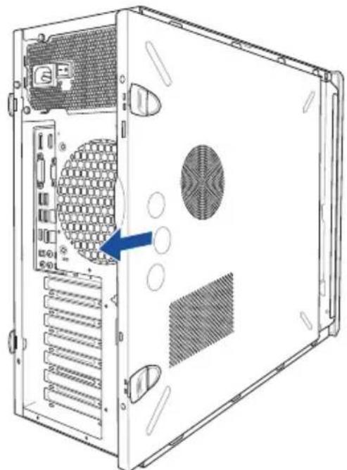
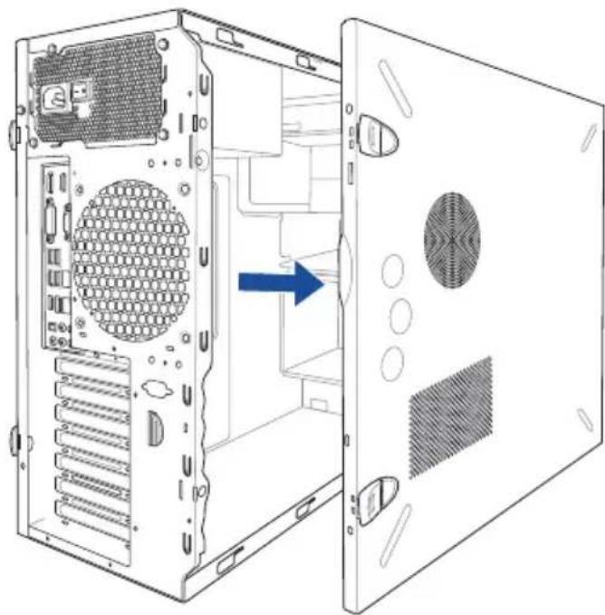
- Ensure that you unplug the power cord before removing the side cover. • Take extra care when removing the side cover. Keep your fingers from components inside the chassis that can cause injury, such as the CPU fan, rear fan, and other sharp-edged parts.
- The images of the system shown in this section are for reference purposes only and may not exactly match the model you purchase.
To remove the side cover:
- Remove the two screws that secure the side cover.

- Press the side cover locks outward.

- Slightly pull the side cover toward the rear just enough to detach it from the chassis.
- Remove the cover and set it aside.
2.2 CPU installation
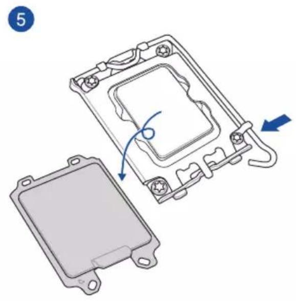
The motherboard comes with a surface mount LGA1700 socket for Intel® 12th Generation Core™ i3/i5/i7/i9 and Intel® 13th Generation Core™ i5/i7/i9 processors.

W680/SYS CPU LGA1700

Ensure that you install the correct CPU designed for LGA1700 socket only. DO NOT install a CPU designed for other sockets on the LGA1700 socket.

- Ensure that all power cables are unplugged before installing the CPU.
- Upon purchase of the motherboard, ensure that the PnP cap is on the socket and the socket contacts are not bent. Contact your retailer immediately if the PnP cap is missing, or if you see any damage to the PnP cap/socket contacts/motherboard components. ASUS will shoulder the cost of repair only if the damage is shipment/transit-related.
- Keep the cap after installing the motherboard. ASUS will process Return Merchandise Authorization (RMA) requests only if the motherboard comes with the cap on the socket.
- The product warranty does not cover damage to the socket contacts resulting from incorrect CPU installation/removal, or misplacement/loss/incorrect removal of the PnP cap.

1

Take caution when lifting the load lever, ensure to hold onto the load lever when releasing the load lever. Letting go of the load lever immediately after releasing it may cause the load lever to spring back and cause damage to your motherboard.
2
3

2.3 Cooling system installation

Apply the Thermal Interface Material to the CPU heatsink and CPU before you install the heatsink and fan, if necessary.
CPU heatsink and fan assembly for 65W


A screwdriver with a torque value of 4.5 ± 0.5 kgf-cm is recommended.
CPU heatsink and fan assembly for 125W


2.4 System memory
The motherboard comes with four DDR5 (Double Data Rate 5) Dual Inline Memory Modules (DIMM) slots.

A DDR5 module is notched differently from a DDR, DDR2, DDR3, or DDR4 module. DO NOT install a DDR, DDR2, DDR3, or DDR4 memory module to the DDR5 slot.

W680/SYS 288-pin DDR5 DIMM sockets
Recommended memory configurations

DIMM configuration
| A1 A2 B1 B2 | ||||
| 1 DIMM • | ||||
| 2 DIMMs •• | ||||
| 4 DIMMs • • • • | ||||
Memory configurations
You may install 8 GB, 16 GB, and 32 GB unbuffered DDR5 DIMMs into the DIMM sockets.

You may install varying memory sizes in Channel A and Channel B. The system maps the total size of the lower-sized channel for the dual-channel configuration. Any excess memory from the higher-sized channel is then mapped for single-channel operation.

- The default memory operation frequency is dependent on its Serial Presence Detect (SPD), which is the standard way of accessing information from a memory module. Under the default state, some memory modules for overclocking may operate at a lower frequency than the vendor-marked value.
- For system stability, use a more efficient memory cooling system to support a full memory load (4 DIMMs) or overclocking condition.
- Always install the DIMMs with the same CAS Latency. For optimum compatibility, we recommend that you install memory modules of the same version or data code (D/C) from the same vendor. Check with the vendor to get the correct memory modules.
- Visit the ASUS website for the latest QVL.
2.4.1 Installing a DIMM on a single clip DIMM socket
- Unlock a DIMM socket by pressing the retaining clip outward.
- Align a DIMM on the socket such that the notch on the DIMM matches the DIMM slot key on the socket.


A DIMM is keyed with a notch so that it fits in only one direction. DO NOT force a DIMM into a socket in the wrong direction to avoid damaging the DIMM.
- Hold the DIMM by both of its ends then insert the DIMM vertically into the socket. Apply force to both ends of the DIMM simultaneously until the retaining clip snaps back into place and the DIMM cannot be pushed in any further to ensure proper sitting of the DIMM.


Always insert the DIMM into the socket vertically to prevent DIMM notch damage.

- To install two or more DIMMs, refer to the user guide bundled in the motherboard package. • Refer to the ASUS website for qualified vendor lists of the memory modules.
Removing a DIMM from a single clip DIMM socket
- Press the retaining clip outward to unlock the DIMM.
- Remove the DIMM from the socket.


Support the DIMM lightly with your fingers when pressing the retaining clips. The DIMM might get damaged when it flips out with extra force.
2.5 Front panel cover
Before you can install a 5.25-inch drive, you should first remove the front panel cover.

Ensure to unplug the power cable before installing or removing any system components. Failure to do so may cause damage to the motherboard and other system components!
2.5.1 Removing the front panel cover
To remove the front panel cover:
- Locate the front panel assembly lock then slide it outward to unlock the latches that secure the front panel cover to the chassis.

- Remove the front panel assembly from the chassis and set it aside.

2.6 5.25-inch drives
This system comes with three 5.25-inch drive bays located on the upper front section of the chassis.

If your system came with an optical drive, the optical drive occupies the topmost bay (1). The lower bays (2 and 3) are available for additional 5.25-inch optical, zip, or floppy disk drives.

Installing a 5.25-inch drive
To install a 5.25-inch drive:
- Remove the front panel cover. Refer to the Removing the front panel cover section for more information.
- Pull the bay locks outward.

- Remove the metal cover of the bay you intend to use.

Take extra care when removing the metal cover. Use tools such as a screwdriver to bend and remove the metal cover to avoid physical injury.

- Prepare the 5.25-inch drive.
- Insert and carefully push the drive into the bay until its screw holes align with the holes on the bay.

- Push the bay locks to secure the drive in place.

- Connect the SATA cable to the SATA connector of the drive.
- Connect a SATA power cable from the power supply to the power connector of the drive.
- Reinstall the front panel cover.

SATA cable / SATA power cable
2.7 Hard disk drives (HDD)
The server system supports three (3) 3.5-inch Serial ATA hard disk drives via the hard disk drive bays and one 2.5-inch HDD/SSD drive at the bottom of the HDD cage.
Installing 3.5-inch HDDs
To install 3.5-inch Serial ATA hard disk drives:
- Remove the side cover of the chassis. Refer to the "Removing the side cover" section for more information.
- Prepare the 3.5-inch HDD and the bundled set of screws.
- Locate the HDD cage lock, press it up (A), then swing the HDD cage outwards (B) until it clicks in place.

- Align and insert the 3.5-inch HDD into the drive bay ensuring that the screw holes on the HDD match the screw holes on the HDD cage.

- Secure the 3.5-inch HDD to the HDD cage using the bundled set of screws.

- Swing the HDD cage inwards until it clicks back into place.
- Connect the SATA cable and SATA power cable to the 3.5-inch HDD.

Installing 2.5-inch HDD/SSD
To install a 2.5-inch HDD/SSD:
- Remove the side cover of the chassis. Refer to the "Removing the side cover" section for more information.
- Prepare the 2.5-inch HDD/SSD and the bundled set of screws.
- Lay the system on its side on a flat and stable surface.
- Locate the HDD cage lock, press it up (A), then swing the HDD cage outwards (B).
- Align and insert the 2.5-inch HDD/SSD into the drive bay as shown. Push it all the way until its screw holes align with the holes on the drive bay.

- Secure the 2.5-inch HDD/SSD to the HDD cage using the bundled set of screws.

- Swing the HDD cage inwards until it clicks back into place.
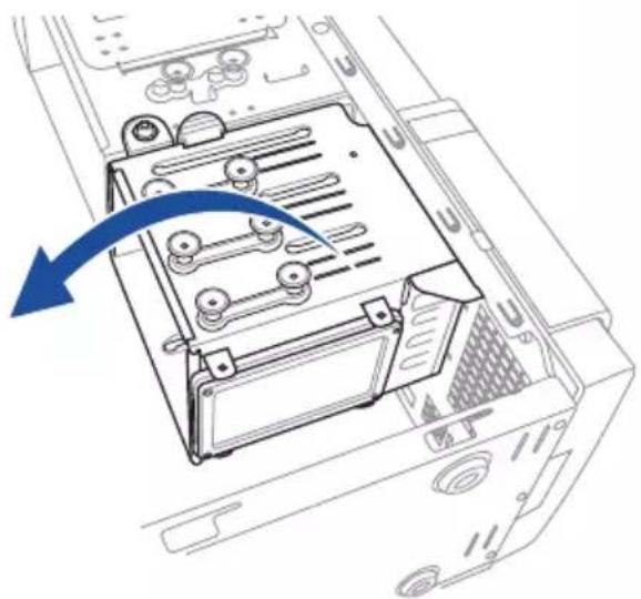
- Connect a SATA cable and a SATA power cable to the 2.5-inch HDD/SSD.

2.8 Expansion slots

Unplug the power cord before adding or removing expansion cards. Failure to do so may cause you physical injury and damage motherboard components.
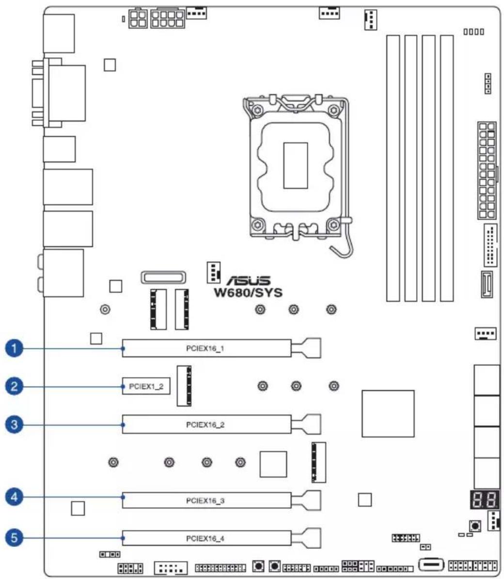
| Slot No. Slot Description |
| 1 PCIE x16_1 slot |
| 2 PCIE x1_2 slot |
| 3 PCIE x16_2 slot |
| 4 PCIE x16_3 slot |
| 5 PCIE x16_4 slot |
2.8.1 Installing an expansion card
To install an expansion card:
- Lay the system on its side on a flat, stable surface.
- Press the PCIe latch (A), hold it by its edge then lift it towards the rear (B).

- Remove the screw (A) that secures the metal bracket to the chassis then remove the metal bracket (B).
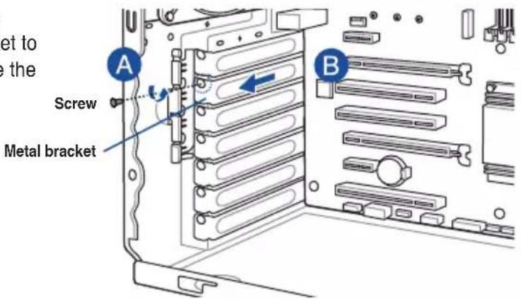
- Align and insert the expansion card into the PCIe slot.
PCIe slotExpansion card

- Lift the PCIe latch inwards until it clicks into place securing the expansion card to the chassis.

- (Optional) Replace the screw of the metal bracket.

2.8.2 Configuring an expansion card
| VGA configuration | PCI Express operating mode | ||
| PCIe 5.0 x16_1 (gray) PCIe 5.0 x16_2 PCIe 4.0 x16_3 | |||
| Single VGA/PCIe card | x16 (Recommended for single VGA card) | N/A N/A | |
| Dual VGA/PCIe cards | x8 x8 N/A | ||
| Triple VGA/PCIe cards | x8 x8 x4 | ||

- In single VGA card mode, use the PCIe 5.0 x16_1 slot for a PCI Express x16 graphics card to get better performance.
- We recommend that you provide sufficient power when running CrossFireX™ mode.
- Connect a chassis fan to the motherboard connector labeled CHA_FAN1 when using multiple graphics cards for better thermal environment.
- Connect the M.2_1 heatsink fan to the motherboard connector labeled CHA_FAN2.
2.8.3 Installing M.2 (NGFF) cards
To install an M.2 card:
- Locate the M.2 connector (M.2(SOCKET3)) on the motherboard.

W680/SYS M.2 socket
- Completely loosen the screws on the heatsink.
- Remove the heatsinks.

- Remove the screw on the stand screw.


Please pay attention when removing the screw, the stand screw might be removed together with it.
- (optional) Remove the stand screw, then secure it to the screw hole of the M.2 card length you wish to install an M.2 to.
- Align and insert the M.2 card into the M.2 connector (M.2(SOCKET3)).

- Secure the M.2 card with the screw you removed in step 4.


Ensure that the M.2 card is positioned between the screw and the stand screw before securing it.
- Repeat steps 4 to 7 to install an M.2 to another M.2 connector.
- (optional) Secure the bundled fan to the M.2_1 heatsink using the four (4) bundled M.2 heatsink screws and screw stands.

- Remove the plastic film from the thermal pads on the bottom of the heatsinks.
- Replace the heatsinks.
- Secure the heatsinks using the screws previously loosened.

- (optional) Connect the M.2_1 heatsink fan to the CHA_FAN2 connector on your motherboard if you installed the M.2 heatsink fan in step 9.
2.8.4 Installing an M.2 fan (optional)

The M.2 fan is required if more than two (2) M.2 cards are installed in the system.


M5.0 X 8.0L Fan Screws x4


M2.0 X 5.0L Support Bracket Screws x7


M2.0 X 5.0L Chassis Screws x7
To install the M.2 fan and support bracket:
- Install and secure the support bracket base using two (2) chassis screws.

- Align and install the support bracket, then secure it using three (3) chassis screws.

- Install and secure the backplate mounts using six (6) support bracket screws.


Install the backplate mounts in order from top to bottom. The bottom-most backplate mount should be installed last.
Secure the M.2 fan to the fan backplate using four (4) fan screws.

- Align and install the fan backplate, secure it using one (1) support bracket screw and two (2) chassis screws, then connect the fan cable to the CHA_FAN3 connector on the motherboard.


Follow the previous instructions in reverse order if you want to uninstall the M.2 fan.
2.9 System fan
This section describes how to remove the system fan in the event that you need to install or remove previously installed or new system components, or when the system fan needs to be replaced because it was damaged or became defective.
To remove the system fan:
- Disconnect the system fan cable from the CHA_FAN1 connector on the motherboard.

- Remove the four system fan screws at the rear panel. Keep the screws for later use.

Hold the system fan with one hand while removing the system fan screws.
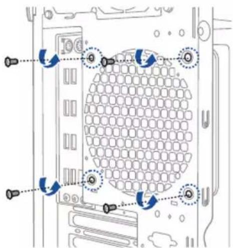
- Remove the system fan.

Follow the previous instructions in reverse order if you want to reinstall the system fan.

2.10 BIOS update utility
USB BIOS FlashBack™
USB BIOS FlashBack™ allows you to easily update the BIOS without entering a bootable environment, ideal for BIOS recovery, rollback, or updates to support new CPUs. Simply insert a USB storage device to the USB port (the USB port is marked on the I/O shield) then press the USB BIOS FlashBack™ button for three seconds to start the update process.
To use USB BIOS FlashBack™:
- Download the latest BIOS from the support site at www.asus.com/support/ and save it to a USB storage device.

- We recommend you to use a USB 2.0 storage device to save the latest BIOS version for better compatibility and stability.
- When downloading or updating the BIOS file, rename it as W680S.CAP for this motherboard.
- Insert the USB storage device to the USB FlashBack™ port.
- Shut down your computer.
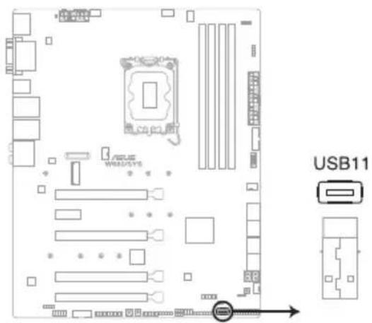
- On your motherboard, press the BIOS FlashBack™ button for three seconds until the FlashBack™ LED blinks three times, indicating that the BIOS FlashBack™ function is enabled.
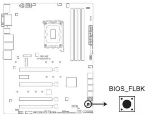
W680/SYS BIOS_FLBK button
- Wait until the light goes out, indicating that the BIOS updating process is completed.

For more BIOS update utilities in BIOS setup, refer to the section Updating BIOS in Chapter 4.

- Do not unplug portable disk, power system, or short the CLRTC header while BIOS update is ongoing, otherwise update will be interrupted. In case of interruption, please press and hold the BIOS_FLBK button for 3 seconds again to restart the process.
- If the light flashes for five seconds and then turns into a solid light, this means that the BIOS FlashBack™ is not operating properly. Please check the following when this happens:
- The USB drive should only contain a single partition.
- The USB drive should be formatted to a FAT32, FAT16, or NTFS filesystem.
- The BIOS filename should be correctly named, and in the root folder of the USB drive.
- If the problem persists, the USB drive may not be compatible, please try another USB drive of a different brand/model. Then retry the flashback by pressing the BIOS FlashBack™ button for three seconds until the FlashBack™ LED starts to blink.
2.11 Motherboard rear and audio connection
2.11.1 Rear I/O connection

Rear panel connectors
| 1. DisplayPort 7. USB 3.2 Gen 1 ports 3 and 4 | |
| 2. VGA port 8. USB 3.2 Gen 2 Type-C | ® port C1 |
| 3. USB 3.2 Gen 1 ports 5 and 6 9. USB 3.2 | Gen 2 port |
| 4. Intel ® LAN I225-LM ports 10. Optical S/PDIF | Out port |
| 5. HDMITM port 11. Audio I/O ports* | |
| 6. DVI-D port |
* : Refer to the table below for audio port definitions.
* Audio 2, 4, 5.1 or 7.1-channel configuration
| Port | Headset / 2-channel | 4-channel 5.1-channel 7.1-channel | ||
| Light Blue Line In Line In Line In Side Speaker Out | ||||
| Lime | Line Out | Front Speaker Out | Front Speaker Out | Front Speaker Out |
| Pink | Mic In | Mic In Mic In Mic In | ||
| Orange | - | - | Center/Sub woofer | Center/Sub woofer |
| Black | - | Rear Speaker Out | Rear Speaker Out | Rear Speaker Out |
2.11.2 Audio I/O connections
Audio I/O ports
Connect to Headphone and Mic
Connect to Stereo Speakers![graph TD A["AUDIO INPUTS"] --> B["Output Module 1"] A --> C["Output Module 2"]](/content/2026/05/981869/images/2123cd6149e1c841301be4048af2e55cba252a78c8a6ac2300602c6b5e92f666.jpg)
Connect to 2-channel Speakers![graph TD A["Audio INPUTS"] --> B["Device 1"] A --> C["Device 2"] A --> D["Device 3"] A --> E["Device 4"] A --> F["Device 5"]](/content/2026/05/981869/images/00e73c1b5ba50ceee735940ffb5929ce614d199acd3cd06b92c19ccc467cd9ba.jpg)
Connect to 4-channel Speakers![graph TD A["Audio Inputs"] --> B["Rear"] C["Audio Inputs"] --> D["Front"] E["Display Unit 1"] --> F["Speaker 1"] G["Display Unit 2"] --> H["Speaker 2"] I["Display Unit 3"] --> J["Speaker 3"]](/content/2026/05/981869/images/5a5aef59ce2d52bd45814a7f478e60ef4bf0052dbad26d94e88282591df73bfd.jpg)
Connect to 5.1-channel Speakers![graph TD A["Audio Inputs"] --> B["Rear"] A --> C["Front"] A --> D["Center/Subwoofer"] E["Output Port"] --> F["Device 1"] E --> G["Device 2"] E --> H["Device 3"]](/content/2026/05/981869/images/4b88c9495aed30d7c9ccc18758411ee651b33f3b394a9d07f616080a9112bff2.jpg)
Connect to 7.1-channel Speakers![graph TD A["Speaker 1"] --> B["Subwoofer"] C["Speaker 2"] --> B D["Speaker 3"] --> B E["Speaker 4"] --> B F["Speaker 5"] --> B G["Speaker 6"] --> B H["Speaker 7"] --> B I["Speaker 8"] --> B J["Speaker 9"] --> B K["Speaker 10"] --> B L["Speaker 11"] --> B M["Speaker 12"] --> B N["Speaker 13"] --> B O…](/content/2026/05/981869/images/4e257733a3f5da33b32c8507b330378b5f8df58911f4d7dca37aaf74f2861701.jpg)
Motherboard Information
3
This chapter includes the motherboard layout and brief descriptions of the jumpers and internal connectors.
3.1 Motherboard layout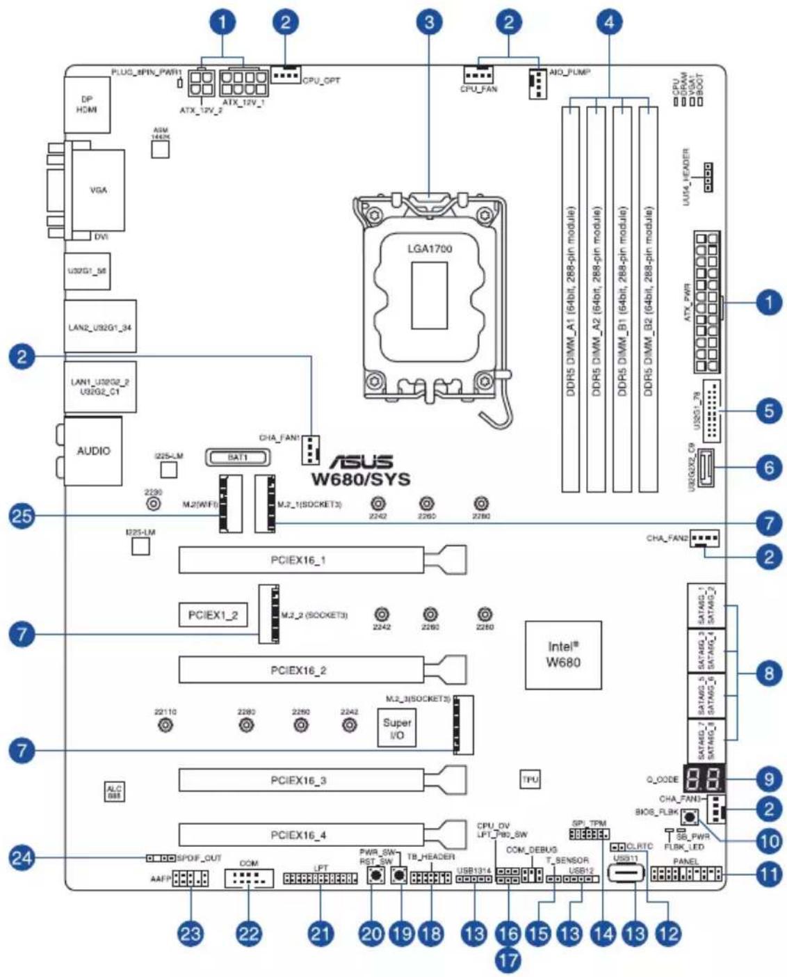
| Layout contents Page | |
| 1. ATX power connectors 3-16 | |
| 2. Fan connectors 3-14 | |
| 3. CPU socket 2-4 | |
| 4. DIMM slots 2-8 | |
| 5. USB 3.2 Gen 1 connector 3-12 | |
| 6. USB 3.2 Gen 2x2 Type-C ® Front Panel connector 3-12 | |
| 7. M.2 sockets 3-17 | |
| 8. Intel ® Serial ATA 6 Gb/s connectors 3-10 | |
| 9. Q-Code LED 3-8 | |
| 10. BIOS FlashBack TM button 2-24 | |
| 11. System Panel connector 3-15 | |
| 12. Clear RTC RAM header 3-5 | |
| 13. USB 2.0 connectors 3-13 | |
| 14. TPM connector 3-11 | |
| 15. Thermal Sensor connector | 3-19 |
| 16. CPU Over Voltage jumper | 3-6 |
| 17. LPT and Q-Code jumper | 3-6 |
| 18. Thunderbolt TM connector | 3-19 |
| 19. Power-on button | 3-4 |
| 20. Reset button | 3-4 |
| 21. LPT connector | 3-18 |
| 22. Serial Port connector | 3-13 |
| 23. Front Panel Audio connector | 3-11 |
| 24. Digital Audio connector | 3-14 |
| 25. M.2 slot (Key E) | 3-18 |
3.2 Onboard buttons and switches
Onboard buttons and switches allow you to fine-tune performance when working on a bare or open-case system. This is ideal for overclockers and gamers who continually change settings to enhance system performance.
1. Power-on button
The motherboard comes with a power-on button that allows you to power up or wake up the system. The button also lights up when the system is plugged to a power source indicating that you should shut down the system and unplug the power cable before removing or installing any motherboard component.

2. Reset button
Press the reset button to reboot the system.

3.3 Jumpers
1. Clear RTC RAM header
This header allows you to clear the Real Time Clock (RTC) RAM in CMOS. You can clear the CMOS memory of date and system setup parameters by erasing the CMOS RTC RAM data. The onboard button cell battery powers the RAM data in CMOS, which includes system setup information such as system passwords.
To erase the RTC RAM:
- Turn OFF the computer and unplug the power cord.
- Use a metal object such as a screwdriver to short the two pins.
- Plug the power cord and turn ON the computer.
- Hold down the key during the boot process and enter BIOS setup to re-enter data.

Except when clearing the RTC RAM, never short-circuit the CLRTC header. Shorting the CLRTC header will cause system boot failure!

If the steps above do not help, remove the onboard battery and short the two pins again to clear the CMOS RTC RAM data. After clearing the CMOS, reinstall the battery.

W680/SYS Clear RTC RAM
2. LPT and Q-Code jumper
This jumper allows you to enable either LPT (Line Printing Thermal) connector or Q-Code at a time.

To switch between LPT and Q-Code:
- Turn OFF the computer and unplug the power cord.
- Move the jumper cap to switch between LPT and Q-Code.
- Plug the power cord and turn ON the computer.
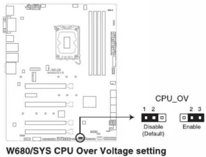
3. CPU Over Voltage jumper
The CPU Over Voltage jumper allows you to set a higher CPU voltage for a flexible overclocking system (depending on the type of the installed CPU). Set to pins 2-3 to increase the CPU voltage setting, or set to pins 1-2 to use the default CPU voltage setting.
3.4 Onboard LEDs
1. Q LED (CPU, DRAM, VGA, BOOT)
Q LED checks key components (CPU, DRAM, VGA card, and booting devices) in sequence during motherboard booting process. If an error is found, the corresponding LED remains lit until the problem is solved. This user-friendly design provides an intuitive way to locate the root problem within seconds.


The Q LEDs provide the most probable cause of an error code as a starting point for troubleshooting. The actual cause may vary from case to case.
2. USB BIOS FlashBack™ LED
The BIOS FlashBack™ LED flashes when you press the BIOS FlashBack™ button for BIOS update.

3. Standby Power LED
The Standby Power LED lights up to indicate that the system is ON, in sleep mode, in soft-off mode, or connected to a power source. This is a reminder that you should shut down the system and unplug the power cable before removing or plugging in any motherboard component.

W680/SYS Standby Power LED
4. Q-Code LED
The Q-Code LED design provides you with a 2-digit error code that displays the system status. Refer to the Q-Code table on the next page for details.

W680/SYS Q-Code LED

The Q-Code LED provides the most probable cause of an error code as a starting point for troubleshooting. The actual cause may vary from case to case.
5. 8-pin Power Plug LED
The 8-pin Power Plug LED lights up to indicate that the 8-pin power plug is not connected.

3.5 Internal connectors
1. Intel® Serial ATA 6 Gb/s connectors
These connectors connect to Serial ATA 6 Gb/s hard disk drives via Serial ATA 6 Gb/s signal cables.
If you installed Serial ATA hard disk drives, you can create a RAID 0, 1, 5, and 10 configuration with the Intel® Rapid Storage Technology enterprise through the onboard Intel® W680 chipset.
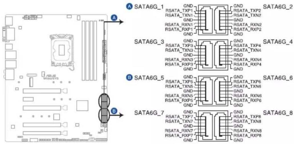
W680/SYS Intel® Serial ATA 6 Gb/s connectors

To create a RAID set with the connected storage devices, please refer to Chapter 5.
2. Front Panel Audio connector
This connector is for a chassis-mounted front panel audio I/O module that supports HD Audio. Connect one end of the front panel audio I/O module cable to this connector.
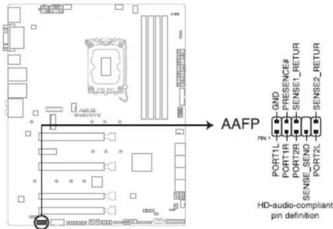
W680/SYS Front panel audio connector

We recommend that you connect a high-definition front panel audio module to this connector to avail of the motherboard's high-definition audio capability.
3. TPM connector
This connector supports a Trusted Platform Module (TPM) system, which securely stores keys, digital certificates, passwords, and data. A TPM system also helps enhance network security, protect digital identities, and ensures platform integrity.

W680/SYS SPI_TPM connector
The TPM module is purchased separately.
4. USB 3.2 Gen 2x2 Type-C® Front Panel connector
The USB 3.2 Gen 2x2 Type-C® connector allows you to connect a USB 3.2 Gen 2x2 Type-C® module for additional USB 3.2 Gen 2x2 ports on the front panel. The USB 3.2 Gen 2x2 Type-C® connector provides data transfer speeds of up to 20 Gb/s.

W680/SYS USB 3.2 Gen 2 connector

The USB 3.2 Gen 2x2 Type-C® module is purchased separately.
5. USB 3.2 Gen 1 connector
This connector allows you to connect a USB 3.2 Gen 1 module for additional USB 3.2 Gen 1 front or rear panel ports. With an installed USB 3.2 Gen 1 module, you can enjoy all the benefits of USB 3.2 Gen 1 including faster data transfer speeds of up to 5 Gb/s, faster charging time for USB-chargeable devices, optimized power efficiency, and backward compatibility with USB 2.0.

W680/SYS USB 3.2 Gen 1 connector

The USB 3.2 Gen 1 module is purchased separately.
The plugged USB 3.2 Gen 1 device may run on xHCI or EHCI mode depending on the operating system's setting.
6. USB 2.0 connectors
The 10-1 pin connector allows you to connect a USB 2.0 module for additional USB 2.0 front or rear panel ports. The 4-pin USB (Universal Serial Bus) Type-A port is available for connecting USB 2.0 devices. These USB connectors comply with USB 2.0 specification that supports up to 480 Mbps connection speed.


DO NOT connect a 1394 cable to the USB connectors. Doing so will damage the motherboard!
7. Serial Port connector
This connector is for a serial (COM) port. Connect the serial port module cable to this connector, then install the module to a slot opening at the back of the system chassis.

W680/SYS Serial port connector

The serial port module is purchased separately.
8. Fan connectors
Connect the fan cables to the fan connectors on the motherboard, ensuring that the black wire of each cable matches the ground pin of the connector.


- DO NOT forget to connect the fan cables to the fan connectors. Insufficient air flow inside the system may damage the motherboard components. These are not jumpers! Do not place jumper caps on the fan connectors!
- Ensure that the CPU fan cable is securely installed to the CPU fan connector.
9. Digital Audio connector
This connector is for an additional Sony/Philips Digital Interface (S/PDIF) port. Connect the S/PDIF Out module cable to this connector, then install the module to a slot opening at the back of the system chassis.

W680/SYS Digital audio connector

The S/PDIF module is purchased separately.
10. System panel connector
This connector supports several chassis-mounted functions.

• System power LED (2-pin or 3-1 pin PLED)
The 2-pin or 3-1 pin connector is for the system power LED. Connect the chassis power LED cable to this connector. The system power LED lights up when you turn on the system power, and blinks when the system is in sleep mode.
- Hard disk drive activity LED (2-pin HDD_LED)
This 2-pin connector is for the HDD Activity LED. Connect the HDD Activity LED cable to this connector. The HDD LED lights up or flashes when data is read from or written to the HDD.
• System warning speaker (4-pin SPEAKER)
This 4-pin connector is for the chassis-mounted system warning speaker. The speaker allows you to hear system beeps and warnings.
• ATX power button/soft-off button (2-pin PWRSW)
This connector is for the system power button. Pressing the power button turns the system on or puts the system in sleep or soft-off mode depending on the operating system settings. Pressing the power switch for more than four seconds while the system is ON turns the system OFF.
- Reset button (2-pin RESET)
This 2-pin connector is for the chassis-mounted reset button for system reboot without turning off the system power.
- Chassis intrusion connector (2-pin CHASSIS)
This connector is for a chassis-mounted intrusion detection sensor or switch. Connect one end of the chassis intrusion sensor or switch cable to this connector. The chassis intrusion sensor or switch sends a high-level signal to this connector when a chassis component is removed or replaced. The signal is then generated as a chassis intrusion event.
11. ATX power connectors
These connectors are for ATX power supply plugs. The power supply plugs are designed to fit these connectors in only one orientation. Find the proper orientation and push down firmly until the connectors completely fit.

W680/SYS ATX power connectors
- DO NOT forget to connect the 24-pin and the 8-pin power plugs, or 24-pin and 4-pin power plugs (for 300W PSUs); otherwise, the system will not boot up.
- For a fully configured system, we recommend that you use a power supply unit (PSU) that complies with ATX 12 V Specification 2.0 (or later version) and provides a minimum power of 350W.
- When using a 300W PSU that only has a 4-pin 12V power connector, the 8-pin Power Plug LED may light up when the 4-pin 12V connector is connected. This is normal and will not affect the motherboard powering up and other functions.
- Do not forget to connect the 8-pin EATX12V power plug. Otherwise, the system will not boot.
- We recommend that you use a PSU with a higher power output when configuring a system with more power-consuming devices. The system may become unstable or may not boot up if the power is inadequate.
- If you want to use two or more high-end PCI Express x16 cards, use a PSU with 1000W power or above to ensure system stability.
12. M.2 sockets
These sockets allow you to install M.2 SSD modules.


- M.2_1 socket supports PCIe 4.0 x4 M Key design and type 2242 / 2260 / 2280 PCIe storage devices.
- M.2_2 socket supports PCIe 3.0 x4 M Key design and type 2242 / 2260 / 2280 PCIe storage devices.
- M.2_3 socket supports PCIe 4.0 x4 M Key design and type 2242 / 2260 / 2280 / 22110 PCIe storage devices. • These sockets support IRST (Intel® Rapid Storage Technology).
- The M.2_1 socket does not support Intel® Optane memory.

The M.2 SSD module is purchased separately.
13. M.2 slot (Key E)
The M.2 Wi-Fi slot allows you to install an M.2 Wi-Fi module (E-key, type 2230).
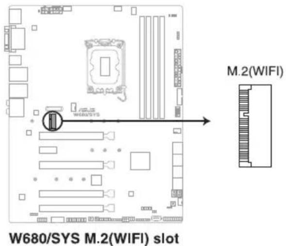

- The M.2 Wi-Fi module may come pre-installed on selected models. • The M.2 Wi-Fi module is purchased separately.
14. LPT connector
The LPT (Line Printing Terminal) connector supports devices such as a printer. LPT standardizes as IEEE 1284, which is the parallel port interface on IBM PC-compatible computers.

15. Thermal Sensor connector
The Thermal Sensor connector allows you to connect a sensor to monitor the temperature of the devices and the critical components inside the motherboard. Connect the thermal sensor and place it on the device or the motherboard's component to detect its temperature.


The thermal sensor is purchased separately.
16. Thunderbolt™ connector (14-1 pin TB_HEADER)
The Thunderbolt™ connector allows you to connect an add-on Thunderbolt™ I/O card that supports Intel®'s Thunderbolt™ Technology, allowing you to connect Thunderbolt™-enabled devices to form a daisy-chain configuration.


- The add-on Thunderbolt™ I/O card and Thunderbolt™ cables are purchased separately.
- Please visit the official website of your purchased Thunderbolt™ card for more details on compatibility.
BIOS Setup
4
This chapter tells how to change the system settings through the BIOS Setup menus. Detailed descriptions of the BIOS parameters are also provided.
4.1 Introduction to the BIOS
The new ASUS UEFI BIOS is a Unified Extensible Interface that complies with UEFI architecture, offering a user-friendly interface that goes beyond the traditional keyboard-only BIOS controls to enable a more flexible and convenient mouse input. You can easily navigate the new UEFI BIOS with the same smoothness as your operating system. The term "BIOS" in this user manual refers to "UEFI BIOS" unless otherwise specified.
BIOS (Basic Input and Output System) stores system hardware settings such as storage device configuration, overclocking settings, advanced power management, and boot device configuration that are needed for system startup in the motherboard CMOS. In normal circumstances, the default BIOS settings apply to most conditions to ensure optimal performance. DO NOT change the default BIOS settings except in the following circumstances:
- An error message appears on the screen during the system bootup and requests you to run the BIOS Setup.
- You have installed a new system component that requires further BIOS settings or update.
Inappropriate BIOS settings may result in instability or boot failure. We strongly recommend that you change the BIOS settings only with the help of trained service personnel.
- When downloading or updating the BIOS file for your motherboard, rename it as W680S.CAP. The name of the CAP file varies depending on models. Refer to the user manual that came with your motherboard for the name.
- The screenshots in this manual are for reference only; please refer to the latest BIOS version for settings and options.
- BIOS settings and options may vary due to different BIOS release versions. Please refer to the latest BIOS version for settings and options.
4.2 BIOS setup program
Use the BIOS Setup to update the BIOS or configure its parameters. The BIOS screen includes navigation keys and brief onscreen help to guide you in using the BIOS Setup program.
Entering BIOS at startup
To enter BIOS Setup at startup, press <Delete> or <F2> during the Power-On Self Test (POST). If you do not press <Delete> or <F2>, POST continues with its routines.
Entering BIOS Setup after POST
To enter BIOS Setup after POST:
- Press <Ctrl> + <Alt> + <Delete> simultaneously.
- Press the reset button on the system chassis.
Press the power button to turn the system off then back on. Do this option only if you failed to enter BIOS Setup using the first two options.
After doing either of the three options, press <Delete> key to enter BIOS.

- The BIOS setup screens shown in this section are for reference purposes only, and may not exactly match what you see on your screen.
- Ensure that a USB mouse is connected to your motherboard if you want to use the mouse to control the BIOS setup program.
- If the system becomes unstable after changing any BIOS setting, load the default settings to ensure system compatibility and stability. Select the Load Optimized Defaults item under the Exit menu or press the hotkey. See section Exit menu for details.
- If the system fails to boot after changing any BIOS setting, try to clear the CMOS and reset the motherboard to the default value. See your motherboard manual for information on how to erase the RTC RAM.
- The BIOS setup program does not support Bluetooth devices.
BIOS menu screen
The BIOS Setup program can be used under two modes: EZ Mode and Advanced Mode. You can change modes from Setup Mode in Boot menu or by pressing the hotkey.

The BIOS settings and options for each motherboard may differ slightly from the options in this manual. Please refer to the BIOS of your motherboard for the settings and options.
4.2.1 EZ Mode
The EZ Mode provides you an overview of the basic system information, and allows you to select the display language, system performance, mode, and boot device priority. To access the Advanced Mode, select Advanced Mode or press the hotkey for the advanced BIOS settings.

The default screen for entering the BIOS setup program can be changed. Refer to the Setup Mode item in section Boot menu for details.


The boot device options vary depending on the devices you installed to the system.
4.2.2 Advanced Mode
The Advanced Mode provides advanced options for experienced end-users to configure the BIOS settings. The figure below shows an example of the Advanced Mode. Refer to the following sections for the detailed configurations.

To switch from EZ Mode to Advanced Mode, click Advanced Mode (F7) or press the hotkey.

Menu bar
The menu bar on top of the screen has the following main items:
| My Favorites | For saving the frequently-used system settings and configuration. |
| Main | For changing the basic system configuration |
| Advanced For changing the advanced system settings | |
| Monitor | For displaying the system temperature, power status, and changing the fan settings. |
| Boot For changing the system boot configuration | |
| Tool For configuring options for special functions | |
| Exit | For selecting the exit options and loading default settings |
Menu items
The highlighted item on the menu bar displays the specific items for that menu. For example, selecting Main shows the Main menu items.
The other items (My Favorites, Advanced, Monitor, Boot, Tool, and Exit) on the menu bar have their respective menu items.
Submenu items
A greater than sign (>) before each item on any menu screen means that the item has a submenu. To display the submenu, select the item and press .
Language
This button above the menu bar contains the languages that you can select for your BIOS. Click this button to select the language that you want to display in your BIOS screen.
MyFavorite
This button above the menu bar shows all BIOS items in a Tree Map setup. Select frequently-used BIOS settings and save it to MyFavorites menu. You may also access this item by pressing the key on the keyboard.

Refer to section My Favorites for more information.
QFan Control
This button above the menu bar displays the current settings of your fans. Use this button to manually tweak the fans to your desired settings. You may also access this item by pressing the key on the keyboard.

Refer to section QFan Control for more information.
Search
This button allows you to search for BIOS items by entering its name. Enter the item name to find the related item listing. You may also access this item by pressing the key on the keyboard.
ReSize BAR
This button allows you to turn the ReSize BAR function on or off.
[On] Enable ReSize BAR support to fully harness GPU memory. CSM (Compatibility Support Module) will be disabled.
[Off] ReSize BAR support will be disabled.
MemTest86
This button above the menu bar allows you to activate MemTest86. MemTest86 can be used to scan and detect if there are problems with your memory. For more information on using MemTest86, please refer to www.asus.com/support.

- Please save all changes made before using MemTest86.
- There will be a few seconds of loading time after clicking the MemTest86 button.
Hot keys
This button contains the navigation keys for the BIOS setup program. Use the navigation keys to select items in the menu and change the settings.
Scroll bar
A scroll bar appears on the right side of a menu screen when there are items that do not fit on the screen. Press the Up/Down arrow keys or / keys to display the other items on the screen.
General help
At the bottom of the menu screen is a brief description of the selected item. Use the key to capture the BIOS screen and save it to the removable storage device.
Configuration fields
These fields show the values for the menu items. If an item is user-configurable, you can change the value of the field opposite the item. You cannot select an item that is not user-configurable.
A configurable field is highlighted when selected. To change the value of a field, select it and press to display a list of options.
Last Modified button
This button shows the items that you last modified and saved in BIOS Setup.
4.2.3 Q-Fan Control
The QFan Control allows you to set a fan profile or manually configure the operating speed of your CPU and chassis fans.
![Click to select a fan to be configured Click to activate PWM Mode Click to activate DC Mode Q-Fan Control Select your target fan and then move the slider to select any of these profiles (Standard, Silent, Turbo and Full Speed). You can also move the slider to [Manual] and manually configure the fan'…](/content/2026/05/981869/images/d523911f7ebcbc8f32a25a23dc9d98741ff061a31eb06f4959ddd72d76f9ab97.jpg)
Configuring fans manually
Select Manual from the list of profiles to manually configure your fans' operating speed.

To configure your fans:
- Select the fan that you want to configure and to view its current status.
- Click and drag the speed points to adjust the fans' operating speed.
- Click Apply to save the changes then click Exit (ESC).
4.3 My Favorites
My Favorites is your personal space where you can easily save and access your favorite BIOS items.

My Favorites comes with several performance, power saving, and fast boot related items by default. You can personalize this screen by adding or removing items.
Adding items to My Favorites
To add BIOS items:
- Press on your keyboard or click MyFavorite from the BIOS screen to open Setup Tree Map screen.
- On the Setup Tree Map screen, select the BIOS items that you want to save in My Favorites screen.
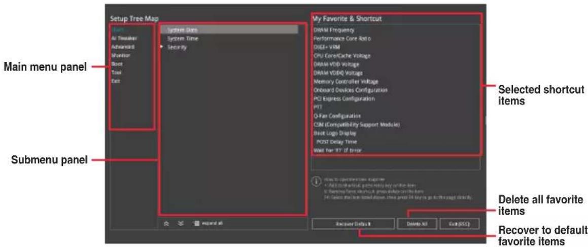
- Select an item from main menu panel, then click the submenu that you want to save as favorite from the submenu panel and click +press on your keyboard.

You cannot add the following items to My Favorite items:
- Items with submenu options
- User-managed items such as language and boot order
- Configuration items such as Memory SPD Information, system time and date.
- Click Exit (ESC) or press key to close Setup Tree Map screen.
- Go to My Favorites menu to view the saved BIOS items.
4.4 Main menu
The Main menu screen appears when you enter the Advanced Mode of the BIOS Setup program. The Main menu provides you an overview of the basic system information, and allows you to set the system date, time, language, and security settings.

Security
The Security menu items allow you to change the system security settings.


- If you have forgotten your BIOS password, erase the CMOS Real Time Clock (RTC) RAM to clear the BIOS password. See the motherboard for information on how to erase the RTC RAM via the Clear CMOS jumper.
- The Administrator or User Password items on top of the screen show the default [Not Installed]. After you set a password, these items show [Installed].
Administrator Password
If you have set an administrator password, we recommend that you enter the administrator password for accessing the system. Otherwise, you might be able to see or change only selected fields in the BIOS setup program.
To set an administrator password:
- Select the Administrator Password item and press .
- From the Create New Password box, key in a password, then press .
- Re-type to confirm the password then select OK.
To change an administrator password:
- Select the Administrator Password item and press .
- From the Enter Current Password box, key in the current password, then press .
- From the Create New Password box, key in a new password, then press .
- Re-type to confirm the password then select OK.
To clear the administrator password, follow the same steps as in changing an administrator password, but leave other fields blank then select OK to continue. After you clear the password, the Administrator Password item on top of the screen shows [Not Installed].
User Password
If you have set a user password, you must enter the user password for accessing the system. The User Password item on top of the screen shows the default [Not Installed]. After you set a password, this item shows [Installed].
To set a user password:
- Select the User Password item and press .
- From the Create New Password box, key in a password, then press .
- Re-type to confirm the password then select OK.
To change a user password:
- Select the User Password item and press .
- From the Enter Current Password box, key in the current password, then press .
- From the Create New Password box, key in a new password, then press .
- Re-type to confirm the password then select OK.
To clear the user password, follow the same steps as in changing a user password, but leave other fields blank then select OK to continue. After you clear the password, the User Password item on top of the screen shows [Not Installed].
4.5 Advanced menu
The Advanced menu items allow you to change the settings for the CPU and other system devices.

Be cautious when changing the settings of the Advanced menu items. Incorrect field values can cause the system to malfunction.

4.5.1 Platform Misc Configuration
The items in this menu allow you to configure the platform-related features.

PCI Express Native Power Management
Allows you to enhance the power saving feature of PCI Express and perform Active State Power Management (ASPM) operations in the operating system when set to [Enabled]. Configuration options: [Disabled] [Enabled]

The following item appears only when PCI Express Native Power Management is set to [Enabled].
Native ASPM
Set this item to [Enabled] for OS Controlled ASPM, or set this item to [Disabled] for BIOS controlled ASPM.
Configuration options: [Auto] [Enabled] [Disabled]
PCH - PCI Express
DMI Link ASPM Control
Allows you to control the Active State Power Management of the DMI Link.
Configuration options: [Disabled] [L1] [Auto]
ASPM
Allows you to select the ASPM state for energy-saving conditions.
Configuration options: [Disabled] [L1] [Auto]
L1 Substates
Allows you to select the PCI Express L1 Substates settings.
Configuration options: [Disabled] [L1.1] [L1.1 & L1.2]
SA - PCI Express
DMI ASPM Control
Allows you to set the DMI ASPM Support.
Configuration options: [Disabled] [Auto] [ASPM L1]
DMI Gen3 ASPM
Allows you to set the DMI Gen3 ASPM Support.
Configuration options: [Disabled] [Auto] [ASPM L1]
PEG - ASPM
Allows you to control the ASPM support for the PEG 0. This has no effect if PEG is not the currently active device.
Configuration options: [Disabled] [L0s] [L1] [L0sL1]
PCI Express Clock Gating
Allows you to enable or disable PCI Express Clock Gating for each root port.
Configuration options: [Disabled] [Enabled]
4.5.2 CPU Configuration
The items in this menu show the CPU-related information that the BIOS automatically detects. Scroll down to display other BIOS items.

The items in this menu may vary based on the CPU installed.

Efficient Core Information
This submenu displays the Efficient Core Information.
Performance Core Information
This submenu displays the Performance Core Information.
Hardware Prefetcher
Allows you to enable or disable the MLC streamer prefetcher.
Configuration options: [Disabled] [Enabled]
Adjacent Cache Line Prefetch
Allows you to prefetch adjacent cache lines, reducing the DRAM loading time and improving the system performance.
Configuration options: [Disabled] [Enabled]
Intel (VMX) Virtualization Technology
When set to [Enabled], VMM can utilize the additional hardware capabilities provided by Vanderpool Technology.
Configuration options: [Disabled] [Enabled]

The following items appear only when Intel Trusted Execution Technology is set to [Disabled].
Active Performance Cores
Allows you to select the number of CPU cores to activate in each processor package.
Configuration options: [All] [1] - [7]
Active Efficient Cores
Allows you to select the number of Efficient cores to activate in each processor package.
Configuration options: [All] [0] - [7]

Number of Cores and Efficient Cores are looked at together. When both are set to 0, Pcode will enable all cores.
Hyper-Threading
Allows a hyper-threading processor to appear as two logical processors, allowing the operating system to schedule two threads or processes simultaneously.
[Enabled] For two threads per activated core.
[Disabled] For only one thread per activated core.

The following item appears only when Intel (VMX) Virtualization Technology is set to [Enabled].
Intel Trusted Execution Technology
Allows you to enable utilization of additional hardware capabilities provided by Intel(R)
Trusted Execution Technology.
Configuration options: [Disabled] [Enabled]

Changes require a full power cycle to take effect.

The following items appear only when Intel Trusted Execution Technology is set to [Enabled].
Alias Check Request
Enables Txt Alias Checking capability.
Configuration options: [Disabled] [Enabled]

- Changes require full Txt capability before it will take effect.
- This is a one time only change, and will be reset on the next reboot.
DPR Memory Size (MB)
Reserve DPR memory size (0-255) MB.
Configuration options: [0] - [255]
Reset AUX Content
Reset TPM Aux Content. Txt may not be functional after AUX content gets reset.
Total Memory Encryption
Allows you to configure the Total Memory Encryption (TME) to protect DRAM data from physical attacks.
Configuration options: [Disabled] [Enabled]
Legacy Game Compatibility Mode
When set to [Enabled], pressing the scroll lock key will toggle the Efficient-cores between being parked when Scroll Lock LED is on and un-parked when LED is off.
Configuration options: [Disabled] [Enabled]
CPU - Power Management Control
The items in this submenu allow you to manage and configure the CPU's power.
Boot performance mode
Allows you to select the performance state that the BIOS will set starting from the reset vector.
Configuration options: [Max Battery] [Max Non-Turbo Performance]
[Turbo Performance] [Auto]
Intel(R) SpeedStep(tm)
Allows more than two frequencies to be supported.
Configuration options: [Disabled] [Enabled]
Intel(R) Speed Shift Technology
Allows you to disable or enable Intel(R) Speed Shift Technology support. When enabled, CPPC v2 interface allows hardware controlled P-states.
Configuration options: [Disabled] [Enabled]
Intel(R) Turbo Boost Max Technology 3.0
Allows you to disable or enable Intel(R) Turbo Boost Max Technology 3.0 support.
Disabling will report the maximum ratio of the slowest core in _CPC object.
Configuration options: [Disabled] [Enabled]
Turbo Mode
Allows you to automatically set the CPU cores to run faster than the base operating frequency when it is below the operating power, current, and temperature specification limit.
Configuration options: [Disabled] [Enabled]
Acoustic Noise Settings
The items in this submenu allow you to configure Acoustic Noise Settings for IA, GT, and SA domains.
Acoustic Noise Settings
Acoustic Noise Mitigation
Enabling this option will help mitigate acoustic noise on certain SKUs when the CPU is in deeper C state.
Configuration options: [Disabled] [Enabled]

The following items appear only when Acoustic Noise Mitigation is set to [Enabled].
Pre Wake Time
Allows you to set the maximum Pre Wake randomization time in micro ticks. This is for acoustic noise mitigation Dynamic Periodicity Alteration (DPA) tuning. Use the <+> or <-> to adjust the value.
Configuration options: [0] - [255]
Ramp Up Time
Allows you to set the maximum Ramp Up randomization time in micro ticks. This is for acoustic noise mitigation Dynamic Periodicity Alteration (DPA) tuning. Use the <+> or <-> to adjust the value.
Configuration options: [0] - [255]
Ramp Down Time
Allows you to set the maximum Ramp Down randomization time in micro ticks. This is for acoustic noise mitigation Dynamic Periodicity Alteration (DPA) tuning. Use the <+> or <-> to adjust the value.
Configuration options: [0] - [255]
IA VR Domain
Disable Fast PKG C State Ramp for IA Domain
This option needs to be configured to reduce acoustic noise during deeper C states.
[FALSE] Don't disable Fast ramp during deeper C states.
[TRUE] Disable Fast ramp during deeper C state.
Slow Slew Rate for IA Domain
Set VR IA Slow Slew Rate for Deep Package C State ramp time; Slow slew rate equals to Fast divided by number, the number is 2, 4, 8 to slow down the slew rate to help minimize acoustic noise.
Configuration options: [Fast/2] [Fast/4] [Fast/8]
GT VR Domain
Disable Fast PKG C State Ramp for GT Domain
This option needs to be configured to reduce acoustic noise during deeper C states.
[FALSE] Don't disable Fast ramp during deeper C states.
[TRUE] Disable Fast ramp during deeper C state.
Slow Slew Rate for GT Domain
Set VR GT Slow Slew Rate for Deep Package C State ramp time; Slow slew rate equals to Fast divided by number, the number is 2, 4, 8 to slow down the slew rate to help minimize acoustic noise.
Configuration options: [Fast/2] [Fast/4] [Fast/8]
CPU C-states
Allows you to enable or disable CPU Power Management. Allows CPU to go to C states when it's not 100% utilized.
Configuration options: [Auto] [Disabled] [Enabled]

The following items appear only when CPU C-states is set to [Enabled].
Enhanced C-States
Allows you to enable or disable C1E. When enabled, CPU will switch to minimum speed when all cores enter C-State.
Configuration options: [Enabled] [Disabled]
Package C State Limit
Allows you to set the C-state limit for the CPU package. Setting to [CPU Default] will leave it as the Factory default value. Setting to [Auto] will initialize the deepest available Package C State Limit.
Configuration options: [C0/C1] [C2] [C3] [C6] [C7] [C7s] [C8] [C9] [C10] [CPU Default] [Auto]
Thermal Monitor
Allows you to enable or disable the Thermal Monitor.
Configuration options: [Disabled] [Enabled]
Dual Tau Boost
Allows you to enable Dual Tau Boost feature. This is only applicable for Desktop 35W/65W/125W sku. When DPTF is enabled this feature is ignored.
Configuration options: [Disabled] [Enabled]
4.5.3 System Agent (SA) Configuration
The items in this menu allow you to change the System Agent (SA) parameters.

VT-d
Allows you to enable virtualization technology function on memory control hub.
Configuration options: [Enabled] [Disabled]

The following item appears only when VT-d is set to [Enabled].
Control Iommu Pre-boot Behavior
Allows you to enable IOMMU in Pre-boot environment (if DMAR table is installed in DXE and if VTD_INFO_PPI is installed in PEI).
Configuration options: [Disable IOMMU] [Enable IOMMU during boot]
Memory Configuration
The items in this submenu allow you to set memory configuration parameters.
Memory Remap
Allows you to enable or disable memory remap above 4GB.
Configuration options: [Enabled] [Disabled]
Graphics Configuration
The items in this submenu allow you to select a primary display from CPU Graphics, PEG Graphics devices, or PCIe Graphics devices.
Primary Display
Allows you to select the primary display from CPU Graphics / PEG Graphics / PCIe Graphics device.
Configuration options: [Auto] [CPU Graphics] [PEG Slot] [PCIE]
iGPU Multi-Monitor
Set this item to [Enabled] to empower both integrated and discrete graphics for multi-monitor output. iGPU shared system memory size will be fixed at 64M.
Configuration options: [Disabled] [Enabled]
DVMT Pre-Allocated
Allows you to select the DVMT 5.0 Pre-Allocated (Fixed) Graphics Memory size used by the Internal Graphics Device.
Configuration options: [32M] [64M] [96M] [128M] [160M] [192M] [224M] [256M] [288M] [320M] [352M] [384M] [416M] [448M] [480M] [512M]
RC6(Render Standby)
Allows you to enable render standby support.
Configuration options: [Disabled] [Enabled]
VMD setup menu
The items in this submenu allow you to set the VMD configuration settings.
Enable VMD controller
Allows you to enable or disable the VMD controller.
Configuration options: [Disabled] [Enabled]

Setting Enable VMD controller to [Disabled] may result in data loss.

The following items appear only when Enable VMD controller is set to [Enabled].
Map PCIE Storage under VMD
Allows you to map or unmap PCIE Storage to VMD.
Configuration options: [Disabled] [Enabled]

Ensure to set Map SATA Controller under VMD to [Disabled] if you set Map PCIE Storage under VMD to [Enabled].
Map SATA Controller under VMD
Allows you to map or unmap this Root Port to VMD.
Configuration options: [Disabled] [Enabled]

Ensure to set Map PCIE Storage under VMD to [Disabled] if you set Map SATA Controller under VMD to [Enabled].
PCI Express Configuration
The items in this submenu allow you to configure the PCIe Speeds for the different onboard slots.
M.2_1 Link Speed
Allows you to configure the PCIe speed for M.2_1 slot.
Configuration options: [Auto] [Gen1] [Gen2] [Gen3] [Gen4]
PCIEX16(G5) Link Speed
Allows you to configure the PCIe speed for PCIEX16(G5) slot.
Configuration options: [Auto] [Gen1] [Gen2] [Gen3] [Gen4] [Gen5]
PCIEX16_2 Link Speed
Allows you to configure the PCIe speed for PCIEX16_2 slot.
Configuration options: [Auto] [Gen1] [Gen2] [Gen3] [Gen4] [Gen5]
4.5.4 PCH Configuration
The items in this menu allow you to change the PCIe configurations for slots supported by the PCH.

PCI Express Configuration
The items in this submenu allow you to configure the PCIe Speeds for the different onboard slots supported by the PCH.
PCIEX16(G3)_2 Link Speed
Allows you to configure the PCIe speed for PCIEX16(G3)_2 slot.
Configuration options: [Auto] [Gen1] [Gen2] [Gen3]
M.2_2 Link Speed
Allows you to configure the PCIe speed for M.2_2 slot.
Configuration options: [Auto] [Gen1] [Gen2] [Gen3]
PCIEX16(G4)_4 Link Speed
Allows you to configure the PCIe speed for PCIEX16(G4)_4 slot.
Configuration options: [Auto] [Gen1] [Gen2] [Gen3]
PCIEX16(G4)_3 Link Speed
Allows you to configure the PCIe speed for PCIEX16(G4)_3 slot.
Configuration options: [Auto] [Gen1] [Gen2] [Gen3] [Gen4]
M.2_3 Link Speed
Allows you to configure the PCIe speed for M.2_2 slot.
Configuration options: [Auto] [Gen1] [Gen2] [Gen3] [Gen4]
4.5.5 PCH Storage Configuration
While entering Setup, the BIOS automatically detects the presence of SATA devices. The SATA Port items show Empty if no SATA device is installed to the corresponding SATA port.
Scroll down to display the other BIOS items.

SATA Controller(s)
Allows you to enable or disable the SATA Device.
Configuration options: [Disabled] [Enabled]
Aggressive LPM support
Allows PCH to aggressively enter link power state.
Configuration options: [Disabled] [Enabled]
SMART Self Test
S.M.A.R.T. (Self-Monitoring, Analysis and Reporting Technology) is a monitoring system that shows a warning message during POST (Power-on Self Test) when an error occurs in the hard disks.
Configuration options: [Disabled] [Enabled]
SATA6G_1 - SATA6G_8
Allows you to enable or disable the selected SATA port.
Configuration options: [Disabled] [Enabled]
SATA6G_1 - SATA6G_8 Hot Plug
Designates this port as Hot Pluggable.
Configuration options: [Disabled] [Enabled]
4.5.6 PCH-FW Configuration
The items in this menu allow you to configure the firmware TPM.

PTT
Allows you to enable or disable PTT in SkuMgr.
Configuration options: [Disable] [Enable]
Extend CSME Measurement to TPM-PCR
Allows you to enable or disable Extend CSME Measurements to TPM-PCR[0] and AMR Config to TPM-PCR[1].
Configuration options: [Disabled] [Enabled]
4.5.7 AMT Configuration
The items in this menu allow you to configure Intel(R) Active Management Technology parameters.

USB Provisioning of AMT
Allows you to enable or disable AMT USB provisioning. Configuration options: [Disabled] [Enabled]
MAC Pass Through
Allows you to enable or disable MAC Pass Through function. Configuration options: [Disabled] [Enabled]
Activate Remote Assistance Process
Allows you to trigger CIRA boot. Configuration options: [Disabled] [Enabled]

Network Access must be activated first from MEBx Setup.
Unconfigure ME
Unconfigure ME with resetting MEBx password to default on next boot. Configuration options: [Disabled] [Enabled]
ASF Configuration
The items in this submenu allow you to configure Alert Standard Format parameters.
PET Progress
Allows you to enable or disable PET Events Progress to receive PET Events. Configuration options: [Disabled] [Enabled]
WatchDog
Allows you to enable or disable WatchDog Timer. Configuration options: [Disabled] [Enabled]
OS Timer
Allows you to set OS watchdog timer.
Configuration options: [0] - [65535]
BIOS Timer
Allows you to set the BIOS watchdog timer.
Configuration options: [0] - [65535]
ASF Sensors Table
Adds the ASF Sensor Table into the ASF! ACPI Table.
Configuration options: [Disabled] [Enabled]
Secure Erase Configuration
The items in this submenu allow you to configure secure erase.
Secure Erase mode
Change the Secure Erase module behavior.
[Simulated] Performs SE flow without erasing SSD.
[Real] Erase SSD.
Force Secure Erase
Allows you to force Secure Erase on next boot.
Configuration options: [Disabled] [Enabled]
One Click Recovery (OCR) Configuration
The items in this submenu allow you to configure settings for One Click Recovery. This will allow access for AMT to boot a recovery OS application.
OCR Https Boot
Allows you to enable or disable One Click Recovery Https Boot.
Configuration options: [Disabled] [Enabled]
OCR PBA Boot
Allows you to enable or disable One Click Recovery PBA Boot.
Configuration options: [Disabled] [Enabled]
OCR Windows Recovery Boot
Allows you to enable or disable One Click Recovery Windows Recovery Boot.
Configuration options: [Disabled] [Enabled]
OCR Disable Secure Boot
Allows CSME to request Secure Boot to be disabled for One Click Recovery.
Configuration options: [Disabled] [Enabled]
4.5.8 Thunderbolt(TM) Configuration
The items in this menu allow you to configure Thunderbolt settings.

PCIE Tunneling over USB4
Allows you to enable or disable PCIE Tunneling over USB4. Configuration options: [Disabled] [Enabled]
Discrete Thunderbolt(TM) Support
Allows you to enable or disable Discrete Thunderbolt(TM) Support. Configuration options: [Disabled] [Enabled]

- Please set Control Iommu Pre-boot Behavior in the System Agent(SA) Configuration page to [Enabled] to support DMA Protection Feature.
- The following items appear only when [Enabled]. Discrete Thunderbolt(TM) Support is set to
Wake From Thunderbolt(TM) Devices
Allows you to enable or disable system wake from Thunderbolt(TM) devices. Configuration options: [Disabled] [Enabled]
Discrete Thunderbolt(TM) Configuration
The items in this submenu allow you to configure Discrete Thunderbolt(TM) related configurations.
DTBT Go2Sx Command
Allows you to enable the command to put DTBT into Sx state while system is going into Sx. Configuration options: [Disabled] [Enabled]
Windows 10 Thunderbolt Support
Allows you to specify Windows 10 Thunderbolt support level. [Enable + RTD3] OS Native support plus RTD3. [Disabled] No OS native support.
DTBT Controller 0 Configuration
DTBT Controller 0
Configuration options: [Disabled] [Enabled]
TBT Host Router
Allows you to enable host router based on ports available. Configuration options: [One Port] [Two Port]
Extra Bus Reserved
Allows you to select the TBT Root Port Type.
[56] One port Host.
[106] Two port Host.
Reserved Memory
Allows you to set the Reserved Memory for this Root Bridge. Use the <+> and <-> keys to adjust the value.
Configuration options: [1] - [4096]
Memory alignment
Allows you to set the memory alignment bits. Use the <+> and <-> keys to adjust the value.
Configuration options: [0] - [31]
Reserved PMemory
Allows you to set the Reserved Prefetchable Memory for this Root Bridge.
Use the <+> and <-> keys to adjust the value.
Configuration options: [1] - [4096]
PMemory alignment
Allows you to set the PMemory alignment bits. Use the <+> and <-> keys to adjust the value.
Configuration options: [0] - [31]
Reserved I/O
Use the <+> and <-> keys to adjust the value. The values range from 0 to 60 with an interval of 4.
Configuration options: [0] - [60]
4.5.9 Serial Port Console Redirection
The items in this menu allow you to configure serial port console redirection settings.
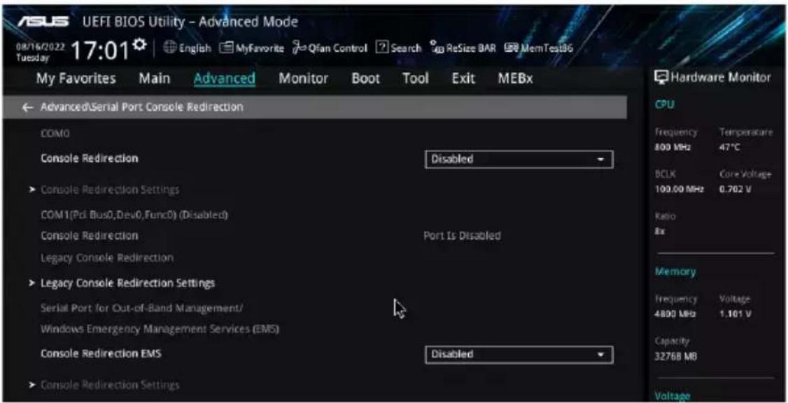
COM0 / COM1
Console Redirection
Allows you to enable or disable the console redirection feature.
Configuration options: [Disabled] [Enabled]

The following item appears only when Console Redirection for COM0 or COM1 is set to [Enabled].
Console Redirection Settings
These items become configurable only when you enable the Console Redirection item. The settings specify how the host computer and the remote computer (which the user is using) will exchange data. Both computers should have the same or compatible settings.
Terminal Type
Allows you to set the terminal type.
[VT100] ASCII char set.
[VT100+] Extends VT100 to support color, function keys, etc.
[VT-UTF8] Uses UTF8 encoding to map Unicode chars onto 1 or more bytes.
[ANSI] Extended ASCII char set.
Bits per second
Selects serial port transmission speed. The speed must be matched on the other side.
Long or noisy lines may require lower speeds.
Configuration options: [9600] [19200] [38400] [57600] [115200]
Data Bits
Configuration options: [7] [8]
Parity
A parity bit can be sent with the data bits to detect some transmission errors. [Mark] and [Space] parity do not allow for error detection. They can be used as an additional data bit.
[None] None
[Even] Parity bit is 0 if the number of 1's in the data bits is even.
[Odd] Parity bit is 0 if the number of 1's in the data bits is odd.
[Mark] Parity bit is always 1.
[Space] Parity bit is always 0.
Stop Bits
Stop bits indicate the end of a serial data packet. (A start bit indicates the beginning.) The standard setting is 1 stop bit. Communication with slow devices may require more than 1 stop bit.
Configuration options: [1] [2]
Flow Control
Flow control can prevent data loss from buffer overflow. When sending data, if the receiving buffers are full, a “stop” signal can be sent to stop the data flow. Once the buffers are empty, a “start” signal can be sent to re-start the flow. Hardware flow control uses two wires to send start/stop signals.
Configuration options: [None] [Hardware RTS/CTS]
VT -UTF8 Combo Key Support
This allows you to enable the VT-UTF8 Combination Key Support for ANSI/VT100 terminals.
Configuration options: [Disabled] [Enabled]
Recorder Mode
With this mode enabled only text will be sent. This is to capture Terminal data.
Configuration options: [Disabled] [Enabled]
Resolution 100x31
This allows you to enable or disable extended terminal solution.
Configuration options: [Disabled] [Enabled]
Putty Keypad
This allows you to select the FunctionKey and Keypad on Putty.
Configuration options: [VT100] [LINUX] [XTERMR6] [SCO] [ESCN] [VT400]
Legacy Console Redirection Settings
Redirection COM Port
Allows you to select a COM port to display redirection of Legacy OS and Legacy OPROM Messages.
Configuration options: [COM0] [COM1]
Resolution
This allows you to set the number of rows and columns supported on the Legacy OS.
Configuration options: [80x24] [80x25]
Redirection After POST
The default setting for this option is set to [Always Enable].
[Always Enable] Legacy Console Redirection is enabled for legacy OS.
[Bootloader] The legacy Console Redirection is disabled before booting to legacy OS.
Serial Port for Out-of-Band Management/
Windows Emergency Management Services (EMS)
Console Redirection EMS
Allows you to enable or disable the console redirection feature.
Configuration options: [Disabled] [Enabled]

The following item appears only when Console Redirection EMS is set to [Enabled].
Console Redirection Settings
Out-of-Band Mgmt Port
Microsoft Windows Emergency Management Services (EMS) allow for remote management of a Windows Server OS through a serial port.
Configuration options: [COM0] [COM1]
Terminal Type EMS
VT-UTF8 is the preferred terminal type for out-of-band management. The next best choice is VT100+, and then VT100. See above, in Console Redirection Settings page for more help with Terminal Type/Emulation.
Configuration options: [VT100] [VT100+] [VT-UTF8] [ANSI]
Bits per second EMS
Selects serial port transmission speed. The speed must be matched on the other side. Long or noisy lines may require lower speeds.
Configuration options: [9600] [19200] [57600] [115200]
Flow Control EMS
Flow control can prevent data loss from buffer overflow. When sending data, if the receiving buffers are full, a "stop" signal can be sent to stop the data flow. Once the buffers are empty, a "start" signal can be sent to re-start the flow. Hardware flow control uses two wires to send start/stop signals.
Configuration options: [None] [Hardware RTS/CTS] [Software Xon/Xoff]
4.5.10 Intel TXT Information
You may view the Intel TXT information in this menu.

4.5.11 PCI Subsystem Settings
The items in this menu allows you to configure PCI, PCI-X, and PCI Express Settings.

Above 4G Decoding
Allows you to enable or disable 64-bit capable devices to be decoded in above 4G address space. It only works if the system supports 64-bit PCI decoding.
Configuration options: [Disabled] [Enabled]

Only enabled under 64-bit operating system.
Re-Size BAR Support
If system has Resizable BAR capable PCIe Devices, this option enables or disables Resizable BAR Support. Configuration options: [Disabled] [Enabled]
SR-IOV Support
Allows you to enable or disable Single Root IO Virtualization Support if the system has SR-IOV capable PCIe devices. Configuration options: [Disabled] [Enabled]
4.5.12 USB Configuration
The items in this menu allow you to change the USB-related features.


The Mass Storage Devices item shows the auto-detected values. If no USB device is detected, the item shows None.
Legacy USB Support
[Enabled] Enabled the Legacy USB support. [Disabled] USB devices are available only for EFI applications.
[Auto] Automatically disabled the Legacy USB support if no USB devices are connected.
XHCI Hand-off
This is a workaround for OSes without XHCI hand-off support. The XHCI ownership change should be claimed by the XHCI driver. [Disabled] Support XHCI by XHCI drivers for operating systems with XHCI support. [Enabled] Support XHCI by BIOS for operating systems without XHCI support.
USB Single Port Control
Allows you to enable or disable the individual USB ports.

Refer to section Rear panel features in your motherboard's user manual for the location of the USB ports.
4.5.13 Network Stack Configuration
The items in this menu allow you to change the Network Stack Configuration.
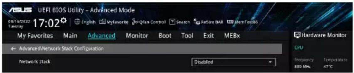
Network stack
Allows you to disable or enable the UEFI network stack.
Configuration options: [Disable] [Enable]

The following items appear only when Network Stack is set to [Enabled].
Ipv4/Ipv6 PXE Support
Allows you to enable or disable the IPv4/IPv6 PXE wake event.
Configuration options: [Disabled] [Enabled]
4.5.14 NVMe Configuration
This menu displays the NVMe controller and Drive information of the connected devices. You may press on a connected NVMe device which appears in this menu to view more information on the NVMe device.

4.5.15 HDD/SSD SMART Information
The items in this menu allow you to view the SMART information for connected storage devices.


NVM Express devices do not support SMART information.
4.5.16 APM Configuration
The items in this menu allow you to change the advanced power management settings.

Restore AC Power Loss
Allows your system to go to ON state, OFF state, or both states after an AC power loss.
When setting your system to [Last State], it goes to the previous state before the AC power loss.
Configuration options: [Power Off] [Power On] [Last State]
Max Power Saving
Configuration options: [Disabled] [Enabled]
ErP Ready
Allows you to switch off some power at S4+S5 or S5 to get the system ready for ErP requirement. When set to [Enabled], all other PME options are switched off. RGB LEDs and RGB/Addressable RGB Headers will also be disabled.
Configuration options: [Disabled] [Enabled (S4+S5)] [Enabled (S5)]
Power On By PCI-E
Allows you to enable or disable the Wake-on-LAN function of the onboard LAN controller or other installed PCI-E LAN cards.
Configuration options: [Disabled] [Enabled]
Power On By RTC
Allows you to enable or disable the RTC (Real-Time Clock) to generate a wake event and configure the RTC alarm date. When enabled, you can set the days, hours, minutes, or seconds to schedule an RTC alarm date.
Configuration options: [Disabled] [Enabled]
4.5.17 Onboard Devices Configuration
The items in this menu allow you to change the onboard devices settings. Scroll down to view the other BIOS items.
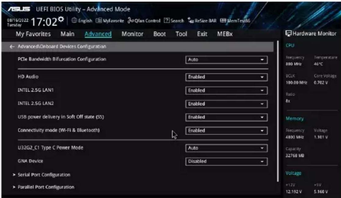
PCIe Bandwidth Bifurcation Configuration
[Auto] Run full PCIe X16 mode.
[X8/X8] Split up PCIEX16_1 that runs at X16 into X8/X8.
HD Audio
Controls the detection of the HD-Audio device.
[Disabled] HDA will be unconditionally disabled.
[Enabled] HDA will be unconditionally enabled.
Intel 2.5G LAN1/2
Allows you to enable or disable Intel LAN.
Configuration options: [Disabled] [Enabled]
USB power delivery in Soft Off state (S5)
Allows you to enable or disable USB power when your PC is in the S5 state.
Configuration options: [Disabled] [Enabled]
Onboard LED
Allows you to turn on or off the HDD and PLED LEDs.
Configuration options: [Disabled] [Enabled]
USB1 Type C Power Mode
[Auto] Power will be provided to USB 3.2 Gen 2 Type-C ports automatically when a device is detected.
[Enabled] Power will always be on for USB 3.2 Gen 2 Type-C ports.

Improper connection may damage the system permanently.
GNA Device
Allows you to enable or disable SA GNA Device.
Configuration options: [Enabled] [Disabled]
Serial Port Configuration
This submenu allows you to set parameters for the Serial Port.

This item will only function if there is a serial port (COM) connector on your motherboard.
Serial Port
Allows you to enable or disable the Serial port.
Configuration options: [Enabled] [Disabled]

The following item appears only when Serial Port is set to [Enabled].
Change settings
Allows you to select an optimal setting for the super IO device.
Configuration options: [IO=3F8h; IRQ=4] [IO=2F8h; IRQ=3] [IO=3E8h; IRQ=4]
[IO=2E8h; IRQ=3]
Parallel Port Configuration
This submenu allows you to set parameters for the Parallel Port (LPT/LPTE).
Parallel Port
Allows you to enable or disable the Parallel Port (LPT/LPTE).
Configuration options: [Disabled] [Enabled]
Change settings
Allows you to select an optimal setting for the super I/O device.
Configuration options: [IO=378h; IRQ=5] [IO=378h; IRQ=5,6,7,9,10,11,12] [IO=278h;
IRQ=5,6,7,9,10,11,12]
Device Mode
Allows you to change the Printer Port mode.
Configuration options: [STD Printer Mode] [SPP Mode] [EPP-1.9 and SPP Mode]
[EPP-1.7 and SPP Mode] [ECP Mode] [ECP and EPP-1.9 Mode]
[ECP and EPP-1.7 Mode]
4.5.18 Intel(R) Rapid Storage Technology
The items in this menu allow you to manage RAID volumes on the Intel(R) RAID Controller.

- The settings and options in this menu may vary depending on the storage devices connected. Please refer to the BIOS of your motherboard for the actual settings and options.
- Ensure to set the VMD configuration settings before using Intel(R) Rapid Storage Technology to create a RAID set.

4.6 Monitor menu
The Monitor menu displays the system temperature/power status, and allows you to change the fan settings. Scroll down to display the other BIOS items.

The settings and options of this menu may vary depending on your motherboard. Please refer to the BIOS of your motherboard for the actual settings and options.

Temperature Monitor
CPU Temperature, CPU Package Temperature, MotherBoard Temperature, VRM Thermistor Temperature, Chipset Temperature, T_Sensor Temperature, DIMM A1-2 Temperature, DIMM B1-2 Temperature [xxx°C/xxx°F]
The onboard hardware monitor automatically detects and displays the temperatures for the different components. Select [Ignore] if you do not wish to display the detected temperatures.
Fan Speed Monitor
CPU Fan Speed, CPU Optional Fan Speed, Chassis Fan 1-3 Speed, AIO PUMP Speed [xxxx RPM]
The onboard hardware monitor automatically detects and displays the fan speeds in rotations per minute (RPM). If the fan is not connected to the motherboard, the field shows N/A. Select [Ignore] if you do not wish to display the detected speed.
Voltage and Current Monitor
CPU Core Voltage, 12V Voltage, 5V Voltage, 3.3V Voltage, Memory Controller Voltage [x.xxx V]
The onboard hardware monitor automatically detects the voltage output through the onboard voltage regulators. Select [Ignore] if you do not want to detect this item.
CPU Core Current [xx A]
The onboard hardware monitor automatically detects the current output. Select [Ignore] if you do not want to detect this item.
Q-Fan Configuration
AI Cooling
ASUS AI Cooling will automatically manage and control all motherboard fans, ensuring the most efficient settings are set depending on the current system load and temperature. When you enable this function, AI Cooling function will try to lower fan speed to decrease fan noise without compromising current performance. You can keep track of fan performance via the ASUS Fan Xpert software with a blue dot in the Fan curve chart.
Configuration options: [Enabled] [Disabled]
Q-Fan Tuning
Click this item to automatically detect the lowest speed and configure the minimum duty cycle for each fan.

The process may take 2 to 5 minutes. DO NOT shut down or reset your system during the tuning process.
CPU Q-Fan Control
Allows you to set the CPU Q-Fan operating mode.
[Auto Detect] Detects the type of installed fan/pump and automatically switches the control modes.
[DC Mode] Enables the Q-Fan Control feature in DC mode for 3-pin fan/pump.
[PWM Mode] Enables the Q-Fan Control feature in PWM mode for 4-pin fan/pump.
CPU Fan Profile
Allows you to set the appropriate performance level of the assigned fan/pump. When selecting [Manual], we suggest raising your fan/pump duty to 100% if your CPU temperature exceeds 75°C. Please be noted CPU performance will throttle due to overheating with inefficient fan/pump duty.
Configuration options: [Standard] [Silent] [Turbo] [Full Speed] [Manual]

The following items appear only when CPU Fan Profile is set to [Standard], [Silent], [Turbo], or [Manual].
CPU Fan Step Up
Step up allows you to adjust how quickly the fan rotation speed changes, with level 0 being an instantaneous change in speed. The higher the level, the slower the change in speed, and may also result in less noise, but this will also cause slower heat dissipation.
Configuration options: [Level 0] [Level 1] [Level 2] [Level 3] [Level 4] [Level 5]
CPU Fan Step Down
Step down allows you to adjust how quickly the fan rotation speed changes, with level 0 being an instantaneous change in speed. The higher the level, the slower the change in speed, and may also result in less noise, but this will also cause slower heat dissipation.
Configuration options: [Level 0] [Level 1] [Level 2] [Level 3] [Level 4] [Level 5]
CPU Fan Speed Low Limit
Allows you to set the lower speed limit for assigned fan/pump. A warning message will appear when the limit is reached; the warning message will not appear if [Ignore] is selected.
Configuration options: [Ignore] [200 RPM] [300 RPM] [400 RPM] [500 RPM] [600 RPM]

The following items appear only when CPU Fan Profile is set to [Manual].
CPU Fan Upper Temperature
Configure the fan/pump upper temperature to make assigned fan/pump operate at the max. duty cycle when the source temperature reaches the limit. We suggest raising your fan/pump duty to 100% if your CPU temperature exceeds 75° C. Please be noted CPU performance will throttle due to overheating with inefficient fan/pump duty. Use the <+> or <-> keys to adjust the upper temperature.

The fan/pump upper temperature cannot be lower than the fan/pump lower temperature.
CPU Fan Max. Duty Cycle (%)
Set the maximum fan/pump duty cycle of the assigned fan/pump for when the source temp. reaches the upper limit. We suggest raising your fan/pump duty to 100% if your CPU temperature exceeds 75°C. Please be noted CPU performance will throttle due to overheating with inefficient fan/pump duty. Use the <+> or <-> keys to adjust the fan/pump maximum duty cycle.
CPU Fan Middle Temperature
Configure the fan/pump middle temperature to make the assigned fan/pump operate at the mid duty cycle when the source temperature is higher than the limit. We suggest raising your fan/pump duty to 100% if your CPU temperature exceeds 75°C. Please note that CPU performance will throttle due to overheating with inefficient fan/pump duty. Use the <+> or <-> keys to adjust the middle temperature.
CPU Fan Middle Duty Cycle (%)
Set the middle fan/pump duty cycle of the assigned fan/pump for when the source temperature exceeds the middle temperature. We suggest raising your fan/pump duty to 100% if your CPU temperature exceeds 75°C. Please note that CPU performance will throttle due to overheating with inefficient fan/pump duty. Use the <+> or <-> keys to adjust the fan/pump middle duty cycle.
CPU Fan Lower Temperature
Configure the fan/pump lower temperature to make the assigned fan/pump operate at the min duty cycle when the source temperature is lower than the limit. We suggest raising your fan/pump duty to 100% if your CPU temperature exceeds 75°C. Please note that CPU performance will throttle due to overheating with inefficient fan/pump duty. Use the <+> or <-> keys to adjust the lower temperature.
CPU Fan Min Duty Cycle (%)
Set the middle fan/pump duty cycle of the assigned fan/pump for when the source temperature is lower than the lower temperature. We suggest raising your fan/pump duty to 100% if your CPU temperature exceeds 75°C. Please note that CPU performance will throttle due to overheating with inefficient fan/pump duty. Use the <+> or <-> keys to adjust the fan/pump minimum duty cycle.
Chassis Fan(s) Configuration
Chassis Fan 1-3 Q-Fan Control
Allows you to set the Chassis Fan 1-3 operating mode.
[Auto Detect] Detects the type of installed fan/pump and automatically switches the control modes.
[DC Mode] Enables the Q-Fan Control feature in DC mode for 3-pin fan/pump.
[PWM Mode] Enables the Q-Fan Control feature in PWM mode for 4-pin fan/pump.
Chassis Fan 1-3 Profile
Allows you to set the appropriate performance level of the assigned fan/pump. When selecting [Manual], we suggest raising your fan/pump duty to 100% if your CPU temperature exceeds 75°C. Please note that CPU performance will throttle due to overheating with inefficient fan/pump duty. Configuration options: [Standard] [Silent] [Turbo] [Full Speed] [Manual]

The following items appear only when CPU Fan 1-3 Profile is set to [Standard], [Silent], [Turbo], or [Manual].
Chassis Fan 1-3 Q-Fan Source
The assigned fan/pump will be controlled according to the selected temperature source.
Configuration options: [CPU] [MotherBoard] [VRM Thermistor] [Chipset] [T_Sensor] [Multiple Sources]

For Multiple Sources, select up to three temperature sources and the fan will automatically change based on the highest temperature.
Chassis Fan 1-3 Step Up
Step up allows you to adjust how quickly the fan rotation speed changes, with level 0 being an instantaneous change in speed. The higher the level, the slower the change in speed, and may also result in less noise, but this will also cause slower heat dissipation.
Configuration options: [Level 0] [Level 1] [Level 2] [Level 3] [Level 4] [Level 5]
Chassis Fan 1-3 Step Down
Step down allows you to adjust how quickly the fan rotation speed changes, with level 0 being an instantaneous change in speed. The higher the level, the slower the change in speed, and may also result in less noise, but this will also cause slower heat dissipation.
Configuration options: [Level 0] [Level 1] [Level 2] [Level 3] [Level 4] [Level 5]
Chassis Fan 1-3 Speed Low Limit
Allows you to set the lower speed limit for assigned fan/pump. A warning message will appear when the limit is reached; the warning message will not appear if [Ignore] is selected.
Configuration options: [Ignore] [200 RPM] [300 RPM] [400 RPM] [500 RPM] [600 RPM]

The following items appear only when Chassis Fan 1-3 Profile is set to [Manual].
Chassis Fan 1-3 Upper Temperature
Configure the fan/pump upper temperature to make the assigned fan/pump operate at the max. duty cycle when the source temperature reaches the limit. We suggest raising your fan/pump duty to 100% if your CPU temperature exceeds 75°C. Please be noted CPU performance will throttle due to overheating with inefficient fan/pump duty. Use the <+> or <-> keys to adjust the upper temperature.

The fan/pump upper temperature cannot be lower than the fan/pump lower temperature.
Chassis Fan 1-3 Max. Duty Cycle (%)
Set the maximum fan/pump duty cycle of the assigned fan/pump for when the source temp. reaches the upper limit. We suggest raising your fan/pump duty to 100% if your CPU temperature exceeds 75°C. Please be noted CPU performance will throttle due to overheating with inefficient fan/pump duty. Use the <+> or <-> keys to adjust the fan/pump maximum duty cycle.
Chassis Fan 1-3 Middle Temperature
Configure the fan/pump middle temperature to make the assigned fan/pump operate at the mid. duty cycle when the source temperature is higher than the limit. We suggest raising your fan/pump duty to 100% if your CPU temperature exceeds 75°C. Please be noted CPU performance will throttle due to overheating with inefficient fan/pump duty. Use the <+> or <-> keys to adjust the middle temperature.
Chassis Fan 1-3 Middle Duty Cycle (%)
Set the middle fan/pump duty cycle of the assigned fan/pump for when the source temp. exceeds the middle temperature. We suggest raising your fan/pump duty to 100% if your CPU temperature exceeds 75°C. Please be noted CPU performance will throttle due to overheating with inefficient fan/pump duty. Use the <+> or <-> keys to adjust the fan/pump middle duty cycle.
Chassis Fan 1-3 Lower Temperature
Configure the fan/pump lower temperature to make the assigned fan/pump operate at the min. duty cycle when the source temperature is lower than the limit. We suggest raising your fan/pump duty to 100% if your CPU temperature exceeds 75°C. Please be noted CPU performance will throttle due to overheating with inefficient fan/pump duty. Use the <+> or <-> keys to adjust the lower temperature.
Chassis Fan 1-3 Min. Duty Cycle (%)
Set the minimum fan/pump duty cycle of the assigned fan/pump for when the source temp. is lower than the lower temperature. We suggest raising your fan/pump duty to 100% if your CPU temperature exceeds 75°C. Please be noted CPU performance will throttle due to overheating with inefficient fan/pump duty. Use the <+> or <-> keys to adjust the fan/pump minimum duty cycle.
AIO Pump Q-Fan Control
Allows you to set the AIO Pump operating mode.
[Auto Detect] Detects the type of installed fan/pump and automatically switches the control modes.
[DC Mode] Enables the Q-Fan Control feature in DC mode for 3-pin fan/pump.
[PWM Mode] Enables the Q-Fan Control feature in PWM mode for 4-pin fan/pump.
AIO Pump Profile
Allows you to set the appropriate performance level of the assigned fan/pump. When selecting [Manual], we suggest raising your fan/pump duty to 100% if your CPU temperature exceeds 75°C. Please be noted CPU performance will throttle due to overheating with inefficient fan/pump duty.
Configuration options: [Standard] [Silent] [Turbo] [Full Speed] [Manual]

The following items appear only when AIO Pump Profile is set to [Standard], [Silent], [Turbo], or [Manual].
AIO Pump Q-Fan Source
The assigned fan/pump will be controlled according to the selected temperature source.
Configuration options: [CPU] [MotherBoard] [VRM Thermistor] [Chipset] [T_Sensor] [Multiple Sources]
AIO Pump Step Up
Step up allows you to adjust how quickly the fan rotation speed changes, with level 0 being an instantaneous change in speed. The higher the level, the slower the change in speed, and may also result in less noise, but this will also cause slower heat dissipation.
Configuration options: [Level 0] [Level 1] [Level 2] [Level 3] [Level 4] [Level 5]
AIO Pump Step Down
Step down allows you to adjust how quickly the fan rotation speed changes, with level 0 being an instantaneous change in speed. The higher the level, the slower the change in speed, and may also result in less noise, but this will also cause slower heat dissipation.
Configuration options: [Level 0] [Level 1] [Level 2] [Level 3] [Level 4] [Level 5]
AIO Pump Speed Low Limit
Allows you to set the lower speed limit for assigned fan/pump. A warning message will appear when the limit is reached; the warning message will not appear if [Ignore] is selected.
Configuration options: [Ignore] [200 RPM] [300 RPM] [400 RPM] [500 RPM] [600 RPM]

The following items appear only when AIO Pump Profile is set to [Manual].
AIO Pump Upper Temperature
Configure the fan/pump upper temperature to make assigned fan/pump operate at the max. duty cycle when the source temperature reaches the limit. We suggest raising your fan/pump duty to 100% if your CPU temperature exceeds 75°C. Please be noted CPU performance will throttle due to overheating with inefficient fan/pump duty. Use the <+> or <-> keys to adjust the upper temperature.

The fan/pump upper temperature cannot be lower than the fan/pump lower temperature.
AIO Pump Max. Duty Cycle (%)
Set the maximum fan/pump duty cycle of the assigned fan/pump for when the source temp. reaches the upper limit. We suggest raising your fan/pump duty to 100% if your CPU temperature exceeds 75°C. Please be noted CPU performance will throttle due to overheating with inefficient fan/pump duty. Use the <+> or <-> keys to adjust the fan/pump maximum duty cycle.
AIO Pump Middle Temperature
Configure the fan/pump middle temperature to make assigned fan/pump operate at the mid. duty cycle when the source temperature is higher than the limit. We suggest raising your fan/pump duty to 100% if your CPU temperature exceeds 75°C. Please be noted CPU performance will throttle due to overheating with inefficient fan/pump duty. Use the <+> or <-> keys to adjust the middle temperature.
AIO Pump Middle. Duty Cycle (%)
Set the middle fan/pump duty cycle of the assigned fan/pump for when the source temp. exceeds the middle temperature. We suggest raising your fan/pump duty to 100% if your CPU temperature exceeds 75°C. Please be noted CPU performance will throttle due to overheating with inefficient fan/pump duty. Use the <+> or <-> keys to adjust the fan/pump middle duty cycle.
AIO Pump Lower Temperature
Configure the fan/pump lower temperature to make the assigned fan/pump operate at the minimum duty cycle when the source temperature is lower than the limit. We suggest raising your fan/pump duty to 100% if your CPU temperature exceeds 75°C. Please note that CPU performance will throttle due to overheating with inefficient fan/pump duty. Use the <+> or <-> keys to adjust the lower temperature.
AIO Pump Min. Duty Cycle(%)
Set the middle fan/pump duty cycle of the assigned fan/pump for when the source temperature is lower than the lower temperature. We suggest raising your fan/pump duty to 100% if your CPU temperature exceeds 75°C. Please note that CPU performance will throttle due to overheating with inefficient fan/pump duty. Use the <+> or <-> keys to adjust the fan/pump minimum duty cycle.
Chassis Intrusion Detection Support
Set this item to [Enabled] to enable the chassis intrusion detection function.
Configuration options: [Enabled] [Disabled]
CPU Temperature LED Switch
The CPU_LED will light up to indicate high CPU temperature.
Configuration options: [Disabled] [Enabled]
4.7 Boot menu
The Boot menu items allow you to change the system boot options.

CSM (Compatibility Support Module)
Allows you to configure the CSM (Compatibility Support Module) items to fully support the various VGA, bootable devices and add-on devices for better compatibility.

Launch CSM will be set to [Disabled] and cannot be configured when using the integrated graphics.
Launch CSM
[Enabled] For better compatibility, enable the CSM to fully support non-UEFI driver add-on devices or Windows® UEFI mode.
[Disabled] Disable the CSM to fully support non-UEFI driver add-on devices or Windows® UEFI mode.

The following items appear only when Launch CSM is set to [Enabled].
Boot Device Control
Allows you to select the type of devices that you want to boot.
Configuration options: [UEFI and Legacy OPROM] [Legacy OPROM only] [UEFI only]
Boot from Network Devices
Allows you to select the type of network devices that you want to launch.
Configuration options: [Ignore] [Legacy only] [UEFI only]
Boot from Storage Devices
Allows you to select the type of storage devices that you want to launch.
Configuration options: [Ignore] [Legacy only] [UEFI only]
Boot from PCI-E/PCI Expansion Devices
Allows you to select the type of PCI-E/PCI expansion devices that you want to launch.
Configuration options: [Ignore] [Legacy only] [UEFI only]
Secure Boot
Allows you to configure the Windows® Secure Boot settings and manage its keys to protect the system from unauthorized access and malware during POST.
OS Type
[Other OS] Get the optimized function when booting on Windows® non-UEFI mode. Microsoft® Secure Boot only supports Windows® UEFI mode.
[Windows UEFI Mode] This item allows you to select your installed operating system. Execute the Microsoft® Secure Boot check. Only select this option when booting on Windows® UEFI mode or other Microsoft® Secure Boot compliant OS.

The Microsoft Secure Boot can only function properly on Windows UEFI mode.
Secure Boot Mode
This option allows you to select the Secure Boot mode from between Standard or Custom. In Custom mode, Secure Boot Policy variables can be configured by a physically present user without full authentication.
Configuration options: [Standard] [Custom]

The following item appears only when Secure Boot Mode is set to [Custom].
Key Management
Install Default Secure Boot keys
Allows you to immediately load the default Security Boot keys, Platform key (PK), Key-exchange Key (KEK), Signature database (db), and Revoked Signatures (dbx). When the default Secure Boot keys are loaded, the PK state will change from Unloaded mode to loaded mode.
Clear Secure Boot keys
This item appears only when you load the default Secure Boot keys. Allows you to clear all default Secure Boot keys.
Save all Secure Boot variables
Allows you to save all secure boot keys to a USB storage device.
PK Management
The Platform Key (PK) locks and secures the firmware from any permissible changes.
The system verifies the PK before your system enters the OS.
Save To File
Allows you to save the PK to a USB storage device.
Set New key
Allows you to load the downloaded PK from a USB storage device.
Delete key
Allows you to delete the PK from your system. Once the PK is deleted, all the system's Secure Boot keys will not be active.
Configuration options: [Yes] [No]

The PK file must be formatted as a UEFI variable structure with time-based authenticated variable.
KEK Management
The KEK (Key-exchange Key or Key Enrollment Key) manages the Signature database (db) and Revoked Signature database (dbx).

Key-exchange Key (KEK) refers to Microsoft® Secure Boot Key-Enrollment Key (KEK).
Save to file
Allows you to save the KEK to a USB storage device.
Set New key
Allows you to load the downloaded KEK from a USB storage device.
Append Key
Allows you to load the additional KEK from a storage device for an additional db and dbx loaded management.
Delete key
Allows you to delete the KEK from your system.
Configuration options: [Yes] [No]

The KEK file must be formatted as a UEFI variable structure with time-based authenticated variable.
DB Management
The db (Authorized Signature database) lists the signers or images of UEFI applications, operating system loaders, and UEFI drivers that you can load on the single computer.
Save to file
Allows you to save the db to a USB storage device.
Set New key
Allows you to load the downloaded db from a USB storage device.
Append Key
Allows you to load the additional db from a storage device for an additional db and dbx loaded management.
Delete key
Allows you to delete the db file from your system.
Configuration options: [Yes] [No]

The db file must be formatted as a UEFI variable structure with time-based authenticated variable.
DBX Management
The dbx (Revoked Signature database) lists the forbidden images of db items that are no longer trusted and cannot be loaded.
Save to file
Allows you to save the dbx to a USB storage device.
Set New key
Allows you to load the downloaded dbx from a USB storage device.
Append Key
Allows you to load the additional dbx from a storage device for an additional db and dbx loaded management.
Delete key
Allows you to delete the dbx file from your system.
Configuration options: [Yes] [No]

The dbx file must be formatted as a UEFI variable structure with time-based authenticated variable.
Boot Configuration
Fast Boot
Allows you to enable or disable boot with initialization of a minimal set of devices required to launch active boot option. Has no effect for BBS boot options.
Configuration options: [Disabled] [Enabled]

The following item appears only when Fast Boot is set to [Enabled].
Next Boot after AC Power Loss
[Normal Boot] Returns to normal boot on the next boot after an AC power loss.
[Fast Boot] Accelerates the boot speed on the next boot after an AC power loss.
Boot Logo Display
[Auto] Automatically adjust the boot logo size for Windows requirements.
[Full Screen] Maximize the boot logo size.
[Disabled] Hide the logo during POST.

The following item appears only when Boot Logo Display is set to [Auto] or [Full Screen].
Post Delay Time
Allows you to select a desired additional POST waiting time to easily enter the BIOS Setup. You can only execute the POST delay time during normal boot.
Configuration options: [0 sec] - [10 sec]

This feature only works when set under normal boot.
Post Report
Allows you to select a desired POST report waiting time or until ESC is pressed.
Configuration options: [1 sec] - [10 sec] [Until Press ESC]
Boot up NumLock State
Allows you to select the keyboard NumLock state.
Configuration options: [On] [Off]
Wait For 'F1' If Error
Allows your system to wait for the key to be pressed when error occurs.
Configuration options: [Disabled] [Enabled]
Option ROM Messages
[Force BIOS] The Option ROM Messages will be shown during the POST.
[Keep Current] Only the ASUS logo will be shown during the POST.
Interrupt 19 Capture
Enable this item to allow the option ROMs to trap the interrupt 19.
Configuration options: [Enabled] [Disabled]
AMI Native NVMe Driver Support
Allows you to enable or disable AMI Native NVMe driver.
Configuration options: [Disabled] [Enabled]
Setup Mode
[Advanced Mode] This item allows you to go to Advanced Mode of the BIOS after POST.
[EZ Mode] This item allows you to go to EZ Mode of the BIOS after POST.
Boot Sector (MBR/GPT) Recovery Policy
Allows you to set the Boot Sector Policy.
[Auto Recovery] Follow UEFI Rule.
[Local User Control] You can enter the setup page and select Boot Sector (MBR/GPT)
Recovery Policy to recover MBR/GPT on the next boot time.

The following item appears only when Boot Sector (MBR/GPT) Recovery Policy is set to [Local User Control].
Next Boot Recovery Action
Choose the (MBR/GPT) recovery action on the next boot.
Configuration options: [Skip] [Recovery]
Boot Option Priorities
These items specify the boot device priority sequence from the available devices. The number of device items that appears on the screen depends on the number of devices installed in the system.

- To access Windows OS in Safe Mode, press after POST (Windows 8 not supported).
- To select the boot device during system startup, press when ASUS Logo appears.
Boot Override
These items display the available devices. The number of device items that appear on the screen depends on the number of devices installed in the system. Click an item to start booting from the selected device.
4.8 Tool menu
The Tool menu items allow you to configure options for special functions. Select an item then press to display the submenu.

BIOS Image Rollback Support
[Enabled] Supports rolling back your BIOS to a previous version, but this setting violates the NIST SP 800-147 requirement.
[Disabled] Only supports updating your BIOS to a newer version, and this setting meets the NIST SP 800-147 requirement.
Publish HII Resources
Configuration options: [Disabled] [Enabled]
Flexkey
[Reset] Reboots the system.
[DirectKey] Boots directly into the BIOS.
Setup Animator
Allows you to enable or disable the Setup animator.
Configuration options: [Disabled] [Enabled]
4.8.1 ASUS EZ Flash 3 Utility
Allows you to run ASUS EZ Flash 3. When you press a key, a confirmation message appears. Use the left/right arrow keys to select between [Yes] or [No], then press a key to confirm your choice.

For more details, refer to the section on ASUS EZ Flash 3.
4.8.2 Secure Erase
SSD speeds may lower over time as with any storage medium due to data processing. Secure Erase completely and safely cleans your SSD, restoring it to factory performance levels.
To launch Secure Erase, click Tool > Secure Erase on the Advanced mode menu.

- The time to erase the contents of your SSD may take a while depending on its size. Do not turn off the system during the process.
- Secure Erase is only supported on Intel SATA port. For more information about Intel SATA ports, refer to section Motherboard layout in your user manual.


Status definition:
- Frozen. The frozen state is the result of a BIOS protective measure. The BIOS guards drives that do not have password protection by freezing them prior to booting. If the drive is frozen, a power off or hard reset of your PC must be performed to proceed with the Secure Erase.
- Locked. SSDs might be locked if the Secure Erase process is either incomplete or was stopped. This may be due to a third party software that uses a different password defined by ASUS. You have to unlock the SSD in the software before proceeding with Secure Erase.
4.8.3 ASUS User Profile
Allows you to store or load multiple BIOS settings.

Load from Profile
Allows you to load the previous BIOS settings saved in the BIOS Flash. Key in the profile number that saved your BIOS settings, press , and then select Yes.

- DO NOT shut down or reset the system while updating the BIOS to prevent the system boot failure!
- We recommend that you update the BIOS file only coming from the same memory/CPU configuration and BIOS version.
Profile Name
Allows you to key in a profile name.
Save to Profile
Allows you to save the current BIOS settings to the BIOS Flash, and create a profile. Key in a profile number from one to eight, press Enter, and then select Yes.
Load/Save Profile from/to USB Drive
Allows you to load or save profile from your USB drive, load and save profile to your USB drive.
4.8.4 ASUS SPD Information
This item allows you to view the DRAM SPD information.

4.8.5 MemTest86
This item allows you to obtain a memory diagnosis.
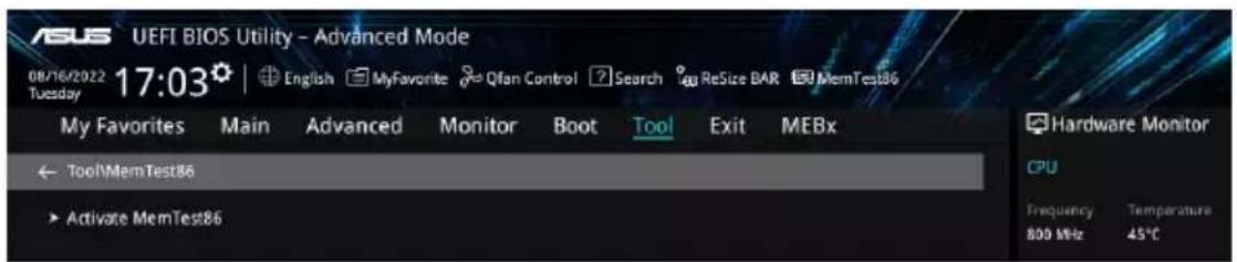
Activate MemTest86
Press Enter to open MemTest86 to perform and check testing results.

- Please save all changes made before using MemTest86.
- There will be a few seconds of loading time after pressing on this option.
4.9 Exit menu
The Exit menu items allow you to load the optimal default values for the BIOS items, and save or discard your changes to the BIOS items. You can access the EZ Mode from the Exit menu.

Load Optimized Defaults
Allows you to load the default values for each of the parameters on the Setup menus. When you select this option or if you press , a confirmation window appears. Select OK to load the default values.
Save Changes & Reset
Once you are finished making your selections, choose this option from the Exit menu to ensure the values you selected are saved. When you select this option or if you press , a confirmation window appears. Select OK to save changes and exit.
Discard Changes & Exit
Allows you to exit the Setup program without saving your changes. When you select this option or if you press , a confirmation window appears. Select Yes to discard changes and exit.
Launch EFI Shell from USB drives
Allows you to attempt to launch the EFI Shell application (Shell.efi) from one of the available filesystem devices.
4.10 Updating BIOS
The ASUS website publishes the latest BIOS versions to provide enhancements on system stability, compatibility, and performance. However, BIOS updating is potentially risky. If there is no problem using the current version of BIOS, DO NOT manually update the BIOS. Inappropriate BIOS updating may result in system's failure to boot. Carefully follow the instructions in this chapter to update your BIOS when necessary.

Visit http://www.asus.com to download the latest BIOS file for this motherboard.
The following utilities allow you to manage and update the motherboard BIOS setup program.
- EZ Update: Updates the BIOS in Windows environment.
- ASUS EZ Flash 3: Updates the BIOS using a USB flash drive.
- ASUS CrashFree BIOS 3: Restores the BIOS using the motherboard support DVD or a USB flash drive when the BIOS file fails or gets corrupted.
4.10.1 EZ Update
The EZ Update is a utility that allows you to update the motherboard BIOS in Windows® environment.

- EZ Update requires an Internet connection either through a network or an ISP (Internet Service Provider).
- This utility is available in the support DVD that comes with the motherboard package.
4.10.2 ASUS EZ Flash 3
ASUS EZ Flash 3 allows you to download and update to the latest BIOS using a USB drive.
To update the BIOS:
- Insert the USB flash drive that contains the latest BIOS file to a USB port.
- Enter the Advanced Mode of the BIOS setup program. Go to the Tool menu to select ASUS EZ Flash 3 Utility and press <Enter>.
- Press Left arrow key to switch to the Drive field.
- Press the Up/Down arrow keys to find the USB flash drive that contains the latest BIOS, and then press <Enter>.
- Press Right arrow key to switch to the Folder Info field.
- Press the Up/Down arrow keys to find the BIOS file, and then press <Enter> to perform the BIOS update process. Reboot the system when the update process is done.
![ASUS UEFI BIOS Utility - Advanced Mode ASUS EZ Flash 3 Utility v03.00 Flash Model: W680/SYS Version: 0201 Date: 12/09/2021 File Path: fs0:\ Drive Folder Storage Device(s) 03/02/2022 17:43 33558528 W680-SYS-ASUS-0205.CAP fs0:\ [3825 WB] 03/03/2096 17:25 System Volume Information](/content/2026/05/981869/images/81a3959a54b944e8c7993f49880049cd7705d772d679d2abb478c0b8ea878c81.jpg)
4.10.3 ASUS CrashFree BIOS 3
The ASUS CrashFree BIOS 3 utility is an auto recovery tool that allows you to restore the BIOS file when it fails or gets corrupted during the updating process. You can restore a corrupted BIOS file using the motherboard support DVD or a USB flash drive that contains the BIOS file.

The BIOS file in the motherboard support DVD may be older than the BIOS file published on the ASUS official website. If you want to use the newer BIOS file, download the file at https://www.asus.com/support/ and save it to a USB flash drive.
Recovering the BIOS
To recover the BIOS:
- Turn on the system.
- Insert the motherboard support DVD to the optical drive, or the USB flash drive containing the BIOS file to the USB port.
- The utility automatically checks the devices for the BIOS file. When found, the utility reads the BIOS file and enters ASUS EZ Flash 3 automatically.
- The system requires you to enter BIOS Setup to recover the BIOS setting. To ensure system compatibility and stability, we recommend that you press to load default BIOS values.

DO NOT shut down or reset the system while updating the BIOS! Doing so can cause system boot failure!
RAID Configuration
This chapter provides instructions for setting up, creating, and configuring RAID sets using the available utilities.
5
5.1 RAID configurations
The motherboard supports Intel® Rapid Storage Technology enterprise Option ROM Utility with RAID 0, RAID 1, RAID 10, and RAID 5 support.

If you want to install a Windows® operating system to a hard disk drive included in a RAID set, you have to create a RAID driver disk and load the RAID driver during OS installation. Refer to section Creating a RAID driver disk for details.
5.1.1 RAID definitions
RAID 0 (Data striping) optimizes two identical hard disk drives to read and write data in parallel, interleaved stacks. Two hard disks perform the same work as a single drive but at a sustained data transfer rate, double that of a single disk alone, thus improving data access and storage. Use of two new identical hard disk drives is required for this setup.
RAID 1 (Data mirroring) copies and maintains an identical image of data from one drive to a second drive. If one drive fails, the disk array management software directs all applications to the surviving drive as it contains a complete copy of the data in the other drive. This RAID configuration provides data protection and increases fault tolerance to the entire system. Use two new drives or use an existing drive and a new drive for this setup. The new drive must be of the same size or larger than the existing drive.
RAID 5 stripes both data and parity information across three or more hard disk drives. Among the advantages of RAID 5 configuration include better HDD performance, fault tolerance, and higher storage capacity. The RAID 5 configuration is best suited for transaction processing, relational database applications, enterprise resource planning, and other business systems. Use a minimum of three identical hard disk drives for this setup.
RAID 10 is data striping and data mirroring combined without parity (redundancy data) having to be calculated and written. With the RAID 10 configuration you get all the benefits of both RAID 0 and RAID 1 configurations. Use four new hard disk drives or use an existing drive and three new drives for this setup.
5.1.2 Installing storage devices
The motherboard supports Serial ATA hard disk drives, PCIE SSD storage devices, and M.2 modules. For optimal performance, install identical drives or modules of the same model and capacity when creating a disk array.

Refer to Chapter 2 for details on installing storage devices to your motherboard.
5.1.3 Creating a SATA RAID set in UEFI BIOS
- Enter the BIOS Setup during POST.

Refer to Chapter 4 in your motherboard's user manual for details on entering and navigating through the BIOS Setup.
- Go to Advanced > System Agent (SA) Configuration > VMD Setup Menu.

- In the VMD setup menu, set Enable VMD controller and Map SATA Controller under VMD to [Enabled], and set Map PCIE Storage under VMD to [Disabled].

- Save your changes and exit the BIOS Setup, then enter the BIOS Setup again.
- Go to Advanced > Intel(R) Rapid Storage Technology to display the Intel® Rapid Storage Technology menu.
Creating a RAID set
- From the Intel® Rapid Storage Technology menu, select Create RAID Volume and press <Enter>. The following screen appears:

- When the Name item is selected, enter a name for the RAID set and press .
- When the RAID Level item is selected, press to select the RAID level to create, and then press .
- Under Select Disks, press and select X for the disks you want to include in the RAID set.
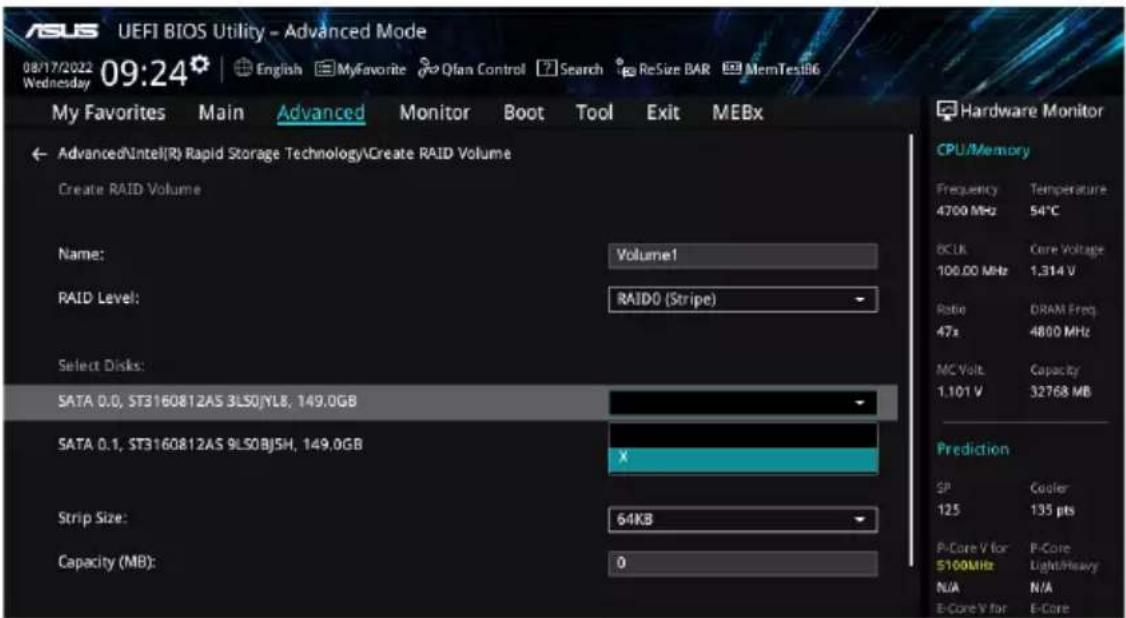
- When the Strip Size item is selected, press to select strip size for the RAID array (for RAID 0, 10 and 5 only), and then press . The available strip size values range from 4 KB to 128 KB. The following are typical values:
- RAID 0: 128 KB
- RAID 10: 64 KB
- RAID 5: 64 KB

We recommend a lower strip size for server systems, and a higher strip size for multimedia computer systems used mainly for audio and video editing.

- When the Capacity (MB) item is selected, enter the RAID volume capacity that you want and press . The default value indicates the maximum allowed capacity.
- When the Create Volume item is selected, press to create the RAID volume and return to the Intel® Rapid Storage Technology menu.

- Save your changes and exit the BIOS Setup, then enter the BIOS Setup again.
- The RAID volume should appear in the Intel(R) Rapid Storage Technology menu, And also appear in the EZ Mode menu under Storage Information.

To delete a RAID set, please refer to section Deleting a RAID set.
5.1.4 Creating an NVMe RAID set with onboard M.2 modules in UEFI BIOS

- You can create a RAID set with the following setups:
- NVMe SSDs from the CPU.
- NVMe SSDs from the PCH.
- NVMe SSDs from the CPU and PCH.
- Third-party storage devices.
- You can only create PCIe RAID 0/1/5 on W680/Z690/Q670/H670 Series
- Enter the BIOS Setup during POST.

Refer to Chapter 4 in your motherboard's user manual for details on entering and navigating through the BIOS Setup.
- Go to Advanced > System Agent (SA) Configuration > VMD Setup Menu.

- In the VMD setup menu, set Enable VMD controller and Map PCIE Storage under VMD to [Enabled], and set Map SATA Controller under VMD to [Disabled].

- Save your changes and exit the BIOS Setup, then enter the BIOS Setup again.
- Go to Advanced > Intel(R) Rapid Storage Technology to display the Intel® Rapid Storage Technology menu.
Creating a RAID set
- From the Intel® Rapid Storage Technology menu, select Create RAID Volume and press Enter. The following screen appears:

- When the Name item is selected, enter a name for the RAID set and press Enter.
- When the RAID Level item is selected, press Enter to select the RAID level to create, and then press Enter.
- Under Select Disks, press Enter and select X for the disks you want to include in the RAID set.

Only full SATA or full NVMe RAID is supported, different interfaces of RAID cannot be created, such as half NVMe and half RAID.
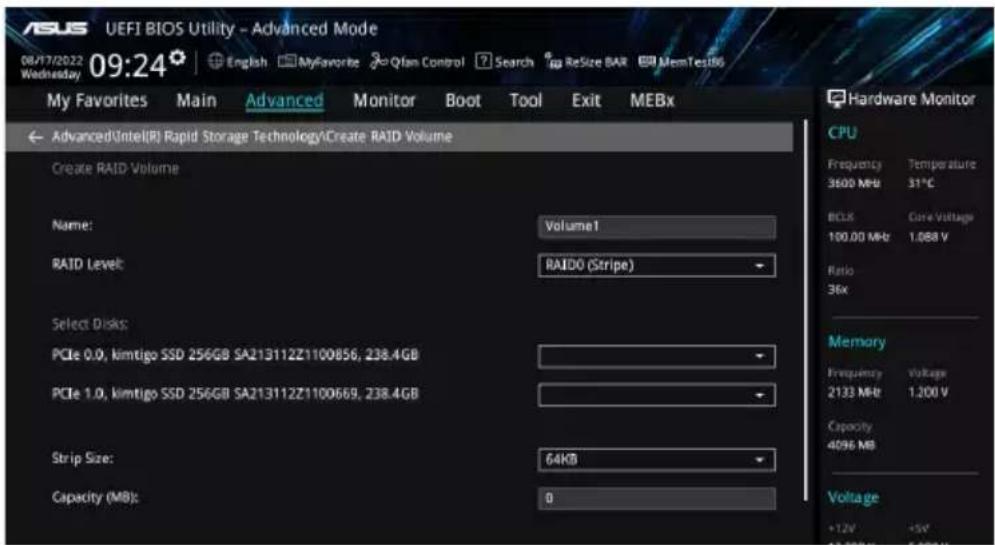
- When the Strip Size item is selected, press Enter to select strip size for the RAID array (for RAID 0, 10 and 5 only), and then press Enter. The available strip size values range from 4 KB to 128 KB. The following are typical values:
- RAID 0: 128 KB
- RAID 10: 64 KB
- RAID 5: 64 KB

We recommend a lower strip size for server systems, and a higher strip size for multimedia computer systems used mainly for audio and video editing.
- When the Capacity (MB) item is selected, enter the RAID volume capacity that you want and press [Enter]. The default value indicates the maximum allowed capacity.
- When the Create Volume item is selected, press [Enter] to create the RAID volume and return to the Intel® Rapid Storage Technology menu.

- Save your changes and exit the BIOS Setup, then enter the BIOS Setup again.
- The RAID volume should appear in the Intel(R) Rapid Storage Technology menu, and also appear in the EZ Mode menu under Storage Information.

To delete a RAID set, please refer to section Deleting a RAID set.
5.1.5 Deleting a RAID set

Be cautious when deleting a RAID set. You will lose all data on the hard disk drives when you delete a RAID set.
To delete a RAID set:
- From the Intel® Rapid Storage Technology menu, select the RAID volume you want to delete and press [Enter]. The following screen appears:

- When the Delete item is selected, press [Enter], then select Yes to delete the RAID volume and return to the Intel® Rapid Storage Technology menu, or select No to cancel.

5.2 Installing the RAID controller driver during Windows® 10 or Windows® 11 OS installation
After creating the RAID sets, you are now ready to install an operating system to the independent drives or bootable array. This part provides the instructions on how to install the RAID controller drivers during OS installation.

The steps and screenshots are for reference only and may change with newer Windows updates.

If you created a SATA RAID set, you will not be able to use the optical drive connected to a SATA port before the RAID driver is loaded.
To install the RAID controller driver when installing Windows 10 or Windows 11 OS:
- Boot the computer using the Windows 10 OS or Windows 11 installation disc. Follow the screen instructions to start installing Windows.
- When prompted to choose a type of installation, click Custom: Install Windows only (advanced).

- Click Load Driver.

- A message appears, reminding you to insert the installation media containing the driver of the RAID controller driver. Click Browse to continue.

- If you have only one optical drive installed in your system, eject the Windows OS installation disc and replace it with the motherboard Support DVD.
- If you created a SATA RAID set and cannot use the optical drive, or if you do not have an optical drive, you can use another computer with an optical drive to copy the RAID driver from the support DVD to a USB flash drive.

- Locate the driver in the corresponding folder of the Support DVD or the USB flash drive with RAID driver, then click OK to continue.
- Select the RAID controller driver you need from the list and click Next.
- When the system finishes loading the RAID driver, select the drive to install Windows and click Next.

If you have ejected the Windows OS installation disc in a previous step, ensure to replace the motherboard Support DVD with the Windows OS installation disc.
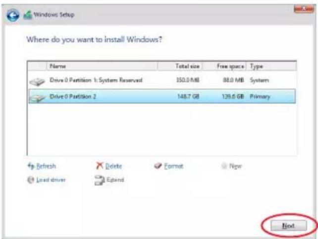
- Setup then proceeds with the OS installation. Follow screen instructions to complete.
Appendix

W680/SYS block diagram![graph TD A["128-bit Dual-Channel Memory x 4 Slots"] --> B["Intel Processor"] B --> C["Alder Lake - S (6+0 or 8+8) LGA-1700 Pin Socket"] C --> D["Channel A: DDR5 4800"] C --> E["Channel B: DDR5 4800"] C --> F["DOI A: VGA"] C --> G["DOI B: HDMI"] C --> H["DOI C: DP"] C --> I["DOI D: DV1"] B --> J["PCI…](/content/2026/05/981869/images/b6302d7499dbefd4705cd500355778fded0cc69656702aa8a1365dd822df4a63.jpg)
Q-Code table
| Code Description | |
| 00 | Not used |
| 02 | microcode |
| 03 | CACHE_ENABLED |
| 04 | PCH initialization |
| 06 | CPU_EARLY_INIT |
| 10 | PEI Core is started |
| 11 – 14 | Pre-memory CPU initialization is started |
| 15 – 18 | Pre-memory System Agent initialization is started |
| 19 – 1C | Pre-memory PCH initialization is started |
| 2B – 2F | Memory initialization |
| 30 | Reserved for ASL (see ASL Status Codes section below) |
| 31 | Memory Installed |
| 32 – 36 | CPU post-memory initialization |
| 37 – 3A | Post-Memory System Agent initialization is started |
| 3B – 3E | Post-Memory PCH initialization is started |
| 4F | DXE IPL is started |
| 50 – 53 | Memory initialization error. Invalid memory type or incompatible memory speed |
| 4F | DXE IPL is started |
| 54 | Unspecified memory initialization error |
| 55 | Memory not installed |
| 56 | Invalid CPU type or Speed |
| 57 | CPU mismatch |
| 58 | CPU self test failed or possible CPU cache error |
| 59 | CPU micro-code is not found or micro-code update is failed |
| 5A | Internal CPU error |
| 5B | Reset PPI is not available |
| 5C – 5F | Reserved for future AMI error codes |
| E0 | S3 Resume is stared (S3 Resume PPI is called by the DXE IPL) |
| E1 | S3 Boot Script execution |
| E2 | Video repost |
| E3 | OS S3 wake vector call |
| E4 – E7 | Reserved for future AMI progress codes |
| E8 | S3 Resume Failed |
| E9 | S3 Resume PPI not Found |
| EA | S3 Resume Boot Script Error |
| EB | S3 OS Wake Error |
| EC – EF | Reserved for future AMI error codes |
| F0 | Recovery condition triggered by firmware (Auto recovery) |
| F1 | Recovery condition triggered by user (Forced recovery) |
| F2 | Recovery process started |
| F3 | Recovery firmware image is found |
(continued on the next page)
| Code Description | |
| F4 | Recovery firmware image is loaded |
| F5 – F7 | Reserved for future AMI progress codes |
| F8 | Recovery PPI is not available |
| F9 | Recovery capsule is not found |
| FB – FF | Reserved for future AMI error codes |
| 60 | DXE Core is started |
| 61 | NVRAM initialization |
| 62 | Installation of the PCH Runtime Services |
| 63 – 67 | CPU DXE initialization is started |
| 68 | PCI host bridge initialization |
| 69 | System Agent DXE initialization is started |
| 6A | System Agent DXE SMM initialization is started |
| 6B – 6F | System Agent DXE initialization (System Agent module specific) |
| 70 | PCH DXE initialization is started |
| 71 | PCH DXE SMM initialization is started |
| 72 | PCH devices initialization |
| 73 – 77 | PCH DXE Initialization (PCH module specific) |
| 78 | ACPI module initialization |
| 79 | CSM initialization |
| 7A – 7F | Reserved for future AMI DXE codes |
| 90 | Boot Device Selection (BDS) phase is started |
| 91 | Driver connecting is started |
| 92 | PCI Bus initialization is started |
| 93 | PCI Bus Hot Plug Controller Initialization |
| 94 | PCI Bus Enumeration |
| 95 | PCI Bus Request Resources |
| 96 | PCI Bus Assign Resources |
| 97 | Console Output devices connect |
| 98 | Console input devices connect |
| 99 | Super IO Initialization |
| 9A | USB initialization is started |
| 9B | USB Reset |
| 9C | USB Detect |
| 9D | USB Enable |
| 9E – 9F | Reserved for future AMI codes |
| A0 | IDE initialization is started |
| A1 | IDE Reset |
| A2 | IDE Detect |
| A3 | IDE Enable |
| A4 | SCSI initialization is started |
(continued on the next page)
| Code Description | |
| A5 | SCSI Reset |
| A6 | SCSI Detect |
| A7 | SCSI Enable |
| A8 | Setup Verifying Password |
| A9 | Start of Setup |
| AA | Reserved for ASL (see ASL Status Codes section below) |
| AB | Setup Input Wait |
| AC | Reserved for ASL (see ASL Status Codes section below) |
| AD | Ready To Boot event |
| AE | Legacy Boot event |
| AF | Exit Boot Services event |
| B0 | Runtime Set Virtual Address MAP Begin |
| B1 | Runtime Set Virtual Address MAP End |
| B2 | Legacy Option ROM Initialization |
| B3 | System Reset |
| B4 | USB hot plug |
| B5 | PCI bus hot plug |
| B6 | Clean-up of NVRAM |
| B7 | Configuration Reset (reset of NVRAM settings) |
| B8-BF | Reserved for future AMI codes |
| D0 | CPU initialization error |
| D1 System Agent initialization error | |
| D2 | PCH initialization error |
| D3 | Some of the Architectural Protocols are not available |
| D4 | PCI resource allocation error. Out of Resources |
| D5 | No Space for Legacy Option ROM |
| D6 | No Console Output Devices are found |
| D7 | No Console Input Devices are found |
| D8 | Invalid password |
| D9 | Error loading Boot Option (LoadImage returned error) |
| DA | Boot Option is failed (StartImage returned error) |
| DB | Flash update is failed |
| DC | Reset protocol is not available |
ACPI/ASL Checkpoints (under OS)
| Code Description | |
| 03 | System is entering S3 sleep state |
| 04 | System is entering S4 sleep state |
| 05 | System is entering S5 sleep state |
| 30 | System is waking up from the S3 sleep state |
| 40 | System is waking up from the S4 sleep state |
| AC | System has transitioned into ACPI mode. Interrupt controller is in PIC mode. |
| AA | System has transitioned into ACPI mode. Interrupt controller is in APIC mode. |
Notices
FCC Compliance Information
Responsible Party: Asus Computer International
Address: 48720 Kato Rd., Fremont, CA 94538, USA
Phone / Fax No: (510)739-3777 / (510)608-4555
This device complies with part 15 of the FCC Rules. Operation is subject to the following two conditions: (1) This device may not cause harmful interference, and (2) this device must accept any interference received, including interference that may cause undesired operation. This equipment has been tested and found to comply with the limits for a Class B digital device, pursuant to part 15 of the FCC Rules. These limits are designed to provide reasonable protection against harmful interference in a residential installation. This equipment generates, uses and can radiate radio frequency energy and, if not installed and used in accordance with the instructions, may cause harmful interference to radio communications. However, there is no guarantee that interference will not occur in a particular installation. If this equipment does cause harmful interference to radio or television reception, which can be determined by turning the equipment off and on, the user is encouraged to try to correct the interference by one or more of the following measures:
- Reorient or relocate the receiving antenna.
- Increase the separation between the equipment and receiver.
- Connect the equipment into an outlet on a circuit different from that to which the receiver is connected.
- Consult the dealer or an experienced radio/TV technician for help.

The use of shielded cables for connection of the monitor to the graphics card is required to assure compliance with FCC regulations. Changes or modifications to this unit not expressly approved by the party responsible for compliance could void the user's authority to operate this equipment.
End Product Labeling
This transmitter module is authorized only for use in device where the antenna may be installed such that 20cm may be maintained between the antenna and users. The final end product must be labeled in a visible area with the following: "Contains FCC ID: PD9AX210NG" and "Contains IC: 1000M-AX210NG".
This radio transmitter FCCID: PD9AX210NG has been approved by FCC to operate with the antenna types listed below with the maximum permissible gain and required antenna impedance for each antenna type indicated. Antenna types not included in this list, having a gain greater than the maximum gain indicated for that type, are strictly prohibited for use with this device.
Antenna List:
| No. | Manufacturer P | Part No. Antenna Type Peak | Gain | |
| 1 | Inpaq DAM-I3-H1 | -M2-800-10-66 Dipole antenna | 2.73dBi for 2.4GHz | 1.79dBi for 5GHz |
NOTE: The antenna connector is Reverse SMA type.
RF exposure warning
This equipment must be installed and operated in accordance with provided instructions and the antenna(s) used for this transmitter must be installed to provide a separation distance of at least 20 cm from all persons and must not be co-located or operating in conjunction with any other antenna or transmitter. End-users and installers must be provide with antenna installation instructions and transmitter operating conditions for satisfying RF exposure compliance.
HDMI Trademark Notice
The terms HDMI, HDMI High-Definition Multimedia Interface, and the HDMI Logo are trademarks or registered trademarks of HDMI Licensing Administrator, Inc.
Compliance Statement of Innovation, Science and Economic Development Canada (ISED)
This device complies with Innovation, Science and Economic Development Canada licence exempt RSS standard(s). Operation is subject to the following two conditions: (1) this device may not cause interference, and (2) this device must accept any interference, including interference that may cause undesired operation of the device.
Operation in the band 5150–5250 MHz is only for indoor use to reduce the potential for harmful interference to co-channel mobile satellite systems.
CAN ICES-003(B)/NMB-003(B)
Users should also be advised that high-power radars are allocated as primary users (i.e. priority users) of the bands 5250-5350 MHz and 5650-5850 MHz and that these radars could cause interference and/or damage to LE-LAN devices.
Radio Frequency (RF) Exposure Information
The radiated output power of the Wireless Device is below the Innovation, Science and Economic Development Canada (ISED) radio frequency exposure limits. The Wireless Device should be used in such a manner such that the potential for human contact during normal operation is minimized.
This device has also been evaluated and shown compliant with the ISED RF Exposure limits under mobile exposure conditions. (antennas are greater than 20cm from a person's body).
This radio transmitter IC: 1000M-AX210NG has been approved by Innovation, Science and Economic Development Canada to operate with the antenna types listed below, with the maximum permissible gain indicated. Antenna types not included in this list that have a gain greater than the maximum gain indicated for any type listed are strictly prohibited for use with this device.
| No. | Manufacturer P | Part No. Antenna Type Peak | Gain | |
| 1 In | baq DAM-I3-H1 | -M2-800-10-66 Dipole anter | na 2.73dBi for 2.4GHz | 1.79dBi for 5GHz |
NOTE: The antenna connector is Reverse SMA type.
VCCI: Japan Compliance Statement
Class B ITE
This product cannot be directly connected to the Internet (including public wireless LAN) of a telecom carrier (mobile network companies, landline network companies, Internet providers, etc.). When connecting this product to the Internet, be sure to connect it through a router or switch.
Japan JATE
Accessories that came with this product have been designed and verified for the use in connection with this product. Never use accessories for other products to prevent the risk of electric shock or fire.
Safety Precautions
KC: Korea Warning Statement
Class B Equipment (Home Broadcasting and Communication Equipment)
NCC Wireless Statement
Japan RF Equipment Statement
For outdoor use
Copyright© 2022 Google Inc. All Rights Reserved.
Licensed under the Apache License, Version 2.0 (the "License"); you may not use this file except in compliance with the License. You may obtain a copy of the License at: http://www.apache.org/licenses/LICENSE-2.0
Unless required by applicable law or agreed to in writing, software distributed under the License is distributed on an “AS IS” BASIS, WITHOUT WARRANTIES OR CONDITIONS OF ANY KIND, either express or implied.
See the License for the specific language governing permissions and limitations under the License.
Australia statement notice
From 1 January 2012 updated warranties apply to all ASUS products, consistent with the Australian Consumer Law. For the latest product warranty details please visit https://www.asus.com/support/. Our goods come with guarantees that cannot be excluded under the Australian Consumer Law. You are entitled to a replacement or refund for a major failure and compensation for any other reasonably foreseeable loss or damage. You are also entitled to have the goods repaired or replaced if the goods fail to be of acceptable quality and the failure does not amount to a major failure.
If you require assistance please call ASUS Customer Service 1300 2787 88 or visit us at https://www.asus.com/support/.
Regional notice for Singapore
Complies with IMDA Standards DA106775
This ASUS product complies with IMDA Standards.
Declaration of compliance for product environmental regulation
ASUS follows the green design concept to design and manufacture our products, and makes sure that each stage of the product life cycle of ASUS product is in line with global environmental regulations. In addition, ASUS disclose the relevant information based on regulation requirements.
Please refer to http://csr.asus.com/Compliance.htm for information disclosure based on regulation requirements ASUS is complied with:
EU REACH and Article 33
Complying with the REACH (Registration, Evaluation, Authorization, and Restriction of Chemicals) regulatory framework, we publish the chemical substances in our products at ASUS REACH website at http://csr.asus.com/english/REACH.htm.
EU RoHS
This product complies with the EU RoHS Directive. For more details, see http://csr.asus.com/english/article.aspx?id=35
Japan JIS-C-0950 Material Declarations
Information on Japan RoHS (JIS-C-0950) chemical disclosures is available on http://csr.asus.com/english/article.aspx?id=19
India RoHS
This product complies with the “India E-Waste (Management) Rules, 2016” and prohibits use of lead, mercury, hexavalent chromium, polybrominated biphenyls (PBBs) and polybrominated diphenyl ethers (PBDEs) in concentrations exceeding 0.1% by weight in homogenous materials and 0.01% by weight in homogenous materials for cadmium, except for the exemptions listed in Schedule II of the Rule.
Vietnam RoHS
ASUS products sold in Vietnam, on or after September 23, 2011, meet the requirements of the Vietnam Circular 30/2011/TT-BCT.
ASUS recycling and takeback programs come from our commitment to the highest standards for protecting our environment. We believe in providing solutions for you to be able to responsibly recycle our products, batteries, other components as well as the packaging materials. Please go to http://csr.asus.com/english/Takeback.htm for detailed recycling information in different regions.
Ecodesign Directive
The European Union announced a framework for setting ecodesign requirements for energy-related products (2009/125/EC). Specific implementing measures aim to improve the environmental performance of specific products or across multiple product types. ASUS provides product information on the CSR website. Further information can be found at https://csr.asus.com/english/article.aspx?id=1555.

Do not throw the motherboard in municipal waste. This product has been designed to enable proper reuse of parts and recycling. This symbol of the crossed-out wheeled bin indicates that the product (electrical and electronic equipment) should not be placed in municipal waste. Check local regulations for disposal of electronic products.

Do not throw the mercury-containing button cell battery in municipal waste. This symbol of the crossed-out wheeled bin indicates that the battery should not be placed in municipal waste.
ENERGY STAR® Qualified Product

ENERGY STAR® is a joint program of the U.S. Environmental Protection Agency and the U.S. Department of Energy, helping us all save money and protect the environment through energy-efficient products and practices.
All ASUS products with the ENERGY STAR® logo comply with the ENERGY STAR® standard, and the power management feature is enabled by default. The monitor is automatically set to sleep within 10 minutes of
user inactivity; the computer is automatically set to sleep within 30 minutes of user inactivity. To wake your computer, click the mouse, press any key on the keyboard, or press the power button.
Please visit http://www.energystar.gov/powermanagement for detailed information on power management and its benefits to the environment. In addition, please visit http://www.energystar.gov for detailed information on the ENERGY STAR® joint program.

ENERGY STAR® is NOT supported on FreeDOS and Linux-based operating systems.
Simplified UKCA Declaration of Conformity
ASUSTek Computer Inc. hereby declares that this device is in compliance with the essential requirements and other relevant provisions of The Radio Equipment Regulations 2017 (S.I. 2017/1206). The full text of the UKCA declaration of conformity is available at https://www.asus.com/support/.
The WiFi operating in the band 5150-5350MHz shall be restricted to indoor use for the country listed below:
UK
UKCA RF Output table (The Radio Equipment Regulations 2017)
Intel® Wi-Fi 6E AX210 (Model: AX210NGW):
a. Low Power Indoor (LPI) Wi-Fi 6E devices: The device is restricted to indoor use only when operating in the 5925 to 6425 MHz frequency range in UK. b. Very Low Power (VLP) Wi-Fi 6E devices (portable devices): The device is not permitted to be used on Unmanned Aircraft Systems (UAS) when operating in the 5925 to 6425 MHz frequency range in UK.
| Function Frequency Maximum Output Power (EIRP) | |
| WiFi | 2412 - 2472 MHz 19.39 dBm |
| 5150 - 5350 MHz 19.17 dBm | |
| 5470 - 5725 MHz 18.47 dBm | |
| 5725 - 5850 MHz 10.09 dBm | |
| 5925 - 6425 MHz 20.42 dBm | |
| Bluetooth 2402 - 2480 MHz 12.62 dBm | |
* Receiver category 1

UKCA RF Output table (The Radio Equipment Regulations 2017)
Intel® Wi-Fi 6E AX211 (Model: AX212NGW):
| Function Frequency Maximum Output Power (EIRP) | |
| WiFi | 2412 - 2472 MHz 19.39 dBm |
| 5150 - 5350 MHz 19.17 dBm | |
| 5470 - 5725 MHz 18.47 dBm | |
| 5725 - 5850 MHz 10.09 dBm | |
| 5925 - 6425 MHz 20.42 dBm | |
| Bluetooth 2402 - 2480 MHz 12.62 dBm | |
* Receiver category 1

Simplified EU Declaration of Conformity
ASUSTek Computer Inc. hereby declares that this device is in compliance with the essential requirements and other relevant provisions of Directive 2014/53/EU. Full text of EU declaration of conformity is available at https://www.asus.com/support/.
The WiFi operating in the band 5150-5350MHz shall be restricted to indoor use for countries listed in the table below:
a. Low Power Indoor (LPI) Wi-Fi 6E devices: The device is restricted to indoor use only when operating in the 5945 to 6425 MHz frequency range in Belgium (BE), Bulgaria (BG), Cyprus (CY), Czech Republic (CZ), Estonia (EE), France (FR), Iceland (IS), Ireland (IE), Lithuania (LT), Germany (DE), Netherlands (NL), Spain (ES).
b. Very Low Power (VLP) Wi-Fi 6E devices (portable devices): The device is not permitted to be used on Unmanned Aircraft Systems (UAS) when operating in the 5945 to 6425 MHz frequency range in Belgium (BE), Bulgaria (BG), Cyprus (CY), Czech Republic (CZ), Estonia (EE), France (FR), Iceland (IS), Ireland (IE), Lithuania (LT), Germany (DE), Netherlands (NL), Spain (ES).
https://www.asus.com/support/.
* Receiver category 1
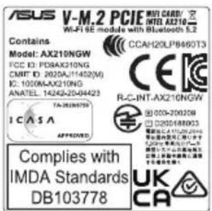
CE RED RF Output table (Directive 2014/53/EU)
Intel™ Wi-Fi 6E AX211 (Model: AX211NGW):
| Function Frequency Maximum Output Power (EIRP) | |
| WiFi | 2412 - 2472 MHz 19.39 dBm |
| 5150 - 5350 MHz 19.17 dBm | |
| 5470 - 5725 MHz 18.47 dBm | |
| 5725 - 5850 MHz 10.09 dBm | |
| 5925 - 6425 MHz 20.42 dBm | |
| Bluetooth 2402 - 2480 MHz 12.62 dBm | |
* Receiver category 1

Warranty
ASUS Guarantee Information
ASUS offers a voluntary manufacturer's Commercial Guarantee. ASUS reserves the right to interpret the provisions of the ASUS Commercial Guarantee. This ASUS Commercial Guarantee is provided independently and in addition to the statutory Legal Guarantee and in no way affects or limits the rights under the Legal Guarantee.
For all guarantee information, please visit https://www.asus.com/support.
ASUS Warranty
https://www.asus.com/vn/support

Service and Support
Visit our multi-language website at https://www.asus.com/support.


- COPYRIGHT © 2023 ASUSTEK COMPUTER INC. ALL RIGHTS RESERVED
- CONTENTS
- CHAPTER 1: PRODUCT INTRODUCTION
- CHAPTER 2: HARDWARE SETUP
- CHAPTER 3: MOTHERBOARD INFORMATION
- CHAPTER 4: BIOS SETUP
- TOOL MENU
- EXIT MENU
- UPDATING BIOS
- CHAPTER 5: RAID CONFIGURATION
- RAID CONFIGURATIONS
- INSTALLING THE RAID CONTROLLER DRIVER DURING WINDOWS 10 OR WINDOWS 11 OS INSTALLATION
- APPENDIX
- SAFETY INFORMATION
- ELECTRICAL SAFETY
- OPERATION SAFETY
- LITHIUM-ION BATTERY WARNING
- HEAVY SYSTEM
- ABOUT THIS GUIDE
- AUDIENCE
- CONVENTIONS USED IN THIS GUIDE
- TYPOGRAPHY
- BOLD TEXT
- COMMAND
- REFERENCES
- ASUS WEBSITES
- PRODUCT INTRODUCTION
- SYSTEM PACKAGE CONTENTS
- SERIAL NUMBER LABEL
- E500 G9 SPECIFICATIONS SUMMARY
- FRONT PANEL FEATURES
- REAR PANEL FEATURES
- INTERNAL FEATURES
- WARNING
- LED INFORMATION
- FRONT PANEL LEDS
- REAR PANEL LEDS
- HARDWARE SETUP
- CHASSIS COVER
- REMOVING THE SIDE COVER
- CPU INSTALLATION
- COOLING SYSTEM INSTALLATION
- SYSTEM MEMORY
- RECOMMENDED MEMORY CONFIGURATIONS
- MEMORY CONFIGURATIONS
- INSTALLING A DIMM ON A SINGLE CLIP DIMM SOCKET
- REMOVING A DIMM FROM A SINGLE CLIP DIMM SOCKET
- FRONT PANEL COVER
- REMOVING THE FRONT PANEL COVER
- INCH DRIVES
- INSTALLING A 5.25-INCH DRIVE
- HARD DISK DRIVES (HDD)
- INSTALLING 3.5-INCH HDDS
- INSTALLING 2.5-INCH HDD/SSD
- EXPANSION SLOTS
- INSTALLING AN EXPANSION CARD
- CONFIGURING AN EXPANSION CARD
- INSTALLING M.2 (NGFF) CARDS
- INSTALLING AN M.2 FAN (OPTIONAL)
- SYSTEM FAN
- BIOS UPDATE UTILITY
- USB BIOS FLASHBACK™
- TO USE USB BIOS FLASHBACK™
- MOTHERBOARD REAR AND AUDIO CONNECTION
- REAR I/O CONNECTION
- AUDIO I/O CONNECTIONS
- MOTHERBOARD INFORMATION
- ONBOARD BUTTONS AND SWITCHES
- POWER-ON BUTTON
- RESET BUTTON
- JUMPERS
- CLEAR RTC RAM HEADER
- TO ERASE THE RTC RAM
- LPT AND Q-CODE JUMPER
- CPU OVER VOLTAGE JUMPER
- ONBOARD LEDS
- Q LED (CPU, DRAM, VGA, BOOT)
- USB BIOS FLASHBACK™ LED
- STANDBY POWER LED
- Q-CODE LED
- PIN POWER PLUG LED
- INTERNAL CONNECTORS
- INTEL® SERIAL ATA 6 GB/S CONNECTORS
- FRONT PANEL AUDIO CONNECTOR
- TPM CONNECTOR
- USB 3.2 GEN 2X2 TYPE-C® FRONT PANEL CONNECTOR
- USB 3.2 GEN 1 CONNECTOR
- USB 2.0 CONNECTORS
- SERIAL PORT CONNECTOR
- FAN CONNECTORS
- DIGITAL AUDIO CONNECTOR
- SYSTEM PANEL CONNECTOR
- SYSTEM POWER LED (2-PIN OR 3-1 PIN PLED)
- HARD DISK DRIVE ACTIVITY LED (2-PIN HDD_LED)
- SYSTEM WARNING SPEAKER (4-PIN SPEAKER)
- ATX POWER BUTTON/SOFT-OFF BUTTON (2-PIN PWRSW)
- RESET BUTTON (2-PIN RESET)
- CHASSIS INTRUSION CONNECTOR (2-PIN CHASSIS)
- ATX POWER CONNECTORS
- M.2 SOCKETS
- M.2 SLOT (KEY E)
- LPT CONNECTOR
- THERMAL SENSOR CONNECTOR
- THUNDERBOLT™ CONNECTOR (14-1 PIN TB_HEADER)
- BIOS SETUP
- INTRODUCTION TO THE BIOS
- BIOS SETUP PROGRAM
- ENTERING BIOS AT STARTUP
- ENTERING BIOS SETUP AFTER POST
- BIOS MENU SCREEN
- EZ MODE
- ADVANCED MODE
- MENU BAR
- MENU ITEMS
- SUBMENU ITEMS
- LANGUAGE
- MYFAVORITE
- QFAN CONTROL
- SEARCH
- RESIZE BAR
- MEMTEST
- HOT KEYS
- SCROLL BAR
- GENERAL HELP
- CONFIGURATION FIELDS
- LAST MODIFIED BUTTON
- Q-FAN CONTROL
- CONFIGURING FANS MANUALLY
- MY FAVORITES
- ADDING ITEMS TO MY FAVORITES
- MAIN MENU
- SECURITY
- ADMINISTRATOR PASSWORD
- TO SET AN ADMINISTRATOR PASSWORD
- TO CHANGE AN ADMINISTRATOR PASSWORD
- USER PASSWORD
- TO SET A USER PASSWORD
- TO CHANGE A USER PASSWORD
- ADVANCED MENU
- PLATFORM MISC CONFIGURATION
- PCI EXPRESS NATIVE POWER MANAGEMENT
- NATIVE ASPM
- PCH - PCI EXPRESS
- DMI LINK ASPM CONTROL
- ASPM
- L1 SUBSTATES
- SA - PCI EXPRESS
- DMI ASPM CONTROL
- DMI GEN3 ASPM
- PEG - ASPM
- PCI EXPRESS CLOCK GATING
- CPU CONFIGURATION
- EFFICIENT CORE INFORMATION
- PERFORMANCE CORE INFORMATION
- HARDWARE PREFETCHER
- ADJACENT CACHE LINE PREFETCH
- INTEL (VMX) VIRTUALIZATION TECHNOLOGY
- ACTIVE PERFORMANCE CORES
- ACTIVE EFFICIENT CORES
- HYPER-THREADING
- INTEL TRUSTED EXECUTION TECHNOLOGY
- ALIAS CHECK REQUEST
- DPR MEMORY SIZE (MB)
- RESET AUX CONTENT
- TOTAL MEMORY ENCRYPTION
- LEGACY GAME COMPATIBILITY MODE
- CPU - POWER MANAGEMENT CONTROL
- BOOT PERFORMANCE MODE
- INTEL(R) SPEEDSTEP(TM)
- INTEL(R) SPEED SHIFT TECHNOLOGY
- INTEL(R) TURBO BOOST MAX TECHNOLOGY
- TURBO MODE
- ACOUSTIC NOISE SETTINGS
- ACOUSTIC NOISE MITIGATION
- PRE WAKE TIME
- RAMP UP TIME
- RAMP DOWN TIME
- IA VR DOMAIN
- DISABLE FAST PKG C STATE RAMP FOR IA DOMAIN
- SLOW SLEW RATE FOR IA DOMAIN
- GT VR DOMAIN
- DISABLE FAST PKG C STATE RAMP FOR GT DOMAIN
- SLOW SLEW RATE FOR GT DOMAIN
- CPU C-STATES
- ENHANCED C-STATES
- PACKAGE C STATE LIMIT
- THERMAL MONITOR
- DUAL TAU BOOST
- SYSTEM AGENT (SA) CONFIGURATION
- VT-D
- CONTROL IOMMU PRE-BOOT BEHAVIOR
- MEMORY CONFIGURATION
- MEMORY REMAP
- GRAPHICS CONFIGURATION
- PRIMARY DISPLAY
- IGPU MULTI-MONITOR
- DVMT PRE-ALLOCATED
- RC6(RENDER STANDBY)
- VMD SETUP MENU
- ENABLE VMD CONTROLLER
- MAP PCIE STORAGE UNDER VMD
- MAP SATA CONTROLLER UNDER VMD
- PCI EXPRESS CONFIGURATION
- M.2_1 LINK SPEED
- PCIEX16(G5) LINK SPEED
- PCIEX16_2 LINK SPEED
- PCH CONFIGURATION
- PCIEX16(G3)_2 LINK SPEED
- M.2_2 LINK SPEED
- PCIEX16(G4)_4 LINK SPEED
- PCIEX16(G4)_3 LINK SPEED
- M.2_3 LINK SPEED
- PCH STORAGE CONFIGURATION
- SATA CONTROLLER(S)
- AGGRESSIVE LPM SUPPORT
- SMART SELF TEST
- SATA6G_1 - SATA6G
- SATA6G_1 - SATA6G_8 HOT PLUG
- PCH-FW CONFIGURATION
- PTT
- EXTEND CSME MEASUREMENT TO TPM-PCR
- AMT CONFIGURATION
- USB PROVISIONING OF AMT
- MAC PASS THROUGH
- ACTIVATE REMOTE ASSISTANCE PROCESS
- UNCONFIGURE ME
- ASF CONFIGURATION
- PET PROGRESS
- WATCHDOG
- OS TIMER
- BIOS TIMER
- ASF SENSORS TABLE
- SECURE ERASE CONFIGURATION
- SECURE ERASE MODE
- FORCE SECURE ERASE
- ONE CLICK RECOVERY (OCR) CONFIGURATION
- OCR HTTPS BOOT
- OCR PBA BOOT
- OCR WINDOWS RECOVERY BOOT
- OCR DISABLE SECURE BOOT
- THUNDERBOLT(TM) CONFIGURATION
- PCIE TUNNELING OVER USB
- DISCRETE THUNDERBOLT(TM) SUPPORT
- WAKE FROM THUNDERBOLT(TM) DEVICES
- DISCRETE THUNDERBOLT(TM) CONFIGURATION
- DTBT GO2SX COMMAND
- WINDOWS 10 THUNDERBOLT SUPPORT
- DTBT CONTROLLER 0 CONFIGURATION
- DTBT CONTROLLER
- TBT HOST ROUTER
- EXTRA BUS RESERVED
- RESERVED MEMORY
- MEMORY ALIGNMENT
- RESERVED PMEMORY
- PMEMORY ALIGNMENT
- RESERVED I/O
- SERIAL PORT CONSOLE REDIRECTION
- COM0 / COM
- CONSOLE REDIRECTION
- CONSOLE REDIRECTION SETTINGS
- TERMINAL TYPE
- BITS PER SECOND
- DATA BITS
- PARITY
- STOP BITS
- FLOW CONTROL
- VT -UTF8 COMBO KEY SUPPORT
- RECORDER MODE
- RESOLUTION 100X
- PUTTY KEYPAD
- LEGACY CONSOLE REDIRECTION SETTINGS
- REDIRECTION COM PORT
- RESOLUTION
- REDIRECTION AFTER POST
- SERIAL PORT FOR OUT-OF-BAND MANAGEMENT
- WINDOWS EMERGENCY MANAGEMENT SERVICES (EMS)
- CONSOLE REDIRECTION EMS
- OUT-OF-BAND MGMT PORT
- TERMINAL TYPE EMS
- BITS PER SECOND EMS
- FLOW CONTROL EMS
- INTEL TXT INFORMATION
- PCI SUBSYSTEM SETTINGS
- ABOVE 4G DECODING
- RE-SIZE BAR SUPPORT
- SR-IOV SUPPORT
- USB CONFIGURATION
- LEGACY USB SUPPORT
- XHCI HAND-OFF
- USB SINGLE PORT CONTROL
- NETWORK STACK CONFIGURATION
- NETWORK STACK
- IPV4/IPV6 PXE SUPPORT
- NVME CONFIGURATION
- HDD/SSD SMART INFORMATION
- APM CONFIGURATION
- RESTORE AC POWER LOSS
- MAX POWER SAVING
- ERP READY
- POWER ON BY PCI-E
- POWER ON BY RTC
- ONBOARD DEVICES CONFIGURATION
- PCIE BANDWIDTH BIFURCATION CONFIGURATION
- HD AUDIO
- INTEL 2.5G LAN
- USB POWER DELIVERY IN SOFT OFF STATE (S5)
- ONBOARD LED
- USB1 TYPE C POWER MODE
- GNA DEVICE
- SERIAL PORT CONFIGURATION
- SERIAL PORT
- CHANGE SETTINGS
- PARALLEL PORT CONFIGURATION
- PARALLEL PORT
- DEVICE MODE
- INTEL(R) RAPID STORAGE TECHNOLOGY
- MONITOR MENU
- TEMPERATURE MONITOR
- FAN SPEED MONITOR
- VOLTAGE AND CURRENT MONITOR
- CPU CORE VOLTAGE, 12V VOLTAGE, 5V VOLTAGE, 3.3V VOLTAGE, MEMORY CONTROLLER VOLTAGE [X.XXX V]
- CPU CORE CURRENT [XX A]
- Q-FAN CONFIGURATION
- AI COOLING
- Q-FAN TUNING
- CPU Q-FAN CONTROL
- CPU FAN PROFILE
- CPU FAN STEP UP
- CPU FAN STEP DOWN
- CPU FAN SPEED LOW LIMIT
- CPU FAN UPPER TEMPERATURE
- CPU FAN MAX. DUTY CYCLE (%)
- CPU FAN MIDDLE TEMPERATURE
- CPU FAN MIDDLE DUTY CYCLE (%)
- CPU FAN LOWER TEMPERATURE
- CPU FAN MIN DUTY CYCLE (%)
- CHASSIS FAN(S) CONFIGURATION
- CHASSIS FAN 1-3 Q-FAN CONTROL
- CHASSIS FAN 1-3 PROFILE
- CHASSIS FAN 1-3 Q-FAN SOURCE
- CHASSIS FAN 1-3 STEP UP
- CHASSIS FAN 1-3 STEP DOWN
- CHASSIS FAN 1-3 SPEED LOW LIMIT
- CHASSIS FAN 1-3 UPPER TEMPERATURE
- CHASSIS FAN 1-3 MAX. DUTY CYCLE (%)
- CHASSIS FAN 1-3 MIDDLE TEMPERATURE
- CHASSIS FAN 1-3 MIDDLE DUTY CYCLE (%)
- CHASSIS FAN 1-3 LOWER TEMPERATURE
- CHASSIS FAN 1-3 MIN. DUTY CYCLE (%)
- AIO PUMP Q-FAN CONTROL
- AIO PUMP PROFILE
- AIO PUMP Q-FAN SOURCE
- AIO PUMP STEP UP
- AIO PUMP STEP DOWN
- AIO PUMP SPEED LOW LIMIT
- AIO PUMP UPPER TEMPERATURE
- AIO PUMP MAX. DUTY CYCLE (%)
- AIO PUMP MIDDLE TEMPERATURE
- AIO PUMP MIDDLE. DUTY CYCLE (%)
- AIO PUMP LOWER TEMPERATURE
- AIO PUMP MIN. DUTY CYCLE(%)
- CHASSIS INTRUSION DETECTION SUPPORT
- CPU TEMPERATURE LED SWITCH
- BOOT MENU
- CSM (COMPATIBILITY SUPPORT MODULE)
- LAUNCH CSM
- BOOT DEVICE CONTROL
- BOOT FROM NETWORK DEVICES
- BOOT FROM STORAGE DEVICES
- BOOT FROM PCI-E/PCI EXPANSION DEVICES
- SECURE BOOT
- OS TYPE
- SECURE BOOT MODE
- KEY MANAGEMENT
- INSTALL DEFAULT SECURE BOOT KEYS
- CLEAR SECURE BOOT KEYS
- SAVE ALL SECURE BOOT VARIABLES
- PK MANAGEMENT
- SAVE TO FILE
- SET NEW KEY
- DELETE KEY
- KEK MANAGEMENT
- APPEND KEY
- DB MANAGEMENT
- DBX MANAGEMENT
- BOOT CONFIGURATION
- FAST BOOT
- NEXT BOOT AFTER AC POWER LOSS
- BOOT LOGO DISPLAY
- POST DELAY TIME
- POST REPORT
- BOOT UP NUMLOCK STATE
- WAIT FOR 'F1' IF ERROR
- OPTION ROM MESSAGES
- INTERRUPT 19 CAPTURE
- AMI NATIVE NVME DRIVER SUPPORT
- SETUP MODE
- BOOT SECTOR (MBR/GPT) RECOVERY POLICY
- NEXT BOOT RECOVERY ACTION
- BOOT OPTION PRIORITIES
- BOOT OVERRIDE
- BIOS IMAGE ROLLBACK SUPPORT
- PUBLISH HII RESOURCES
- FLEXKEY
- SETUP ANIMATOR
- ASUS EZ FLASH 3 UTILITY
- SECURE ERASE
- STATUS DEFINITION
- ASUS USER PROFILE
- LOAD FROM PROFILE
- PROFILE NAME
- SAVE TO PROFILE
- LOAD/SAVE PROFILE FROM/TO USB DRIVE
- ASUS SPD INFORMATION
- ACTIVATE MEMTEST
- LOAD OPTIMIZED DEFAULTS
- SAVE CHANGES & RESET
- DISCARD CHANGES & EXIT
- LAUNCH EFI SHELL FROM USB DRIVES
- EZ UPDATE
- ASUS EZ FLASH
- TO UPDATE THE BIOS
- ASUS CRASHFREE BIOS
- RECOVERING THE BIOS
- TO RECOVER THE BIOS
- RAID CONFIGURATION
- RAID DEFINITIONS
- INSTALLING STORAGE DEVICES
- CREATING A SATA RAID SET IN UEFI BIOS
- CREATING A RAID SET
- CREATING AN NVME RAID SET WITH ONBOARD M.2 MODULES IN UEFI BIOS
- DELETING A RAID SET
- TO DELETE A RAID SET
- INSTALLING THE RAID CONTROLLER DRIVER DURING WINDOWS® 10 OR WINDOWS® 11 OS INSTALLATION
- Q-CODE TABLE
- NOTICES
- FCC COMPLIANCE INFORMATION
- END PRODUCT LABELING
- RF EXPOSURE WARNING
- HDMI TRADEMARK NOTICE
- COMPLIANCE STATEMENT OF INNOVATION, SCIENCE AND ECONOMIC DEVELOPMENT CANADA (ISED)
- RADIO FREQUENCY (RF) EXPOSURE INFORMATION
- VCCI: JAPAN COMPLIANCE STATEMENT
- CLASS B ITE
- JAPAN JATE
- SAFETY PRECAUTIONS
- KC: KOREA WARNING STATEMENT
- NCC WIRELESS STATEMENT
- JAPAN RF EQUIPMENT STATEMENT
- FOR OUTDOOR USE
- COPYRIGHT© 2022 GOOGLE INC. ALL RIGHTS RESERVED
- AUSTRALIA STATEMENT NOTICE
- REGIONAL NOTICE FOR SINGAPORE
- DECLARATION OF COMPLIANCE FOR PRODUCT ENVIRONMENTAL REGULATION
- EU REACH AND ARTICLE
- EU ROHS
- JAPAN JIS-C-0950 MATERIAL DECLARATIONS
- INDIA ROHS
- VIETNAM ROHS
- ECODESIGN DIRECTIVE
- ENERGY STAR® QUALIFIED PRODUCT
- SIMPLIFIED UKCA DECLARATION OF CONFORMITY
- UK
- UKCA RF OUTPUT TABLE (THE RADIO EQUIPMENT REGULATIONS 2017)
- SIMPLIFIED EU DECLARATION OF CONFORMITY
- WARRANTY
- ASUS GUARANTEE INFORMATION
- ASUS WARRANTY
- SERVICE AND SUPPORT
Brand : ASUS
Model : WS760T
Category : Computer