
TL-ANT2415MS - TV Antenna TP-LINK - Free user manual and instructions
Find the device manual for free TL-ANT2415MS TP-LINK in PDF.


| Product Type | TV Antenna |
| Brand | TP-Link |
| Model | TL-ANT2415MS |
| Category | TV Antenna |
| Dimensions (L x W x H) | 320 x 320 x 60 mm |
| Weight | 0.4 kg |
| Material | Aluminum alloy |
| Color | White |
| Frequency Range | 470 - 862 MHz (UHF) |
| Gain | 15 dBi |
| Impedance | 75 ohms |
| Polarization | Linear |
| Connector | F-type |
| Cable Length | 1 m |
| Mounting Type | Wall or mast |
| Waterproof Rating | IP54 |
| Operating Temperature | -20°C to 60°C |
| Wind Load | 120 km/h |
| Included Accessories | Mounting brackets, screws, mast clamp |
| Maintenance | Clean with damp cloth; avoid solvents |
| Safety Precautions | Install away from power lines; use proper grounding |
| Spare Parts Availability | Not available |
| Reparability | Not user-serviceable |
| Country of Origin | China |
Frequently Asked Questions - TL-ANT2415MS TP-LINK
User questions about TL-ANT2415MS TP-LINK
0 question about this device. Answer the ones you know or ask your own.
Ask a new question about this device
Download the instructions for your TV Antenna in PDF format for free! Find your manual TL-ANT2415MS - TP-LINK and take your electronic device back in hand. On this page are published all the documents necessary for the use of your device. TL-ANT2415MS by TP-LINK.
USER MANUAL TL-ANT2415MS TP-LINK
Installation Requirements 3
Hardware Overview 3
Hardware Installation 4
Introduction
The TL-ANT2415MS, 2.4GHz 15dBi 2x2 MIMO Sector Antenna, is for use with the outdoor wireless Base Station WBS210 and achieve a stable long-distance signal transmission.
The TL-ANT5819MS, 5GHz 19dBi 2x2 MIMO Sector Antenna, is for use with the outdoor wireless Base Station WBS510 and achieve a stable long-distance signal transmission.
Specifications
Electrical Specifications TL-ANT2415MS TL-ANT5819MS
| Frequency Range | 2.3~2.7GHz | 5.0 - 6.0GHz |
| Gain | 15dBi | 19dBi |
| VSWR | 1.8 Max | 1.8 Max |
| HPOL Beamwidth | 120°(6dB) & 90°(3dB) | 120° (6dB) & 90° (3dB) |
| VPOL Beamwidth | 120°(6dB) & 90°(3dB) | 120° (6dB) & 90° (3dB) |
| Elevation Beamwidth | 8° | 4° |
| Electrical Downtilt | 0° | 0° |
| F/B Ratio | 25dB Min | 28dB Min |
| Polarization | Horizontal & Vertical | Horizontal & Vertical |
| Impedance | 50Ω | 50Ω |
| Connector | RP-SMA | RP-SMA |
Mechanical Specifications
| Antenna Dimension | 700×133×57mm |
| Weight | 3.5Kg |
| Rated Wind Velocity | 241Km/h |
| Mounting | Pole Mount |
Safety Notice
Heed all warnings:
- Mount the antenna at a safe location, far away from power lines, lamp posts, and other electrical cables.
- Do not mount the antenna in the rain or thunderstorm.
- Avoid using this product during an electrical storm. There may be a remote risk of electric shock from lightning.
- For your own safety, please seek a qualified service technician for assistance.
Package Contents

Antenna
Hex Nuts (M4, Qty.4)
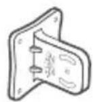
Protective Shroud

Pole-mount Clamps (Qty.2)

Bolts with Nut and Lock Washer Assemblies (M8×85, Qty.4)

Flat Washers (φ6, Qty.4)
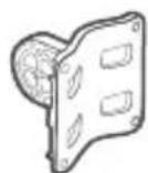
Adjustable Pole-mount BracketAntenna Mount

Installation Guide

RF Cables (Qty.2)
Bolts with Nut and Lock Washer Assemblies (M6×35, Qty.2)

Installation Requirements
• Outdoor Wireless Base Station (sold separately)
- Wrenches
Hardware Overview

Back View

Assembled Side View
Hardware Installation
- Attach the RF Cables to the Base Station.

natural_image
Diagram of a TP-LPV device with two speakers and two connected cables (no text or symbols)- Attach the Base Station to the Base Station Mount Bracket as follows: a. Align the mounting tabs on the back of the Base Station with the four mounting slots on the Base Station Mount Bracket. b. Slide the Base Station down until it locks into place.

- Connect the other ends of the RF Cables to the RF Connectors on the antenna.

- Slide the Protective Shroud down over the Base Station until it locks onto the Base Station Mount Bracket.

- Attach the Antenna Mount Bracket to the four studs located on the antenna using the Flat Washers, Spring Washers, and Hex Nuts.

natural_image
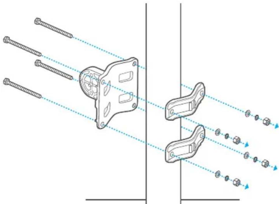
Technical diagram of a mechanical component with threaded fasteners and a housing, showing alignment lines (no text or symbols)- Attach the Adjustable Pole-mount Bracket and Pole-mount Clamps to the pole using four M8x85 Bolts with Nut and Lock Washer Assemblies.
Note: Pole diameter ranges from 40mm to 80mm.
natural_image
Technical diagram of mechanical components with alignment lines, no text or symbols present- Mount the Antenna Mount Bracket to the Adjustable Pole-mount Bracket using two M6x35 Bolts with Nut and Lock Washer Assemblies.
Note: Do not over-tighten these bolts and nuts to allow angle adjustment later.

natural_image
Technical line drawing of mechanical clamping components with alignment arrows (no text or symbols)- Adjust the desired elevation angle of the antenna using the scale marked on the Antenna Mount Bracket, and then tighten the bolt and nut assemblies.

natural_image
Technical line drawing of a mechanical device with a magnified inset showing angular measurement (no text or symbols)COPYRIGHT & TRADEMARKS
Specifications are subject to change without notice.
TP-LINK® is a registered trademark of TP-LINK TECHNOLOGIES CO., LTD. Other brands and product names are trademarks or registered trademarks of their respective holders. No part of the specifications may be reproduced in any form or by any means or used to make any derivative such as translation, transformation, or adaptation without permission from TP-LINK TECHNOLOGIES CO., LTD. Copyright © 2015 TP-LINK TECHNOLOGIES CO., LTD. All rights reserved.
Website: http://www.tp-link.com
Tel: +86 755 26504400
E-mail: support@tp-link.com


Brand : TP-LINK
Model : TL-ANT2415MS
Category : TV Antenna