
Neutrino - Uncategorized FLIR - Free user manual and instructions
Find the device manual for free Neutrino FLIR in PDF.


| Product Type | Thermal Camera Core |
| Brand | FLIR |
| Model | Neutrino |
| Detector Type | Uncooled VOx Microbolometer |
| Resolution | 640 × 512 pixels |
| Pixel Pitch | 12 μm |
| Spectral Range | 8–14 μm (LWIR) |
| Frame Rate | Up to 60 Hz |
| Temperature Sensitivity (NETD) | < 50 mK |
| Digital Video Output | 14-bit, LVDS or parallel |
| Control Interface | I²C, SPI, or UART |
| Power Supply | 3.3 V DC, 1.5 W typical |
| Dimensions (without lens) | 45 mm × 45 mm × 60 mm |
| Weight | 95 g |
| Operating Temperature | -40°C to +85°C |
| Storage Temperature | -55°C to +95°C |
| Lens Mount | M34 × 0.5 thread (compatible with FLIR lenses) |
| Maintenance | Clean lens with optical-grade cloth; avoid moisture and dust |
| Safety | No laser emission; standard ESD precautions |
| Repairability | Not user-serviceable; refer to FLIR authorized service centers |
Frequently Asked Questions - Neutrino FLIR
User questions about Neutrino FLIR
0 question about this device. Answer the ones you know or ask your own.
Ask a new question about this device
Download the instructions for your Uncategorized in PDF format for free! Find your manual Neutrino - FLIR and take your electronic device back in hand. On this page are published all the documents necessary for the use of your device. Neutrino by FLIR.
USER MANUAL Neutrino FLIR
natural_image
Mechanical device with metallic and brass components, no visible text or symbols
FLIR Commercial Systems
6769 Hollister Ave
Goleta, CA 93117
www.flir.com
Document Number: 425-0025-00-10
Version: 120
Issue Date: Jun 14, 2018
The information herein does not contain technology as defined by the EAR, 15 CFR 772, is publicly available and therefore not subject to the EAR. NSR (6/14/2018)
425-0025-00-10 Rev120
Jun 2018
FLIR Systems, Inc.
Table of Contents
Neutrino .... 1
1.0 Document....5
1.1 Revision History ....5
1.2 Scope....5
2.0 Unpacking the Camera....5
3.0 Basic Accessories....6
3.1 VPC Module Accessory....7
3.2 Camera Link Module Accessory....8
4.0 Connecting to the Camera....8
4.1 FLIR Camera Controller GUI 8
4.2 Physical Connection....9
4.3 Software Connection....10
4.4 Digital Data via Camera Link....13
4.5 Troubleshooting the FLIR Camera Controller GUI....16
5.0 Operation of the FLIR Camera Controller GUI....16
5.1 Menu Bar 17
5.2 Status Tab....19
5.3 Setup Tab 19
5.3.1 External Synchronization of the Camera 20
Operating Mode 22
Save Settings....22
Factory Defaults....22
Reset Camera 23
Test-Pattern 23
5.4 Video Tab....24
Image-Orientation Mode....24
Zoom....25
E-Zoom 25
Pan and Tilt....25
Fine 25
Center....25
Video On/Off 26
Video Standard....26
Polarity/Palette....26
5.4.1 Digital Video Tab 28
Camera Type....28
Camera Digital Output....29
XP Bus Output....29
5.4.2 Image Capture Tab....30
Max Number of Snapshots....30
5.5 AGC Tab....35
AGC Modes 36
Linear Parameters ....38
Automatic Parameters....39
Dynamic Digital Detail Enhancement (DDE) filter 39
5.5.1 AGC ROI Tab 40
Window Editor....41
Entire Array ROI....41
AGC ROI Coordinate Values 41
5.6 Cooled Tab....43
5.6.1 Lens Control Tab 45
5.7 Advanced Tab 47
Digital Detail Enhancement (DDE) Data....48
Dynamic DDE Control....48
Splash Screen....48
Camera Configuration....48
5.7.1 Bad Pixel Elimination Tab....49
TABLE OF FIGURES
Figure 1: VPC Module Accessory Kit....7
Figure 2: Camera Link Module (shown on a Tau camera)....8
Figure 3: BNC to RCA Adapter ......9
Figure 4: VPC Physical Connections (shown on a Tau camera)....9
Figure 5: Device Manager showing proper driver installation ....10
Figure 6: FLIR Camera Controller GUI Status Tab – Not Connected....11
Figure 7: FLIR Camera Controller GUI Connection Window Part 1....12
Figure 8: FLIR Camera Controller GUI Connection Window Part 2....12
Figure 9: FLIR Camera Controller GUI Status Tab – Connected ....13
Figure 10: FLIR Camera Controller GUI – Digital VideoTab ....14
Figure 11: Imperx FrameLink Express Software – Camera Parameters Window....15
Figure 12: FLIR Camera Controller Error Message....16
Figure 13: FLIR Camera Controller GUI – Menu Bar ....17
Figure 14: Help -- About Camera Controller....18
Figure 15: FLIR Camera Controller GUI – Status Tab ....19
Figure 16: FLIR Camera Controller GUI -- Setup Tab ....20
Figure 17: AIWR Mode Synchronization....21
Figure 18: ATFR Mode Synchronization....22
Figure 19: Ramp test pattern example for Top Portion of Ramp Image....23
Figure 20: FLIR Camera Controller GUI -- Video Tab....24
Figure 21: Look-Up Table Options ......27
Figure 22: FLIR Camera Controller GUI – Digital Video Tab ....28
Figure 23: FLIR Camera Controller GUI – Image Capture Tab....30
Figure 24: 8-bit Snapshot Management....31
Figure 25: Multiple Bitmap Viewer windows ....32
Figure 26: Snapshot Viewer ....33
Figure 27: Snapshot Viewer with digital data....34
Figure 28: FLIR Camera Controller GUI -- AGC Tab 35
Figure 29: FLIR Camera Controller GUI – AGC ROI Tab....40
Figure 30: AGC ROI Example 41
Figure 31: FLIR Camera Controller GUI – Cooled Tab....43
Figure 32: FLIR Camera Controller GUI – Advanced Tab....47
Figure 33: FLIR Camera Controller GUI – Bad Pixel Elimination Tab....49
1.0 Document
1.1 Revision History
| Version | Date | Comments |
| 100 | 3/12/2014 | Initial Release corresponding with GUI version 1.0.0.109 |
| 120 | June/14/2018 | Changed title page to reflect EAR status |
1.2 Scope
The Neutrino version of the FLIR Camera Controller GUI is export controlled software that is used to configure and control the Neutrino camera. This User's Guide includes Quick Start information for the Neutrino as well as detailed descriptions of functions and adjustments for the camera that can be performed using the FLIR Camera Controller GUI for Neutrino.
2.0 Unpacking the Camera
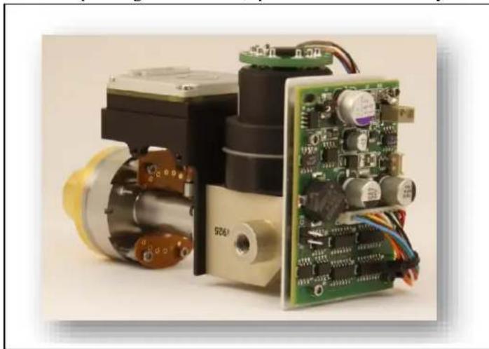
When unpacking the camera, please heed customary electrostatic-discharge (ESD) sensitive device
natural_image
Close-up of an electronic device with exposed circuit board and mechanical components (no visible text or symbols)precautions including static-safe work station and proper grounding. The camera is placed in a conductive anti-static bag to protect from electrostatic-discharge damage and safely packaged to prevent damage during shipping.
natural_image
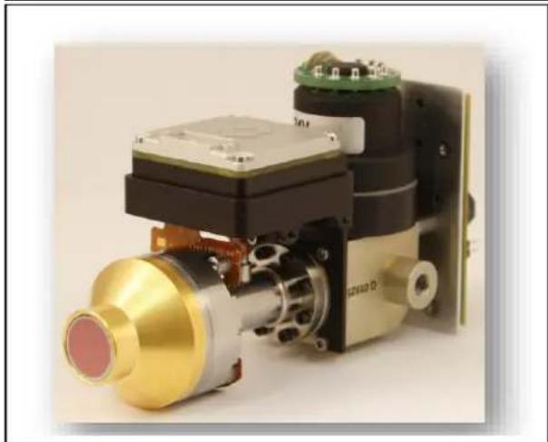
Close-up of a mechanical device with a golden cylindrical component and circuit board (no visible text or symbols)Disassembling the camera, for example to place the PCBA's in other places in a gimbal due to space constraints, is possible, but should not be done without assistance from FLIR because it could cause permanent damage and void the warranty. Operating the camera outside of the specified input voltage range or the specified operating temperature range can cause permanent damage. Avoid exposure to dust and moisture. The camera contains electrostatic-discharge-sensitive electronics and should be handled appropriately.
3.0 Basic Accessories
The Neutrino Camera can be used with either the VPC Module Accessory (FLIR PN 421-0039-00) or the Camera Link Module Accessory (FLIR PN 421-0046-00) for simple desktop purposes. These accessories provide an easy way to evaluate the camera core and access analog and, in the case of the Camera Link Module, digital video during development. These accessories can be found at http://www.flirshop.com.
3.1 VPC Module Accessory
The VPC module accessory includes USB-A to USB-mini B cable for power and communications, USB power supply, European power adapter, MCX-to-BNC cable for analog video, and mounting screws.
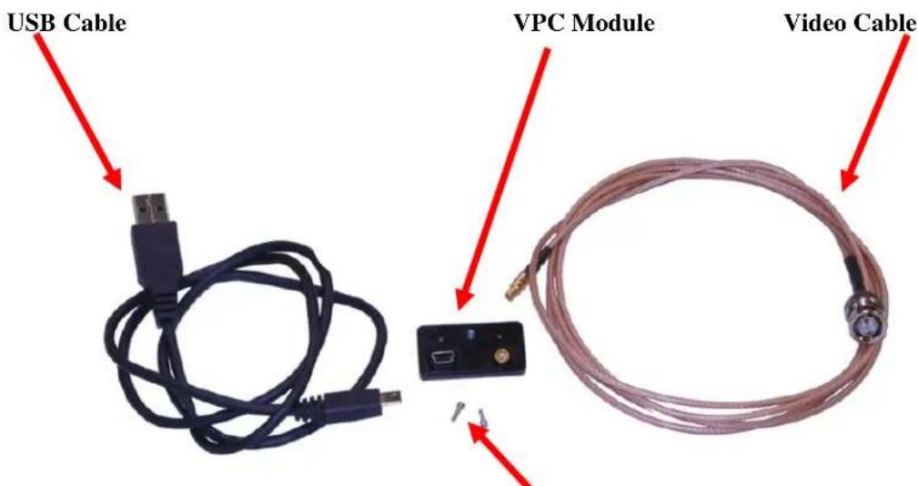
Figure 1: VPC Module Accessory Kit
Socket head cap screws (M1.6 × 0.35 × 6 mm)
(USB Power Supply and European Power adapter not pictured)
3.2 Camera Link Module Accessory
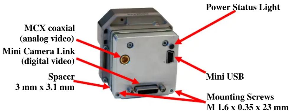
The Camera Link module is an expansion board for FLIR cameras that matches the functionality of the VPC Module and adds the ability to access digital data via Camera Link connection. The Camera Link module takes CMOS-type digital data from the camera and converts it to Camera Link. In order to use a Camera Link module for acquisition of data, first enable the CMOS XP Bus Output using the FLIR Camera Controller GUI (see Section 5.4.1). This accessory does not include a Camera Link cable, frame grabber, or capture software.
Figure 2: Camera Link Module (shown on a Tau camera)
4.0 Connecting to the Camera
This section describes installation of necessary software, physical camera connections, and software connection to the camera.
4.1 FLIR Camera Controller GUI
The FLIR Camera Controller GUI provides communication between a PC and a FLIR camera using either the USB interface or some other means of serial communication through the camera's connector.
- Computers with an older version of the FLIR Camera Controller GUI should first uninstall it using the Windows Uninstall utility via the Windows Control Panel before proceeding with this installation.
- The box in which the camera is delivered will contain a CD with a copy of the install file for the Neutrino version of the FLIR Camera Controller GUI described in this manual. Copy this file to a folder on the host computer.
- Open the directory where the saved file is and double-click "CameraControllerSetup.msi".
- Walk through the installation steps.
- When the primary installation is completed, a message will prompt to install Silicon Laboratories drivers. This portion of the installation is necessary for using a USB connection to the camera. There will also be a prompt to install Ethernet drivers but that is not necessary at this time as the camera does not presently support Ethernet options.
- The program will install to All Programs→FLIR Systems→Camera Controller GUI
4.2 Physical Connection
This section describes physical connections to the camera and assumes that either the VPC or Camera Link Accessory Module is being used with the camera.
-
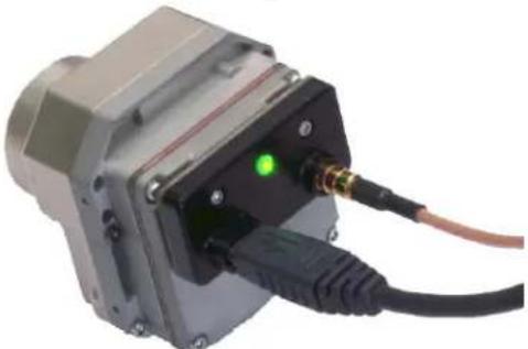
Plug the accessory directly into the top of the camera. There is a white 50-pin connector that will mate. Use the included socket head cap screws to secure the expansion board to the camera. These will insert on either side of the 50-pin connector. The VPC module uses M1.6 × 0.35 × 6 mm screws and the Camera Link module uses M1.6 × 0.35 × 24 mm screws. Using longer screws could damage the camera. An M1.5 allen head wrench will be required for tightening the screws.
-
Connect the analog video cable to the VPC or Camera Link Module on the back of the Tau Camera. There is an MCX mini coaxial connector on the back of the accessories. The opposite end of the cable has a standard coaxial connector. Connect this to the video input of an analog monitor. It may be necessary to use a BNC Female to Phono Plug (RCA) Adapter. These are readily available at electronics stores and allow the camera to be connected to the standard yellow video input on a monitor.
Note: For best transmission of the analog video channel, a coaxial cable with 75 ohm characteristic impedance is required. The analog output is current mode and a 75 Ohm termination is required. This termination is present in most display devices.
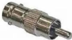
Figure 3: BNC to RCA Adapter
- Connect the USB-mini B cable to the VPC Module or the Camera Link Module and the USB-A end to the computer. (If sound is enabled on the computer, a chime will sound and a notification that the device has been connected will pop up).
natural_image
Close-up of a mechanical device with a green laser indicator and black cable, no visible text or symbolsFigure 4: VPC Physical Connections (shown on a Tau camera)
- Analog video (a Splash Screen) should appear within a few seconds after connecting the USB cable. Verify analog video is displayed on the monitor to ensure the camera electronics are properly powered. Some notebook computer USB ports provide just the minimum 500 mA (2.5W) and very
little headroom for turn-on current surge. The Neutrino camera may not function optimally under this condition.
-
There are two additional unterminated wires coming from the cooler controller PCBA on the back of the camera. These wires need to be connected to a 9 to 24 Volt power supply to power the cooler. The black wire is ground, the other wire is power. When this power supply is turned on, the cooler will start making an audible sound and begin to cool the Focal Plane Array (FPA). The progress of the cooldown can be monitored on the Status Tab of the GUI by monitoring the FPA temperature as shown in Section 5.2. When the FPA temperature reaches approximately 85 ~K , the splash screen will go away and be replaced by the image of the scene presented. When the temperature reaches about 77 ~K , the cooler will throttle back, the sound will be less audible, and the camera is ready for imaging. The camera will require about 10 Watts from the power source during the cooldown phase, and there will be a short spike of about 2 Amps on start-up.
-
Additional Information: Access the Device Manager to verify proper driver installation and identify the communications port. Connection issues are most often caused by attempting to use the wrong COM Port to connect to the camera.
a. Right-Click on "My Computer" and select "Manage". This is typically either on the desktop or available through the start menu.
b. Select "Device Manager" on the left Pane.
c. Expand the tree for "Ports (COM & LPT)".
d. Note the COM Port number used for Silicon Labs. The following example shows COM3.
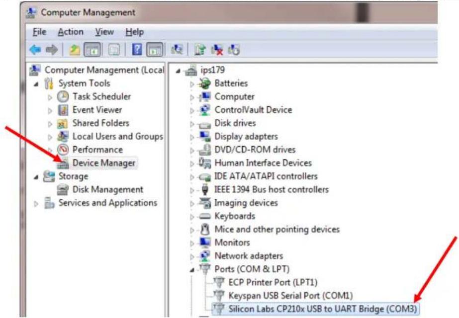
Figure 5: Device Manager showing proper driver installation
4.3 Software Connection
This section describes simple communication with the camera using the FLIR Camera Controller GUI and assumes that the camera is connected to the PC using a USB cable and either the VPC or Camera Link Accessory Module.
-
Run the FLIR Camera Controller GUI by clicking on the start menu and accessing Start→All Programs→FLIR Systems→Camera Controller GUI. (The software may take up to 30 seconds to load the first time.)
-
When the GUI first opens, it will display "Not Connected" on the bottom left. The first step is to connect to the camera.
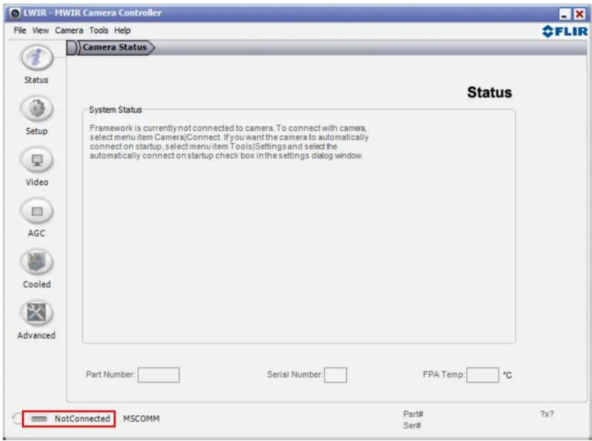
Figure 6: FLIR Camera Controller GUI Status Tab – Not Connected
- Connect to the camera by selecting Tools→Connection
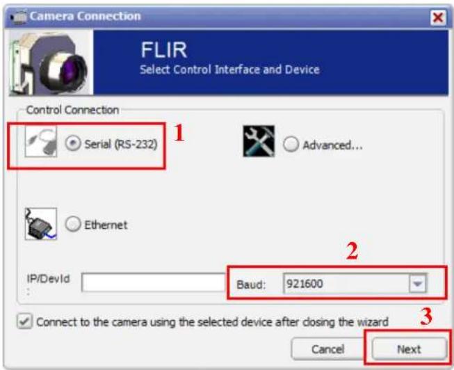
Figure 7: FLIR Camera Controller GUI Connection Window Part 1
- Select Serial (RS-232), select 921600 as the Baud Rate for fastest communication, and click Next. If there is only one serial communication port on the computer, the button will say Finish.
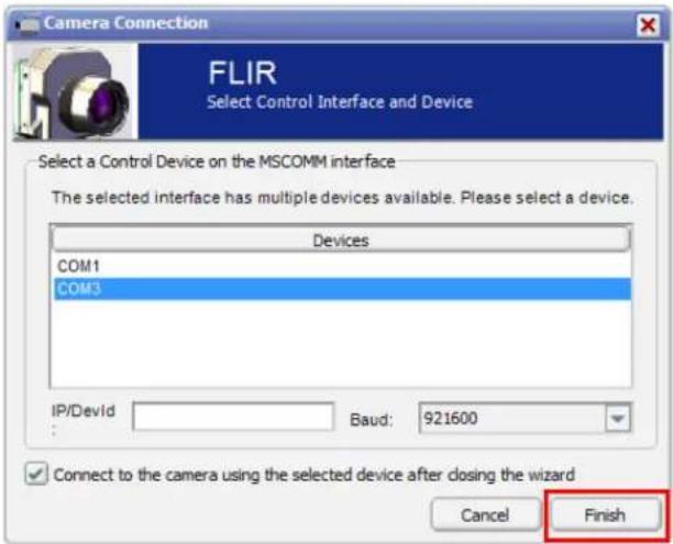
Figure 8: FLIR Camera Controller GUI Connection Window Part 2
-
Select the Com port seen in the Device Manager and click Finish. The first time the camera is connected a window will pop up asking the user to select the camera type. Select LWIR-MWIR.
-
The GUI will now automatically connect to the camera and refresh information in the software. The software will automatically identify the camera type and display "Neutrino Camera Controller" in the upper left of the Status screen. The status LED will turn green and it will display "Connected" on the bottom left. It is also possible to retrieve the part number and serial number of the camera from this screen.

Figure 9: FLIR Camera Controller GUI Status Tab – Connected
4.4 Digital Data via Camera Link
This section describes digital data acquisition with the Camera Link accessory and assumes that all prior sections have been successfully completed
-
Connect one end of the Camera Link cable to the camera. The camera connection is a Mini-Camera Link connector and frame grabbers may use either standard or Mini-Camera Link. It is possible to purchase cables that have mini connectors on both ends or standard on one end with mini on the other.
-
The camera must be configured to output CMOS digital data in order for the Camera Link accessory to work. This can be done by clicking "Video" on the left pane of the GUI, "Digital Video" tab on the top, and selecting "CMOS" for the XP Bus Output. Select either 14-bit or 8-bit, depending upon preference. 8-bit data has the AGC applied and looks similar to the analog video image. 14-bit data does not have AGC applied. See below for details on the format of the 14-bit data.
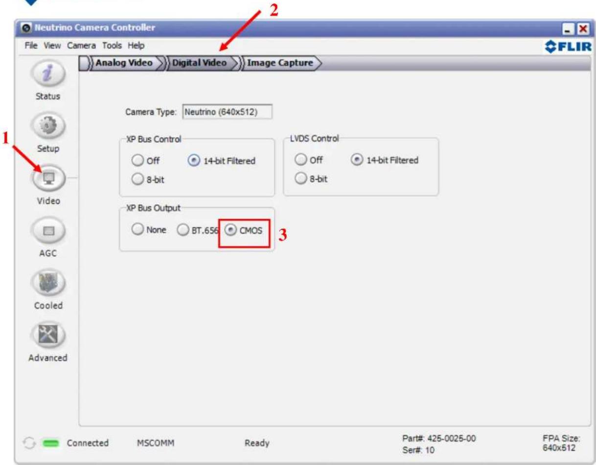
Figure 10: FLIR Camera Controller GUI – Digital Video Tab
- Once these changes are made, it is a good idea to save settings to make them power cycle persistent. This can be done on the Setup Tab by clicking the "Save Settings" button.
- The digital data complies with Base Camera Link standards and will be compatible with most off-the-shelf Camera Link frame grabbers. FLIR has tested the ImperX FrameLink Express frame grabber (http://imperx.com/frame-grabbers/framelink-express) and the Matrox Solios Camera Link frame grabber.
(http://www.matrox.com/imaging/en/products/frame_grabbers/solios/solios_ecl_xcl_b/). It is important to note that this module provides access to digital data only and the other portions of the Base Camera Link specifications are not met. Camera control, external frame sync, and power through the Camera Link connector are not supported.
- If a BitFlow framegrabber is to be used, consult FLIR for the necessary hardware.
- The FLIR Camera Controller GUI allows for control of the FLIR camera, but does not support Camera Link frame capture and so third-party software must be used. The ImperX frame grabber includes FrameLink Express software that allows for recording single or multiple images (BMP, JPG, TIF, and RAW) as well as standard AVI clips. Configuration requires selecting:
“1 TAP, L->R” for the tap reconstruction, selecting the same bit depth that was chosen in the FLIR Camera Controller GUI in step 2, and clicking “Learn” to discover the number of digital pixels available.
7. Click Apply and Start Grab
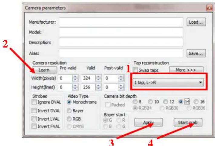
Figure 11: Imperx FrameLink Express Software – Camera Parameters Window
- Note: If the image appears to have very little contrast, the output is likely in 14-bit mode. If that is the intended setting, use the histogram feature in the frame-grabber software to change the display range. Otherwise, set the camera to 8-bit Digital Output Mode and the frame-grabber to 8-bit capture mode. Click “Apply” in the frame grabber software. The camera will now use its built in AGC functionality that is accessible from the AGC tab in the FLIR Camera Controller GUI.
4.5 Troubleshooting the FLIR Camera Controller GUI
If the FLIR Camera Controller GUI does not link with the camera, there will be a popup shown below which indicates that the GUI has not been able to communicate with the camera.
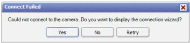
Figure 12: FLIR Camera Controller Error Message
If this is the case, verify the following:
- The USB Cable is properly connected to both the computer and the Accessory Module so that there is a green LED illuminated on the accessory.
- Verify the proper port was selected if it was not detected automatically. Select Advanced, then Next in the Tools→Connection dialog box. Also, try disconnecting and then re-connecting the cable to the PC. If the GUI was launched before the cable was connected, close the GUI, connect the cable, and then re-launch the GUI.
- The Baud rate must be set in the Tools→Connection dialog box. The FLIR camera supports Baud rates of 57600 and 921600. The FLIR camera automatically detects if the Baud Rate of the first incoming message is either 57600 or 921600 and will communicate at that Baud Rate until reset.
- The Port may be occupied by another application. Shut down any other applications that may be using the port. Also, multiple instances of the FLIR Camera Controller GUI Program can be instantiated using different ports so be sure the camera that is interested in being controlled is actually connected to the physical port that was verified in the Device Manager in Section 4.2, step 6.
- Verify that the camera is powered by checking that the camera is producing an image on an analog monitor. The Neutrino camera takes approximately seven minutes to start up, cool down the focal plane array (FPA) to its operating temperature and provide video. Until this time a splash screen will be displayed on the monitor. Digital video will not be available until the FPA is cold.
- If the GUI says SWIR Camera Controller on the top, try to use Camera→Select to select LWIRMWIR rather than SWIR. If this option is not present, the GUI will need to uninstall using the Windows Uninstall utility via the Windows Control Panel and delete the Program Files directory (C:\Program Files (x86)\FLIR Systems\Camera Controller GUI). The latest .NET Framework will also need to download and installed from Microsoft (http://www.microsoft.com/net/download). It is best to use the client profile from the web. Once this is updated, install the Camera Controller GUI and use Camera→Select to select LWIR-MWIR rather than SWIR.
If serial communication cannot be initiated with the camera after verifying these items, refer to the frequently asked questions (FAQ) at http://www.flir.com/cvs/cores/faqs/tau/all/. Additionally, a FLIR Applications Engineer can be contacted at 888.747.FLIR (888.747.3547).
5.0 Operation of the FLIR Camera Controller GUI
This section describes operation of the FLIR Camera Controller GUI and explains adjustments that can be made to the camera.
5.1 Menu Bar
The FLIR Camera Controller GUI has a classic menu bar where drop down menus are displayed.

Figure 13: FLIR Camera Controller GUI - Menu Bar
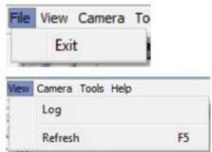
File: The file menu has the option to Exit. This will close the GUI and can also be performed by clicking the x on the top right corner.
View: Select Log to display a log at the bottom of the GUI. This does not display all commands sent to the camera, but rather displays connection information and possible error messages. This Logger pane is displayed in some of the screen shots below.
Click Refresh to refresh the GUI. This can also be done with the F5 function key on a keyboard.
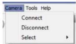
Camera: Select Connect to connect to a camera using the same communications parameters that were used previously. If connection cannot be established, it will ask to retry or open the connection wizard. Select Disconnect to open the COM port that the GUI is occupying and disconnect from the camera. This can be useful if using other software to communicate with the camera.
The Select submenu allows selection of different camera types. The type "LWIR-MWIR" can be used for Neutrino, Quark, Tau 2, Tau, and Photon.
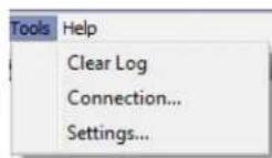
Tools: Select Clear Log to clear the log that can be displayed using the View menu.
Select Connection to open the connection wizard. This allows the ability to configure communication settings such as COM Port and baud rate. Select Settings to configure the GUI. It is possible to configure the GUI to automatically connect at startup using the previous settings, allow multiple instances to be open at once, or change communication timing parameters.
Help: Open the Camera Controller User Guide in the default pdf viewer. The latest version of this document installs in the Program Files directory.
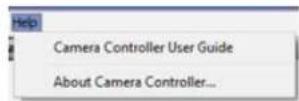
Select About Camera Controller to open a separate window with version information for the GUI and the camera.
About: The GUI Framework is the version of the GUI. The Main App is the software version of the camera. The version in the example is 17.0.2.179. The firmware is 16.1.1.36.
Click Details to view versions for each individual dll in the GUI.
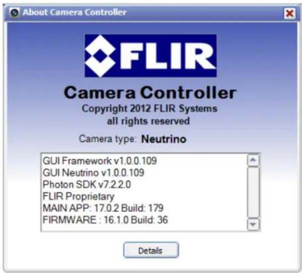
Figure 14: Help -- About Camera Controller
5.2 Status Tab
When the FLIR Camera Controller GUI successfully links to the camera, the window shown below will be visible. At the bottom of the application window, there is the Camera and FPA status. The GUI provides six tabs allowing for camera control as described below.
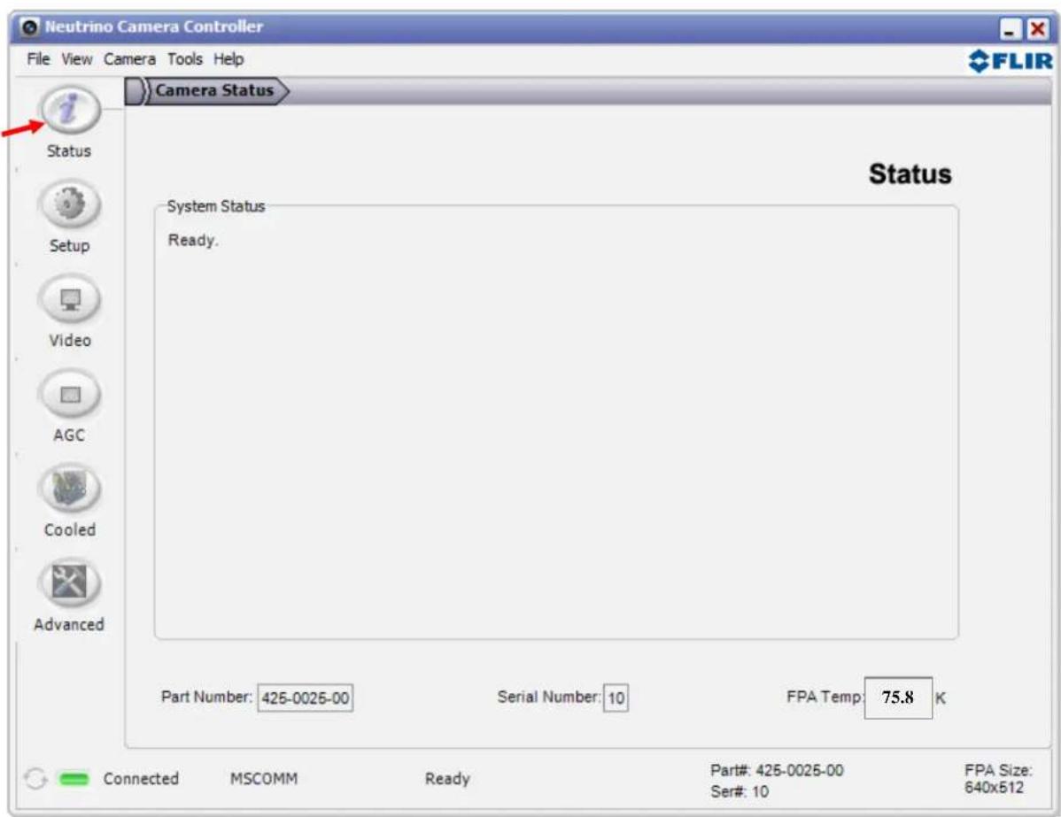
Figure 3: FLIR Camera Controller GUI – Status Tab
Camera Part #: This indicates the specific camera configuration connected. Please refer to the appropriate Product Specification for details understanding the part number.
Camera Serial #: This is the serial number of the camera currently connected to the FLIR Camera Controller GUI.
FPA Temperature: The camera's Focal Plane Array (FPA) temperature in Kelvins.
Note: The connection status, Camera status, Camera Part #, Serial # and FPA Size are displayed at the bottom of all tabs.
5.3 Setup Tab
The Setup tab, shown below, provides the ability to set and save basic settings in the camera. The camera can be operated in free run mode or can use an external synchronization method (Section 5.3.1). The camera also provides a frozen video mode and a test pattern ramp mode for trouble shooting purposes. If configuration options are changed in the camera the Save Settings button should be used before resetting the camera. Factory Defaults helps the customer return the camera to the options originally configured by the factory when shipped.
5.3.1 External Synchronization of the Camera
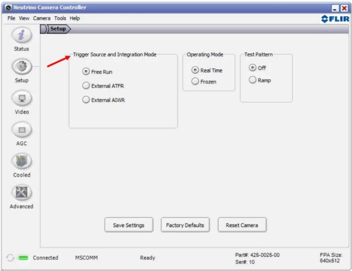
Figure 4: FLIR Camera Controller GUI -- Setup Tab
The Neutrino camera provides options for external synchronization and triggering (Figure 16). Options for the synchronized event (integration, data readout, video output) are discussed below. When an option other than Free Run is selected, a warning dialog will appear telling the user that an external synchronization source (3V to 3.3V square wave) must be connected before using the new external sync mode.
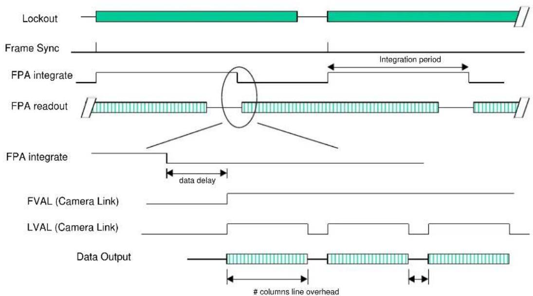
Asynchronous Integrate While Read (AIWR). Probably the most common synchronization task is to control the start of the FPA integration period with an external signal. The AIWR mode offers the most flexibility for accomplishing this.
Figure 17 illustrates the camera level timing of the AIWR mode. The externally provided frame sync controls the start of the integration period, which causes scene charge to be collected for the length of time that has been programmed by the user. At the end of the integration period, the FPA readout process begins. This is shown in the lower part of the figure which includes the Camera link frame and line valid signals.
The duration of the readout process is determined by the user selected window size – all pixels in this window must be read out. At a time that is approximately the selected integration time prior to the end of read out it is possible to start the next integration period (i.e. integrate while read). This is indicated in the figure by the end of the lockout period; at that point the camera will accept another frame sync input. As illustrated here, the user waits a short period before issuing the sync – at that time, the integration period and lockout period begin again. During the lockout period, the camera will ignore any external syncs.
flowchart
graph TD
    A["Lockout"] --> B["Frame Sync"]
    B --> C["FPA integrate"]
    C --> D["FPA readout"]
    D --> E["FPA integrate"]
    E --> F["FVAL (Camera Link)"]
    E --> G["LVAL (Camera Link)"]
    E --> H["Data Output"]
    style A fill:#99ccff,stroke:#333
    style B fill:#99ccff,stroke:#333
    style C fill:#e6f2ff,stroke:#333
    style D fill:#e6f2ff,stroke:#333
    style E fill:#e6f2ff,stroke:#333
    style F fill:#e6f2ff,stroke:#333
    style G fill:#e6f2ff,stroke:#333
    style H fill:#e6f2ff,stroke:#333
    note right of C "Integration period"
    note right of D "data delay"
    note right of F "# columns line overhead"
Figure 17: AIWR Mode Synchronization
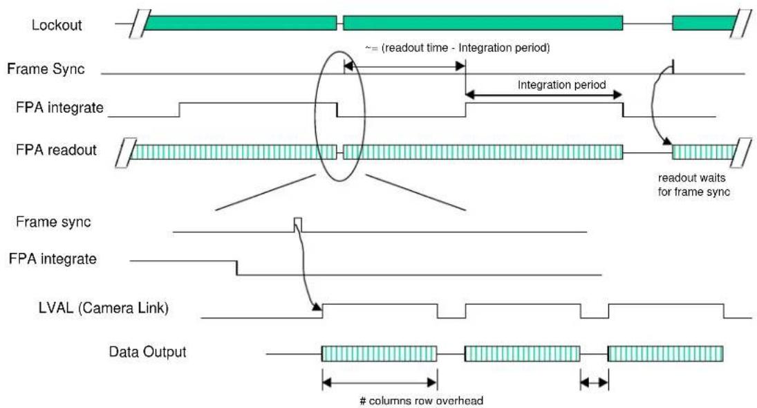
Asynchronous Triggered FPA Read (ATFR). The ATFR mode is used to synchronize the readout of scene information. This mode is useful for downstream signal processing elements that either need to control when data is sent or need a fixed relationship between the sync and when data is available.
Referring to Figure 18 below, the external frame sync initiates the readout period of the FPA. While not immediately apparent, it also initiates the start of the integration period at a time calculated by the camera which is approximately the time required for readout, less the user selected integration time.
At the end of the integration period, the FPA readout process is automatically started but the camera halts this immediately prior to the appearance of the first valid pixel. At this point, the lockout period ends and the camera will accept another sync. When the sync is received, the data readout process continues with
the readout of the first valid pixel, the lockout period begins, and at a later time, the integration period starts again.
flowchart
graph TD
    A["Lockout"] --> B["Frame Sync"]
    B --> C["FPA integrate"]
    C --> D["FPA readout"]
    D --> E["readout waits for frame sync"]
    E --> F["LVAL (Camera Link)"]
    F --> G["Data Output"]
    style A fill:#99ccff,stroke:#333
    style B fill:#99ccff,stroke:#333
    style C fill:#99ccff,stroke:#333
    style D fill:#99ccff,stroke:#333
    style E fill:#99ccff,stroke:#333
    style F fill:#99ccff,stroke:#333
    style G fill:#99ccff,stroke:#333
    note right of A: ~= (readout time - Integration period)
    note right of B: Integration period
    note right of C: Frame Sync
    note right of D: Frame Sync
    note right of E: FPA integrate
    note right of FPA readout
    note right of G: Data Output
    note right of FVA integrate
    note right of FVA sync
    note right of FVA data
    note right of LVAL
Figure 18: ATFR Mode Synchronization
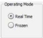
Operating Mode: The camera will freeze the analog frame imaged when Frozen is selected. Live video (both analog and digital) will cease and the frozen frame will persist in the analog video only. The Camera Link will stop outputting altogether. To return the camera to live video, select Real-Time video mode. "Frozen" cannot be saved as the power-on default state. Neutrino will always come up in the Real Time mode at power on.
Save Settings: After using the FLIR Camera Controller GUI to change Camera modes and settings to desired values, use the Save Settings button to store many of the current selections as new power-up defaults. The next time the camera is powered; the camera will remember these saved settings. If the Save Settings button is not clicked, any changes made via the FLIR Camera Controller GUI will be valid only for the current session. Cycling power to the camera will revert to the previously saved settings.
Note: The Save Settings button applies to changes made anywhere in the GUI, not only the Setup Tab.
Factory Defaults: The Factory Defaults button restores the camera's settings to the initial values specified by FLIR.
To save the factory default settings as the power up defaults, first click the Factory Defaults button, then click the Save Settings button.
Reset Camera: The Reset Camera button performs a soft reset that restarts the camera software.
Test-Pattern: A Test-Pattern mode is provided to adjust display properties and/or for diagnostic purposes (for example, to verify the core is providing a valid output). The Test-Pattern mode will not persist over a power cycle.
Off: No test-pattern is provided in this mode. This is the normal operation mode.
Ramp: In this mode, the test pattern shown below and in the Color/LUT section that follows is provided at the analog and digital data channels.
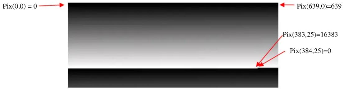
Figure 19: Ramp test pattern example for Top Portion of Ramp Image
(Digital values shown apply to the 14-bit digital data stream.)
The above ramp pattern repeats 19 times in the complete 640 × 512 image.
Note: The ramp test pattern is intended primarily for verifying the output of the digital data channel. The pattern will not necessarily look as shown above when displayed on an analog video monitor, particularly if an Automatic Gain Control (AGC) mode other than Automatic is selected. If a Color LUT has been selected on the Video Tab, the ramp will show the colors as described in that section below. The above image is a horizontal slice of the full displayed image. Three other ramp patterns are available in the Ramp pulldown which can also be used for troubleshooting.
5.4 Video Tab
The Video tab on the FLIR Camera Controller GUI, shown below, provides the ability to configure the camera's analog output.
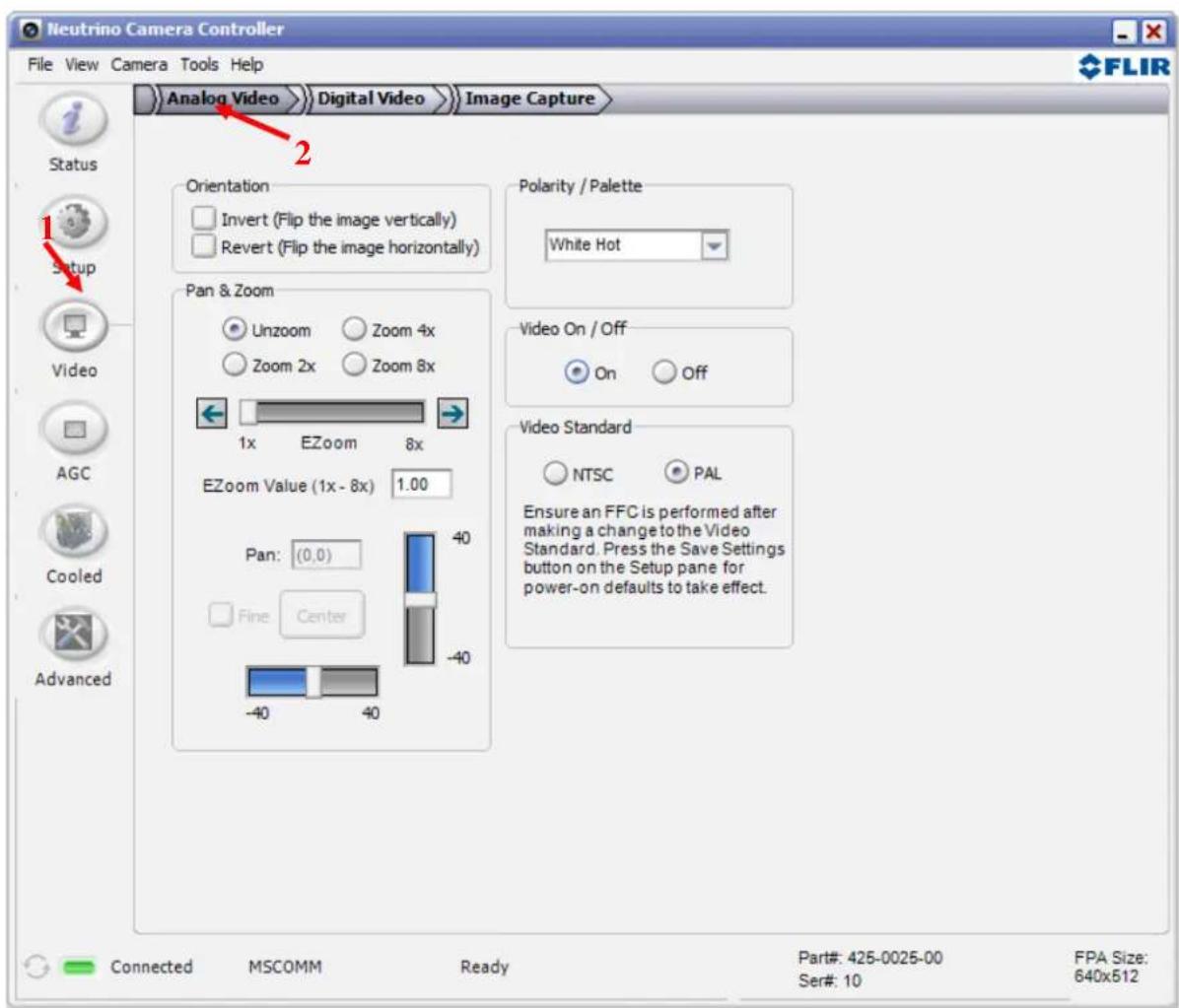
Figure 20: FLIR Camera Controller GUI -- Video Tab
Image-Orientation Mode: Two Image-Orientation mode selections are provided. Select one or both to change the orientation of the video image.
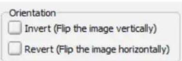
Invert: The normal image is flipped vertically. The pixel on the upper-left corner of the detector array is displayed on the lower-left corner of the video display in Invert mode. This is the
recommended mode when the core images the scene via a vertical fold mirror. Invert applies to all output channels (i.e., also CMOS, and LVDS).
Revert: The normal image is flipped horizontally. The pixel on the upper-right corner of the detector array is displayed on the upper-left corner of the video display. This is the recommended mode when the core images the scene via a horizontal fold mirror, when used in a rear-facing application intended to simulate the view through a rear-view mirror. Revert applies to all output channels (i.e., also CMOS, and LVDS).
Invert/Revert: Both should be selected if the camera is to be mounted upside down, or a lens is used which has a number of elements (e.g. 1 or 3) which themselves perform an inversion and reversion.
Note: Adjusting image orientation should always be followed by a 2-point calibration event (on the Cooled tab of GUI). A Flat Field Calibration (FFC) may be used to give a quick check to see if the desired orientation has been achieved, but that will not give the best image over scene temperature.
Zoom: The camera has built in discrete steps of digital zoom capability. For Neutrino with 640 x 512 resolution, it is possible to zoom to 8x. The camera always zooms to the center of the video.
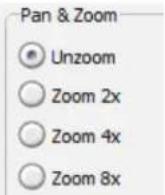
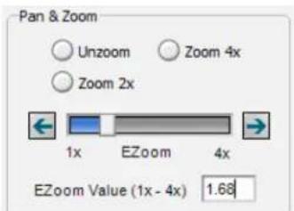
E-Zoom: The Neutrino camera provides the capability for continuous zoom. The user can adjust the zoom with the arrows or enter the desired zoom multiplier in the box provided. The maximum zoom is based on the resolution (8x for Neutrino).
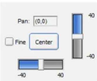
Pan and Tilt: The user may pan left or right and tilt up or down while zoomed. The zoom level is a function of the current analog output resolution and defaults to interpolating the center pixels described in the Zoom section above. The Pan and Tilt shifts this interpolated window by up to 40 pixels in any of the four directions: up, down, left, or right.
Fine: Enabling Fine will limit the Pan and Tilt to 20 pixels in all directions to provide a smaller step in pan/tilt on the order of a single pixel.
Center: Pressing the Center button will return the Pan and Tilt coordinates back to the center of the image.
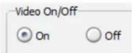
Video On/Off: This feature allows the ability to turn off the analog video output which will result in power savings (approximately 75mW).
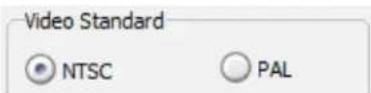
Video Standard: Choose the video standard for the system the camera will be used in. It is necessary to perform an FFC after changing the video standard. This can be done using the Do FFC button on the Setup Tab. To have the standard be the default at power up, click on the Save Settings button on the Settings Tab. Changing the video standard affects the operating frame rate of the camera in both the analog and digital output.
Polarity/Palette: The camera detects and images the temperatures in a given scene. Within the camera, these temperatures are mapped (as determined by the AGC algorithm selected) to a range of 0 to 255 values. In a black and white display mode, this range is converted to shades of gray with 0 being totally black and 255 being totally white.
The 0 to 255 grayshades range can also be referenced to a Look-Up Table (LUT) permanently stored in the camera to convert the scene to a color video image. Different LUTs are available to change the appearance of the displayed image. The most common selection is either White Hot (hotter objects appear brighter than cooler objects in the video display) or Black Hot (hotter objects appear darker than cooler objects). Since the difference between these two modes simply reverses the choice of darker or lighter for temperature extremes, this is sometimes referred to as Polarity. Other color LUTs are available as shown below.
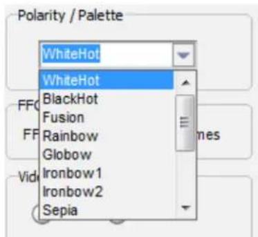
Figure 21: Look-Up Table Options shows each of the LUTs as displayed in Test Pattern Ramp Mode starting with the upper left: White Hot, Black Hot, Fusion, Rainbow, Glowbow, Ironbow1, Ironbow2, Sepia, Color1, Color2, Ice Fire, and Rain. Select one of these LUTs from the pull-down menu to view the image displayed using the chosen LUT. Setting the Polarity/LUT mode will not affect the CMOS or LVDS digital data output.
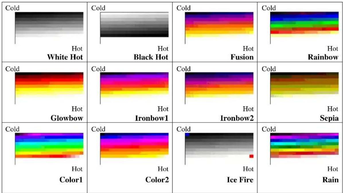
Figure 21: Look-Up Table Options
Simple experimentation with this feature while viewing the video image will provide familiarity. Remember to click the Save Settings button on the Setup Tab to save the LUT settings as the default at power-up.
5.4.1 Digital Video Tab
The camera offers digital output that can be configured in three modes. Changing these modes will have no effect on the analog (NTSC or PAL) signal. Refer to the appropriate Electrical IDD for information on how to access digital video for LVDS. CMOS digital data can be accessed using the Camera Link accessory described above.
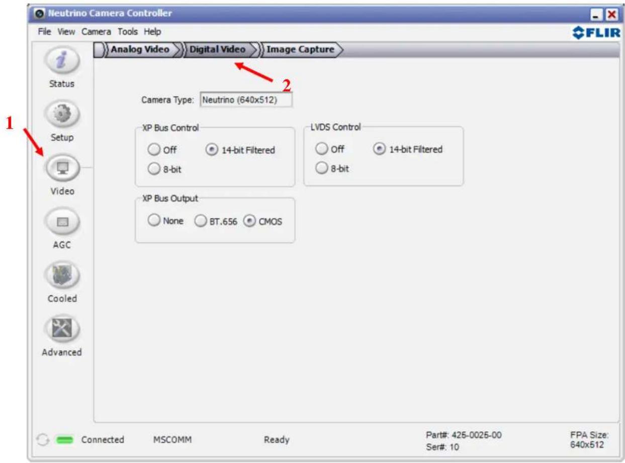
Figure 5: FLIR Camera Controller GUI – Digital Video Tab
Camera Type: This field displays the camera type that is currently connected to the GUI. The active array output displayed is the necessary setting for a frame-grabber.
Camera Digital Output: Select the desired digital data format. These settings will affect both the LVDS data and the XP Bus data. The XP bus hosts the CMOS data.
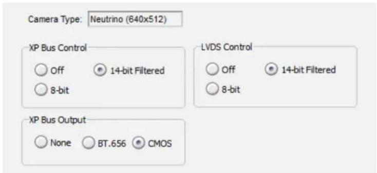
Off: The digital data stream coming from the camera is turned off.
8-bit: Data is provided after application of the current Automatic Gain Control (AGC) and Dynamic Detail Enhancement (DDE). The 8-bit data is essentially a digital version of the same data provided on the analog video channel, but LVDS and CMOS data does not include LUT or zoom.
14-bit Filtered: Data is provided prior to video processing modes in the 8-bit data described above. The 14-bit data is the filtered data to include the Dynamic Detail Enhancement (DDE) and bad pixel replacement. This data may appear to have very low contrast when saving 16-bit TIFF files; use post-processing to reduce the dynamic range.
Note: AGC will only affect the digital data output if Camera Digital Output Mode is set to 8-bit data.
XP Bus Output: The camera has a set of pins defined as eXPansion (XP) pins.
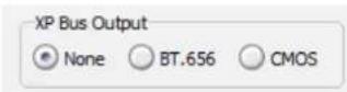
CMOS: The CMOS interface is a parallel output that allows the user to access 8-bit AGC corrected data or 14-bit data. Changing the data format in the Camera Digital Output section will affect the CMOS data.
Note: The XP Bus will not output any BT.656 data on the Neutrino camera.
5.4.2 Image Capture Tab
The Image Capture tab on the FLIR Camera Controller GUI allows the capture of images to camera memory for retrieval to a host computer over the serial port.
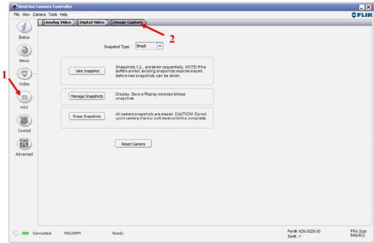
Figure 23: FLIR Camera Controller GUI – Image Capture Tab
Capturing Snapshots: Select the “Bmp8” or the “Comp14” option from the Snapshot Type dropdown menu to specify whether a 8-bit snapshot of 14-bit snapshot is desired. To capture a snapshot select the
“Take Snapshot” button: . This button captures a snapshot of the specified type and saves it in the next available slot in memory. When memory is full and the “Take Snapshot” button is selected, an error will be reported to indicate that the memory must be erased before it is possible to continue capturing snapshots.
Max Number of Snapshots: There are approximately 20 8-bit snapshots for a 640 resolution FLIR camera. Note: The 14-bit and 8-bit snapshots occupy the same memory location, and the above values for approximate number of 8-bit snapshots assume there are no 14-bit snapshots also stored. If the user commands a snapshot while simultaneously recording the first, the second capture command will be ignored and only the initial snapshot will be saved.
Erase Snapshots: Snapshots will stay in the camera until erased. This button will erase all the snapshots from the camera, allowing new snapshots to be taken. This function will take some time and the GUI will update the status when complete. Do not disconnect power or reset the camera while erasing memory.
Note: Erase Snapshots will erase both 8-bit and 14-bit snapshots simultaneously. Ensure that any desired snapshots are saved before erasing all snapshots with this button.
Bmp8 Snapshots: On the "Image Capture" tab, specify the Snapshot Type specified as "Bmp8" in the drop-down menu. The

Manage Snapshots
button appears to display the snapshots previously captured in memory and offer options for playback, viewing, and saving. Once selecting the “Manage Snapshots” button, the Image Selector window will appear displaying the snapshots sequentially. Note that a snapshot must be selected (highlighted) to enable the buttons at the bottom of the pop-up window which allow saving, viewing, and playing back the stored snapshots. For convenience, once in the Image Selector window, the snapshots can be selected with either a mouse-click or the user’s arrow keys.
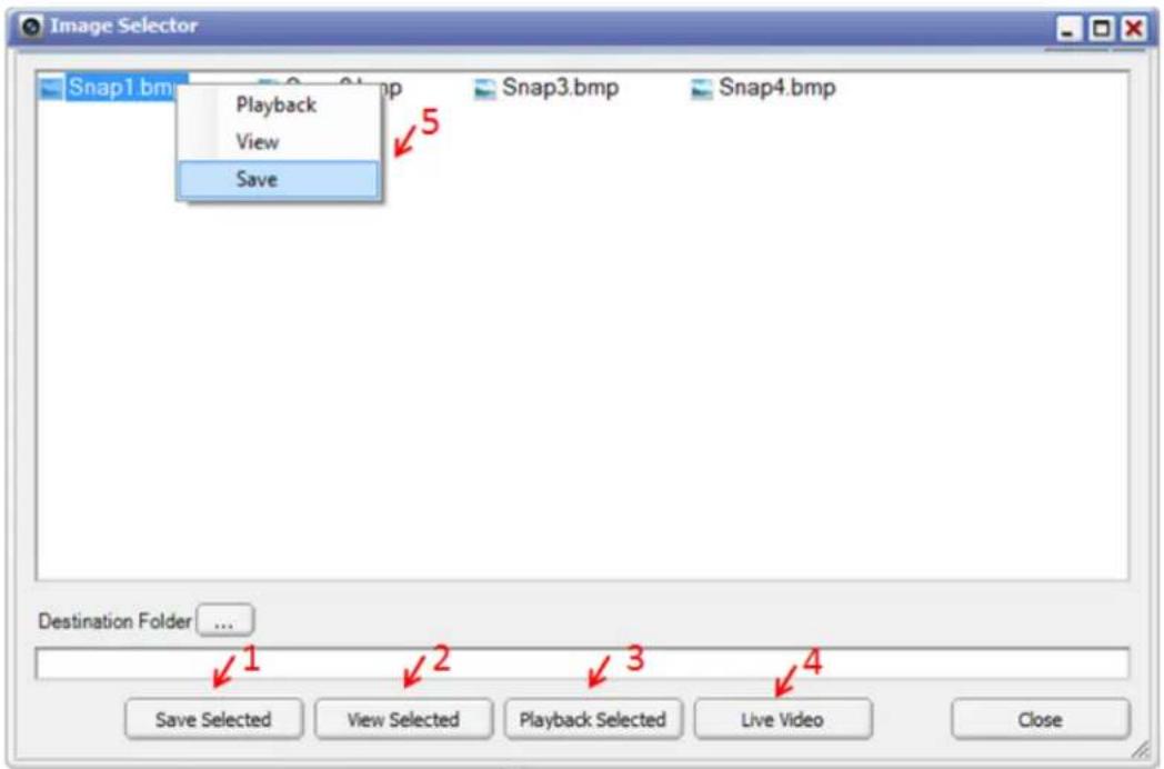
Figure 64: 8-bit Snapshot Management
The snapshots can be uploaded and saved from the camera to the user's PC or network from the Image Selector window in multiple user-convenient manners. From the Image Selector window, select the desired snapshot. Type in the destination folder or browse to the desired location using the following button:
Destination Folder ...
. Once the destination has been selected and the desired snapshot has been highlighted the snapshot can be saved using the following methods:
- Select the snapshot and use the "Save Selected" button from the Image Selector window (Fig. 24 #1)
- Right-click on the snapshot in the Image Selector window and a select “Save” from the drop-down list (Fig. 24 #5)
- Drag and drop the selected snapshot from the Image Selector window into the desired location
A pop-up window with a progress bar will indicate the download status, and the window will disappear when the download is complete.
Similar to saving snapshots, there are multiple ways to view a snapshot from the Image Selector window. To view a snapshot, select the desired snapshot and use one of the following intuitive methods:
- Select the "View Selected" button in the Image Selector window (Fig. 24 #2)
- Right-click on the snapshot and select "View" from the drop-down list (Fig. 24 #5)
- Simply double-click on the snapshot
A progress bar will appear while the image is being retrieved, and then a separate Bitmap Viewer window will open displaying the selected snapshot. Note that the snapshot can be saved from the Bitmap Viewer window also, in addition to the ways previously mentioned.
Note: that multiple snapshots can be viewed simulataneously; each snapshot will appear in its own separate viewer window as shown below.
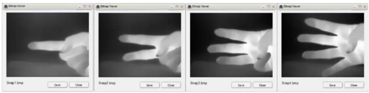
Figure 7: Multiple Bitmap Viewer windows
Playback: It is also possible to playback a specific snapshot on the analog video output of the camera. From the Image Selector window, select the desired snapshot and select the “Playback Selected” button (Fig. 24 #3). Right-clicking on the desired snapshot and selecting “Playback” from the drop-down list will also result in snapshot playback.
The desired snapshot will be displayed on the analog video for an unlimited amount of time. To return the analog video to live imaging, select the “Live Video” button (Fig. 24 #4) from the Image Selector window.
Comp14 Snapshots: For Snapshot Type specified as “Comp14” in the drop-down menu the “Retrieve Snapshot” button appears to provide viewing and saving capabilities. The Snapshot Number will begin with
Snapshot Type:
Comp14
one regardless of the number of 8-bit snapshots stored in memory before it – the numbering scheme only refers to the 14-bit snapshots stored in memory.
After selecting the “Retrieve Snapshot” button for the desired Snapshot Number, a progress bar will appear during loading, and finally the

Snapshot Viewer window will appear, as shown in figure 26. A cross-hair symbol is applied for the user's mouse location in the viewer window; the information bar at the bottom of the window displays the coordinates and digital value of the pixel currently pointed at (figure 26, #1). The minimum, maximum, and average pixel value with respect to the entire array are also displayed in the information bar.
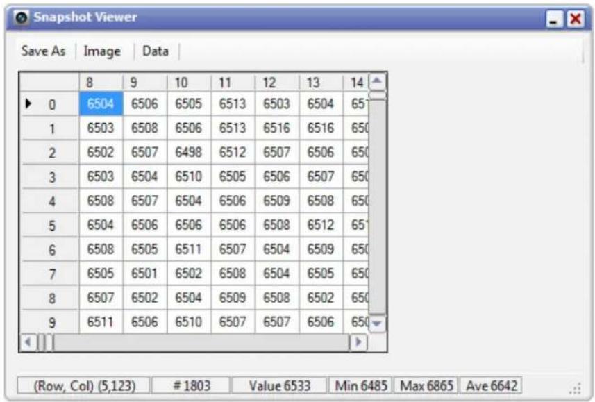
The options at the top of the window will allow the user to save the images via the “Save As” button (figure 26, #2) and view the per pixel 14-bit data via the “Data” button (figure 26, #3). Figure 24.b shows per pixel data versus x and y coordinates displayed in the Snapshot Viewer; the data may be copied and exported for external use.
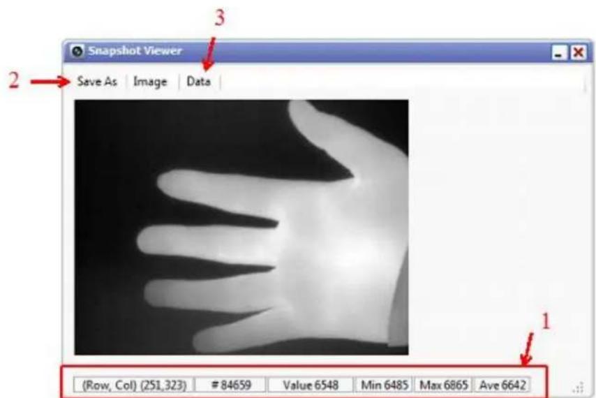
Figure 86: Snapshot Viewer
other
| Row | Col | Value | |---|---|---| | 0 | 6504 | 6506 | | 1 | 6503 | 6508 | | 2 | 6502 | 6507 | | 3 | 6503 | 6504 | | 4 | 6508 | 6507 | | 5 | 6504 | 6506 | | 6 | 6508 | 6505 | | 7 | 6505 | 6501 | | 8 | 6507 | 6502 | | 9 | 6511 | 6506 | | 10 | 6505 | 6511 | | 11 | 6513 | 6513 | | 12 | 6503 | 6516 | | 13 | 6504 | 6516 | | 14 | 6506 | 6507 | | 15 | 6508 | 6509 | | 16 | 6512 | 6508 | | 17 | 6504 | 6504 | | 18 | 6504 | 6508 | | 19 | 6502 | 6509 | | 20 | 6508 | 6507 | | 21 | 6506 | 6507 | (Row, Col) (5,123) #1803 Value 6533 Min 6485 Max 6865 Ave 6642Figure 27: Snapshot Viewer with digital data
5.5 AGC Tab
The AGC tab controls the Automatic Gain Control (AGC) modes and the enhancement algorithms. Parameters for a given mode are contextually made available depending on which mode is selected.
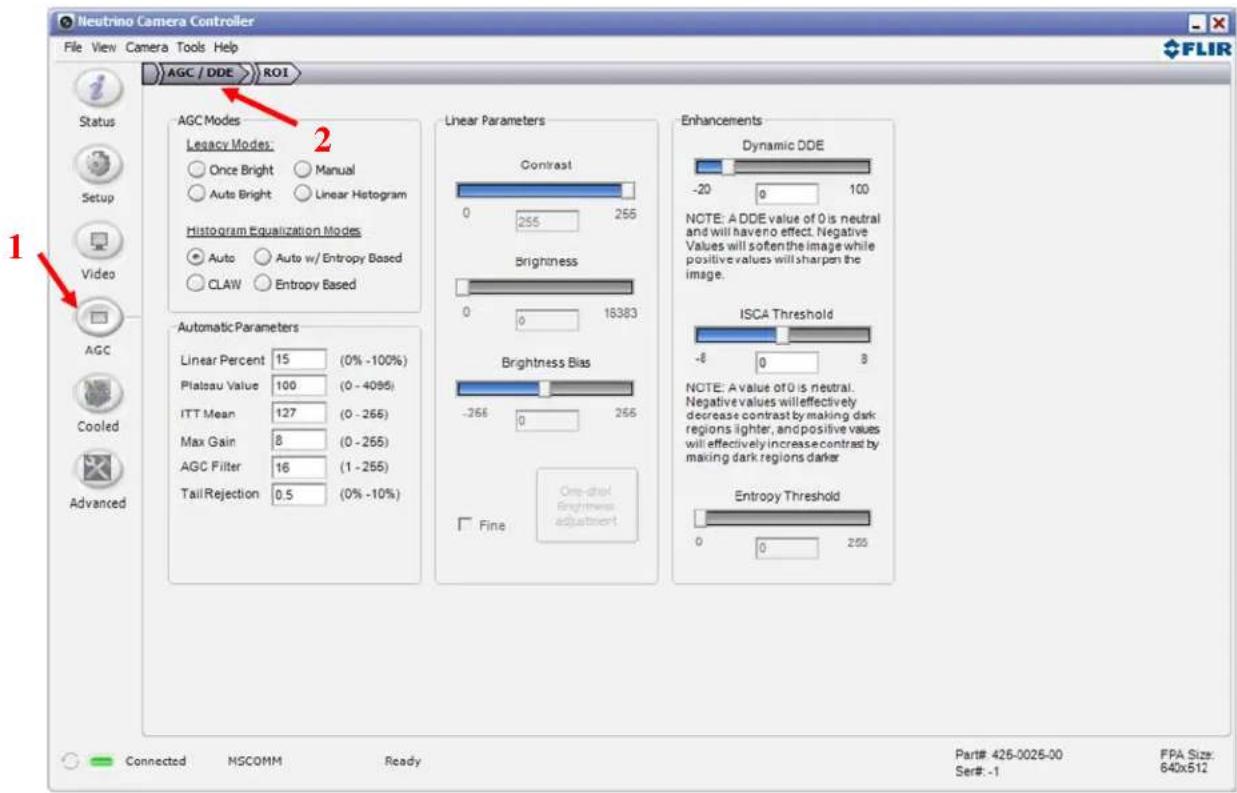
Figure 28: FLIR Camera Controller GUI -- AGC Tab
Note: The default mode (“Auto”) along with the default parameter settings for the Automatic AGC mode have been proven to offer the best image quality for generalized scene imaging. It may be possible to tune the AGC to achieve a better image for a given scenario. Also, be aware that it is possible to make AGC adjustments that will configure the camera to produce no 8-bit image (all black or all white). Restoring the Factory Defaults on the Setup Tab will return the camera to its factory default state.
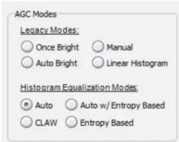
AGC Modes: There are four Histogram Equalization Modes included in the Neutrino camera. There are also four Legacy Modes for customers wishing to stay with existing AGC modes from previous revisions of FLIR cameras.
Histogram Equalization Modes:
Automatic (“Auto”): This is the most sophisticated algorithm and for most imaging situations, the best all-around choice. This factory default along with the default parameter settings should be used in general imaging situations. In Automatic, image contrast and brightness are optimized automatically as the scene varies. This mode provides an AGC which is based on a plateau histogram equalization algorithm. An excellent starting point for the understanding of histogram equalization can be found in Wikipedia at http://en.wikipedia.org/wiki/Histogram_equalization. The implementation in the Neutrino camera is much more sophisticated than the basic, providing controls for the Linear Percent (low “bin” enhancement), Plateau Value (histogram high “bin” clipping level), ITT Mean (gray scale midpoint), Max Gain (AGC gain), AGC filter (speed at which the AGC reacts), and Tail Rejection (removes outermost values of the histogram) with available ranges to the side of the configurable values. Adjusting these parameters beyond the standard default settings can be used to optimize for specific scenes. Creating a generalized AGC algorithm for any scene and all users is very difficult. Most specific scenes can be optimized to provide the best image for that particular situation and that particular users needs. The default settings are those that FLIR has chosen to work over a variety of scenes.
This algorithm analyzes the scene content in real time and redistributes the dynamic range of the scene. The goal of this redistribution is that every one of the 255 bins of display dynamic range has an equal number of pixels in it. This method tends to give better scene contrast under conditions where the scene statistics are bimodal (for example, a hot object imaged in a cold background. It should be noted that the heat range in a given scene is not divided evenly across the grey levels sent to be displayed. Instead, the AGC algorithm analyzes the scene and distributes the dynamic range to best preserve statistical scene content (populated regions of the histogram) and display a redistributed scene representation. The Linear Percent parameter increases the contrast when there are many adjacent bins with low content.
Entropy Based: This is an alternative to our AUTO histogram equalization. To understand Entropy Mode it may be good to understand the standard Auto Mode. In the standard Auto mode more relative contrast is provided to irradiance areas most common in the scene. In Entropy Mode the highest relative contrast is provided to the irradiance area that has the most information, in particular the most spatial variance. For example the sky may constitute a large portion of the total scene area and in Auto Mode may consume a large portion of the output 8-bit dynamic range. However, the sky is usually smooth and therefore almost void of information and in Entropy Mode the sky will only get a very small portion of the output dynamic range. This leaves more dynamic range available for the terrestrial portion of the scene. Tests show that this mode is particularly effective in Maritime and UAV applications but also border security or other applications where
the sky takes up a large portion of the scene. Conversely for applications where faint objects in the sky are of interest Entropy Mode is not recommended.
Combined Mode (Entropy and Auto): This mode can most easily be explained as a joining of the two AGC modes Auto Mode and Entropy Mode and the result should lie somewhere in between those two modes in terms of relative dynamic range distribution for various irradiance ranges.
Entropy Threshold: This control determines what level of local contrast is necessary for the entropy mode to produce added contrast. When set very low, the appearance of the scene is not appreciably different from Auto mode, whereas when it is set high, the local contrast is increased for areas with a high amount of spatial variance.
CLAW:
CLAW is a mode where the FPA area is divided into 20 separate areas (128 x 128 pixels) and Auto AGC is performed individually on each area, with some smoothing between areas to eliminate banding in the transitions. CLAW removes most of really low spatial frequency dynamic range; such as sky (top of screen) to horizon (middle of the screen) to ground (bottom of the screen) shading. This mode will therefore produce more contrast in each area when there are some hot areas and some cold areas in the image.
Irradiance Specific Contrast Adjustment (ISCA):
As the name suggests it adjusts the contrast in a specific irradiance range. Higher values for ISCA will increase contrast in the high irradiance range at the expense of lower contrast in the lower irradiance range. Typically an ISCA value higher than neutral (>0) may be preferred since many applications want to be able to find and identify objects that are relatively hotter than their background. Typically (but not always) the sky will be lower irradiance than ground and a higher ISCA value will lower contrast for sky while increasing contrast of cars and humans. Situations where you may want a low value (<0) for ISCA would be in situations where large portions of the image are at or close to saturation (open fire for example).
Legacy Modes:
Once Bright: In this mode, the brightness will be set once when the mode is selected. The brightness (level) is calculated as the mean of the current scene when the Once Bright button is selected. The scene is mapped to the analog video using a linear transfer function. Image contrast can be adjusted by the Contrast slider. This is the only user adjustable parameter. Upon entry into the once bright mode, the currently- stored value of contrast is applied (i.e. the power-on defaults or the last saved values).
Auto-Bright: In this mode, the brightness (level) is calculated as the mean of the current scene just as in Once Bright mode. The difference with Auto-Bright is that the values selected for the start and end of the linear transfer function are automatically updated in real-time, not only at the start of AGC mode selection. The Brightness Bias offsets the displayed image in intensity. Upon entry into the auto bright mode, the currently-stored values of Contrast and Brightness Bias are applied (i.e. The power-on defaults or the last saved values).
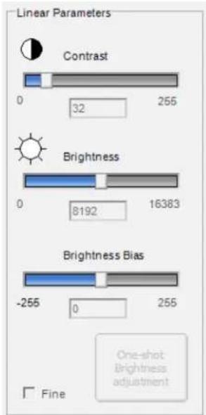
Manual: In this mode, image Contrast (gain) and Brightness (level) are entered completely manually via the sliders. The scene is mapped using a linear transfer function. Upon entry into the manual mode, currently-stored values of brightness and contrast are applied (i.e. the power-on defaults or the last saved values). The brightness adjustment is ranges from 0 to 16383 and spans the 14-bit data. The One-shot brightness adjustment button can be used to set the brightness in Manual mode. This finds the mean of the 14-bit histogram and sets it as the value for the brightness. This is the same method as used in Once-Bright and Auto-Bright.
Linear Histogram: Image contrast and brightness (gain and level) are optimized automatically based on scene statistics using a linear transfer function. Controls for the ITT Mean (sets gray scale midpoint) and Max Gain (AGC gain) are adjustable by entering the value in the Automatic Parameters section. The Linear Histogram algorithm uses scene statistics to set a global gain and offset (contrast and brightness) for the image. The Tail Rejection control determines what percentage of the outermost values of the histogram to remove when performing the algorithm. Upon entry into the linear histogram mode, the currently stored values are applied (i.e. The power-on defaults or the last saved values).
Note: In Manual mode and Once Bright mode, the brightness setting must be updated as the camera scene changes. To avoid this issue, it is recommended to use Automatic, Linear Histogram, or Auto Bright modes when possible. Also, AGC mode will only affect the digital data output if the Digital Video output mode is set to 8-bit data. The 14-bit digital data bypasses the AGC sections of digital processing.
Linear Parameters: Used for fine tuning the Auto Bright, Once Bright, and Manual modes, these settings are contextually active depending on which Algorithm is selected. Each of their settings is described above.
Once Bright - Only the Contrast control is active.
Auto Bright - The Brightness Bias and Contrast controls are active.
Manual - The Brightness and Contrast controls are active.
Automatic Parameters: Used for fine tuning the Histogram Equalization Modes and Linear Histogram modes, these settings are contextually active depending on which AGC algorithm is selected. Each of their settings is described above as they pertain to the particular Algorithm. AGC Filter sets the dampening factor that determines how quickly the AGC algorithm will adjust to changes in the scene. This ranges from 1 to 255 and higher numbers update faster.
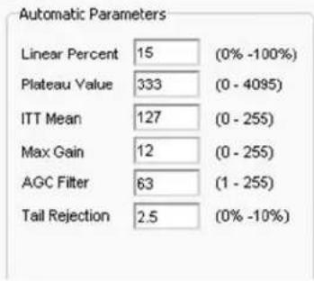
Automatic, CLAW, Entropy Based, and Auto /Entropy Based – The Linear Percent, Plateau Value, ITT Mean, Max Gain, AGC Filter, and Tail Rejection controls are active.
Linear Histogram - The ITT Mean, Max Gain, AGC Filter, and Tail Rejection controls are active.
Dynamic Digital Detail Enhancement (Dynamic DDE) filter: The DDE algorithm sets edge enhancement dynamically proportional to the number of bins occupied in the image histogram.
In a high contrast scene, the gain will be higher than in a low contrast scene. This allows faint details to be visible in high contrast scenes without increasing temporal and fixed pattern noise in low contrast scenes.
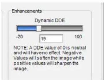
The DDE filter operates independently from the AGC and will enhance edges without affecting brightness or contrast. The algorithm operates on the high frequency data in the image to sharpen edges and lines. The valid range of Dynamic DDE setting is from -20 to 100 with 0 being the neutral setting where the filter has no effect. Settings below 0 will smooth the image reducing the appearance of sharp edges. Higher DDE settings will enhance all image non-uniformities resulting in a very detailed but more grainy picture, especially in high dynamic range scenes. Some users may choose to minimize image temporal noise and set the DDE to a negative value and thus create a more smooth image. Typical factory settings are between 15 and 30. Use the slider to adjust the setting, or select the text field and type in the desired setting.
5.5.1 AGC ROI Tab
FLIR cameras allow the user to set a Region of Interest (ROI) or a rectangular area of pixels on the sensor array that the AGC algorithm will use for its calculations. The AGC ROI applies to the Automatic and Linear Histogram algorithms. The ROI can be set for either the entire frame size (-320,256,320,-256) or some smaller portion. The ROI tab provides both a Window Editor and text entry coordinates to control the size and location of the Region of Interest (ROI). The Set button must be clicked for any changes to take effect. The AGC ROI is one of the largest factors in improving image quality. It can be used to ignore the sky or other large objects that would otherwise be used for calculation of AGC.
The AGC ROI is set using the full resolution of the sensor (640x512). When zoom is other than 1X, the ROI will scale with Zoom. When a small initial ROI is set and then zoom is performed, the ROI may need to be adjusted for optimal AUTO video.
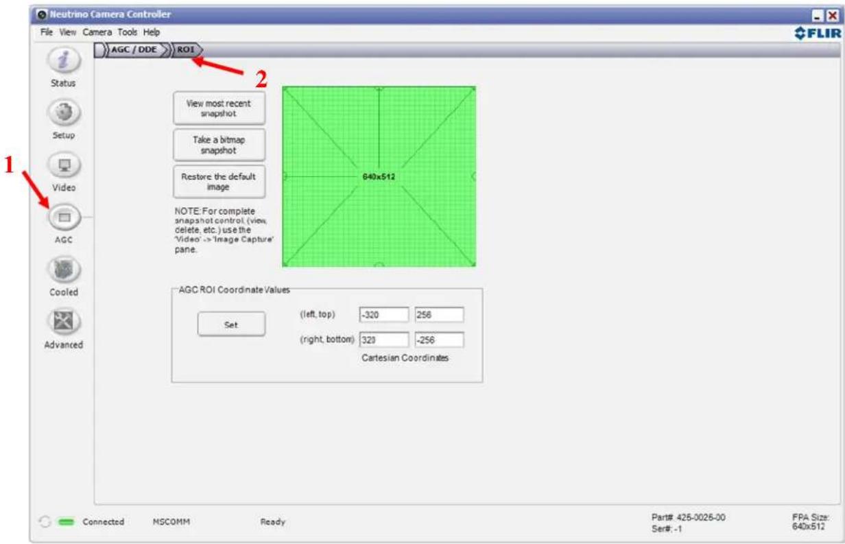
Figure 29: FLIR Camera Controller GUI – AGC ROI Tab
Window Editor: Use the mouse to drag the green ROI rectangle to any location on the FPA. The size of the ROI rectangle (in pixels) is displayed. To change the size of the ROI rectangle, drag one of the corner or side bubbles. The Set button must be clicked for changes to take effect.
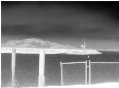
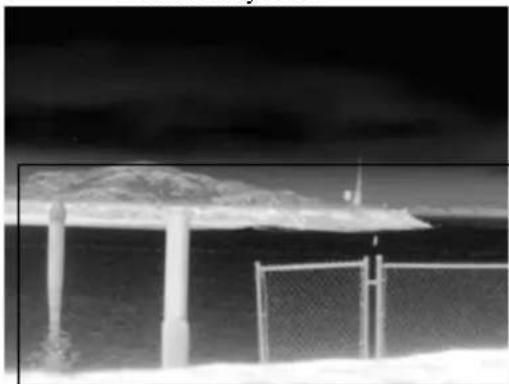
Snapshot: The Neutrino camera is configured with the ability to take snapshots. This feature allows snapshots to be taken and viewed as the background to aid in setting the ROI for a particular scene. Below is the ROI encompassing the entire FOV and the second has the ROI cropped to improve contrast on the portion of the scene most important to the user.
natural_image
Black-and-white photo of a coastal scene with a distant mountain and a chain-link fence, no visible text or symbols.Entire Array ROI
natural_image
Black-and-white photo of a beach with a large canopy and a chain-link fence, no visible text or symbolsSky excluded from ROI
Figure 30: AGC ROI Example
AGC ROI Coordinate Values: The settings use an X-Y coordinate system with (0, 0) being at the center of the sensor array. The upper two numbers marked (left, top) are the pixel coordinates of the upper left corner of the ROI rectangle. The lower two numbers marked (right, bottom) define the lower right corner of the ROI rectangle. The example to the right
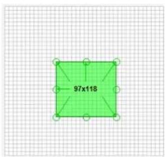
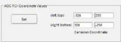
shows a full screen ROI for a 640x512 camera. The Set button must be clicked for changes to take effect.
Note: The AGC ROI coordinates are static relative to the image orientation. If the second image above was inverted, then the AGC ROI would still be cropped to exclude the sky in the inverted image and the increased contrast would still be visible on the land portion of the image.
5.6 Cooled Tab
The Cooled Tab provides controls applying only to cameras with cooled FPAs, including Neutrino.
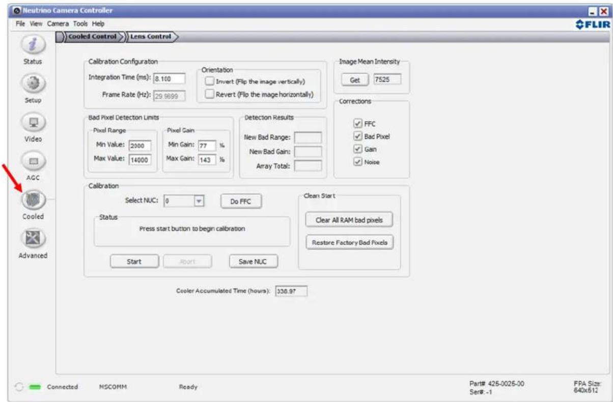
Figure 31: FLIR Camera Controller GUI – Cooled Tab
On the Cooled Tab, it is possible to select one of four Non-Uniformity Correction (NUC) tables, each with its own set of parameters (particularly integration time and invert/revert status). These four tables will have been configured and optimized as described below at the factory but their configuration can be changed as desired to optimize any particular image.
Integration Time: The Integration Time text box is used to set the integration time in milliseconds. The integration time is similar to the exposure time of a standard daylight camera and is the time per frame during which charge is collected. The camera operates in "snapshot" mode, meaning that charge is collected on the entire array of pixels at the same time. The range of integration times which can be set is 0.005 to 33
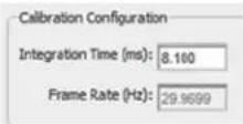
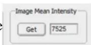
milliseconds. Short integration times should be used for viewing hot objects, while long integration times are used for colder objects. If too short or too long integration times are used, the image will appear non-uniform and will seem to be non responsive to the signal, so some experimentation is required to determine the best integration time for the scene being imaged. Using the Image Mean Intensity feature will assist in determining the best integration time. An integration time resulting in good imagery for a typical
application is when the camera is “looking” at the scene of interest and the image mean intensity is between 6000 and 8000.
Frame Rate: The Frame Rate box will either display 29.9699 (for NTSC, or 25 for PAL) for Free Run mode, or “external” if one of the External Sync modes is operational.
Orientation: The Orientation check boxes work the same as described in the Video Tab section above. They can be different for each NUC table. To optimize the image, a 2-point NUC process, as described below, should be performed each time these settings are changed.
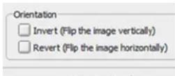
Image Mean Intensity: Each time the “Get” button is pressed, the camera will calculate the average intensity value of the entire array, in 14-bit A/D counts (0-16383). The range of values will not span the entire A/D converter range, but will be about 500 to 15800 counts.
Bad Pixel Detection Limits: These are the parameters outside of which a pixel is considered “bad” during the 2-point NUC process. The Min and Max Pixel Range parameters define the limits of the absolute value in A/D counts within which each pixel must fall in order to be considered good. The Min
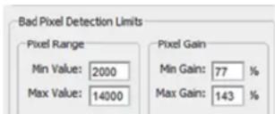
and Max Gain parameters are the limits of the gain correction factors by which the pixel values must be multiplied in order to be equal to the array average value.
Detection Results: These boxes show the bad pixels resulting from the last 2-point NUC performed. The significance of the word "New" is that those boxes only report pixels which were not already in the bad pixel map for that NUC. Note that if a good NUC has already been performed, and unless the Clear All RAM Bad Pixels button has been pressed, they will usually be 0. Also, the gain bad pixel calculation is done first,
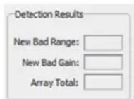
and only those pixels which are not gain bad pixels will be reported as bad range. The Array Total will always report the total bad pixels in the bad pixel map, whether they come from the last NUC or were there before.
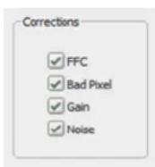
Corrections: The Corrections check boxes turn on and off the NUC corrections for the camera. These states are saved with the Save Settings command and so are global rather than applying separately to each NUC table. The FFC box turns on or off the application of the offset table, the Gain box turns on or off the application of the gain table, and the Bad Pixel box turns on or off the bad pixel replacement function. The Noise box turns on and off a temporal noise filter which will reduce the temporal noise of the camera by about a factor of two without otherwise affecting the image.
Calibration: The Calibration area is the heart of the Cooled Tab, where the most important functions are
performed. First the desired NUC table to be calibrated should be selected using the Select NUC pulldown. Then the integration time should be set appropriately to the scene temperatures to be imaged. The Image Mean Intensity is useful in doing this. Two uniform, flat black sources are needed for the 2-point correction and it is best if they span a large part of the range of scene temperatures to be imaged. Blackbody sources are ideal for this purpose. The Image Orientation and Bad Pixel Detection Limits also need to be set appropriately before the process is started. Now push the Start button to initiate the 2-point NUC process. Follow the prompts to place the hot and cold sources in front of the camera so they fill the field of view. A message will appear when the process is complete. The Abort button will be active during the NUC process. When the NUC process is complete, check to see that the image is good and the number of bad pixels found is not unreasonably high, then press the Save NUC button to save the NUC parameters. The NUC parameters include a header with the selections relevant to that NUC (integration time, invert/revert, etc.), a gain table with the gain values for each pixel, and an offset table with the offset values for each pixel. If a pixel is found to be bad, a bit is set in the gain table for that pixel indicating its status and the value of the average of the eight nearest good neighbors is substituted in the image. If it is not desired to Save the NUC, reselecting it will return to the NUC table values which were active before the process was initiated.
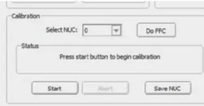
Do FFC: This button will cause the camera to do a one-point (offset only) NUC correction. A uniform
flat black source should be placed in front of the camera before pressing this button. This function is useful to achieve the most uniform correction possible, for example if the camera power has been cycled since the last 2-point NUC has been performed.
Clear All RAM Bad Pixels: This button is used before performing a 2-point NUC if a new bad pixel table is desired. Note that a warning text will come up saying that the gain table will be initialized during this
process. Therefore a new 2-point correction will need to be performed subsequently in order to generate a satisfactory image.
Restore Factory Bad Pixels: A bad pixel map will be generated at the factory during Acceptance Testing which will include pixels which will not be found by the standard 2-point NUC, such as noisy or flickering pixels. This map should always be installed to give the best image. It will need to be Restored if the Clear All RAM Bad Pixels function is used. As mentioned below in Section 5.7.1, the bad pixel map can always be viewed by pressing the BP Map button on the Bad Pixel Elimination Tab. Important: If the image for that NUC table is to be Inverted or Reverted, first set the Orientation to Normal (not Inverted or Reverted), then Restore the Factory Bad Pixels, then reset the Orientation to the desired configuration for that NUC table.
5.6.1 Lens Control Tab
Functions in the Lens Control Tab are not part of the Neutrino initial release.
5.7 Advanced Tab
The Advanced Tab contains many features that can be considered to be for advanced users. For this reason, a special keystroke and password is required to display the Advanced Tab. The keystroke is Ctrl+Shift+a and the password is www.flir.com. After the keystroke is performed, the following dialog will appear. Note that the text in the following image is added and a password typed will display as asterisks.
This is only intended for sophisticated users and it is possible to break the camera if an incorrect operation is performed. If it is desired that other users have access to GUI but they should not have access to the Advanced page, it can be disabled on the View pulldown menu by unchecking Advanced. Note that the Logger pane described in the description of the View pulldown above is shown in this screen shot.
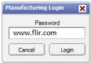
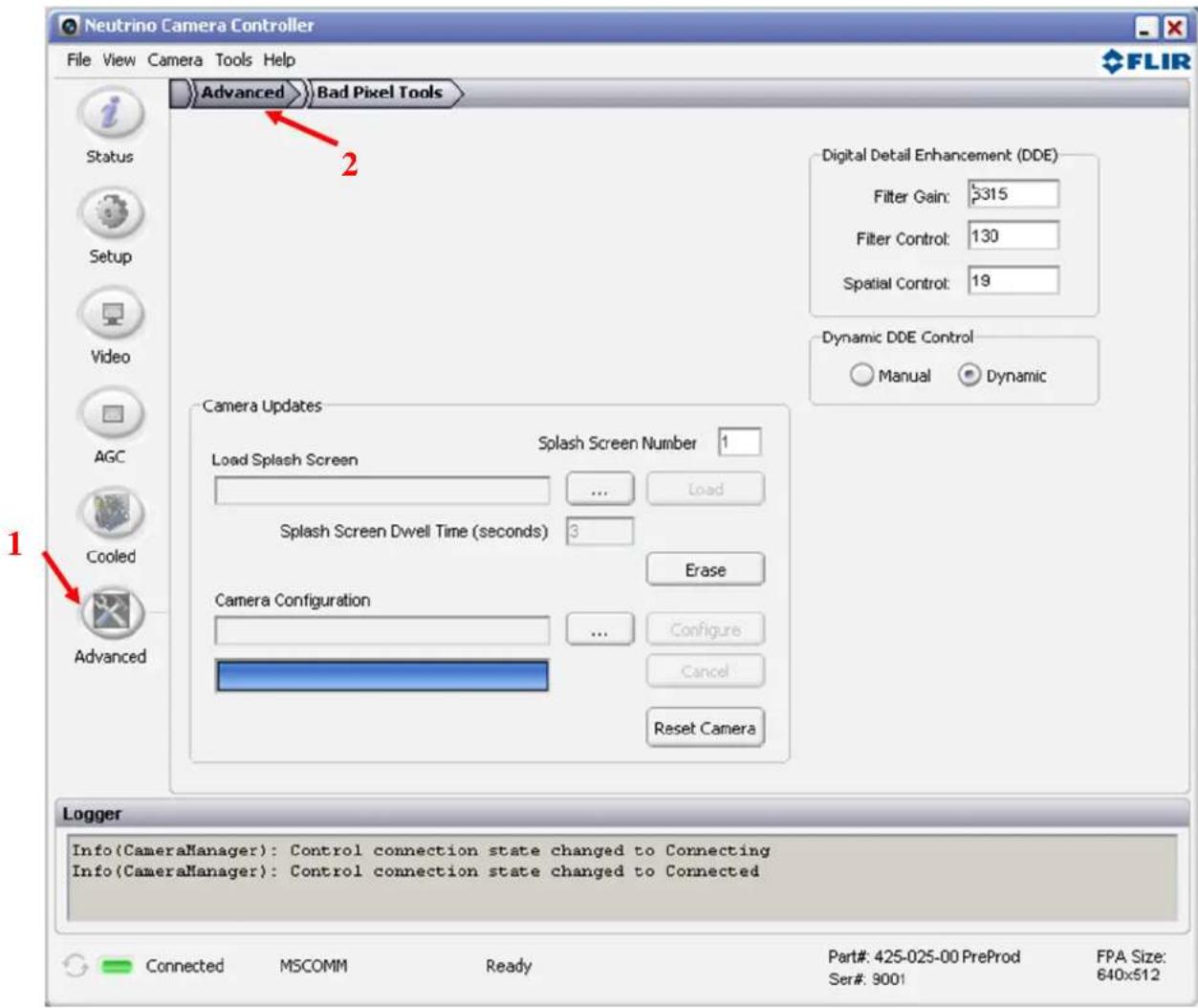
Figure 32: FLIR Camera Controller GUI – Advanced Tab
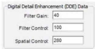
Digital Detail Enhancement (DDE) Data: These settings apply when the camera is in manual DDE mode. This mode is only recommended for advanced users that understand these parameters and plan to manually adjust them. They are set automatically when in Dynamic DDE mode using the slider on the AGC Tab. Use Factory Defaults to recover from inappropriate settings.
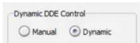
Dynamic DDE Control: Select manual or dynamic DDE mode. Manual DDE mode is only recommended for advanced users.
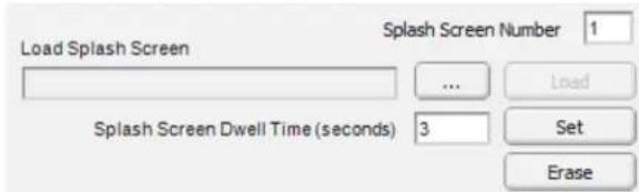
Splash Screen: It is possible to load a custom 256 color bitmap for display in the analog video output at start-up. Consult FLIR for more information. The Neutrino camera supports only one Splash Screen at a time and the Dwell Time will be only a couple of seconds if the FPA is cold, or the full cooldown time of the FPA if the FPA is warm. Erasing the Splash Screen on a Neutrino camera will result in a black Splash Screen.
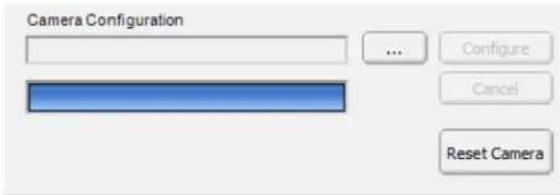
Camera Configuration: This is used to load "pcf" files into the camera that can perform a wide variety of functions such as updating firmware and/or software, or loading splash screen,. Consult FLIR before using this function.
5.7.1 Bad Pixel Elimination Tab
This tab requires access to the Advanced Tab. Refer to section 5.7 for instructions. All defective pixels are identified by FLIR as part of the standard factory Acceptance Test and during the 2-point NUC process described in the Cooled Tab section. However, it is possible that a camera in the field may have a pixel that needs replacing. Usually these are flickering pixels, or pixels which have developed an offset, and so appear as white on a black background, for example.
When eliminating pixels, it is important that the camera is not inverted and not reverted (See section 5.3).
The bad pixel kill procedure involves taking a snapshot of a scene that clearly shows the bad pixel.
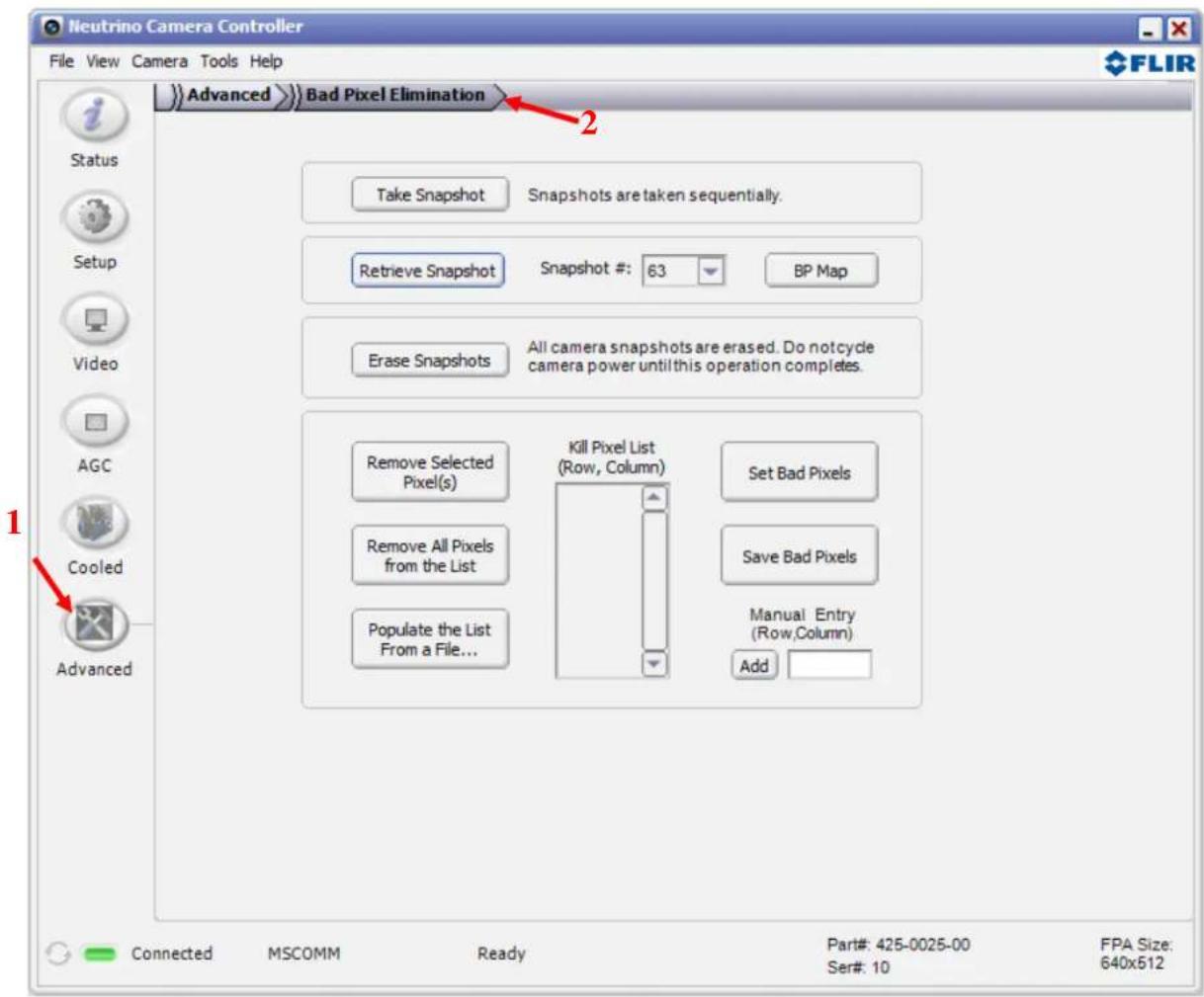
Figure 33: FLIR Camera Controller GUI – Bad Pixel Elimination Tab
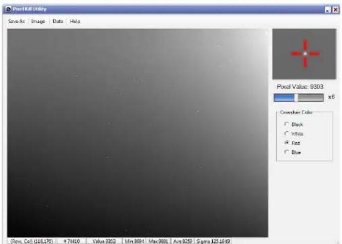
Once a snapshot is taken, Retrieve Snapshot will open a window similar to the Snapshot Viewer in Image Capture, but there is an additional pane on the right that shows a reticle with a zoomed subframe. Use the mouse, then the arrow keys to fine tune the cursor location until the offensive pixel is between the crosshairs. The zoom value of the subframe can be adjusted using the slider bar. Click Help on this window for more information on the Pixel Kill Utility.
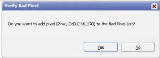
Use the Enter key to select the pixel and add it to the pixel kill list.
Bad pixels can also be manually added to the list by entering the row and column, as shown to the right, and clicking Add.
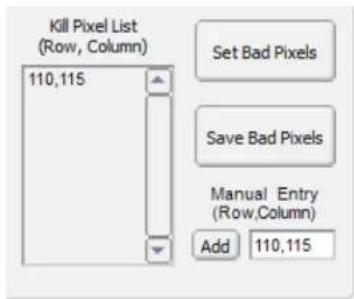
Bad pixels can be removed from the Kill Pixel List by selecting them one by one and clicking Remove Selected Pixels. Use Ctrl to select multiple pixels or Shift to select a group of pixels to be removed. There is also a Remove All Pixels from the List button that will clear the list.
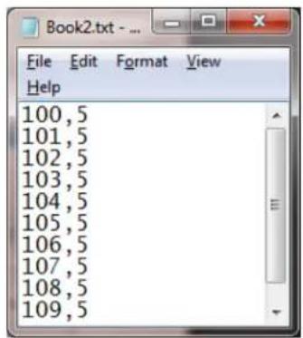
The list can be populated from a txt file. The format should be as follows:
Once the list is populated, click Set Bad Pixels to add these pixels to the camera's bad pixel map. This will immediately affect the video output. Verify that the pixel is being replaced and click Save Bad Pixels to save this change in the camera. If the pixels are not being replaced, reset the camera using the Setup Tab to revert back to the previous state.
BP Map The bad pixel map currently in the camera can always be displayed by pressing this button. Bad pixels will appear as white on a black background.
This documentation contains proprietary information to FLIR Systems, Inc. This information must be maintained in confidence and used only in a manner consistent with the documentation and any executed Non-Disclosure Agreement, and may not be disclosed to any third parties without FLIR's written consent.
© FLIR Commercial Systems, 2011. All rights reserved worldwide. No parts of this manual, in whole or in part, may be copied, photocopied, translated, or transmitted to any electronic medium or machine readable form without the prior written permission of FLIR Commercial Systems
Names and marks appearing on the products herein are either registered trademarks or trademarks of FLIR Commercial Systems and/or its subsidiaries. All other trademarks, trade names, or company names referenced herein are used for identification only and are the property of their respective owners.
Liberation fonts are copyright 2009 by RedHat and are used under authority of the GNU public license. Information about these fonts and the GNU public license can be found at : https://www.redhat.com/promo/fonts/.
This product is protected by patents, design patents, patents pending, or design patents pending.
If you have questions that are not covered in this manual, or need service, contact FLIR Commercial Systems Customer Support at sba-cores@flir.com for additional information prior to returning a camera.
This documentation is subject to change without notice.
This equipment must be disposed of as electronic waste.
Contact your nearest FLIR Commercial Systems, Inc. representative for instructions on how to return the product to FLIR for proper disposal.
FCC Notice. This device is a subassembly designed for incorporation into other products in order to provide an infrared camera function. It is not an end-product fit for consumer use. When incorporated into a host device, the end-product will generate, use, and radiate radio frequency energy that may cause radio interference. As such, the end-product incorporating this subassembly must be tested and approved under the rules of the Federal Communications Commission (FCC) before the end-product may be offered for sale or lease, advertised, imported, sold, or leased in the United States. The FCC regulations are designed to provide reasonable protection against interference to radio communications. See 47 C.F.R. §§ 2.803 and 15.1 et seq.
Industry Canada Notice. This device is a subassembly designed for incorporation into other products in order to provide an infrared camera function. It is not an end-product fit for consumer use. When incorporated into a host device, the end-product will generate, use, and radiate radio frequency energy that may cause radio interference. As such, the end-product incorporating this subassembly must be tested for compliance with the Interference-Causing Equipment Standard, Digital Apparatus, ICES-003, of Industry Canada before the product incorporating this device may be: manufactured or offered for sale or lease, imported, distributed, sold, or leased in Canada.
EU Notice. This device is a subassembly or component intended only for product evaluation, development or incorporation into other products in order to provide an infrared camera function. It is not a finished end-product fit for general consumer use. Persons handling this device must have appropriate electronics training and observe good engineering practice standards. As such, this product does not fall within the scope of the European Union (EU) directives regarding electromagnetic compatibility (EMC). Any end-product intended for general consumer use that incorporates this device must be tested in accordance and comply with all applicable EU EMC and other relevant directives.
- Table of Contents
- Neutrino .... 1
- TABLE OF FIGURES
- Document
- Scope
- Unpacking the Camera
- Basic Accessories
- VPC Module Accessory
- Camera Link Module Accessory
- Connecting to the Camera
- FLIR Camera Controller GUI
- Physical Connection
- Software Connection
- Digital Data via Camera Link
- Click Apply and Start Grab
- Troubleshooting the FLIR Camera Controller GUI
- Operation of the FLIR Camera Controller GUI
- Menu Bar
- Status Tab
- Setup Tab
- Video Tab
- Digital Video Tab
- Image Capture Tab
- Manage Snapshots
- Destination Folder ...
- AGC Tab
- Histogram Equalization Modes:
- CLAW:
- Irradiance Specific Contrast Adjustment (ISCA):
- Legacy Modes:
- AGC ROI Tab
- Cooled Tab
- Lens Control Tab
- Advanced Tab
- Bad Pixel Elimination Tab
Brand : FLIR
Model : Neutrino
Category : Uncategorized