
Latitude 9.2 - Uncategorized FLIR - Free user manual and instructions
Find the device manual for free Latitude 9.2 FLIR in PDF.


| Product Type | Rugged thermal imaging tablet |
| Brand | FLIR |
| Model | Latitude 9.2 |
| Dimensions (approx.) | 310 x 210 x 25 mm (12.2 x 8.3 x 1.0 in) |
| Weight (approx.) | 1.6 kg (3.5 lbs) |
| Display | 9.2-inch sunlight-readable touchscreen |
| Power Supply | Removable Li-ion rechargeable battery, 12V DC input |
| Thermal Imaging | Integrated FLIR thermal camera with radiometric temperature measurement |
| Operating System | Windows 10 / Android (depending on variant) |
| Memory | 8 GB RAM, 256 GB SSD (typical) |
| Connectivity | Wi-Fi, Bluetooth, USB 3.0, HDMI, Ethernet |
| IP Rating | IP65 (dust and water resistant) |
| Drop Test | MIL-STD-810G, 1.2 m (4 ft) onto concrete |
| Main Functions | Thermal inspection, data logging, report generation, video streaming |
| Storage Temperature | -20°C to 60°C (-4°F to 140°F) |
| Operating Temperature | -10°C to 50°C (14°F to 122°F) |
| Cleaning and Maintenance | Clean lens with soft, dry cloth; avoid solvents; keep vents clear |
| Safety | Laser safety: Class 1 laser product (if equipped); follow local regulations |
| Spare Parts and Reparability | Battery and storage are field-replaceable; other repairs by authorized service center |
Frequently Asked Questions - Latitude 9.2 FLIR
User questions about Latitude 9.2 FLIR
0 question about this device. Answer the ones you know or ask your own.
Ask a new question about this device
Download the instructions for your Uncategorized in PDF format for free! Find your manual Latitude 9.2 - FLIR and take your electronic device back in hand. On this page are published all the documents necessary for the use of your device. Latitude 9.2 by FLIR.
USER MANUAL Latitude 9.2 FLIR
© 2022 FLIR Systems, Inc. All rights reserved worldwide. No parts of this manual, in whole or in part, may be copied, photocopied, translated, or transmitted to any electronic medium or machine readable form without the prior written permission of FLIR Systems, Inc.
Names and marks appearing on the products herein are either registered trademarks or trademarks of FLIR Systems, Inc. and/or its subsidiaries. All other trademarks, trade names, or company names referenced herein are used for identification only and are the property of their respective owners. This product is protected by patents, design patents, patents pending, or design patents pending. The contents of this document are subject to change.
FLIR Systems, Inc.
6769 Hollister Avenue
Goleta, California 93117
USA
Phone: 888.747.FLIR (888.747.3547)
International: +1.805.964.9797
For technical assistance, call us at
+1-800-254-0632 or visit the
Teledyne FLIR Support page
at www.flir.com/support
Important Instructions and Notices to the User:
Modification of this device without the express authorization of FLIR Commercial Systems, Inc. may void the user's authority under FCC rules to operate this device.
Document History
| Version | Date | Comment |
| 1 | May 2022 | Initial 9.2 Release |
Table of Contents
1. Introduction ...... 1
1.1 Scope 1
1.2 Finding what you need .... 1
1.3 Intended Audience 1
1.4 More Information – Help System 2
1.5 About this File 3
2. FLIR United VMS Latitude System Overview and Main Components 5
2.1 Servers 5
2.2 Latitude Clients - Admin Center, Control Center and EZ Web Client 6
2.3 Security for your FLIR United VMS Latitude System 8
System - System Security 92.3.1
System - Edge Security 112.3.2
3. Licensing your VMS 15
4. Using the Quick Configuration Wizard (QCW) 21
4.1 QCW – Prerequisites 21
4.2 Starting the QCW 22
4.3 QCW - Global Settings 23
4.4 QCW – Archivers 24
4.5 QCW – Adding a Network ...... 26
4.6 QCW-Configuring Archiver Storage 28
4.7 QCW - Discovery 30
4.7.1 Automatic Discovery 32
4.7.1.1 Discovering FLIR cameras and Encoders 34
4.7.2 Manual Discovery 34
4.7.3 Adding Generic Cameras 36
4.8 QCW - Attach Cameras to Archiver 37
4.9 QCW – Quality 39
4.10 Accessing Applications from the Sidebar 40
4.11 Accessing Wizards from the Sidebar 41
5. Setting up Cameras in the Latitude System 42
5.1 Individual Camera Settings – the Camera Parameter Screens 43
5.1.1 General Tab 43
5.1.2 Video Settings Tab 44
5.1.3 Picture Settings Tab 44
Recording Settings Tab 445.1.4
5.1.5 Linked Tab 45
Table of Contents
5.1.6 PTZ Tab 45
5.1.6.1 PTZ Controls 46
5.1.7 Motion Detection Tab 48
5.1.8 Privacy Masking Tab 51
5.1.9 Actions Tab 51
5.2 Setting up Groups of Cameras .... 52 Using ‘Copy Configuration’ .... 525.2.1
6. Setting up other Entities 54
6.1 Microphones and Speakers 54
6.1.1 Define a Microphone or Speaker 54
6.1.2 Link a microphone and/or speaker to a camera 55
7. Logical Configuration 57
7.1 Enterprises and Sites 57
7.2 Sequences 58
8. Setting up Specialized Servers 60
8.1 Web Server 60
8.2 Transcoder Server 61
8.3 Gateway Server 62
8.4 Case Builder Server 63
9. Alarm Management 64
9.1 Set up Alarm Types 65
9.2 Set up how the Alarm is Triggered 69
10. User Management 70
10.1 Defining User Groups and Users 71
10.1.1 Access Rights 72
10.1.2 Privileges 73
10.2 Inheritance 73
11. APPENDIX 1 - 'How to' Configuration Information .... 75
11.1 Tips and Tricks using the Latitude Interface 75
11.1.1 Foldaway Bars 75
11.1.2 Using 'Switch View' or clicking a node 76
11.1.3 Dialogs boxes appear when the item is selected 77
Search Bar Highlight mode 7811.1.4
11.2 Define Coverages from the System Settings View 78
11.3 Create a Coverage in System Settings 78
11.4 Choose an Existing Coverage from the Camera Screen 79
Table of Contents
11.5 Define a New Coverage from the Camera Screen 79
11.6 Create a Video Profile (using System Settings View) 80
11.7 Video Profile Parameters 80
11.8 Video Profile 81
11.9 Create Schedules (using System Settings View) 81
11.10 Create a New Schedule 83
11.11 Configure Actions and Events 84
11.12 Binding Encoders and Cameras 85
11.13 System-Wide Events 86
11.14 TLS - Setting up Encryption to/from Web Clients 87
12. APPENDIX 2 - Admin Center - User Interface Details 88
12.1 Main Screen 89
12.2 Sidebar 90
12.3 Dashboard 94
12.3.1 Camera Pane 94
12.3.2 Users Pane 95
12.3.3 Archivers and Storage Pane 95
Recorded Stream Quality Pane 9612.3.4
12.3.5 Database Health Pane 96
License Information Pane 9612.3.6
12.4 Navigation Tree Pane 97
View Dropdown - Navigation Tree Pane 9712.4.1
12.4.2 Navigation Tree Tools .... 97
Selection Pane Tools – 'Add' options depending on current view .... 9812.4.3
Selection Pane Tools – 'Filter' options depending on current view .... 9912.4.4
12.5 Configuration Pane 100
Configuration Pane Tools 10112.5.1
13. APPENDIX 3 - License Information .... 102
13.1 License Components 102
13.2 Licensing the Failover Directory 103
13.3 Failover Directory License File Installation 103
14. APPENDIX 4 - Installation Overview .... 104
14.1 Installation Prerequisites 104
14.2 Installation Process 104
15. APPENDIX 5 - Terminology .... 105
1 Introduction
1.1 Scope
This document is designed to allow Administrators to get up-and-running with the minimal basics of the system and is not intended to replace the user documentation or training. This document does not cover best practices nor makes any assertions as to the recommended practices or design of physical security.
Administrators should be familiar with physical security basics, practice due diligence, and observe applicable laws regarding their use of the system in the various jurisdictions within which they operate it and its features.
This document is limited in scope and does not attempt to teach security principles or hardware installation. It is provided to allow licensed and knowledgeable security users a quick-start overview of the systems basic features and configurations.
This document covers the AdminCenter for United VMS 9.2.
1.2 Finding what you need
Introducing the System and getting started
- Introduction: Introducing this guide, this section provides background information – who is intended to use the guide, tips on where to find more information, should you need it, and a short overview of the system.
- Licensing your VMS: Preparing for a Latitude System and applying your Latitude license.
Configuring the System
-
Using the Quick Configuration Wizard (QCW): The Quick Configuration Wizard leads you through the initial Latitude System setup.
-
Setting up Cameras in the Latitude System: This section takes you through the process of configuring cameras.
-
Setting up other Entities: Adding microphones and speakers.
-
Logical Configuration: Tailoring the system to match your structure.
-
Setting up Specialized Servers: Transcoder, Gateway, Case Builder, and Web Server.
-
Alarm Management
-
User Management
Appendices with detailed information
Appendix 1 - 'How to' Configuration Information
Appendix 2 - Latitude Admin Center - User Interface Details
Appendix 3 - Latitude License
Appendix 4 - Installation Overview
Appendix 5 - Latitude Terminology
1.3 Intended Audience
This guide is written for Latitude AdminCenter administrators, who are responsible for setting up the system, adapting it to fit the needs of the site, and keeping it running. Admin Center
users must be able to set up facilities for Latitude ControlCenter/s operators, who are the primary users of the Latitude Video Management System.
In this guide, we try to cover the basic setup of the system.
A separate publication, Latitude ControlCenter Quick Reference Guide, covers the operation of the ControlCenters.
1.4 More Information – Help System
Once you have completed the initial installation of the system and you have the AdminCenter running, you'll find that there is an extensive context-sensitive Help system available at all times, that is accessed by clicking the symbol in the top right-hand corner of the screen. The Help system defines all system parameters and also provides information on using the Latitude System's features.
![FLIR AdminCenter System Logical View General System Security Edge Security Logical QIs Discovery Task 9.2.0.1000 Configuration Name: File 12.0.1.000 Description: Reconciliation System System ID: Refractor Where Discarding Space Is Full Video Time Child Letters System PTZ Priority System security System is user site interested User is user role interested Stream Connection Types Default acquired line connection type Default author recording connection type Default clients connection type Identifying Alarm Property Followover Archive Concurrent logms FLIR AdminCenter Help File 9.2 System Interface Status - [ ] Help - Contents Getting Started System Overseas AdminCenter User Interface Configuration - limited Analog Monitor Audio Layering (Stage) Camera Camera Sequence Conditional Event Enterprise V3 Maps Input for Device Map Microphone Network Output for Device Respuser Group Serial Device Social CCTV Keyboard Site Speaker System Configuration This can configure the following parameters: Name: System key name. Database: The web-based configuration system; Systems: All: The input off user for location recognition in the ControlCenter. See working with Passwords for more information. Behavior When Recording Space is Full The following options are available for the existing scanning when an archive is enclosed space to be deleted and all are inserted by us are unchanged. Stop scanning. While protected, the Author about recording time class. This prevents surviving non-apply data before being saved or allowed. Hardware will matching scanning. When checked, the Author overwrites which drops according to explanation on your file and then to send. Water locked off the user room from. FLIR AdminCenter Help File 9.2 System Interface Status - [ ] System PTZ Options • Internal Connection Types • Identifying Device Options • Failure Options • Concomer Logms • Directory Backup Schedule FLIR AdminCenter Help File 9.2](/content/2026/05/943976/images/768d4be62937b19f5fa0495f73226bd3875a7de22139f0999945b12360fbfead.jpg)
Figure 1 - Accessing Latitude Online Help
1.5 About this File
Welcome to the United VMS 9.2 Latitude Admin Center User Guide.
Note: Changes to this file were last introduced after Application Build No: 3300
Summary of latest changes:
| Change | Date Changed | Summary | Links |
| Release | April 2022 | Updated version and build for release. |
Changes introduced in Rel. 9LU:
This table is retained for Users upgrading from previous releases
| Change | Date Changed | Summary | Links |
| September <?> 2022 | 9.2.1 release | ||
| April 2022 | 9.2 Release | ||
| Licensing | July 2017 | Licensing URL changed | Licensing your VMS |
| System Security | July 2017 | Changes to wording of System Security parameters. New warning message introduced for Edge Device page for users of Quasar Gen II and IOI-HD units. | Security for your FLIR United VMS Latitude System |
| Licensing | May 2017 | A new Licensing method was introduced. | Licensing your VMS |
| System Security | May 2017 | Facilities added for securing communications with edge devices and web clients | Security for your FLIR United VMS Latitude System |
| Discovering FLIR Edge Devices | May 2017 | New facilities introduced to simplify discovery of FLIR edge devices | Discovering FLIR cameras and Encoders |
| Binding Cameras and Encoders | May 2016 | The ability to associate an Encoder with a camera, to provide Analytics functionality or PTZ tracking. | Binding Encoders and Cameras |
| TLS | May 2016 | Transport Level Security is available on communications between the Web Server and any connected Web Clients.The user is responsible for acquiring and installing a suitable Certificate. | TLS - Setting up Encryption to/from Web Clients |
| Generic Cameras | May 2016 | Adding non-ONVIF-compliant Generic Cameras | Adding Generic Cameras |
Note: These are not a formal Change Register - the lists are included so that users can quickly access Topics that contain new or changed information.
File information:
Source file: Latitude_AdminCenter_9.2_User_Guide Date compiled:Tuesday, May 10, 2022 pdf
2 FLIR United VMS Latitude System Overview and Main Components
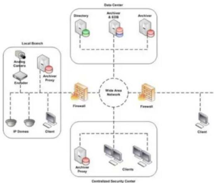
The FLIR United VMS Latitude system is a network-based video and audio management system comprised of servers, client workstations, connected edge devices (e.g. encoders, decoders, IP cameras, etc.) and additional optional components, such as external storage modules, sensors and keyboards.
flowchart
graph TD
    A["Data Center"] --> B["Directory"]
    A --> C["Anchor & EDB"]
    A --> D["Anchor"]
    B --> E["Firewall"]
    C --> F["Firewall"]
    D --> G["Client"]
    H["Centralized Security Center"] --> I["Archiver Proxy"]
    H --> J["Clients"]
    H --> K["Client"]
    L["Local Branch"] --> M["Analog Camera"]
    L --> N["Encoder"]
    L --> O["Anchor Proxy"]
    L --> P["IP Domes"]
    L --> Q["Client"]
    style A fill:#f9f,stroke:#333
    style H fill:#ccf,stroke:#333
    style L fill:#cfc,stroke:#333
Figure 2 - Schematic – a Latitude Network Video Management System
2.1 Servers
Directory Server
The Directory keeps all the configuration information about the system. This allows it to:
- Manage System Configuration Data
- Handle Alarm Management
- Handle Incident Management
- Manage failover in the event of a Server failure
EDB Server
The Event Distributor is used as an interface for passing events and actions between different Latitude components, as well as between the system and external devices and programs.
Archiver
The Archiver is a server that communicates with all the systems devices, and is responsible for the following:
- Pushing down settings such as resolution, frame rate etc.
- Recording
- Routing video to the various clients
Transcoder/s
The Transcoder is responsible for transcoding video content (Live and Playback). It can be set to downscale resolution and change video compression (for example to MJPEG), and by doing so it allows the system to transmit video over the internet.
Gateway Server
The Gateway Server acts as the interface to the system for remote or external connections.
CaseBuilder Server
The CaseBuilder enables operators with the appropriate system privileges to collect and organize data into Cases, and copy and export those Cases in a verifiable form to a shared location outside the Latitude system, so they can be accessed by other systems. For example, a Case may be taken off-site for third-party investigations or to a court of law.
Web Server
The Web Server enables internet-connected users to view live and recorded material, using the Web Client provided with the system. Transport Layer Security may be used to encrypt all Web Client communications.
Application Server
The Application Server is a component that is responsible for hosting SDK services.
2.2 Latitude Clients - Admin Center, Control Center and EZ Web Client
ADMIN CENTER CLIENT
The Latitude AdminCenter enables you to manage every aspect of the system, including camera settings, recording parameters, user access and privileges, alarm behavior, etc.
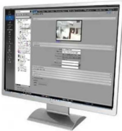
Figure 3 AdminCenter console showing a camera parameter screen
Once the system is configured and running, use the AdminCenter to monitor system health, add new devices when required, and to reconfigure the system when necessary.
The AdminCenter also enables operators to perform system data backup.
CONTROL CENTER CLIENT
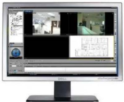
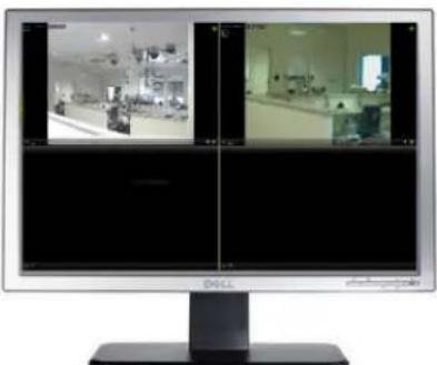
Latitude Control Centers are the consoles where operators can monitor selected live cameras, search for and view recordings, monitor alarms that are raised by the system or that are input manually, and respond to them.
natural_image
Computer monitor displaying multiple video feeds showing interior security operations (no visible text or symbols)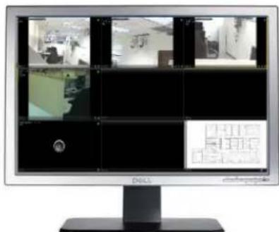
natural_image
Computer monitor displaying multiple security camera feeds and display screens (no visible text or symbols)Figure 4 A ControlCenter console set up with multiple monitors
The Latitude Control Center is highly configurable, and each Control Center can be set up to suit the needs of specific operators. Where computers are equipped with multiple screens, then each ControlCenter can spread its display over multiple monitors (as shown above).
WEB CLIENT
The Latitude Web Client enables authorized users on connected PCs to view live and recorded material, take snapshots, export clips and respond to alarms without the need to install any client software, just by using a supported Browser.
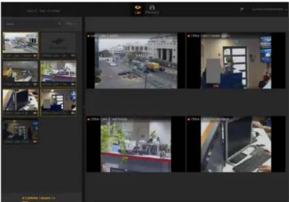
Figure 5 Web Client in a standard Browser
2.3 Security for your FLIR United VMS Latitude System
Security is becoming an increasingly important topic for users of computer systems - especially for those with large IP networks. For large VMS systems, apart from normal security considerations common to all computer systems and networks, several additional vulnerable areas need to be considered.
• Equipment from multiple vendors - each with their own widely-known default passwords
- Managing distributed configurations - needing to send control information to and from cameras
- Access via browsers - requesting and receiving video streams
FLIR United VMS Latitude provides security features to reduce the risks associated with these vulnerable areas.
The FLIR United VMS Latitude System entity setup includes two tabs that allow the user to set up security policies and administer them. A brief summary of the facilities available is provided below.

Deciding on security policies and implementing them requires in-depth knowledge of the alternatives, and users are urged to discuss these with their TELEDYNE FLIR support representatives when setting up their systems or making changes to the configurations.
The System Security Tab and Edge Security Tab are accessed from the System/General page in the Logical or Physical view..

Figure 6 Accessing the System Security and Edge Security Tabs
2.3.1 System - System Security
The System Security Tab has the following panes:
- Edge Security Settings
- Web Security
- Users Password Rules
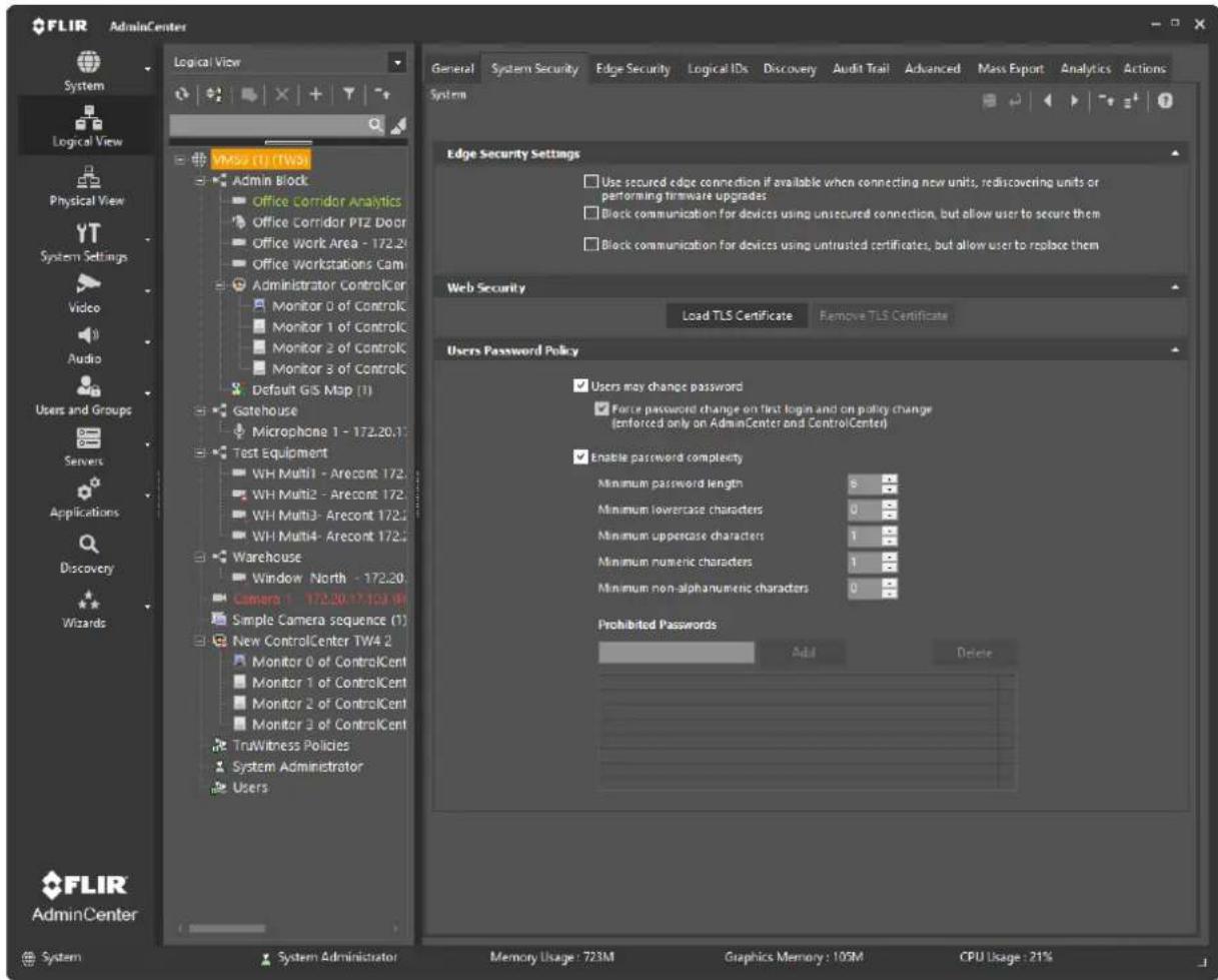
Figure 7 System Security Tab
Establishing and applying these facilities requires support in the system and from the edge devices themselves. Check the Admin Center Help file for details of what facilities are supported in your installed version.
TLS for Edge Devices – Choosing the options
The user sets under what conditions Edge Devices may communicate with the system.
Terms used here:
- Secured Connection - Communication uses HTTPS and encryption to ensure integrity of messages and guard against malicious users.
- Self-signed - Certificate is generated by the camera (or unit), rather than by a third-party Trusted Certificate Authority.
| Parameter | Comments | |
| Use secured edge connection if available:- Connecting new units- Rediscovering existing units- Performing firmware updates | IMPORTANT: APPLIES UNITS IN THE CASES SHOWN - Other Units already in the system are not affected.When this option is enabled, the Archiver attempts to establish a secured connection with the camera. When successful, all the communication with the camera is encrypted.Discover using FLIR Plug-in or ONVIF method.Units must support HTTPS and have certificate already loaded or have already created their own self-signed certificate. | |
| Block communications for devices using unsecured connection, but allow user to secure them | APPLIES TO ALL UNITS.Archiver blocks all communication from units except those actions that are required in order to set up secured connections.(More strict) | |
| Block communications for devices using untrusted certificates, but allow user to replace them | APPLIES TO ALL UNITS.Archiver blocks all communication from units except those actions that are required in order to replace the certificates.(Most strict) |
Step details to complete the TLS (Transport Layer Security) for Edge Devices set up is provided in the Admin Center Help file.
Web Security
This panel enables the user to activate and deactivate TLS encryption between the Web Server/Transcoder and any Web Clients that are in use. Step details to complete the TLS for Edge Devices set up is provided in the Admin Center Help file.
Users Password Rules
This panel enables you to create rules regarding passwords across the system.
Settings include:
- Disable rules
- Allow password to be identical to user name
- Minimum length
• Minimum number of letters
• Minimum number of digits
• Prohibited Passwords - Users may not change passwords
2.3.2 System - Edge Security
This page enables the following:
- Users to view the current Security mode for all units and where applicable
- Administrator to change settings (on devices that support these capabilities)
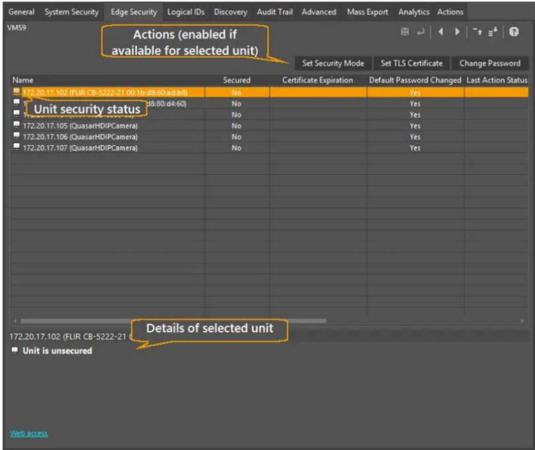

Note: Changing Edge Device Security Settings depends on the unit's inbuilt capabilities and on the method that was used to discover the unit.
Security Mode and Certificate changes can only be made on units that are covered by the FLIR Core Products plug-in, or were discovered as ONVIF units having the necessary ONVIF profile to support these actions.
For all other listed devices, the Set Security Mode, and Generate Self-Signed Certificate options are disabled (greyed-out).
Similarly, the Change Password option is only enabled for units that support password changes.
The following table displays device security status icons:
| Icon | Description |
| Unit connection is secured, but does not have trusted certificate | |
| Unit is fully secured (Secured connection and trusted certificate) | |
| Unit has security warning (see list below) | |
| Unit is unsecured | |
 | Unit is blocked |
| [S220] | Unit is inaccessible |
- The device name
- Whether the device connection to the archiver is secured or not
- If secured, the expiration date of its certificate
- Whether or not its password has been set by the user or is still set at the factory default
Note: Units discovered using the ONVIF plugin display Unknown as the plugin does not provide a method that can determine if a 'new' password has been used or if the user entered a value that corresponds to the manufacturer's default password.
- The status of the last action initiated for that device
When a device in the table is selected, any applicable security alerts for the selected device are displayed, and the available changes to security status are enabled.
Security Actions
The following Security Actions display above the table:
Set Security Mode
Set TLS Certificate
Change Password
- Set Security Mode
- Set TLS Certificate
- Change Password
Notes:
- Each of these Security actions can be applied to one or more entries in the table. The actions are only enabled if they are available for the device or devices selected. i.e. If more than one entry in the table is selected, only actions that are available for all selected devices will be enabled.
- When the user has Quasar Gen II and/or IOI-HD units, the following warning message displays: Warning. After Firmware upgrade, camera certificate must be reloaded.
- When using Change Password on PTZ Cameras:

The Change Password functionality interrupts an open PTZ session, and can affect PTZ functionality.
Admin Center operators can change password on PTZ cameras.
Follow these steps:
- Go to Edge Security page, and change the password.
- Go to the Camera/PTZ Configuration page (shown here), and carefully note which PTZ Driver is in use for the camera (circled).
- Disable PTZ Configuration (deselect), and save the change
- Re-enable PTZ functionality (select), using the driver that was in use (Choose from the drop-down menu), and save the change (回)

3 Licensing your VMS
You can view license details, including real-time usage details, in the AdminCenter.
Follow these steps:
- Go to the AdminCenter.
- On the Sidebar, click System Settings.
- In the System Settings Navigation window, select License.
If the FLIR United VMS Latitude Admin Center is opened on a system for which a license has not yet been installed, you must apply a license file. When your system was purchased, you were sent an email with an activation key, and a link to the Customer Portal. There, the user establishes a username and password, and can download the Activation Key associated with the purchased product. The Install License window opened by the Login process leads the user through the steps required to install the license.

The user should keep the invitation and the credentials generated for the Customer Portal - this information may be needed again if a license upgrade is required.
Licensing for large systems is usually completed by the Integrator during installation. However when a user wishes to upgrade the system capabilities, for example by adding more video channels, or using an add-in capability, a new license may be required.
Full details of the Licensing process are given in the Licensing User Guide document which can be found on the Documentation Web page.
Note: For an overview of Licensing a system, see below.
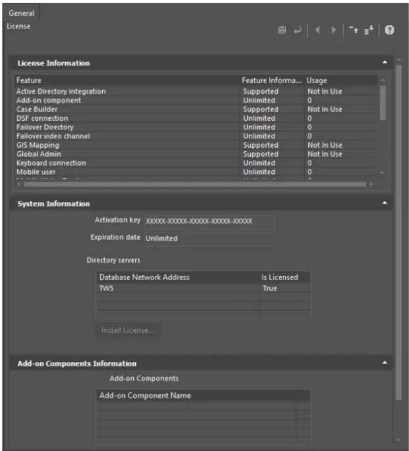
Figure 9 Licensing Tab

Your Activation Key is displayed in this view - keep it confidential!
License Information
This lists all possible licensed components and features.
Feature Information column For each entry, this shows the feature as Not Supported, Supported, Unlimited, or shows the maximum allowed number of licensed instances.
Usage column shows the current status for the component/feature ('Not in use', or the number of instances currently in use).
| Feature | Comment |
| Active Directory integration | Enables the option to integrate with Microsoft Active Directory - Supported / Not supported |
| Add-on component | Number of permitted Add-On components -- Add-On component licenses will be provided by TELEDYNE FLIR with the purchase ofengineering service integration modules |
| Case Builder | Enables the use of the Case Builder application - Supported / Not supported |
| DSF connection | The Direct Show Filter connection - Supported / Not supported |
| Failover Directory | The number of failover directory servers in the system, not including the primary directory |
| Failover video channel | Number of supported camera scenes or analog monitor scenes for which the Archiver failover mechanism is licensed |
| GIS Mapping | The GIS Mapping feature - Supported / Not supported |
| Global user | Number of global user connection licenses |
| Keyboard connection | Number of CCTV Keyboards concurrently configured in the system |
| Mobile User | Number of Mobile Users Licensed/Active |
| Mobile Video Feed | Number of Mobile Feeds Licensed/Active |
| Privacy Masking | Supported / Not supported |
| Recorder | Number of supported Recorders |
| Redundant Channel | Number of supported camera scenes or analog monitor scenes |
| Reporting Tool | Licensed to use Pre-defined Reports - Supported / Not supported |
| SceneTracker Channel | Number of SceneTracker user connection licenses |
| SDK connection | Number of logins to the Directory server from SDK applications |
| SNMP | Enables the administrator to send out SNMP traps to any 3rd party Network Management System and to configure which Latitude events will be sent out as traps - Supported / Not supported |
| User session | Number of concurrently active user sessions logged in to the Directory server |
| Video channel | Number of supported camera scenes or analog monitor scenes |
| Virtual video channel | Number of supported matrix outputs |
| Web Client user | Number of concurrently active Web Client sessions logged in to the Directory server |
System Information
This section shows the Activation Key in use and its Expiration Date, and shows the current server components with their license status.
Selecting a server in the table enables the Install License button, which allows the user to add or change licenses, or install licenses on additional servers.
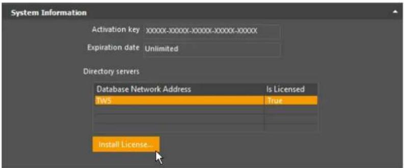
Figure 10 System Information Window
Licensing a system
The Licensing process is normally completed with your representative.
Below is a brief overview of the process.
Getting to the Install License window
The first time you log on (to an unlicensed system), the system opens the System Settings/Licensing page, and opens the Install License window.
If the system is already licensed and you wish to change the license or add a device to the license list, then go to the Systems Settings/License screen, select the device which you wish to license, and click Install License.
This opens the Install license window.
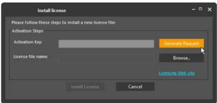
Figure 11 Install License Window
Get an Activation Key
You need an Activation Key to install a license.
This may be
• Provided by your representative,
OR
- You (or your integrator) are invited to register on the Client Portal, to get your keys on the FLIR License Management Portal (https://licensing.flir.com)
1

The invitation is one-time. Keep a record of the username and password used when you register, so that you can access the site again in the future if needed.
- Navigate to the FLIR License Management Portal and log in with your username and password.
A table opens displaying your Activation Key/s.
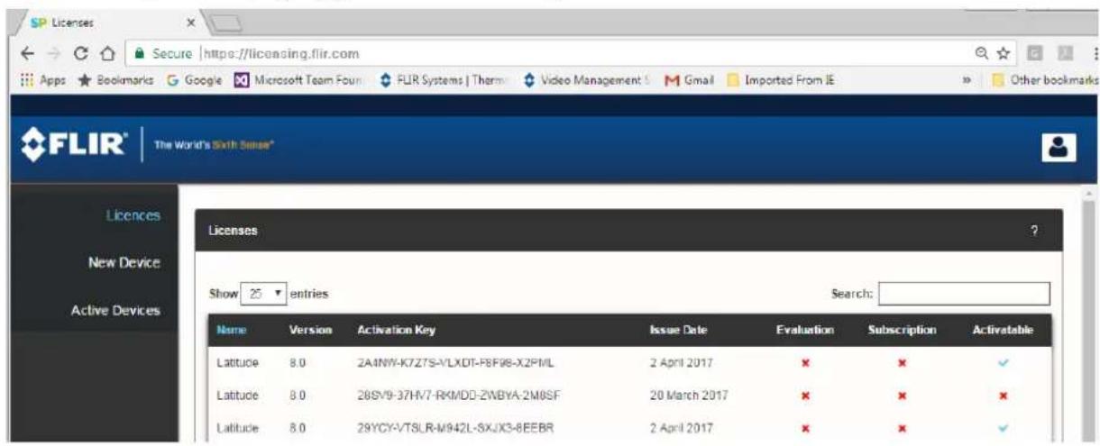
Figure 12 Licensing Client Portal
- Select the Activation Key to be used and copy to Clipboard.
To Generate a License
- Paste the Activation Key to the Install License window, and click Generate Request.
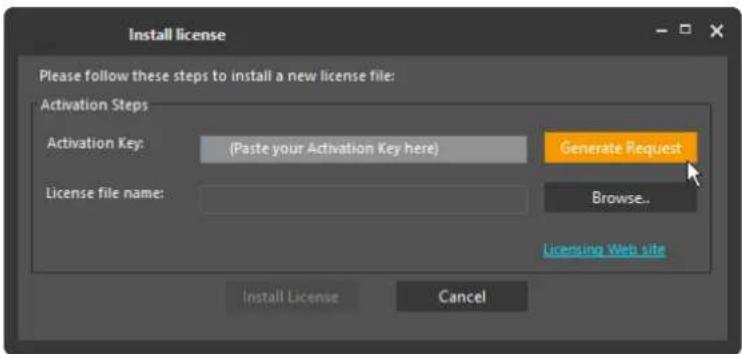
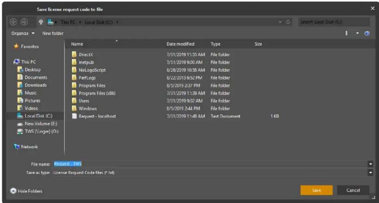
A 'request.txt' file is generated.
+--
- Save the Request file on your system.
Activating the License File using the Client Portal
- Go back to the Customer Portal window, and click New Device.
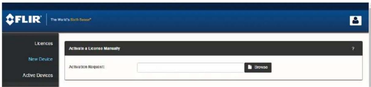
- Click Browse to navigate to request file that was saved, and click Activate. A license is generated and the screen displays a Download License Button.
- Save the file using the Save File dialog, and return to the Install License screen.
- Browse to the saved License file, and click the Install License option.
Details for Licensing additional Servers or installing a new License are given in the AdminCenter Help file.
4 Using the Quick Configuration Wizard (QCW)
The Quick Configuration Wizard (QCW) guides you through setting up the basic system to enable video monitoring and recording. Wherever possible, defaults are preselected to suit the needs of a standard installation, so the new user has only to enter data for variables particular to their installation.
Notes on Security
Latitude now includes facilities to increase system security by setting policies relating to communications rules between the system and its edge devices and web client connections. Edge devices passwords can hbe updated so that their manufacturer default passwords are no longer in force.
The Security for your FLIR United VMS Latitude System section provides a description of the facilities available.

Deciding on security policies and implementing them requires in-depth knowledge of the alternatives. Depending on your configuration and your requirements, some steps may be required before discovering edge devices, and some can only be implemented after the configuration is set up. Users are urged to discuss these with their TELEDYNE FLI support representatives when setting up their systems or making changes to the configurations.
4.1 QCW – Prerequisites
The QCW prerequisites are as follows:
- Archiver Configuration: The storage location of the Archiver/s must be correctly formatted before starting the Quick Configuration Wizard. The storage location must be formatted by setting the block size of the storage drive to 64K, and indexing must be disabled.
- Setting Network Addresses for Edge Devices: Before beginning the system configuration, make sure that all your encoders, decoders, and IP cameras are assigned addresses consistent with at least one of the networks on which your Archivers reside. Consult the technical documentation of the units for information on how to assign IP addresses to them.
Note: The automated Discovery processes does not discover edge devices (cameras, encoders, etc.) that are on networks different from those to which the Archiver/s are connected. Any such edge devices must be discovered using the Manual Discovery steps.
4.2 Starting the QCW
The wizard is opened after installing the license. If the wizard is not already open, it can be accessed from the Latitude Admin Center Dashboard screen by selecting Wizards/Quick Configuration Wizard/System.
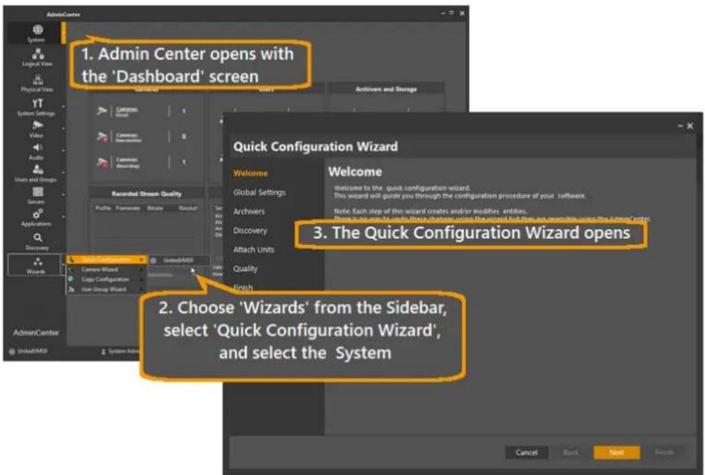
Figure 13 – Opening the Quick Configuration Wizard
The Welcome screen shows the steps to follow as you go through the Global Configuration Wizard:
- Global Settings – set the system defaults
- Archivers - define the Archiver/s and the Network/s to which they are attached
- Discovery – find Edge Devices on the specified Network/s
- Attach Units – associate the Edge Devices with Archiver/s
- Quality – set the parameters for video encoding
Click Next to open the Global Settings Screen.
4.3 QCW - Global Settings
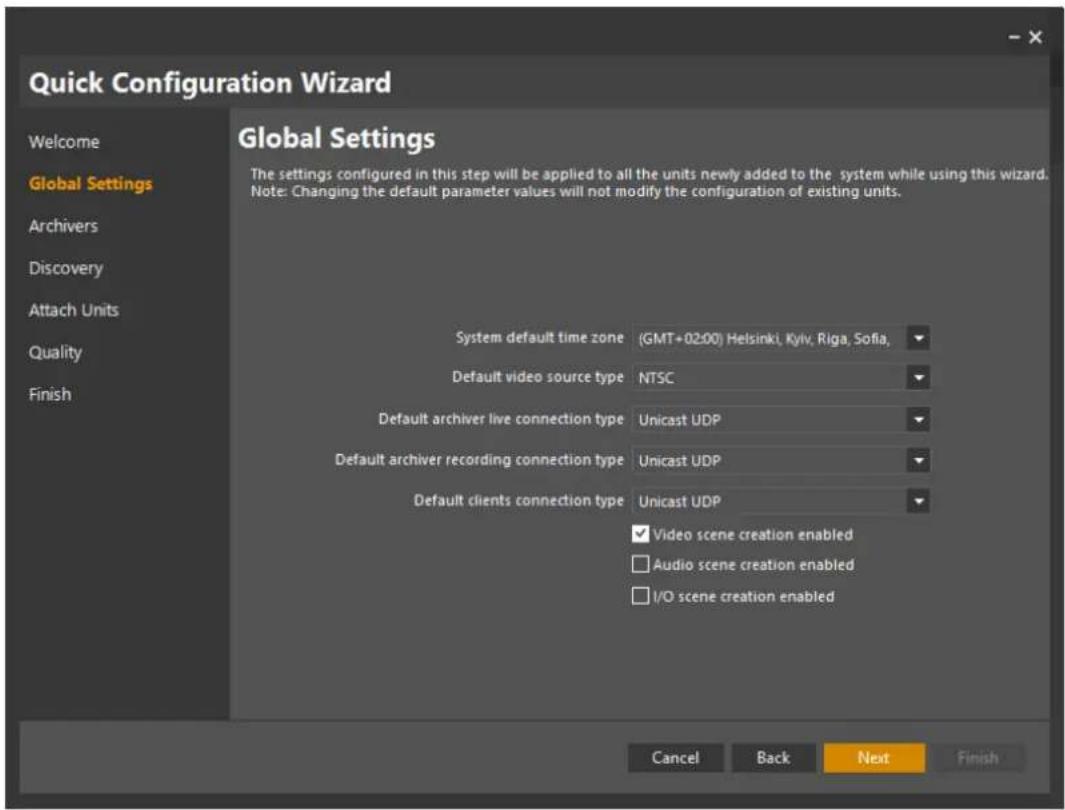
Figure 14 - Quick Configuration Wizard - Global Settings Screen
The Global Settings fields are set to the most commonly-used defaults. You will only need to change them if your site has some exceptional conditions.
Table - Quick Configuration Wizard - Global Settings - Defaults and available options
| Field | Default | Other Possible Values |
| Default NTP Server - Check-boxAddress field | UncheckedBlank | Optional - if you want to use an NTP Server, check the box and enter the NTP Server's network address. |
| System default time zone | Current Windows settings | Choose from drop-down |
| Default video source type | NTSC | PAL |
| Default archiver live connection type | Best available | Unicast, Multicast |
| Default archiver recording connection type | Best available | Unicast, Multicast |
| Default client connection type | Best available | Unicast, Multicast |
| Video scene creation enabled (check-box) | Checked | |
| Audio scene creation enabled (check-box) | Unchecked | |
| I/O scene creation enabled (check-box) | Unchecked |
- Update any defaults if required.
For example, if you want to use audio and I/O capabilities, the relevant options must be selected.
- Click Next to open the Archivers Screen.
4.4 QCW – Archivers
A table showing Archivers defined in the system displays:
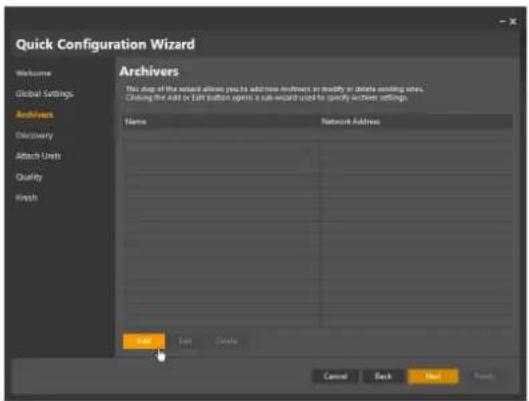
Figure 15 - Quick Configuration Wizard - Archiver List
- The first time you use the Wizard, the list will be empty - click Add to create a new Archiver.
The Archiver/General screen opens.
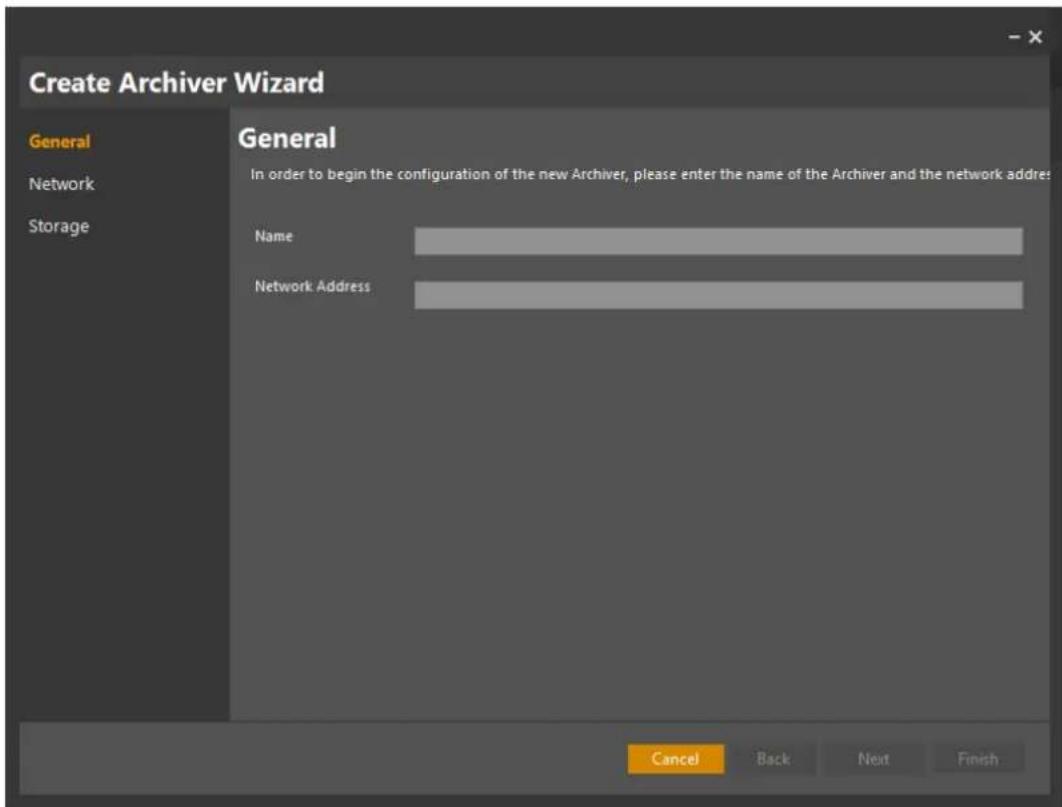
Figure 16 - Quick Configuration Wizard - Archiver Name, Network address
- Enter the name of the Archiver in the Name field, and the host name or IP address of the computer on which the Archiver resides in the Network Address field. This can be Hostname or the machine's IP address.
Note: The Archiver Server application must be installed on the target machine before adding it to the configuration. Refer to the Latitude Release Notes for more information.
- Click Next to open the Network screen.
4.5 QCW – Adding a Network
- The Network Screen of the Create Archiver wizard appears. If you are starting a new installation, the list will be empty.
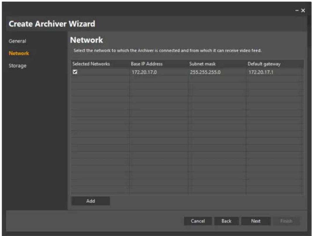
Figure 17 - Admin Center - Network List
- Click Add to add the network/s to which the Edge Devices are connected.
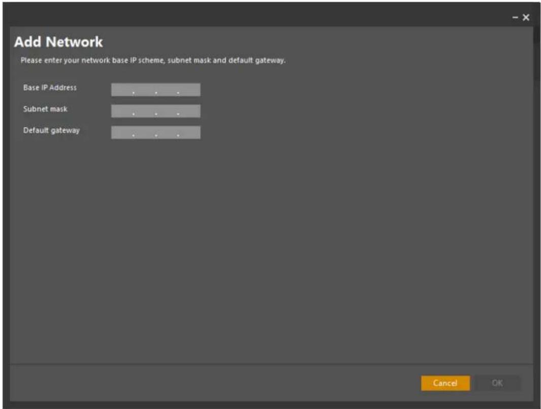
Figure 18 - AdminCenter - Add Network Screen
- Enter the details of the Network you are adding.
Table – Quick Configuration Wizard – Add Network Details
| Field | Value |
| Base IP Address | e.g. 192.168.2.0 |
| Subnet mask | 255.255.255.0 |
| Default gateway | (Optional) |
-
Click OK. You will return to the previous network screen, and the details that were added will now be shown, together with any other networks that may have been previously defined.
-
To add another network, click Add.
(This will return you to step 2 above.)
- When you have added and selected all the required networks, click Next.
4.6 QCW - Configuring Archiver Storage
The Storage dialog box appears.
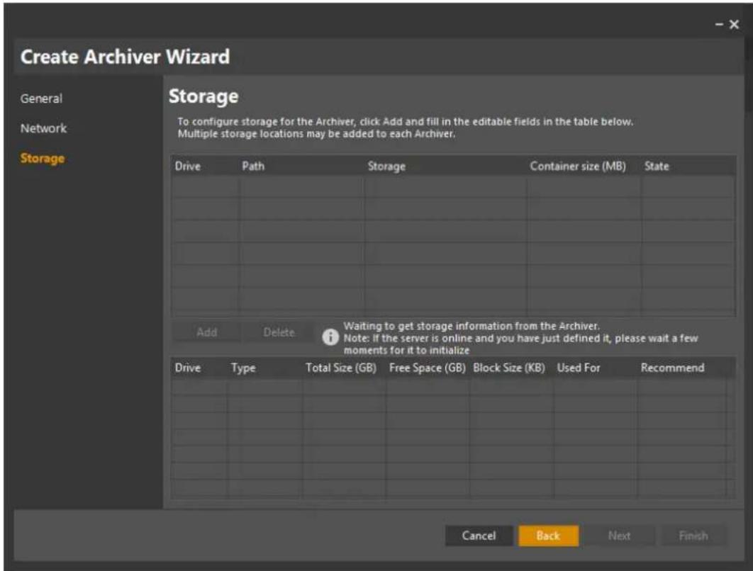
Figure 19 – Quick Configuration Wizard – Archiver Storage Definition – Waiting
The Waiting message shows that the system is still looking for Storage information, and the list of available storage is empty.
As soon as the Storage has been found, the message disappears, and a list of the available drives on the Archivers that were specified in Step 1 above is shown.
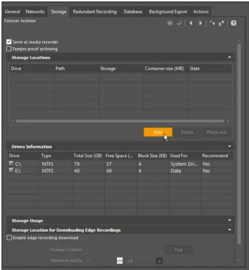
Figure 20 - Quick Configuration Wizard - Add Storage
- Click Add, and the Storage table will show a drop-down in the Drive column, where you can select which drive on the Archiver you wish to use as storage.
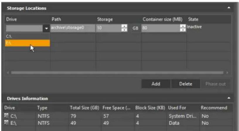
Figure 21 - Quick Configuration Wizard - Adding Storage Locations
- Use the Storage drop-down to allocate storage space on the drive (typically 1000 GB).
- Recommended Container Size is 80MB.
Notes: If the parameters you use are less than the minimum recommended Storage configuration, a warning message is displayed, giving you the opportunity to go back and
change the parameters.
Other parameters may also not meet the recommendations of the system (e.g. Formatted block size of the target drive, attempt to Configure storage on the C drive, etc), and such conditions will be listed so that the Administrators can take appropriate action.
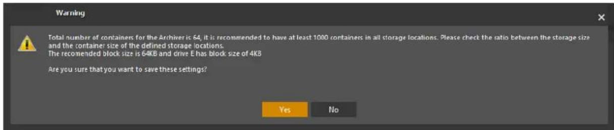
This process can be repeated, to define multiple storage locations.
- From the Quick Configuration Wizard Archivers screen, click Next to open the Discovery Screen
4.7 QCW – Discovery
The Quick Configuration Wizard Discovery screen is shown.
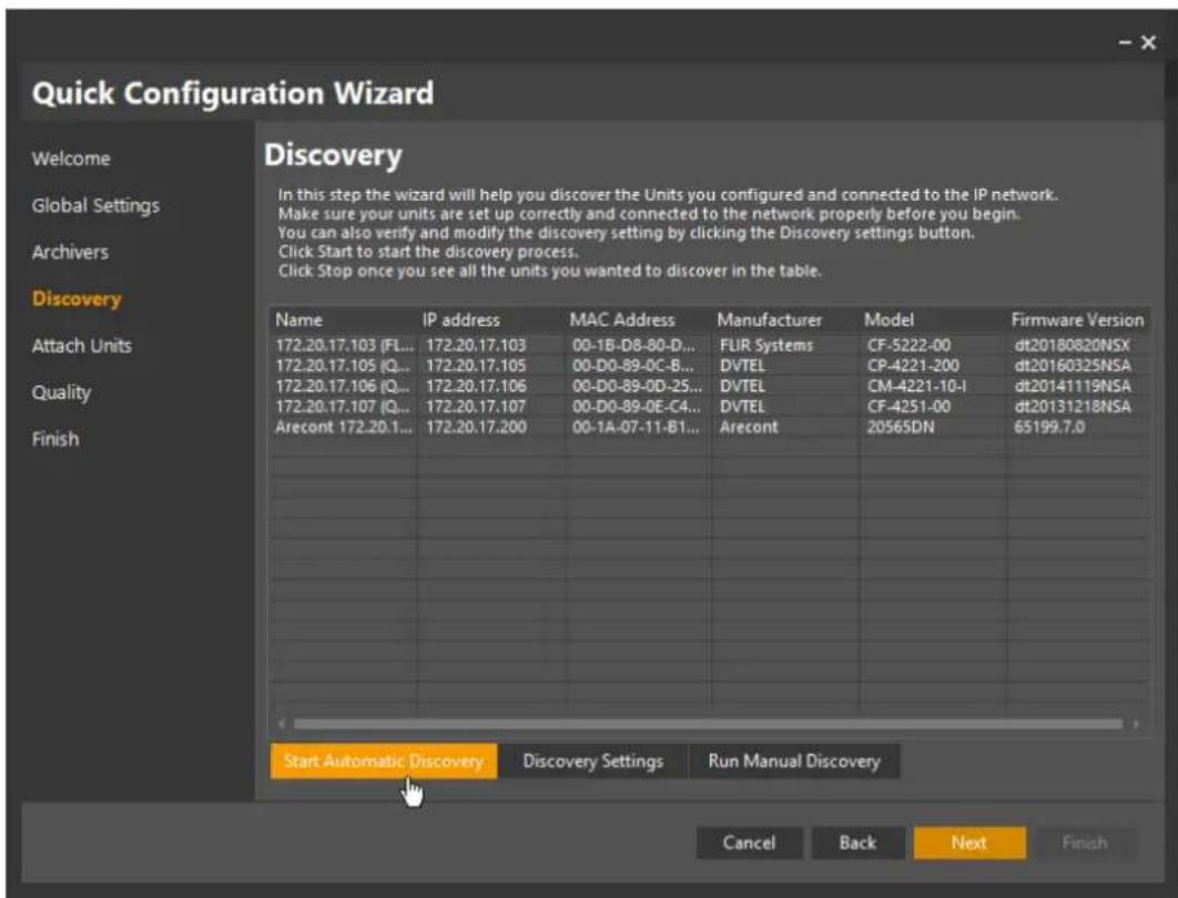
Figure 22 - Quick Configuration Wizard - Discovery Screen
If the units you need to discover are on the same network as the Archiver then the Automatic discovery can be used.
Clicking Start Automatic Discovery on this first screen runs the discovery process for all defined Archivers, on all their attached Networks, using the stored Discovery Settings.

NOTE: Running the Discovery feature may take several minutes.
One way to reduce time is to click on Discovery Settings, scroll through the list of proprietary cameras and units, and uncheck any type/s you do not want included.
Automatic and Manual Discovery
For most uses, the Latitude Automatic Discovery process is the normal way to discover and attach cameras for an installation. The first page of the Discovery process looks at all cameras attached to the Archiver or Archivers that have been defined, and on all networks defined as being attached to those archivers.
The parameters for the automatic process are stored as a set of Discovery Settings. These settings allow you to discover any cameras on the network that fit the list of possible suppliers and models. Initially, these are the camera manufacturers' default settings. If necessary, users can click the Discovery Settings button and make changes to the stored settings, and the new values are then used for any subsequent automatic discovery processes.
This si covered in more detail in the sections on Discovery Settings below.
Alternatively, the Manual Discovery process discovers individual cameras, based on their Network Address, manufacturer and model information. (The Manufacturer and Model information allows the system to use the appropriate driver information needed to communicate with that particular camera (the 'plug-un')\
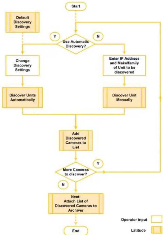
If required, these processes can be run multiple times, to build up a complete list of discovered cameras. Latitude then allows you to add the discovered cameras to their Archiver.
The process is described below.
Single boxes are actions done by the operator. Boxes with double lines are actions carried out by Latitude.
flowchart
graph TD
    A["Start"] --> B{Use Automatic Discovery?}
    B -->|Y| C["Default Discovery Settings"]
    B -->|N| D["Enter IP Address and Make/family of Unit to be discovered"]
    C --> E["Change Discovery Settings"]
    D --> F["Discover Unit Manually"]
    E --> G["Discover Units Automatically"]
    F --> H["Discover Unit Manually"]
    G --> I["Add Discovered Cameras to List"]
    H --> I
    I --> J{More Cameras to discover?}
    J -->|Y| K["Next: Attach List of Discovered Cameras to Archiver"]
    J -->|N| L["End"]
    K --> M["Operator input"]
    K --> N["Latitude"]
Figure 23 - QCW - Automatic and Manual Camera Discovery
4.7.1 Automatic Discovery
Use this method when the units to be discovered are on the same network as the Archiver.
The default Discovery Settings include a set of 'plug-ins' which cover all proprietary entities that Latitude has pre-defined. If required, these settings can be changed by clicking on Discovery Settings. The Discovery Settings screen will appear.
Note: The Discovery Settings are only used by the Automatic Discovery process, and not by the Manual Discovery process.
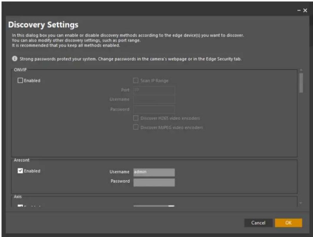
Figure 24 - Discovery Settings screen
Proprietary Discovery, Latitude initially sets the parameters for each manufacturer and product category corresponding to the manufacturer's default settings.
- If you have changed the manufacturer's settings (such as Username and Password defaults) in some or all of the entities to be discovered, then change the settings in the relevant groups. Then click OK. This will return you to the Quick Configuration Wizard - Discovery Screen.
There are additional facilities in support of the FLIR family of products which simplify the discovery process - see Discovering FLIR cameras and encoders.

IThe Discovery process covers products that support multicast. Some devices, including FLIR Recorders, only support unicast, and therefore must be discovered manually.
-
Once you return to the Automatic Discovery screen, click Start Automatic Discovery. The system will add all the units it finds to the list on the Discovery screen. When you see all the units that need to be discovered, click Stop automatic Discovery to end the process.
-
The cameras that have been discovered are added to the list in the Discovery screen and process continues at 3.8 QCW - Attach Cameras to Archiver.
-
ONVIF Discovery -
If you want the discovery process to use only ONVIF information, check the Enabled check box in the ONVIF section. This will disable all the proprietary parameters.
4.7.1.1 Discovering FLIR cameras and Encoders
Scroll to FLIR section of the Discovery Settings screen.

Figure 25 – FLIR Camera Plugin Settings - Common Settings
The FLIR Plugin will use the stored discovery settings for all FLIR integrated products, without the user needing to set up the individual parameters for the different models. However, if needed, the user can access one of more particular model or model range, to make appropriate changes.
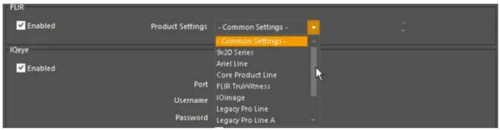
Figure 26 – FLIR Camera Plugin Settings - Model / Model Ranges
For each model or model range, the stored parameters are shown and can be updated if required. Common Settings cover the majority of cases, and if necessary, the user can select a particular model if some specific parameter in the stored settings needs to be changed.
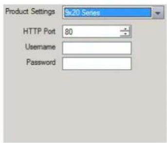
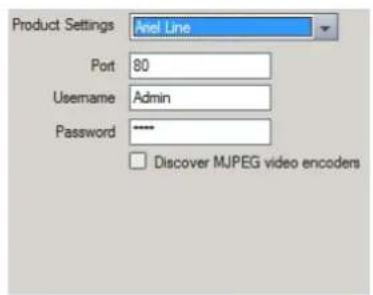
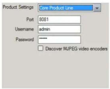
Figure 27 – FLIR Camera Plugin Settings - Examples of specific model parameters
4.7.2 Manual Discovery
Use this method when the units need to be discovered manually – for example, when they are on a different network from the Archiver.
- From the Quick Configuration Wizard - Discovery Screen, click Discover Unit Manually. The Add Unit manually screen will appear.
![Add Unit manually IP address 0 0 0 0 Host name Unit Type FLIR Product Type - Auto Detect - Username [Use default username] Password [Use default password] Discover H265 video encoders Strong passwords protect your system. Change passwords in the camera's webpage or in the Edge Security tab. OK Cancel](/content/2026/05/943976/images/5e22dfd6fc514afbb02cc85fa8ad44fe3364e95b8b051a1481a60cb968ce7ea3.jpg)
Figure 28 - QCW - Add Unit Manually screen
- Enter the IP address of the unit to be discovered.
- Use the Unit type drop-down to select the manufacturer/model family, and click OK.
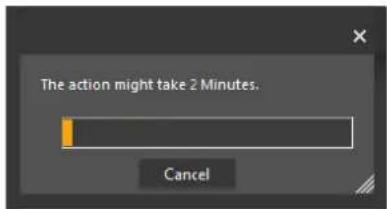
- A progress bar is shown while the system searches for the unit.
The system indicates when the unit has been found.
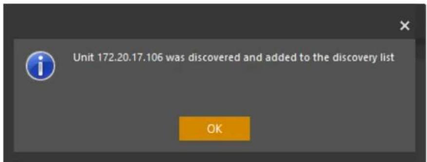
- Click OK. The Discovery Screen is shown, with the camera added to the list. The process continues at 3.8 QCW - Attach Cameras to Archiver.
4.7.3 Adding Generic Cameras
The Generic camera plug-in enables users to Configure edge devices which are not integrated into the FLIR VMS system and are not ONVIF Compliant. This plug-in supports any edge device which transmits a standard RTSP H.264 or MPEG4 stream, or alternatively MJPEG over HTTP.
Note: Using this plug-in, users are only able to view live and record the stream. Configuring video or picture settings from Latitude, using motion detection, PTZ and other features are not supported.
Configuration:
Discovering a camera via the Generic Camera Plug-in is done manually, in the 'Add unit manually' screen. You can access the screen using one of the following methods:
Add the Unit to an Archiver manually
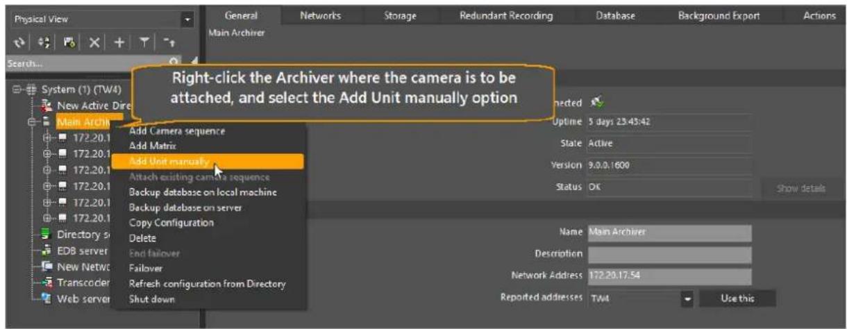
Figure 29 - Add Generic Unit Manually
OR
Discover a Unit manually from the Discovery page
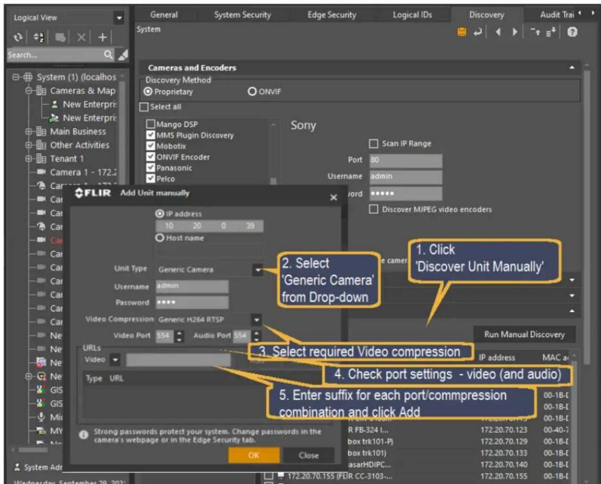
Figure 30 - Discover Unit Manually from Discovery page
The following steps are required:
-
Open the 'Add Unit manually' screen using one of the above methods.
-
Select 'Generic Camera' from drop-down.
-
Select required Video Compression from the drop-down.
-
Check settings for video port (and audio port if required)
-
Enter the appropriate suffix information for the device as specified by the supplier, and click 'Add'.
-
Repeat for each required stream.
For each stream, the full Unit/Port/URL suffix are displayed in the table.
This is updated if the user changes the IP address Compression method or URL suffix.
4.8 QCW - Attach Cameras to Archiver
After the Discovery process, the Quick Configuration Wizard lists all the Edge Devices that have been discovered.
Click Next to attach the cameras to the Archiver/s

NOTE: If there is more than one Archiver in the system, and some discovered cameras have not been attached to the previous Archiver, then you will have the option of attaching remaining available cameras to the second/subsequent Archiver/s.
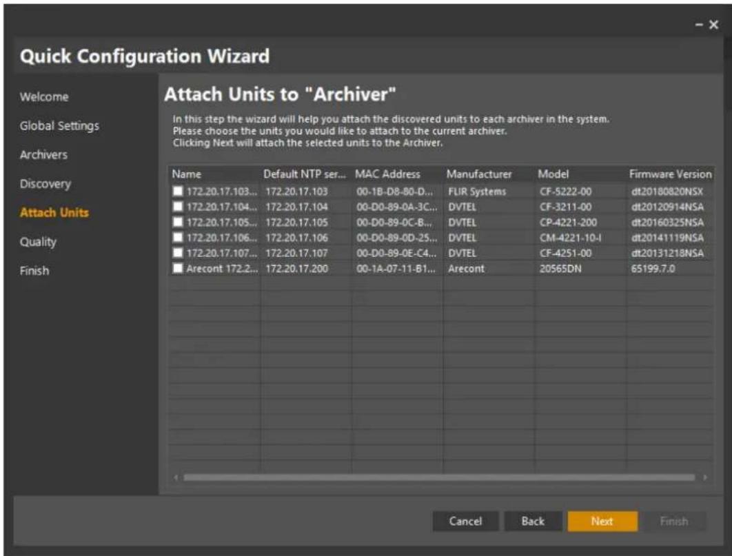
Figure 31 - Quick Configuration Wizard Discovery screen showing Discovered list
- Use the check boxes on the left to select which units are to be attached to the archiver.
- If you have more than one Archiver, the wizard will start with the newest Archiver, and when you have finished and click Next, it will repeat with the second Archiver, and so on.
- When you have attached all the required cameras, click Next to open the Quality Screen.
4.9 QCW – Quality
The Quality screen lists all cameras that were 'Attached' in the previous step.
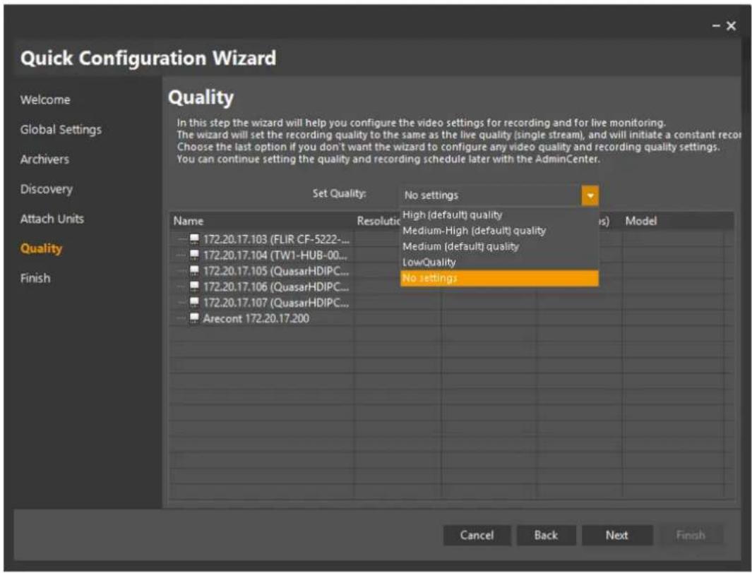
Figure 32 - Quick Configuration Wizard - Quality Settings
- Use the drop-down to set a 'quality' level for the cameras that were attached.
Note: In the example shown, the setting 'Medium (default) quality' was used – all cameras in the list will be set to their default settings that correspond to the selected value.
-
You can choose to change settings later through the Camera screen. You can also use the Copy Configuration Wizard to copy the configuration to other cameras.
-
When you have selected the Quality setting you wish to apply, click on Next to complete the process.
The Quick Configuration Finish screen will be shown.
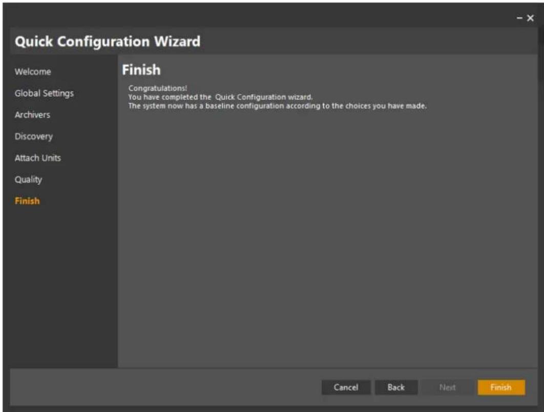
- Click on Finish to close the wizard.

NOTE: If you selected a quality setting and applied it to the phones that you attached to the archiver/s, then recording will start when you click on Finish.
You can choose to change settings later through the Camera screen.
You can also use the Copy Configuration Wizard to copy a configuration to multiple other cameras.
Your initial set of cameras will be connected to the Latitude System, and recording will start now. You can use the system!
4.10 Accessing Applications from the Sidebar
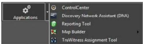
This button allows you to launch various Applications.
| Application | Notes |
| ControlCenter | The client application used by the operators who monitor the live video material, handling the alarms raised by the system, finding and viewing video clips of previous incidents, and preparing materialfor export from the system.Note:Launching the Control Center from the Sidebar will use the same credentials that were used to launch the Admin Center. |
| Discovery Network Assistant (DNA) | Full set of Edge Device tools for setup and configuration of FLIR Edge Device IP addresses, Security/Credential settings, Video mode and Firmware updates. |
| Reporting Tool | An application that provides reports on Latitude events by querying the audit databases maintained by the Latitude EDB servers (e.g. reports on User Logon , Entity Configuration , Incident , Alarm , Equipment Failure , and Server Monitoring) |
| MapBuilder | An application that allows the creation of full-featured security maps. Camera Icons can be placed on schematic maps or on aerial photographs. |
| TruWITNESS Assignment Tool | For users of TruWITNESS Situational Awareness facilities, this tool runs the application that assigns/reassigns TruWITNESS appliances to users. |
4.11 Accessing Wizards from the Sidebar
This button gives access to the Latitude Wizards.
| Application | Notes |
| Quick Configuration | Takes the user through the steps of setting up the Latitude system for the first time - defining global settings, location and configuring key servers, as well as discovering, adding and configuring units. Described in detail in 3 Using the Quick Configuration Wizard (QCW). |
| Camera Wizard | A wizard that takes the user through the steps of adding and configuring units and configuring the camera settings, recordings and events. |
| Copy Configuration | A dialog for selecting and copying key configuration between similar units and entities. Described in 4.2.1 - Using ‘Copy Configuration’ |
| User Group Wizard | A wizard that takes administrative user through the steps of creating custom User Groups, assigning privileges and rights to the group, and selecting ussers to belong to the group. |
5 Setting up Cameras in the Latitude System
During the initial setup phase, once cameras are attached and the system has applied their default parameters, you may wish to make specific changes to some of the settings. You'll normally only enter information that is unique to a particular camera (such as its name and description), and possibly adjust the picture settings to suit the camera's position and surroundings.
This section describes the Camera settings screens, and covers the areas where you may typically want to make changes.

NOTE: The Admin Center allows the user to make detailed changes to all parameters controlling each camera. In this Guide, only the more-often accessed parameters are covered. For detailed information about all settings see the FLIR United VMS Latitude Help file.
You can set up one device and use 'Copy Configuration' to copy all or some of its settings to other devices.
Click the Help symbol from any screen. The Help system provides detailed information on the contents of all fields.
5.1 Individual Camera Settings – the Camera Parameter Screens
The Camera screen allows you to select a particular camera (from the Logical, Physical or Video views), display all its parameters, and change them where necessary.
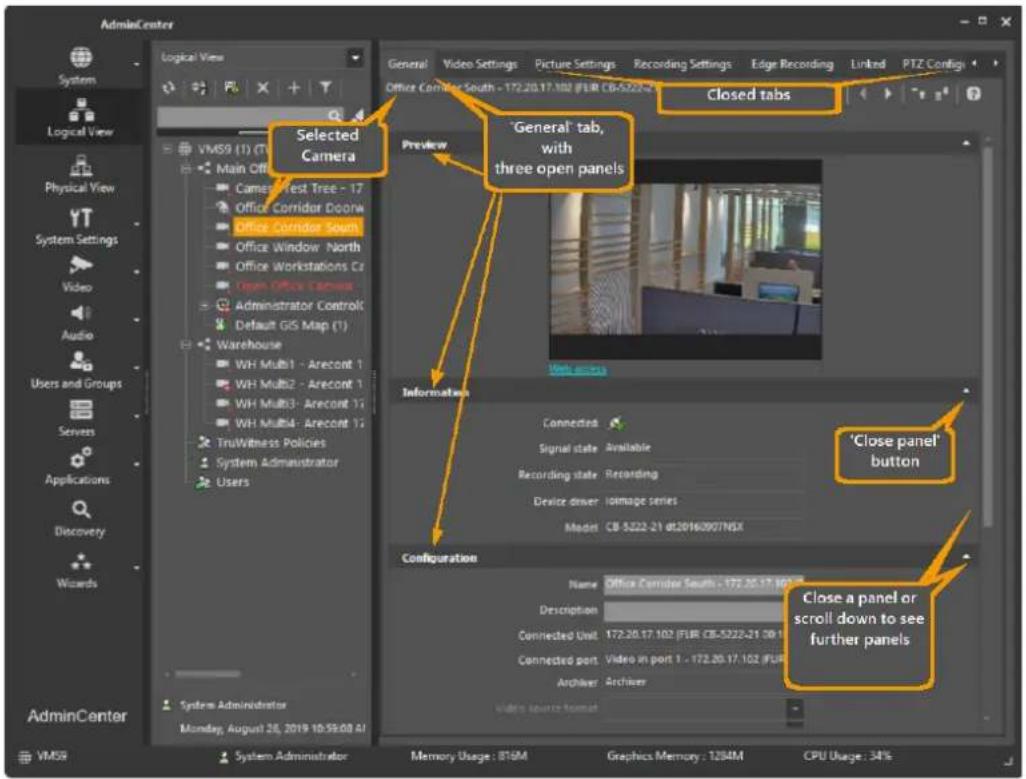
Figure 33 - Admin Center - Camera Parameter Screen
The screen is organized multiple tabs, each with Panels that can be opened or closed.
At any time, only one tab can be open. Within the open tab, you can open (maximize) or close ('minimize') any of the panels.
General Tab
Video Settings Tab
Picture Settings Tab
Recording Settings Tab
Linked Tab
PTZ Tab
PTZ Controls
Motion Detection Tab
Privacy Masking Tab
Actions Tab
5.1.1 General Tab
In the General tab the user can name the camera, set up its connection type and its retention settings.
Note on Coverages and Profiles
The Camera settings described in the next three sections (Video Settings Tab, Picture Settings Tab and Recording Settings Tab) are all defined in terms of coverages (time periods) during which Profiles (sets of rules) are enforced.
In each of these three tabs, default parameters are set and access to them is disabled (grayed out) unless you set a Coverage.
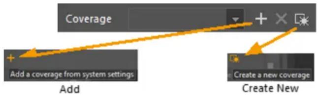
To set a new coverage:
- From the Coverage field, click on one of the available options:
- Add
■ Create New
5.1.2 Video Settings Tab
The Video Settings tab enables the user to set up the camera video parameters.
The user must choose resolution, FPS, and compression quality.
The separate Live and Recording settings enable you to use different settings – for example, high resolution when viewing live for maximum clarity, and lower resolution for recording to save storage space. If the camera is set up in separate streams mode, the same settings must be set for the recorded stream.
The Advanced Panel provides an option to carry out additional settings.
To access Advanced Panel settings:
Set a Coverage in the General panel, and then select the Advanced settings options.
For more detail, see the online Help system.
5.1.3 Picture Settings Tab
The Picture Settings tab sets up picture parameters such as brightness, contrast etc. For more advanced settings, select the advanced option, and refer to the online help for information.
Note: These camera parameters are set up per camera, rather than using the system defaults.
5.1.4 Recording Settings Tab
This tab is used for schedule-based recording. It enables you to set when the camera records, and for how long the recording is maintained.
To set recording parameters:
- Add a coverage, and set the number of days you want to keep the video.
5.1.5 Linked Tab
The Linked tab enables you to associate devices (i.e. microphones and speakers) with the current camera.
(See 5.1 Setting up other Entities: Microphones and Speakers)
5.1.6 PTZ Tab
The PTZ tab provides you access to the camera Pan-Tilt-Zoom settings.
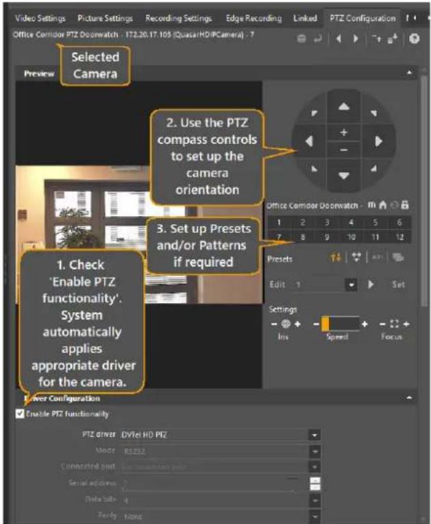
Figure 34 - Using the PTZ Tab

Latitude discovers the integrated IP PTZ camera default settings.
For other PTZ cameras, you must set up these parameters – consult the camera's documentation and the Latitude Help system.
- The PTZ compass window lets you move the camera to set up its home orientation, (and for each Preset or Pattern if required).
Presets To set up a Preset, select a preset number, use the compass to move to a desired location, click Edit and enter a name, and click Set.
When you have defined the Presets you need, click the Save Icon.
Patterns
5.1.6.1 PTZ Controls
The PTZ Controls let you access specific camera functions.
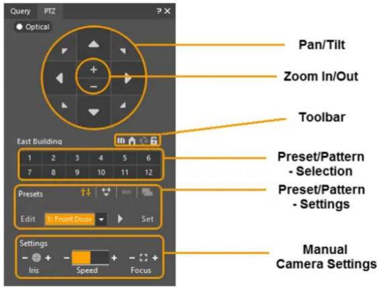
Table - PTZ Control Functions
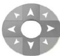
Pan/Tilt controls:
Click on an arrow to move the camera in the indicated direction.
Sensitivity is greater as you move further from the center
- clicking near the inside of the circle will move the camera in smaller steps
- clicking near the outside will move it in larger steps.

Zoom In/Out:
Click to single-step the required change. Click-and-hold for continuous change
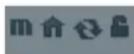
Toolbar:
Note: All toolbar facilities are limited to cameras that have these facilities integrated into the <%ADMINCENTERNAME%> system.
Click on the required symbol:
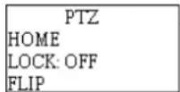
- Menu - Allows direct interaction with the camera's built-in menu. The menu is superimposed on the camera view in the Preview window. (See Built-in Menus)

- Home - clicking Home returns the camera to its Home position.

- Flip - Flips the image 180 degrees

- Lock - Disables the PTZ capability for other operators. (where supported) (This is a Toggle - clicking again re-enables)
Selection Number - Allows choice of a Preset or a Pattern (depending which mode has been selected (by clicking on the Preset icon or the Pattern icon).
The selected mode is shown to the left of the icons.

The current selected mode is shown (Preset or Pattern). Click on the required mode or on the AUX or SceneTracker icons.

Preset – Clicking on a selection number moves the camera to show the preset view associated with that button.

Pattern – Allows the operator to record a series of camera moves, which are stored as a 'Pattern'. This recorded path is followed whenever the Pattern is invoked.

Aux – For devices that work on the same principle as a PTZ camera.(e.g. mounted with a PT motor or servo). Allows one preset defined for each numbered load button.

Scene Tracker - When selected, works like a digital version of a pan, tilt and zoom preset within Scene Tracker views, remembering what viewed area of the composite Scene Tracker view was loaded when the preset was defined. Allows one preset defined for each numbered load button

The Edit controls allow Presets or Patterns to be set up, named and edited.
This area allows each preset to be named (Edit), and stored (Set). The pan tilt and zoom settings of the camera's current view will be stored.
Allows one preset defined for each numbered load button up to 12. (Up to 256 Presets can be defined. Presets after the first 16 are available accessible through the drop-down in the Edit field.
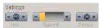
Allows direct adjustment of the camera's aperture and focus settings
5.1.7 Motion Detection Tab
Motion Detection refers to the system's ability to 'notice' movement. This gives two benefits:
- Recording when movement is detected: This allows you to save recording space, as no recording occurs until there is motion.
- Triggering events when motion is detected: Events such as activating alarms, changing camera resolution to show more detail occur when motion is detected.
Motion detection is normally set up using the capabilities of the cameras themselves (edge-device based).
The parameters for setting up basic edge-based motion detection are described below.
Note: The Latitude system also supports archiver-based motion detection – for more information on this and for more details about edge-based motion detection capabilities, see the Help system.
To set up Motion Detection for a camera, open the Camera/Motion Detection Tab.
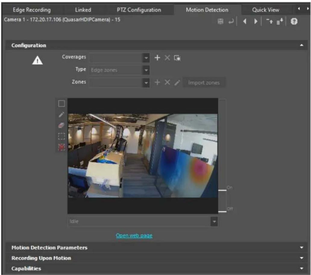
Figure 35 - Camera Screen - Motion Detection Tab
- Before configuring Motion Detection, check the capabilities of the camera in the Capabilities Panel.
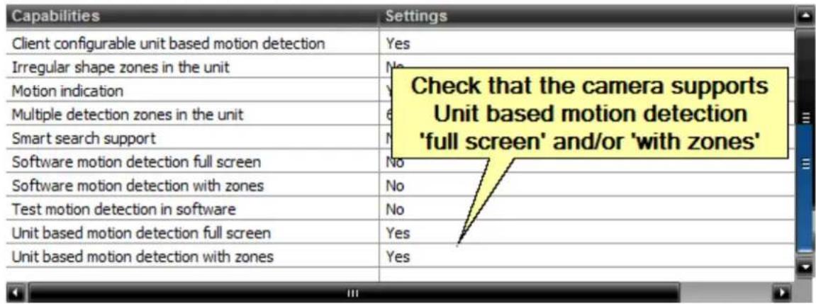
Figure 36 – Camera - Motion Detection Capabilities
- Once you have verified that the camera supports Motion Detection, go to the Motion Detection Tab / Configuration Panel
- All parameters are disabled until you set a Coverage during which Motion Detection is to be activated.
Choose an existing Coverage or define a new one. Use the same procedure as for defining coverages for camera settings.
The Zones drop-down indicates what MD modes are available with this camera. If you want to use Edge Zones, then select an existing zone, or use the following steps to define a new one.
- Click and enter a name for the zone. This enables the Preview/Zone definition display.

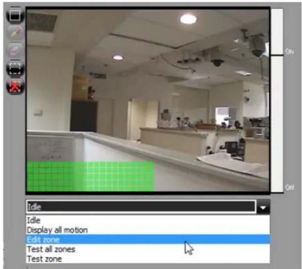
Figure 37 - Camera - Motion Detection - Preview/Zone Definition
1. Select Edit Zone from the drop-down to define a new MD zone.
2. A set of icons allows you to use the cursor to define the zone.
Icon | FunctionMark rectangle lets you define a zone by clicking and dragging a rectangle using the cursor. |
 | Mark All icon selects the whole field. |
 | Clear All icon clears the whole field. |
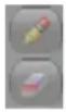 | Mark Individual and Erase Individual allow you to define irregular zones (only when supported by the camera – usually these icons will be disabled) |
- When you have marked the zone, you can select Test Zone in the drop-down to see whether the zone is set up satisfactorily.
As motion is sensed, it is indicated by the vertical bar on the right of the preview window. If motion exceeds the Motion On threshold, a red frame is shown around the preview window.
To reset and test again, select Idle in the drop-down, and then select Test Zone again.
- Motion Detection parameters
Note: Setting these parameters is a complex task – you may want to make a note of the default parameters before changing them
| Parameter | Description |
| Sensitivity | Overall sensitivity |
| Motion On Threshold | Proportion of motion to be regarded as ‘Motion On’ |
| Motion Off Threshold | Proportion of motion to be regarded as ‘Motion Off’ |
| Consecutive Frame Hit | Parameter that can be used to suppress low-duration events (such as random noise) |
Note: Depending on the particular camera model, some of these parameters may not be supported.
Record upon Motion parameters
The table below gives basic details about these parameters. Three typical combinations of settings are indicated. These are explained below.
Normal – use these choices to record only when motion is detected, with some automatic pre-event recording.
Advanced - As above, but when motion is sensed, switch to a higher resolution for the motion events, and then revert to normal resolution for live viewing
'Boost on record' – Record at low resolution, and use higher resolution for segments with motion.
| Parameter | Description | 1 | 2 | 3 |
| Bookmark motion on events | i.e. bookmark on the regular video of this camera | A | A | A |
| Record upon motion on | Always record when motion is sensed | A | A | A |
| Pre-event recording | Check to include a recording of the selected time before motion started.Note: System will automatically buffer this camera so that this can be done. Only enabled when Record upon motion is set. | A | A | A |
| Set recording video profile upon motion on | Allows selection of a different video profile when recording (normally higher than the profile used for live viewing) | i | A | A |
| Stop recording/restore profile | Set the time after which the profile used for recording can revert to the profile for regular viewing |
For more information, consult the Help file.
5.1.8 Privacy Masking Tab
The Privacy Masking tab enables you to set up mask areas that are not visible to Operators. (User Privileges may be set to allow some operators to deactivate Privacy Masking) For more information, consult the Help file.
5.1.9 Actions Tab
The Actions tab is used to select events related to this camera, and associate Actions with the Events.
The process of working with Actions and Events is described in more detail in the following sections:
• 8.1 Set Up Alarm Types
• 8.2 Set Up How Alarm is Triggered
System-Wide Events
Some events require similar actions, regardless of the entity from which they come. This means that you do not have to define the same event multiple times (for each entity that could cause it). The event is defined once, and the specified action will be carried out regardless of the origin. These are described in 10.12 System-Wide Events
5.2 Setting up Groups of Cameras
5.2.1 Using 'Copy Configuration'
Copy Configuration gives a quick way to copy all or part of the configuration parameters from one entity to others that you select.
The Copy Configuration tool can be opened by right-clicking on a camera (or other entity) in the Physical, Logical or Video views.
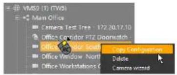
Copy Configuration can also be accessed as a Wizard by clicking on the Sidebar/Wizards button.
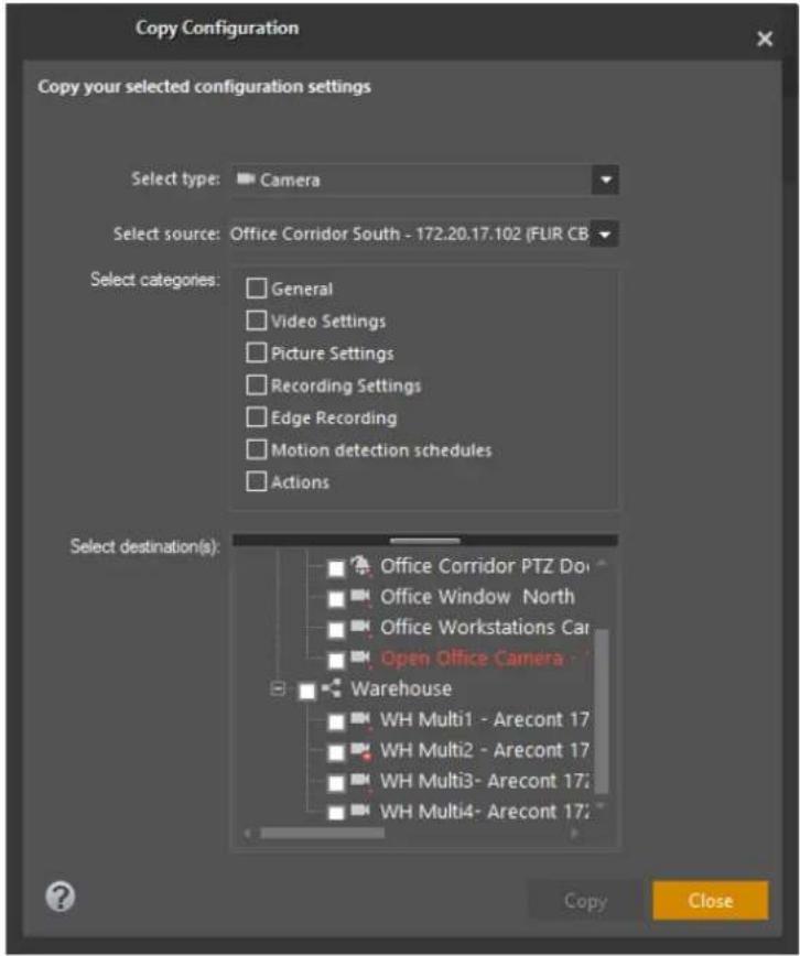
Figure 38 - Copy Configuration Tool Screen - Camera

IMPORTANT NOTE: You can only use Copy Configuration for entities that already defined in the system.
- Depending on what entity is selected in the Navigation tree, the appropriate Copy Configuration window opens.
The ‘Type’ and ‘Source’ fields are pre-set for the entity selected when the screen was called, and all possible targets – that is, all entities that are of the selected Type – display in the Destinations list.
The Categories check boxes enable you to select which group or groups of parameters you wish to copy to the target entity/s. The categories generally conform to the configuration tabs in the corresponding entity setup window, but exclude those settings which should always be individual.
- The Destinations list displays all entities that are of the same type as the one in the Source list, and whose characteristics in the selected 'Categories' can correspond.
For example, only destination cameras that support the resolution of the source camera are shown.
- By selecting the root entry option, all elements in the Destination list are selected.
Otherwise, select the individual elements you wish to reconfigure, and then click Copy to update all the selected entities.
6 Setting up other Entities
6.1 Microphones and Speakers
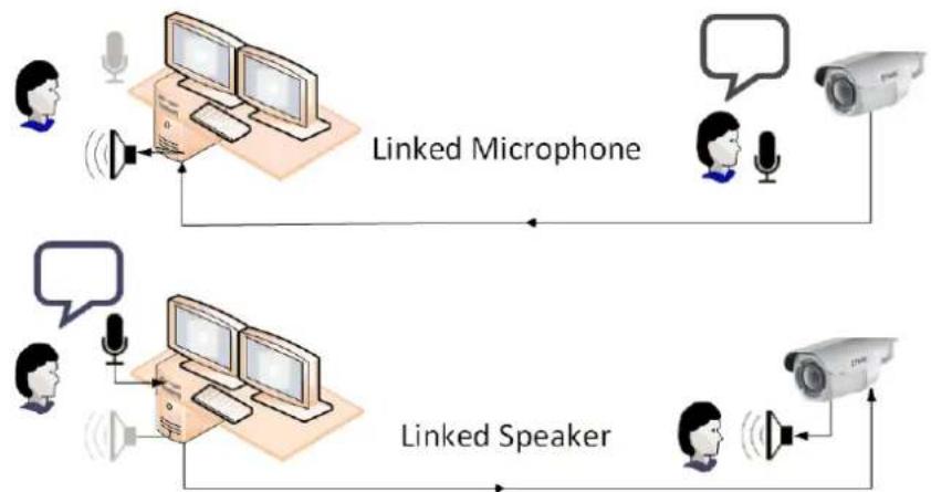
Latitude allows analog microphones and speakers to be attached using the dedicated connection points on edge devices (cameras and encoders).
flowchart
graph TD
    A["User"] --> B["Speaker"]
    B --> C["Linked Microphone"]
    C --> D["User"]
    D --> E["Camera"]
    E --> F["Speaker"]
    F --> G["Linked Speaker"]
    G --> H["User"]
6.1.1 Define a Microphone or Speaker
A linked Microphone allows sound to be played/recorded together with the video image from the camera to which it is linked.
Follow these steps:
- If a microphone or speaker was not created upon Discovery, you can go to the Physical View, and select the Edge Device to which it is to be attached.
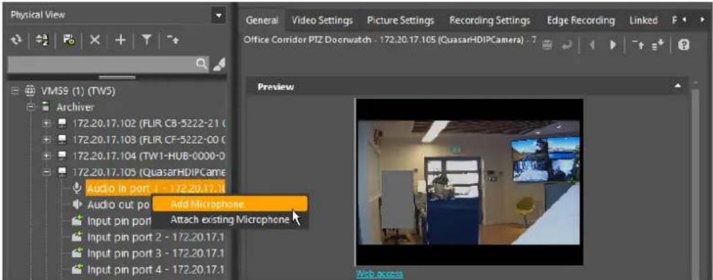
Figure 39 - Add Microphone to Audio In Port
2. Select Add Microphone or Add Speaker.
The appropriate screen displays.
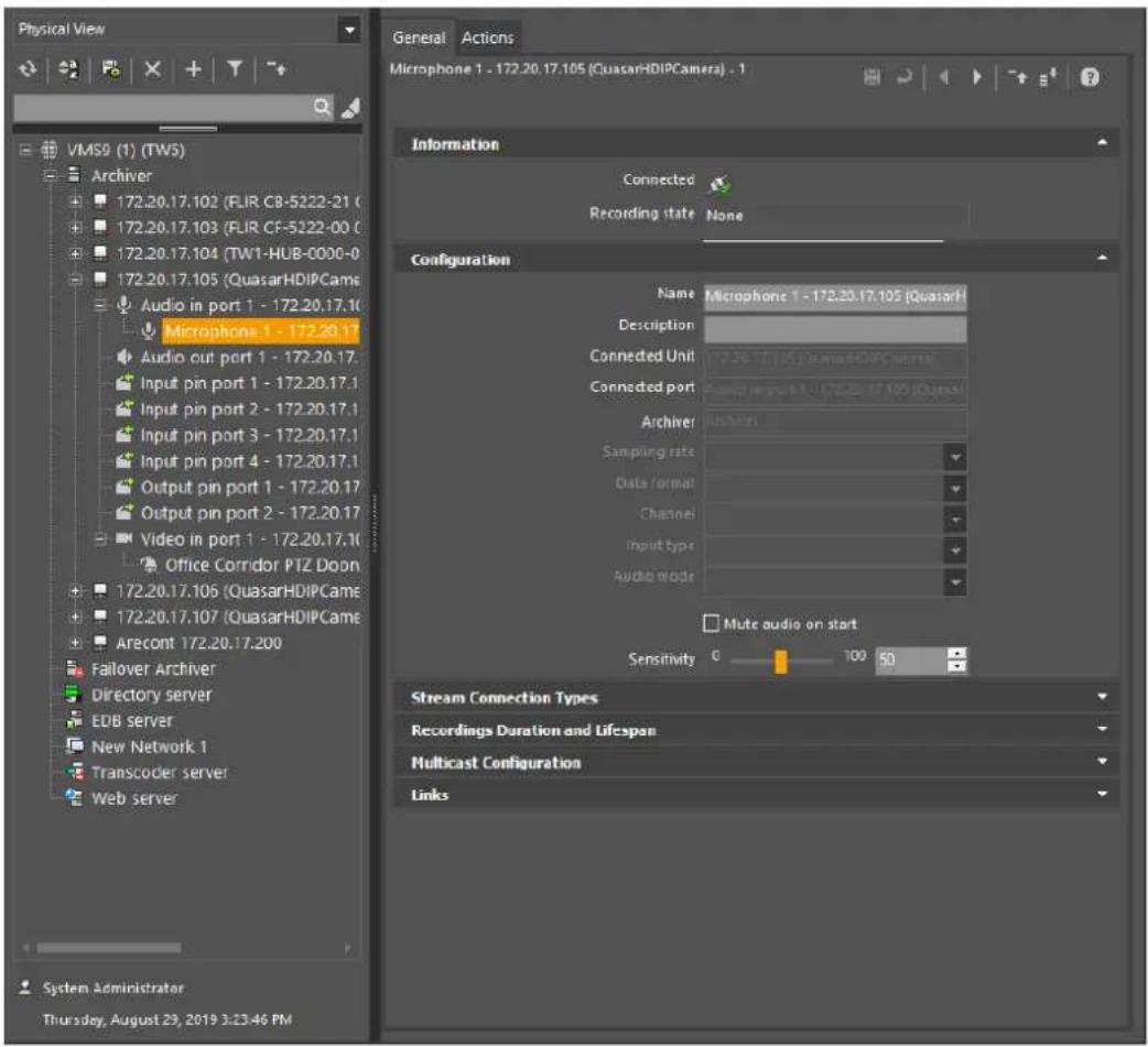
Figure 40 - Microphone Screen
- In the General tab, change default name and modify other settings as needed.
On microphones for intercom use, set the Audio Mode in the Configuration panel to Push to Talk.
- In the Recordings Duration and Lifespan panel, set Manual Recording parameters for microphones.
6.1.2 Link a microphone and/or speaker to a camera
A linked Speaker allows the operator to direct sound (usually from a microphone at the Control Center operator's console) to be played from the speaker associated with the camera.
Follow these steps:
- In the Logical View, select the Camera with which the microphone and/or speaker is to be associated, and open the Linked tab.
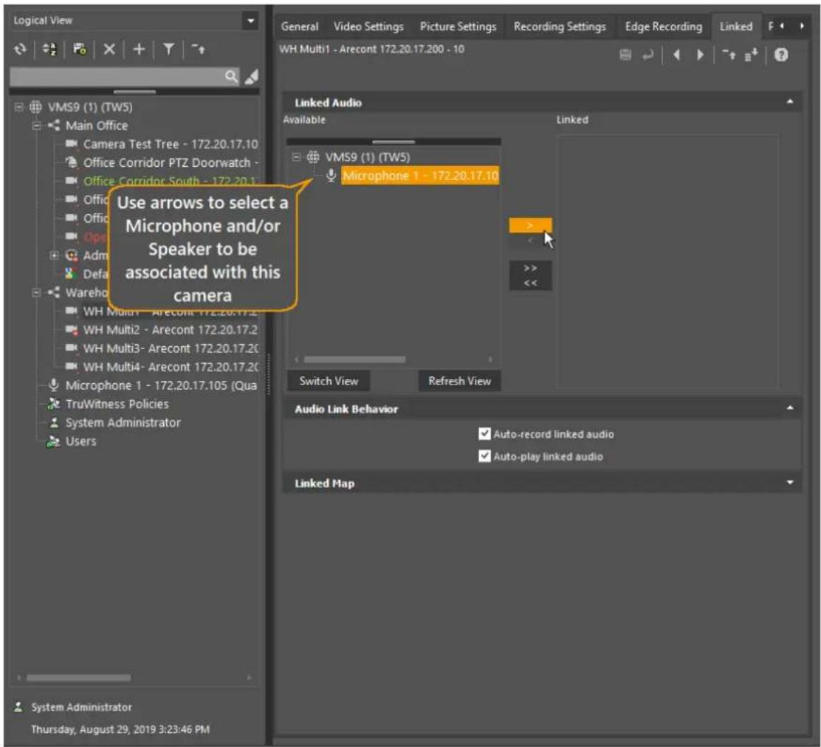
Figure 41 - Camera - Linked Tab
- Select a microphone and/or speaker from the list, and use the add/remove (single) or (multiple) buttons to add them to the list of items linked to the current camera. The Audio Link behavior is set to auto-record and auto-playback Audio with its associated Video.
- Click Save to save the settings associating this Microphone with the current camera
NOTE: For best results, it is recommended that the camera and microphone be from the same vendor.
NOTE: For best results, it is recommended that the camera and microphone be from the same vendor.

7 Logical Configuration
Site/s can be organized according to both their physical structure, that is, how everything is connected, and according to the logical structure of the organization/s that use it to take into account individual needs.
7.1 Enterprises and Sites
Latitude allows you to arrange the Logical view of the system into Enterprises and Sites. By defining these structures, you can show logical entities (cameras, microphones, etc.), 'belonging' to different organizations or locations.
The example below shows how you can start with the entities that comprise the system, add a site ('Main Office', Office Area', Testing Lab', etc.) and drag the entities that are part of that site to its navigation tree, and then add another site ('Parking Area'), and populate the navigation tree for each site by dragging entities from the System root.
Access privileges in the User definitions can be used to grant or restrict operator access to sites. Where several organizations share a system (as in an Office building), the system can be further divided into 'Enterprises'.
Follow these steps:
- Select Logical View from the Sidebar, right-click the System icon, and then select the Add Site option.
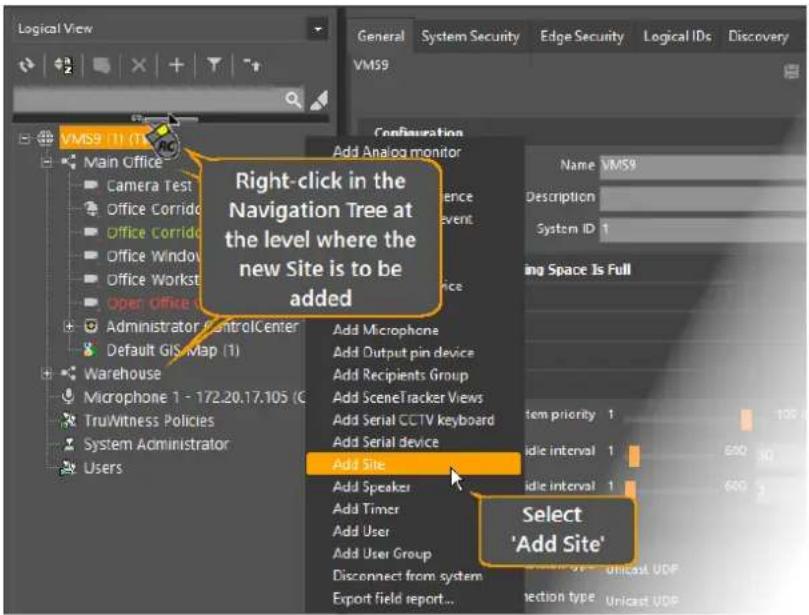
Figure 42 - Admin Center Configuration - Add Site
A new site is added with a default name ('New Site n'), and the Site screen is shown. You can give the site a suitable name and description.
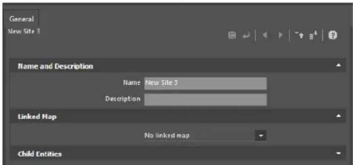
Figure 43 - Name the Site
- Add other Sites if necessary
Note: You can create sites within sites (and sites within enterprises) by right-clicking the applicable sites (or enterprises) instead of on the System root.
- Now you 'drag and drop' entities in the Navigation Tree to the relevant Sites.
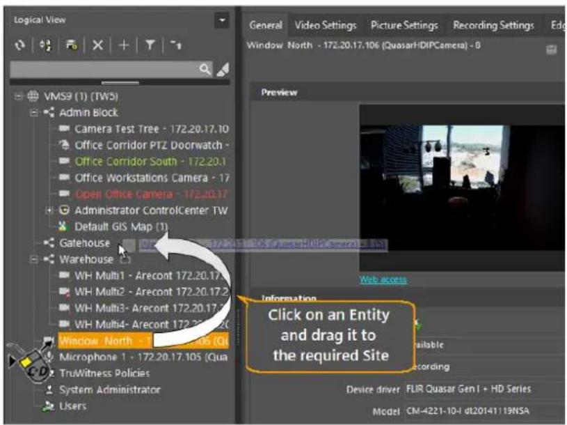
Figure 44 - Drag-and-Drop entities to sites
Note: It is advisable to leave some entities, such as System Administrator, in the System root.
7.2 Sequences
A Camera Sequence is a succession of scenes that can be viewed in a tile.
This section describes how to create a camera sequence in the Admin Center.
Follow these steps:
- In the Control Center, right-click the System icon and select the Add Camera sequence option.
OR
Right-click the Archiver in which you would like to place the sequence.
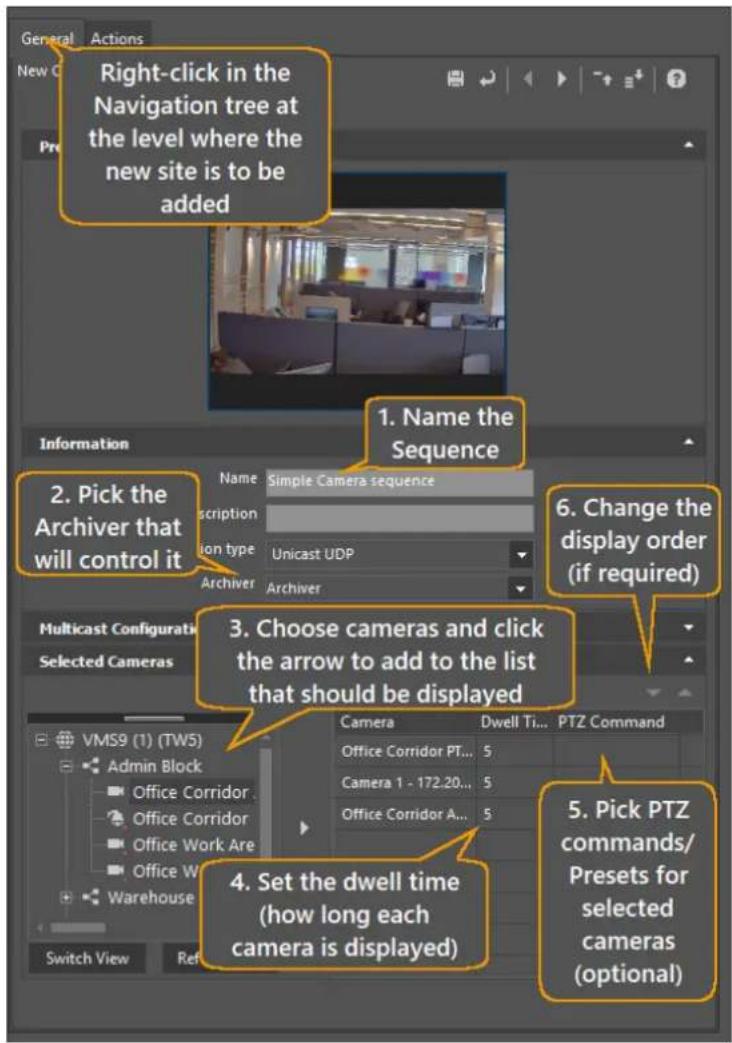
Figure 45 - Camera Sequence
-
Name the sequence and optionally, add a description. If there is more than one Archiver, in the Information panel, choose which Archiver controls this sequence.
-
In the Selected Cameras panel, use the add/remove buttons (▶◀) to choose the cameras from the camera list, and add them to the right-hand list. For each camera, enter the duration (Dwell Time) that it should be displayed.
-
(Optional)
-
To use a Preset view from this camera, use the drop-down to select the Preset.
-
You can change the order of cameras in the Sequence by selecting a camera in the table and moving it using the up and down buttons ( ).
-
Click to save the Sequence.
8 Setting up Specialized Servers
The following are included in this section:
- Web Server
- Transcoder Server
- Gateway Server
- Case Builder Server
8.1 Web Server
A Web Server is needed if Latitude Web Clients are used.
Note: Normally, the Latitude installation includes the IIS configuration required for running the Web Server. For manual configuration, consult the relevant section in the Release Notes.
Add a Web Server
The following describes how to add a web server and various parameter descriptions.
Do the following:
- In the Admin Center, right-click on the System icon in the Physical View and select the Add Web server option.
A new Web server displays with defaults as shown.
Table – Web Server Screen - General Tab
| Field | Default | Notes |
| Information Panel | ||
| Connection Status | ^ Connected, ^[X2C] connected Connected, ^[X2C] connected | |
| Configuration Panel | ||
| Name | New Web server | |
| Description | ||
| Network Address | Enter address of the machine running the WebServer | |
| Reported Address | ||
| Web site is located in virtual directory option | Selected | |
| Virtual directory | Web Client | |
| Port | 80 | |
| Secured Website Port | 443 | See TLS - Setting up Encryption to/from Web Clients |
| External Address |
8.2 Transcoder Server
The Transcoder is a server application that trans-codes the MPEG4 video generated by encoders/IP cameras (and archived by Latitude) to standards-compliant MJPG-over-HTP and standard video streams over RTSP/TCP, for transmission over the Internet.
At least one Transcoder Server is needed in a Latitude system to support connections of Web Clients. It is also needed if the installation is to support remote connection of Clients.
Add a Transcoder
The following describes how to add a transcoder and various parameter descriptions.
Do the following:
- In the Admin Center, right-click on the System icon in the Physical View and select the Add Transcoder option.
A new Transcoder is defined, with defaults as shown.
Table - Transcoder Screen - General Tab
| Field | Default | Notes |
| Information Panel | ||
| Connection Status |  Connected, Connected,  Disconnected Disconnected | |
| Server configuration Panel | ||
| Name | Transcoder server | |
| Description | ||
| Network Address | ||
| External IP | ||
| External Port | 8080 | External and Internal Ports must be the same |
| Internal Port | 8080 | External and Internal Ports must be the same |
| Secured Port | 8081 | Used for TLS communications to Web Clients |
| RTSP Port | 5554 | |
| Default transcoder | deselected | |
| Transcoded stream configuration Panel | ||
| Compression quality | 8 | Range 1 – 10 |
| Maximum frame rate | 30 | Range 1 – 30 |
| Maximum resolution | 240p | |
| Compression | H264 | |
| Global performance limits Panel | ||
| Total CPU % limit | 50% | Range 0 – 100 |
| Above limit enable ‘Key-Frame only’ mode | unchecked | |
| Max. concurrent transcoded frames per second | 100 | Range 50 – 500 |
| Max concurrent client streams | 20 | Range 1 – 100 |
In the Server configuration panel of the General tab, you can edit the transcoder name and provide a description. Enter the network address of the new transcoder, and verify that the port settings are correct for your installation (See the Release Notes for more detail).
Note: If system loading is above the threshold set for the Total CPU % limit setting, transcoder requests are ignored to protect server performance.
8.3 Gateway Server
A Gateway server is needed if remote client applications are to be supported.
Add a Gateway Server
The following describes how to add a Gateway server and various parameter descriptions.
Do the following:
- To add a Gateway server, right-click on the System icon in the Server view and select the Add Gateway server option.
A new Gateway server is defined, with defaults as shown.
Table - Gateway Screen - General Tab
| Field | Default | Notes |
| Information Panel | ||
| Connection Status | Connected, Disconnected | |
| Uptime | ||
| State | ||
| Version | ||
| Configuration Panel | ||
| Name | New Gateway server | |
| Description | ||
| Network Address | Enter address of the machine running the Gateway Server | |
| Reported addresses | ||
| Routing | ||
| Enable Gateway routing | ||
| Port |
If external connections are used for connecting mobile devices, you must provide the IP of the server and configure a port in consultation with the installation's IP department.
8.4 Case Builder Server
A Case Builder server is needed so that Control Center operators can open cases, add clips and other files, and export the cases.
Add a Case Builder Server
The following describes how to add a Case Builder server.
Follow these steps:
- Create a network-shared folder for the CaseBuilder files storage location.
-
In the Admin Center, right-click on the System icon in the Physical View and select the Add CaseBuilder server option.
A new CaseBuilder server is defined. -
In the General tab/Configuration panel, in the Network Address field, enter the address of the machine running the CaseBuilder Server.
-
Open the Case Builder tab, and in the Data Location panel, enter the network-shared folder path you created in Step 1 and click Test to verify that the folder is accessible.
9 Alarm Management
An alarm is a special type of event that prompts users for a response rather than just providing a notification.
Alarm definitions are set up and initiated as follows:
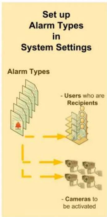
flowchart
graph TD
    A["Alarm Types"] --> B["Users who are Recipients"]
    B --> C["Cameras to be activated"]
    D["User"] --> E["Cameras"]
    F["User"] --> G["Cameras"]
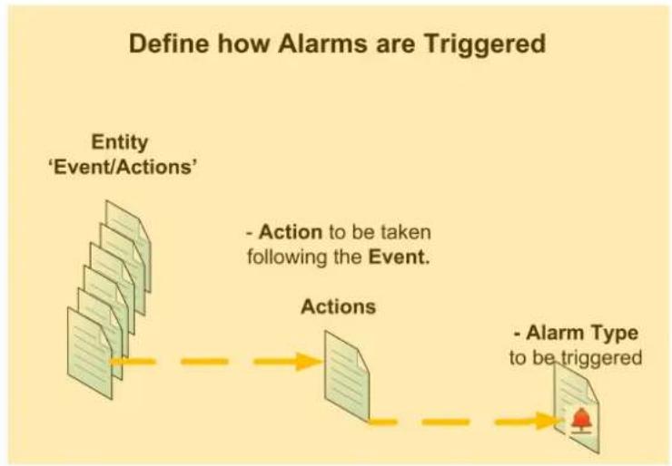
flowchart
graph LR
    A["Entity 'Event/Actions'"] --> B["Actions"]
    B --> C["Alarm Type to be triggered"]
    style A fill:#f9f,stroke:#333
    style B fill:#ccf,stroke:#333
    style C fill:#cfc,stroke:#333
Figure 46 - Set Up and Initiate Alarms
9.1 Set up Alarm Types
This section describes how to set up alarm types in the Admin Center.
Follow these steps:
- From the System Settings view, right-click on Alarm Types select the Add Alarm type option.
The new alarm type configuration begins in the General tab.
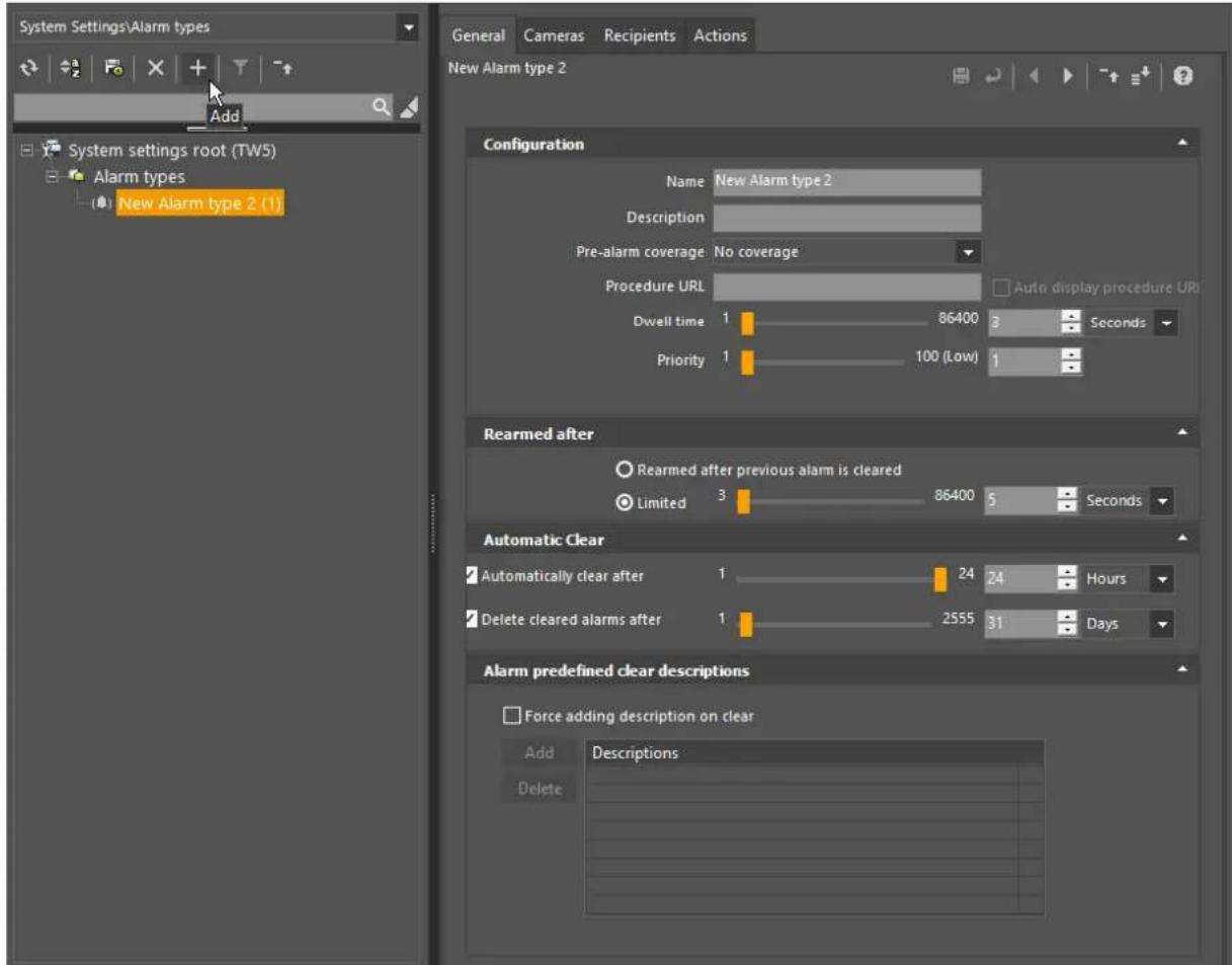
Figure 47 - Define an Alarm Type
General Tab
Name the Alarm type (and if required) adjust the default values.
Cameras Tab
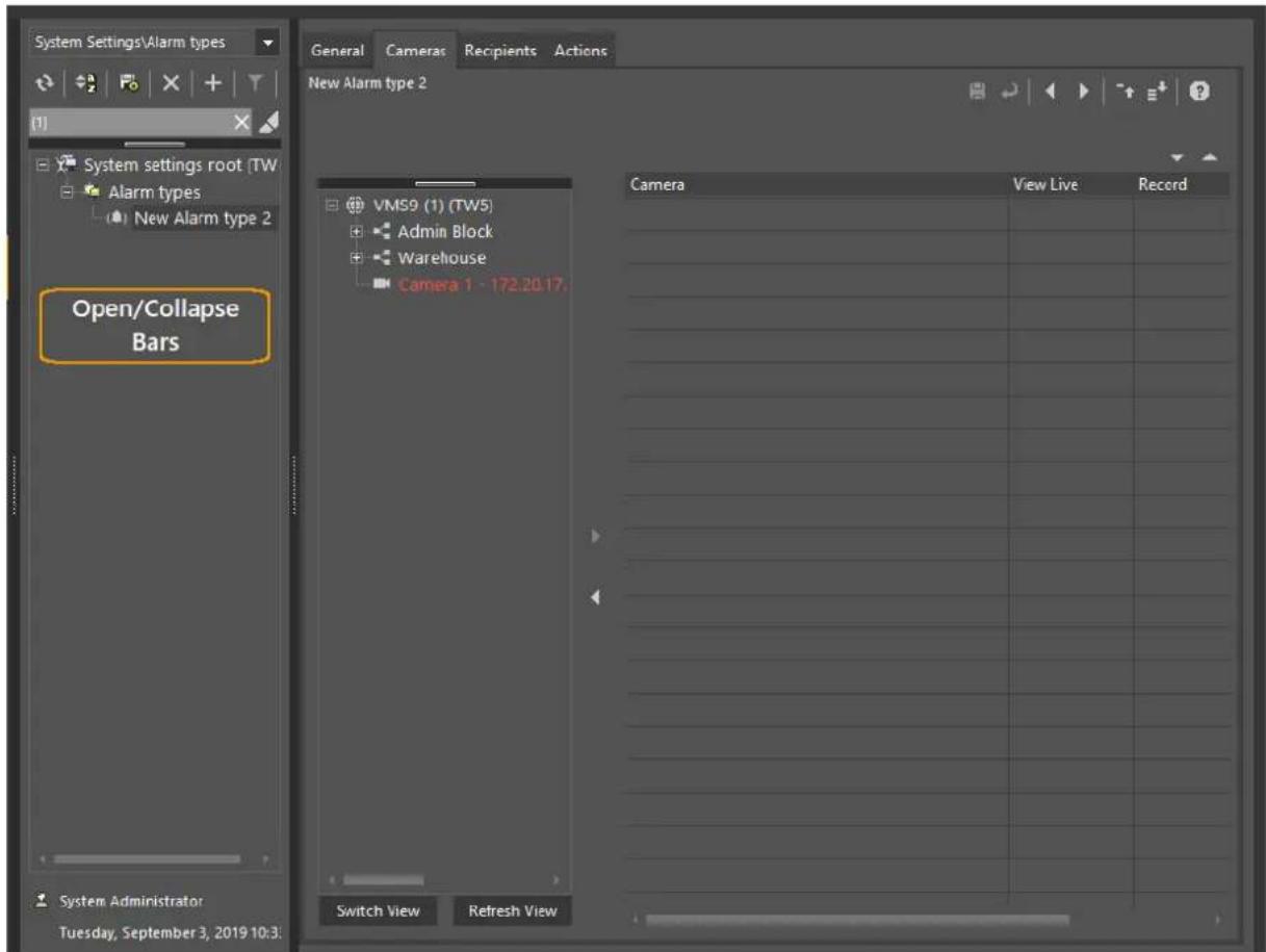
Where more than one camera is associated with an alarm, you can specify the Dwell Time (the amount of time each camera or clip is displayed before the next scene is shown) in the General tab of the alarm type's configuration pane. This tab is also used to Configure parameters such as Priority (which determines which alarms are shown if there are more active alarms than armed tiles in ControlCenter), Pre-alarm Coverage, and others.
2. Configure the remaining Alarm Type tabs, including:
Select Recipients – Users who receive alarm notification and can process it.
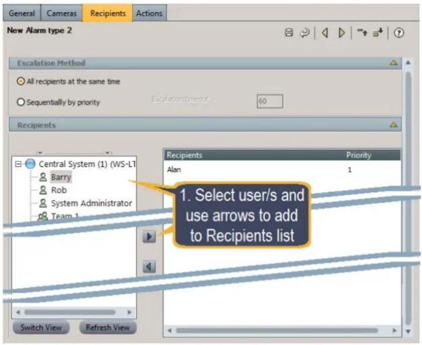
Figure 48 - Add Alarm Recipients
- (Optionally) Add Cameras to be activated by the alarm (content from these cameras is displayed on the Control center when the alarm is triggered).
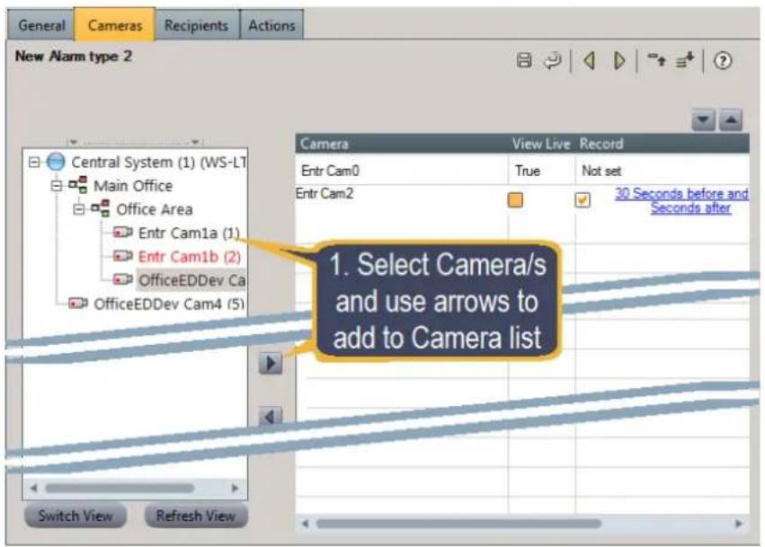
Figure 49 - Select cameras to be displayed for this Alarm Type
- For each selected camera, you can click on the camera entry to display check boxes that enable you to configure when and for how long the camera content is used.
a. View Live – Select/deselect the View Live option to display/not display the Live Content. b. Record – Select/deselect the Record option to enable recording of the selected camera related to the Alarm.
The current record parameters display as a link. Initially, the parameter displays Not set. Clicking on the link opens a "pre-alarm/post-alarm" edit window where the recording parameters can be changed.
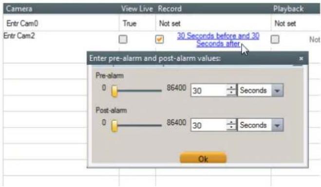
Figure 50 - Alarm Type - Camera Record Settings
c. Playback – Specify playback time before and after the alarm. The same "pre-alarm/post-alarm" edit window opens allowing parameters to be set for Playback.
9.2 Set up how the Alarm is Triggered
This procedure describes how to trigger an alarm.
Follow these steps:
-
From the Actions tab of an entity, select the Events/Actions to trigger the alarm.
-
Right-click on the Events/Actions and select the action to be carried out from the available list.
The selected action displays under the Events/Action in the tree.
- Right-click on the action and select the Trigger Alarm option.
The Coverage pane displays where you set action details.
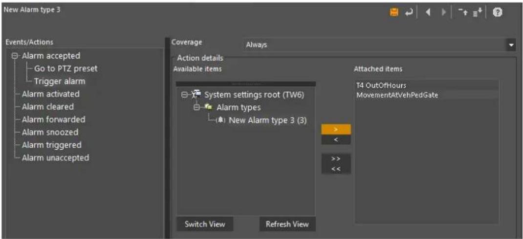
- Complete the Action parameters, including
a. Select the Coverage during when the process is active.
b. Select the Alarm types triggered from the list of Alarm types.
- Click to save the alarm trigger.
For more information on Alarms, see the Help file.
10 User Management
Latitude features a robust privileges model that enables administrators to control user access to virtually every functionality and for every entity in the system. You can set these rules for each individual user in the system, and for each separate entity.
However, to make the rules easier to use, the system also allows rules to be copied ('inherited'). For example, you can set rules for a 'User Group', and then all members added to the group 'inherit' those rules.
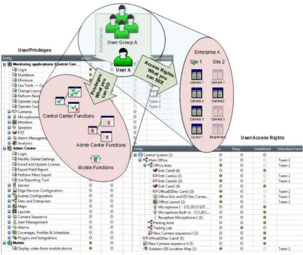
flowchart
graph TD
    subgraph User/Privileges
        A["User Group A"] -->|Inheritance| B["User A"]
        B --> C["Control Center Functions"]
        C --> D["Admin Center Functions"]
        D --> E["Mobile Functions"]
    end

    subgraph Enterprise A
        F["Site 1"] --> G["Camera 1"]
        F --> H["Camera 2"]
        F --> I["Camera 3"]
        F --> J["Layout 1"]
        F --> K["Sequence 2"]
    end

    style User/Privileges fill:#f9f,stroke:#333
    style Enterprise A fill:#bbf,stroke:#333
    style Control Center Functions fill:#dfd,stroke:#333
    style Admin Center Functions fill:#dfd,stroke:#333
    style Mobile Functions fill:#dfd,stroke:#333
Figure 51 -User Groups, Users, Privileges and Access Rights
It is convenient to think of the system as requiring several user levels – One or more Administrators, a number of Supervisors, and several groups of Operators. The entities making up the system can also be thought of as being grouped – the equipment/resources for different locations (Sites) – and sometimes different organizations (Enterprises).
Typically, one would define the User Groups so that all members of each group have similar rules. That way, when you define a new user, they can be placed into the correct group where their rules can be inherited from the group. For example:
Administrators can use all functions and view all entities.
Supervisors can view all entities in the Enterprises and on the sites they are responsible for, and carry out all Operator functions.
Operators can only view live and recorded content, and accept and close alarms related to the areas for which they are assigned.
10.1 Defining User Groups and Users
This procedure describes how to define user groups and users.
Add a User Group
Follow these steps:
- In the AdminCenter, click User and Groups in the sidebar area, and in the Navigation Tree tools, click the Add toolbar icon
+, and on the context menu, select the Add User Group option.
The User Group/General tab opens.
The system assigns a default name 'New User Group n'.
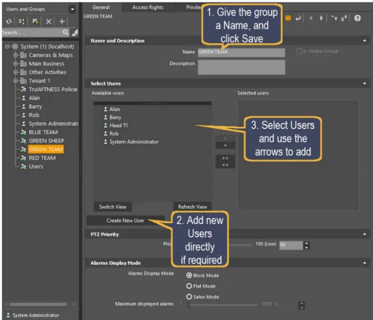
Figure 52 - Defining a new User Group - General
-
Type the name you want for the group, optionally add a description, and click Save (☐). The new user group name is added to the list of 'available users'.
-
Click Create New User to add new users quickly.
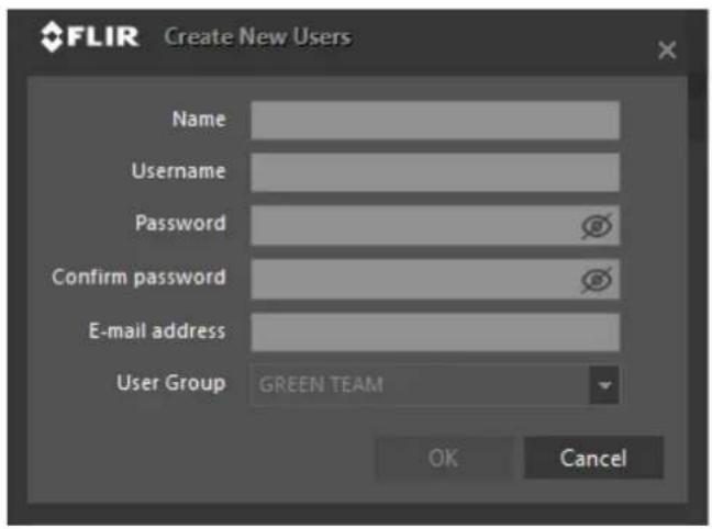
Figure 53 - Quick Create User
4. In the Create New Users dialog, enter the user name, username, password details and (optional) email address, and click OK.
The new user is added to the list of 'available users'.
5. Use the single arrows to move single users into ( ) or out ( ) of the 'Selected users' list.
The double arrows move the whole list at once.
You can then go on to set up the Access Rights and Privileges for the User Group or the individual User.
10.1.1 Access Rights
The Access Rights Tab is shown for User Groups and for individual Users. This tab enables you to determine what entities the user or user group can see.
| Entity | Allow | Deny | Undefined | Inherited From |
| Central System (1) | Og | Og | Og | |
| Main Office | Og | Og | Og | Team 2 |
| Office Area | Og | Og | Og | Team 2 |
| Entr Cam0 (8) | Og | Og | Og | |
| Entr Cam1a (1) | Og | Og | Og | Team 2 |
| Entr Cam1b (2) | Og | Og | Og | Team 2 |
| Entr Cam2 (9) | Og | Og | Og | |
| OfficeEDDev Cam3 (3) | Og | Og | Og | Team 2 |
| Office Entr and ED Dev Camer... | Og | Og | Og | Team 2 |
| Office Layout (2) | Og | Og | Og | Team 2 |
| Microphone 1 - 172.20.17.107 ... | Og | Og | Og | |
| Microphone Built-in - 172.20.1... | Og | Og | Og | |
| Reception Microphone 1 (1) | Og | Og | Og | |
| Parking Area | Og | Og | Og | |
| Testing Lab | Og | Og | Og | |
| New Camera sequence 2 (2) | Og | Og | Og | |
| OfficeEDDev Cam4 (5) | Og | Og | Og | |
| New Camera sequence 3 (3) | Og | Og | Og | |
| Outdoor GIS Location Map (1) | Og | Og | Og | Team 2 |
Figure 54 - Access Rights Tab
To set the Access Rights for this User Group (or this User), check the radio buttons to set those entities (or groups of entities) to Allow or Deny.
- Allow means that the corresponding entity or group is visible to this user or group of users.
- Deny means that the user or group of users do not see this entity or group of entities, and cannot do anything related to it.
- If you click on the radio button for a group entity (e.g. 'Main Site') then all the entities in that group are set to that value together.
Note: For a full description of all the fields in this tab, see the Help file.
10.1.2 Privileges
The Privileges tab lets you define User or User Group functions.
| Entity | Allow | Deny | Undefined | Inherited From |
| Monitoring applications (Control Cen... | O | O | O | |
| Login | O | O | O | Team 2 |
| Shutdown | O | O | O | Team 2 |
| Minimize | O | O | O | Team 2 |
| Use Tools -> Options | O | O | O | Team 2 |
| Change Layout Settings | O | O | O | Team 2 |
| Perform Remote Actions | O | O | O | Team 2 |
| Operate Layout Tour | O | O | O | Team 2 |
| Operate CaseBuilder | O | O | O | Team 2 |
| Cameras | O | O | O | |
| Microphones | O | O | O | |
| Monitors | O | O | O | |
| Speakers | O | O | O | |
| PTZ | O | O | O | |
| Alarm Management | O | O | O | |
| Analytics | O | O | O | |
| Admin Center | O | O | O | |
| Login | O | O | O | |
| Modify Global Settings | O | O | O | |
| Install and Update License | O | O | O | |
| Export Field Report | O | O | O | |
| Perform Mass Export | O | O | O | |
| Use Reporting Tool | O | O | O | |
| Servers | O | O | O | |
| Edge Devices Configuration | O | O | O | |
| Scenes Configuration | O | O | O | |
| Sites and Enterprises | O | O | O | |
| Maps | O | O | O | |
| Layouts | O | O | O | |
| Camera Sequence | O | O | O | |
| User Management | O | O | O | |
| Alarms | O | O | O | |
| Coverages, Profiles & Schedules | O | O | O | |
| Plugins and Integrations | O | O | O | |
| Mobile | ||||
Figure 55 - Privileges Tab
To set the Privileges for this User Group (or this User), check the radio buttons to set those functions (or groups of functions) to Allow or Deny.
- Allow means that this user or group of users can perform this function or group of functions.
- Deny means that the user or group of users cannot perform this function or group of functions.
- If you click on the radio button for a group of functions (e.g. 'Alarm Management') then all the functions in that group are set to that value together.
10.2 Inheritance
To make it easier to set up Access Rights and Privileges for Users, Latitude implements inheritance of these parameters. If you set up a User Group, and specify Access Rights and/or Privileges for the Group, then all Users who become members of that group will 'inherit' the same settings.
11 APPENDIX 1 - 'How to' Configuration Information
11.1 Tips and Tricks using the Latitude Interface
If you are new to Latitude, Welcome!
As you'll see, there is a lot of information to deal with, so we've put lots of 'smart' features in the interface - some from Windows, and some of our own, to help you to get around the very full screens.
Here are some for you to get started with.
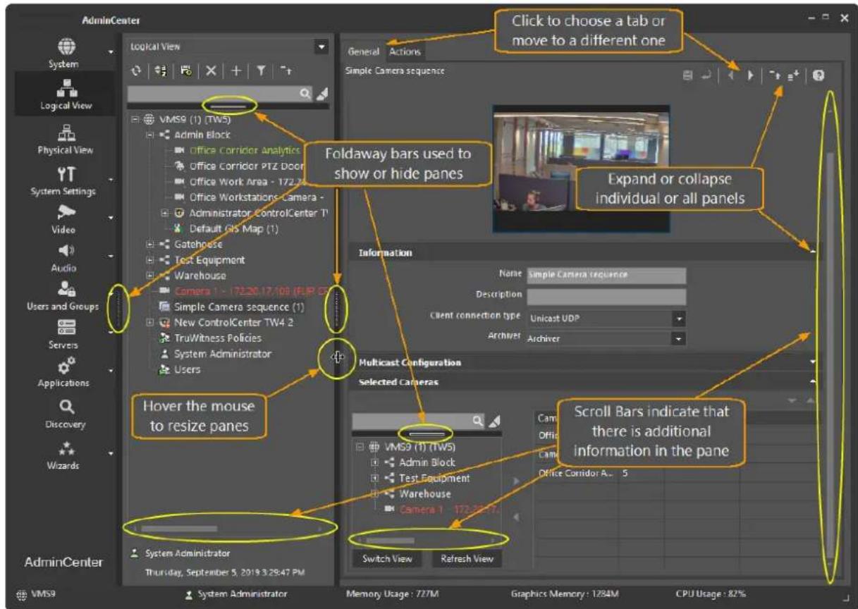
11.1.1 Foldaway Bars
Foldaway Bars let you hide whole screen sections to provide maximum space for viewing details.
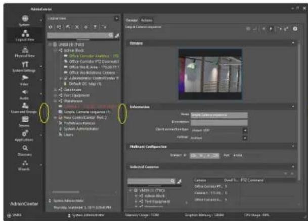
Foldaways Open - View more Panes
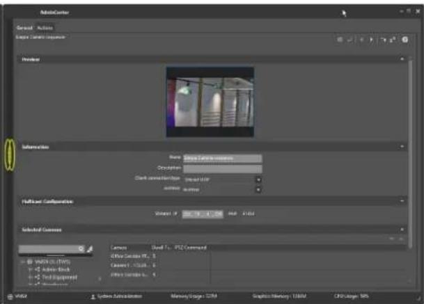
Foldaways Closed - View more Detail
11.1.2 Using 'Switch View' or clicking a node
When looking at items in the Navigation Tree or in Entity lists, there are some tools to help:
- Clicking to open or close Nodes in the tree
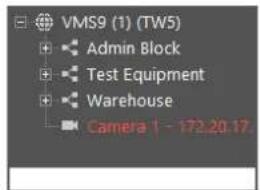
Nodes are closed - click on to open
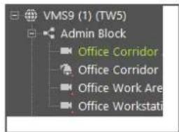
Node is open - click on to close
• Using Switch View to toggle between a Tree or a List
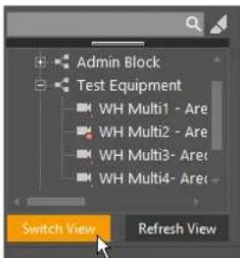
Switch View - Tree view
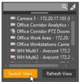
Switch View - List view
11.1.3 Dialogs boxes appear when the item is selected
When a list is shown, the details are expanded as you select an entry.
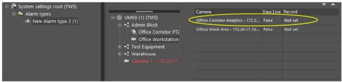
With no entity selected, the data columns provide less detail
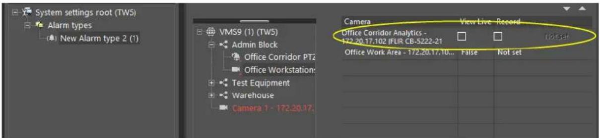
Once an item is selected, available data options and more detail display
Viewing current Settings and entering new settings

USEFUL TIP: Remember - you can use the Foldaway Bars to expand the pane and view more detail
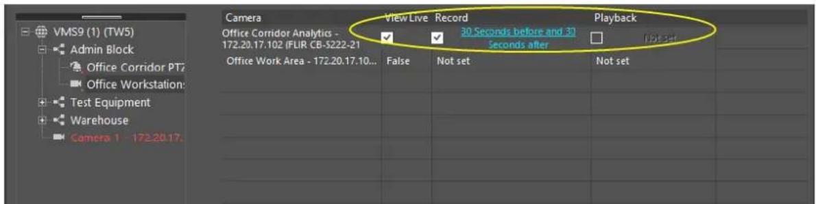
Once items have been selected, you can view their current settings
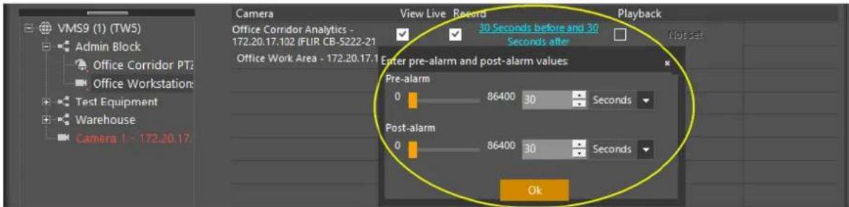
Clicking on a current setting opens the dialog to update it
11.1.4 Search Bar Highlight mode
• Using Free Text Search to List or to Highlight Entities
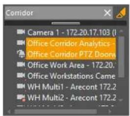
Free Text Search - Only the Selected Items Free Text Search - Highlight the Selected Item
11.2 Define Coverages from the System Settings View
A coverage defines a time span. Coverages (and combinations of coverages called "super-coverages") are commonly used as building blocks when configuring entities, events and actions.
The system comes with always and daytime predefined default coverages. Additional Coverages can be defined as Create a Coverage, or directly in the different Camera screen tabs.
A standard coverage defines time periods for each day of the week and has a start and an (optional) end date. A super coverage is a positive and negative combination of other coverages (including super-coverages) and is used to specify time periods that do not follow weekly schedules, such as holidays.
Note: When configuring coverages, start with standard coverages and then proceed to super-coverages, going from the simplest to the most complex.
11.3 Create a Coverage in System Settings
This section describes how to create a coverage in the system settings.
Follow these steps:
- From the System Setting View, right-click Coverages and select the Add Coverage or Add Super coverage options.
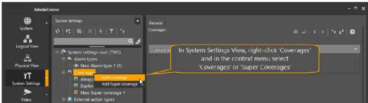
Figure 56 - Admin Center - Add Coverage
When you select Add Coverage, it opens the Create Coverage dialog. A predefined name is allocated to the Coverage, e.g. 'New Coverage n' (you can edit this to make a more meaningful name). The name is added to the list of defined Coverages.
- Use the same steps as in Define a New Coverage from the Camera Screen to define when the Coverage applies.
- Click Save to save the new Coverage.
11.4 Choose an Existing Coverage from the Camera Screen
This section describes how to choose an existing coverage from the camera screen.
Follow these steps:
- Click to add a coverage to this field from those already defined in System Settings. The list of existing Coverages displays.
- Click on a coverage in the list to display the Days/Times when it is active. Use the Switch View button to view additional coverages.
- When you have selected the coverage you wish to use, click OK.
11.5 Define a New Coverage from the Camera Screen
This section describes how to define new coverage from the camera screen.
Follow these steps:
- In the Video Settings, Picture Settings, or Recording Settings, click The Create coverage dialog displays.
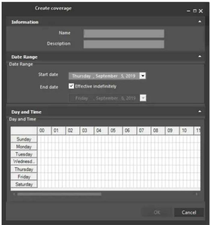
Figure 57 - Admin Center - Define a Coverage
- In the Create coverage dialog, enter a new coverage name and add a description. By default, the new coverage begins on the current date, and is set to be Effective indefinitely. If required, use the drop-down to open a calendar work box, and set a different Start date.
- If an End Date is required, deselect the Effective indefinitely option, and use the drop-down to open the second calendar work box, and set an end date.
- In the Day and Time section, use the mouse to click-and-drag a rectangular area representing the days and times (in 15-minute increments) that make up the Coverage. If non-continuous times are required, hold down the Ctrl key while clicking and dragging the mouse. This allows multiple areas to be defined.
- Click OK to save the Coverage. When the new Coverage has been created, use the steps described above in Choosing an Existing Coverage from the Camera Screen to apply it.
11.6 Create a Video Profile (using System Settings View)
Profiles are sets of values for related parameters used to simplify and expedite the configuration of cameras or other entities.
Table - Video Profile Types
| Profile Type | Description |
| Video | Configures video-specific parameters such as frame rate, bit rate, resolution, and compression method (MJPEG, MPEG4, etc).Note:Default video profiles are predefined in the system for all cameras that are integrated with Latitude. |
| Picture | Configures image display parameters such as gain, brightness, etc. |
| Recording | Specifies recordings' lifespan as well as whether to store motion indications for the recordings. |

NOTE: TEMPLATE - For a particular camera, for each setting type (Video settings, Picture settings, and Recording settings), there can be only one profile per coverage.
11.7 Video Profile Parameters
Profiles are linked to coverages. It is possible to create one profile for each coverage. Latitude comes with a number of pre-Configured profiles, some of which are used when configuring default quality and recording schedules with the Quick Configuration Wizard.
The different profiles are usually added in the respective setting tabs of a camera in the Physical View (Video Settings and Picture Settings). When adding a coverage to a camera, a predefined profile can be selected from the drop-down list or a profile can be customized. The selected coverage and its profile appear in the Summary pane of the relevant tab of the camera entity.
Directly Access Generic Profiles
You can directly access generic profiles.
Do the following:
- To access generic Profiles directly, expand the System Settings drop-down menu in the Sidebar, and then select Profiles.
Add a Custom Video Profile
You can add a custom video profile.
Do the following:
- Right-click the Profiles branch in the System Settings root tree of the View Selection pane and select the Add Video Profile option. The customized profiles are accessible via the Profile drop-down list of the relevant camera setting tabs.
When defining new profiles, each profile type has its own set of parameters, and is initially populated with default values.
11.8 Video Profile
The video profile enables you to create a name and description, and set various configuration settings such as bit-rate, frame rate, storage space, compression, etc.
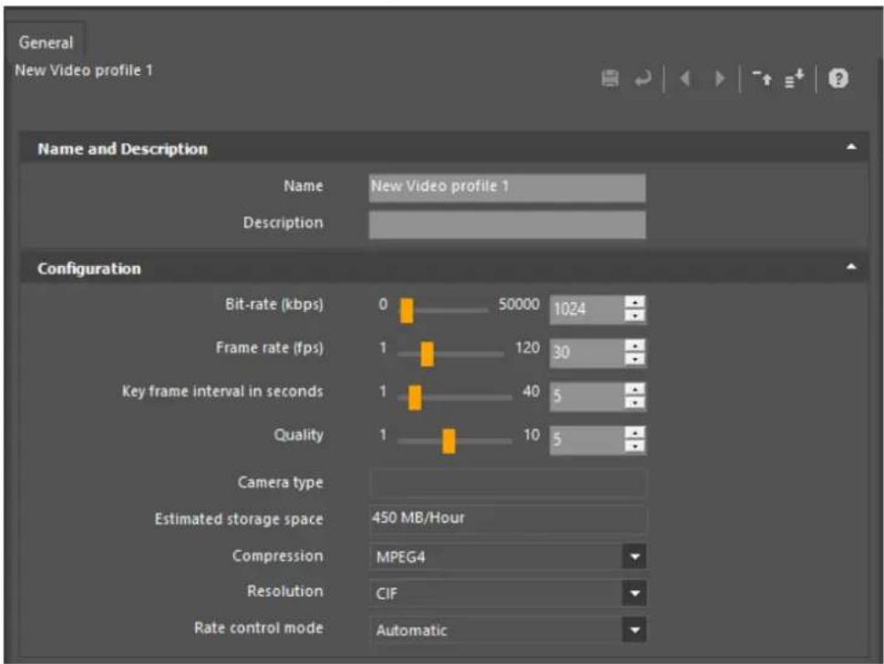
Figure 58 - System Settings - Video Profile with Default Values
11.9 Create Schedules (using System Settings View)
Schedules are used to associate a coverage ("when") to a profile ("how") to applicable entities such as cameras and microphones ("what").
The system uses the following schedule types:
- Picture – Advanced capability: Schedules are not normally used to control Picture Profiles.
- Live Video Quality – Enables you to set coverages during which different Live Video Quality Profiles are to be applied.
Note: For single-stream cameras, this schedule is used for both Live Viewing and Recording.
- Recorded Video Quality – Enables you to set coverages during which different Recording Quality Profiles are to be applied.
Note: This schedule type is only available for cameras with dual-stream capability.
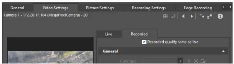
Figure 59 - Camera that supports Dual streams
- Recording – The recording schedule sets coverages during which recording is required The configuration panes for all schedules take the same basic form:
- The General tab is used to specify a coverage and profile. Choose your desired coverage and profile from their respective fields.
- The Attached Schedule tab is used to apply the schedule to entities. Use the arrow and double arrow buttons to move entities between the Available Entities and Selected Entities boxes.
It is possible to attach units to predefined schedules. The common procedure is, however, to access the desired camera and select the desired coverage and profile directly in the different Setting tabs.
11.10 Create a New Schedule
This section describes how to create a new schedule.
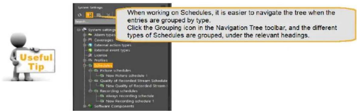
Follow these steps:
- From the System Settings view, right-click Schedules and select a Add
Schedule option.
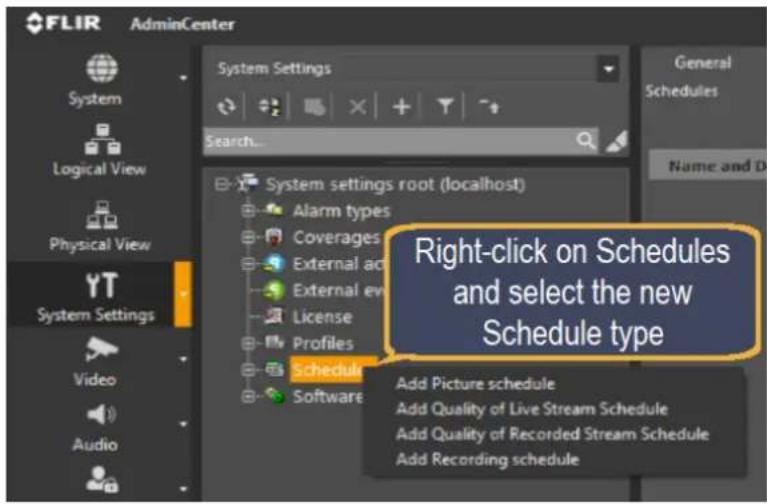
Figure 60 - Admin Center - Add Schedule
The new schedule General tab opens with a default name New
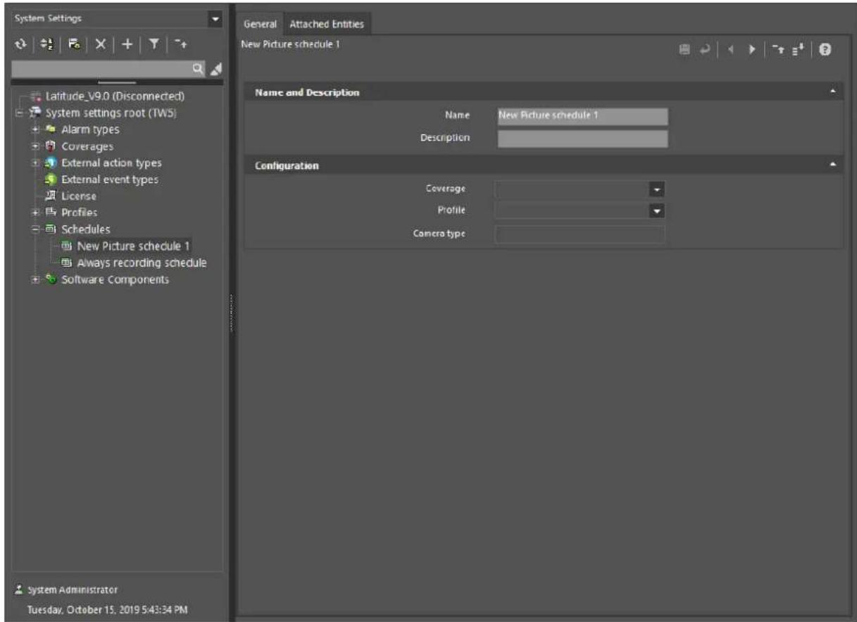
Figure 61 - System Settings - Add
- In the Name and Description section, enter a new name for the coverage, and if required, add a description.
- In the Configuration section, use the drop-down arrows to select a Coverage and a Profile for this schedule, and enter a Camera type.
- Open the Attached Entities tab, and in the Attached Entities section use the arrows to select which camera/s should be associated with this schedule.
- Click the Save icon ( ) to save the schedule.
11.11 Configure Actions and Events
The Actions tab allows you to select an Event that can be sensed, and associate an Action that must be carried out when that event occurs.
Follow these steps:
- From the Actions tab of any entity, you can open a list of the events that can originate from that type of entity.
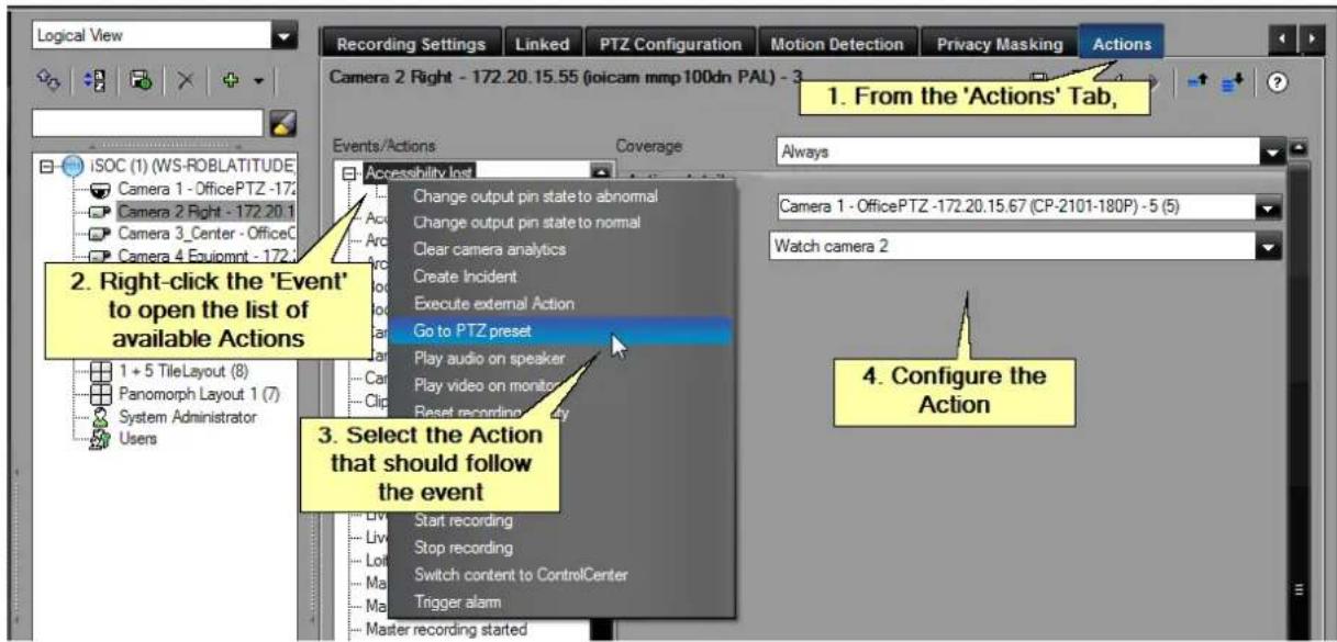
Figure 62 - Configuring an Action
- From the list of available events, right-click on the Event which you wish to use as the trigger for the action.
The list of available Actions is Displays.
- Click on the required action.
Once an action is selected, it is added as an entry under the event in the Navigation tree, and a default Coverage of Always is associated with it.
You can choose a different coverage from the drop-down.
- Complete the configuration of the action, selecting from the information provided in the Action details pane, and click the Save icon (☐).
11.12 Binding Encoders and Cameras
You can "bind" a TRK-101 or TRK-101-P encoder to a camera from the Latitude AdminCenter.
Binding enables functionality such as providing Analytics on the camera scene, or allowing PTZ tracking of moving objects.
Binding Steps Summary (full description in the Help file)
The following procedure describes the binding steps.
Follow these steps:
-
Use the Analytics tab in the System/General Screen to show the available cameras in the system.
-
In the Configure Security Settings section, do the following:
a. Use the Select arrow to select the camera to bind to the Encoder in the Available Cameras section.
b. In the Analytics Device IP column, enter the Encoder IP address.
c. In the Connection Type column, use the drop down option to select the Connection Type details, and click to save the settings.
- Use the Encoder's Web interface to configure the required Analytic settings.
11.13 System-Wide Events
Normally, events are tied to specific entities, and actions generated by them are only triggered when that event occurs for that specific entity. The system also allows the definition of system-wide events – that is, events are recognized when they occur, regardless of the specific entity to which they are related.
The available system-wide events are listed in the iSOC Screen/Actions tab.
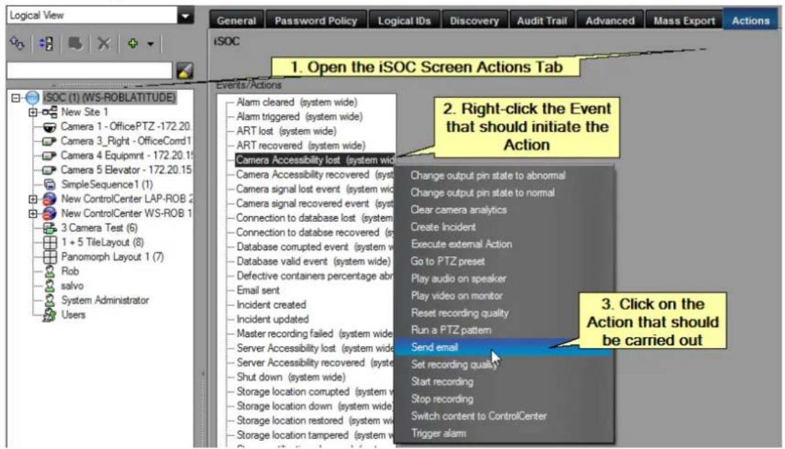
Figure 63 - Selecting a System-Wide Event
To configure a system-wide event, follow these steps:
- Open the iSOC Actions tab, and right-click on the event which should initiate the Action. The list of available actions displays.
- Select the required Action from those marked 'system-wide'.
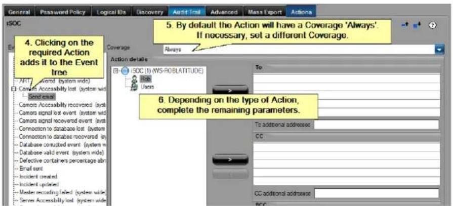
Figure 64 - Configuring the Action associated with the System-Wide Event
- Click on the selected Action to add it to the Event Tree. If the action is not to be applied all the time, use a different Coverage.
- Complete the fields required for this Action, and click the Save icon
11.14 TLS - Setting up Encryption to/from Web Clients
TLS - Transport Layer Security
As more users take advantage of the Latitude Web Client, it becomes more important to protect the system from unauthorized access via Internet connections. Latitude allows the user to use standard Internet security infrastructure to protect communications between the System and any Web Clients. The user purchases a TLS Certificate from a trusted Certificate Provider, and installs it on their system. Once the certificate is loaded into the Latitude, the system encrypts all connections to and from Web Clients.
Summary of Required Steps:
(A full description of these steps is included in the Latitude Admin Center Help file.)
- In consultation with you IT department, acquire a TLS Certificate and place it in the system.
- Ports: The required ports for encrypted communications are set up by default. The IT department should confirm that there are no conflicts (and if required, suitable adjustments must be made.)
- From the System/General/IP Security panel, follow the process to 'Load' the TLS Certificate.
12 APPENDIX 2 - Admin Center - User Interface Details
The default setting for the Admin Center opens the application at the Dashboard screen which provides a system status summary – from here you click on any of the buttons in the Sidebar on the left of the screen to navigate to the different filtered views of the Main Screen, to the Wizards for specific tasks, or to the other Applications that are available.
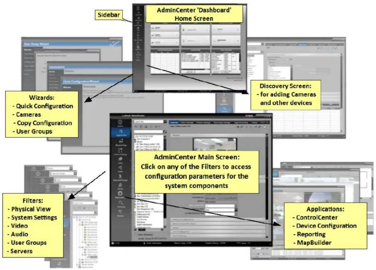
Figure 65 - Admin Center Main Screen Workspace
Note: Access the online Help system at all times by clicking on the Help icon, in the top right-hand corner of the screen. Help is context-sensitive, so whatever screen you are in, the Help system displays the details of the parameters relevant to that screen.
12.1 Main Screen
The Admin Center workspace is divided into the following sections:
- Sidebar
- Selection Pane (Navigation Tree)
- Configuration Pane
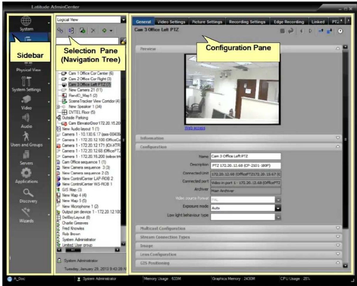
Figure 66 - Admin Center - Main Screen Panes
The Sidebar provides access to specific system views and launches system applications.
The Navigation Tree Pane enables the user navigate to other system entities.
The Configuration Pane provides access to all the parameters of the entities making up the system. Any entity – a camera, an encoder, one of the system servers, or even the definition of a particular user - can be called up by selecting it in the Navigation Tree Pane.
12.2 Sidebar
The Sidebar provides the user quick access to filtered views of the system, and easy activation of common tasks.
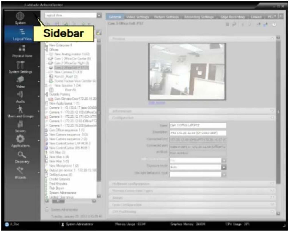
Figure 67 - Admin Center Main Screen Sidebar
Click on any Sidebar component to select the corresponding view in the Selection and Configuration panes. (See table below).
Table - AdminCenter/Main Screen/Sidebar Components
| Icon | Description |
| iSOC | Clicking on the System icon shows the Dashboard (i.e. the system summary) |
| Logical View | Shows a Navigation tree that organizes the software configurations and security “logical” entities into one view. |
| Physical View | Shows a Navigation tree that contains a systems and hardware-centric view |
| System Settings | Provides access to System Configuration Sub MenuThe drop-down arrow lets you access the following directly: |
| Video | Displays a filtered Logical View that only shows video related entities (i.e. Cameras and Monitors)The drop-down arrow lets you access the following directly: |
| Audio | Displays a filtered Logical View that only shows audio related entities (i.e. Microphone and Speakers), or gives access directly via the submenusThe drop-down arrow lets you access the following directly: |
Users and Groups 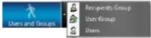 | Displays a filtered Logical View that only shows Users and User Groups), or gives access directly via the submenusThe drop-down arrow lets you access the following directly: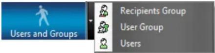 |
Servers 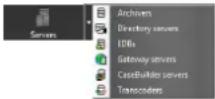 | Displays a filtered Physical View that only shows the Server related entities.Relevant sever pages can be accessed directly from the submenu.The drop-down arrow lets you launch applications directly from the Sidebar: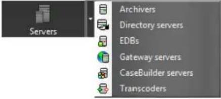 |
Applications | Opens submenu with Latitude-related ApplicationsThe drop-down arrow lets you access the following directly: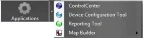 |
Discovery | Opens the Discovery tab in the Settings Area for adding Edge Devices to the system |
Wizards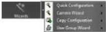 | Displays submenu for selecting Wizards that help guide the User through the steps of creating and configuring the systemThe drop-down arrow lets you access the following directly: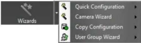 |
Minimizing the Sidebar
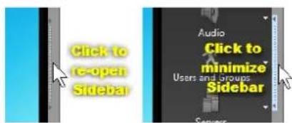
Note:
The Sidebar can be minimized and re-opened by clicking on the 'Minimize' symbol.
12.3 Dashboard
The Dashboard provides a managerial snapshot on various system-wide activities and settings. By viewing the Dashboard, you can view the status and data of the different components managed via the AdminCenter. You can also quickly identify and repair inaccessible cameras by clicking on the highlighted text.
The Dashboard displays when the Latitude AdminCenter starts up, and can be displayed at any time by clicking on the iSOC icon in the sidebar.
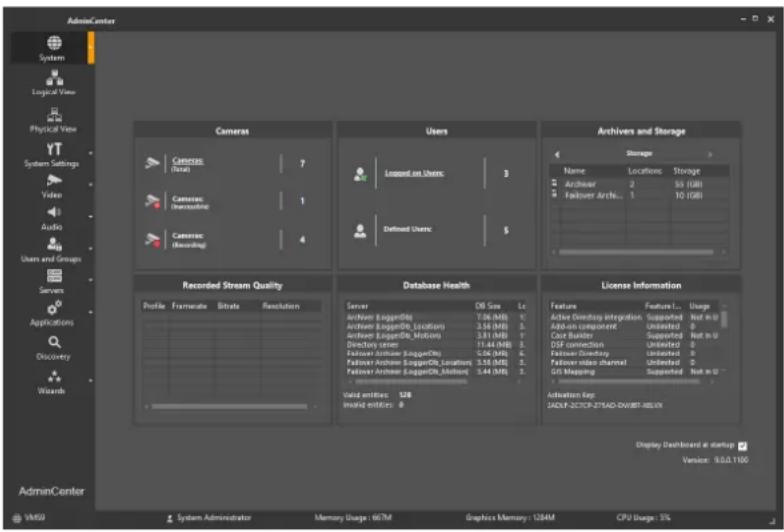
Figure 68 Dashboard - the iSOC 'Home' Screen - Displays a System Summary
Dashboard information is organized in the following panes:
Cameras
Users
Archivers and Storage
Recorded Stream Quality
Database Health
License Information
Note: Deselect the Display Dashboard at startup option to not display the Dashboard on startup.
12.3.1 Camera Pane
This pane contains detailed data on the cameras currently defined in and attached to the system.
Click each option to drill-down to a detailed list of cameras and their status.
You can display more information by clicking on the underlined words.
A summary of the corresponding camera information displays:
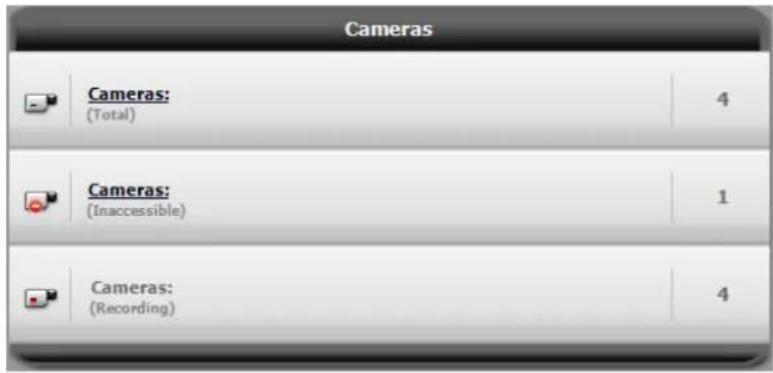
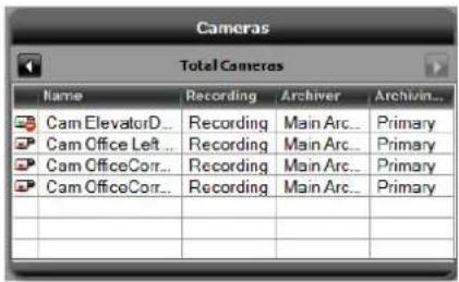
Figure 69 - Dashboard - Cameras Pane
12.3.2 Users Pane
The Users pane lists the number of currently logged-on and defined users
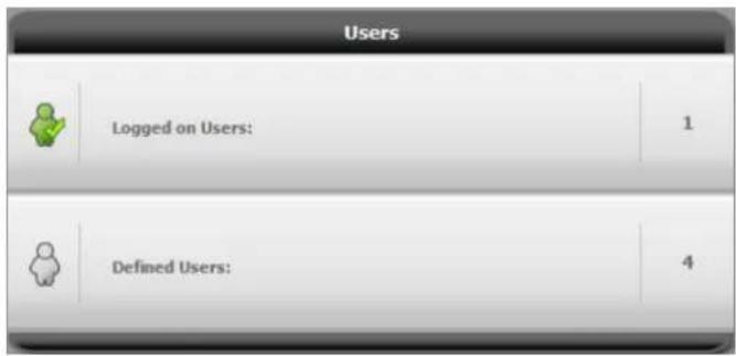
Figure 70 - Dashboard - Users Pane
12.3.3 Archivers and Storage Pane
The Archivers and Storage pane details data on all Archivers, attached video devices, and currently defined storage. Click each option to drill-down to a detailed list of Archivers and cameras attached to the Archivers, and the storage units and their status.
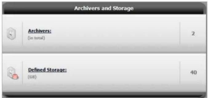
Figure 71 - Dashboard – Archivers and Storage Pane
You can display more information by clicking on the underlined words. A summary of the corresponding Archiver and Storage information is shown:
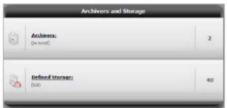
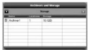
12.3.4 Recorded Stream Quality Pane
The Recorded Stream Quality pane displays recording video quality profiles currently defined in the system.
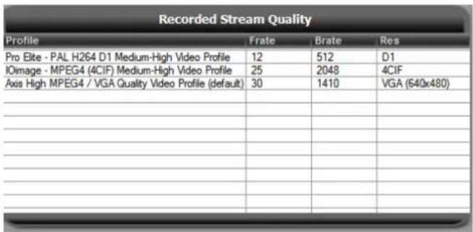
Figure 72 - Dashboard - Recorded Video Quality Pane
12.3.5 Database Health Pane
The Database Health pane displays database size, log size, and server status currently defined in the system.
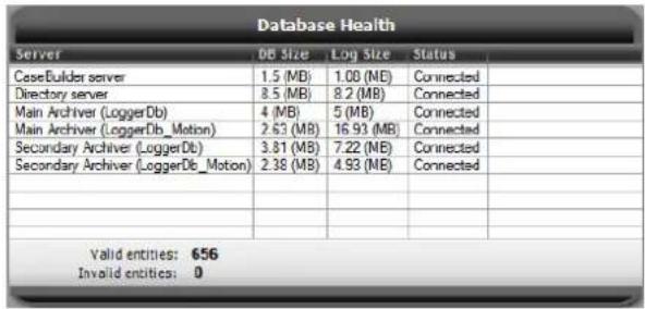
Figure 73 - Dashboard - Database Health Pane
12.3.6 License Information Pane
The Latitude Directory Server holds all the license information for the installation. Licenses cover which components may be used and the number of servers, backup servers and clients that may be used.
You can see detailed information about the licenses currently activated for the system, including whether you are licensed, how many instances you may use (if applicable) and how many are currently in use.
The Activation Key and License Type are also shown.
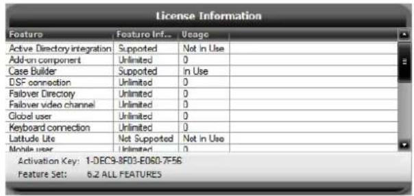
Figure 74 - Dashboard - License Information Pane
12.4 Navigation Tree Pane
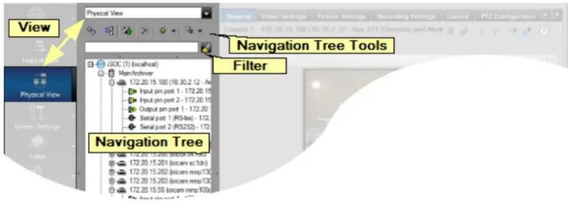
Figure 75 - Admin Center Main Screen – Navigation Tree Pane
12.4.1 View Dropdown - Navigation Tree Pane
The View drop-down enables you to select which system components to display in the Selection Tree.
Do this by selecting a value from the View drop-down box (or by clicking on a Sidebar button). The available views are as follows:
| View | Description |
| Logical View | Logical entities – Cameras, Control, Tile Layouts, User Groups, Users. |
| Physical View | Physical Configuration – Hardware and Server components, Edge Devices. |
| System Settings | System-related entities, such as Alarms, Global Schedules, etc. |
12.4.2 Navigation Tree Tools
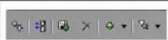
A set of tools is provided to assist you in managing the items displayed. These tools are particularly useful in larger installations, where the list of items in the Navigation tree can be very long.
| Icon | Function | Description |
 | Refresh | Enables the user to refresh the view during editing. |
 | Grouping | Puts all the items in the Selection Pane into their categories. The grouping is alphabetic – i.e. all Cameras, Input Pin devices, Microphones, Output Pin devices, Speakers, User groups, etc.When you want to see all elements of a similar type, such as all Input Pin #1's, or all Microphones, this displays them together, rather than having to scroll through all elements looking for similar sub-components. |
 | CopyConfiguration | (See 5.2.1 - Using ‘Copy Configuration’) |
 | Delete | Deletes the selected item. |
 | Add | Clicking on the pull-down provides quick access to a list of elements that can be added to the configuration. The items available in the list vary depending on the current view. |
 | Filter Tool | Pull-down provides quick access to a list of categories that can be used to filter the current view. The items available in the list vary depending on the current view.(available in the Logical, Physical and System Settings views.One or more filter criteria can be selected at a time. At the bottom of each list there are the general filter options – All, None or ‘No filtering’.) |
12.4.3 Selection Pane Tools – 'Add' options depending on current view
Table - Selection Pane Tools – 'Add' Options Depending on Current View
Add from Logical view
Add from Physical view
Add from Video View
| Add Analog monitor |
| Add Audio layout |
| Add Camera |
| Add Camera sequence |
| Add Enterprise |
| Add Input pin device |
| Add Map |
| Add Microphone |
| Add Output pin device |
| Add Recipients Group |
| Add SceneTracker Views |
| Add Serial CCTV keyboard |
| Add Serial device |
| Add Site |
| Add Speaker |
| Add Tile layout |
| Add User |
| Add User Group |
| Add Active Directory |
| Add Application server |
| Add Archiver |
| Add Archivers failover group |
| Add CaseBuilder server |
| Add Directory |
| Add EDB |
| Add Gateway server |
| Add Mail server |
| Add Network |
| Add SNMP manager |
| Add Transcoder |
| Add Web server |
| Add Analog monitor |
| Add Camera |
| Add Enterprise |
| Add Site |
| Add User |
Add from Audio view
| Add Enterprise |
| Add Microphone |
| Add Site |
| Add Speaker |
| Add User |
Add from Users and Groups
| Add Enterprise |
| Add Recipients Group |
| Add Site |
| Add User |
| Add User Group |
12.4.4 Selection Pane Tools – 'Filter' options depending on current view
Table - Selection Pane Tools – 'Filter' options depending on current view
Filter from Logical view
Filter from Physical view
Filter from System Settings view
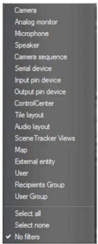
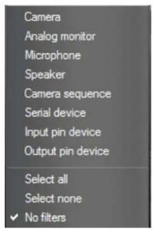
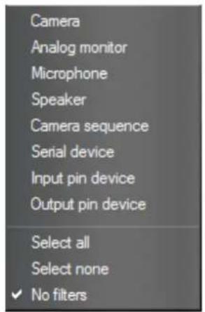
12.5 Configuration Pane
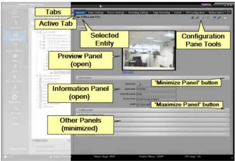
Figure 76 - Admin Center Main Screen Configuration Pane Details
The selected entity details are shown grouped in Tabs, with each tab showing one or more Panels.
You can switch between tabs by clicking on the tab name at the top of the screen.
Panels can be opened and closed by clicking on the maximize and minimize panel icons( ) on the relevant panel header bar.
12.5.1 Configuration Pane Tools

| Icon | Function | Description |
 | Save | The Save button is enabled whenever you have edited the value of a parameter. Your change is only effective after clicking on the Save button. |
 | Undo | While editing, anytime before you click the Save button, you can click the Undo button to clear the changes you have made and revert to the current value. |
 | Back/Forward | These buttons navigate you through the tabs for this element. |
 | Collapse/Expand | These buttons open or close all panels in the current tab. |
 | Help | Opens the context-sensitive Help window. |
13 APPENDIX 3 - License Information
13.1 License Components
Table - License Components
| Feature | Comment |
| Active Directory Integration | Enables the option to integrate with Microsoft Active Directory (AD) - Supported / Not supported |
| Add-on Component | Number of permitted Add-On components -- Add-On component licenses will be provided by DVTEL with the purchase of engineering service integration modules |
| Case Builder | Enables the use of the Case Builder application - Supported / Not supported |
| DSF Connection | The Direct Show Filter connection - Supported / Not supported |
| Failover Directory | The number of failover directory servers in the system, not including the primary directory |
| Failover Video Channel | Number of supported camera scenes or analog monitor scenes for which the Archiver failover mechanism is licensed |
| Global User | Number of global user connection licenses |
| Keyboard Connection | Number of CCTV keyboards concurrently configured in the system |
| Latitude Lite | Enables the use of the Latitude Lite application, which is based on a single server, pre-loaded with the Latitude software, pre-licensed and pre-Configured, to provide a quick and smooth deployment at the customer premises - Supported / Not supported |
| Mobile User | Number of Mobile Users Licensed/Active |
| Mobile Video Feed | Number of Mobile Feeds Licensed/Active |
| Privacy Masking | Supported / Not supported |
| Redundant Channel | Number of supported camera scenes or analog monitor scenes |
| Reporting Tool | Licensed to use Pre-defined Reports - Supported / Not supported |
| SceneTracker Channel | Number of SceneTracker user connection licenses |
| SDK Connection | Number of logins to the Directory server from SDK applications |
| SNMP | Enables the administrator to send out SNMP traps to any 3rd party Network Management System and to Configure which Latitude events will be sent out as traps - Supported / Not supported |
| User Session | Number of concurrently active user sessions logged in to the Directory server |
| Video Channel | Number of supported camera scenes or analog monitor scenes |
| Virtual Video Channel | Number of supported matrix outputs |
| Web Client User | Number of concurrently active Web Client sessions logged in to the Directory server |
13.2 Licensing the Failover Directory
The Failover Directory requires a separate license as it is installed on a machine with a different machine ID.
FLIR issues the necessary licenses on the Licensing Web server.
13.3 Failover Directory License File Installation
This section describes how to install the failover directory license file.
Follow these steps:
- From the AdminCenter, on the System Settings Root — License General Page, click the Failover directory in the Directory Servers list.
- Click Install License to install the license. The Install License dialog displays.
- Follow the same procedures as for activating a regular license, with the exception of using the Machine ID of the Failover directory. See 2 License your Latitude System
Once the Failover Directory has been installed and created in the system, and has communicated with the primary directory, the details of the Failover Directory appear in the Directory Servers list on the System Settings Root/License/General screen.
There is no need to register the customer details since this is not the first activation.
14 APPENDIX 4 - Installation Overview
Full details of the installation process are provided in the version Release Notes. An overview of the procedure is included below.
14.1 Installation Prerequisites
Prior to the installation, verify that the InstConfig.INI file, which should be included in the installation CD or ZIP file, is available in the same directory as the installation executable file.
14.2 Installation Process
This section describes the installation process.
Follow these steps:
1) Insert the Latitude NVMS CD into your CD drive.
If the installation wizard does not begin automatically, browse the CD and double-click the setup .exe file.
If you have the install file on another medium, you can copy it (and the Instconfig.INI file) to you desktop and execute it from there.
2) Before the files are extracted, a message displays providing the installation cache files location, and warning the user that this folder must not be removed.
3) If prompted that your system requires a newer .NET and/or DirectX version, allow the wizard to install the necessary software on your computer, and accept the license agreement.
4) Select an installation folder and set the desired language to be used when working with the Latitude system.
5) Choose the type of Installation you require:
- Client Application Installation - for a computer that is going to be used as a workstation (Only installs the Client Applications)
- Server Installation - when the Latitude services are going to be spread over several computers. If you select this option, select the server that must be installed on this computer.
- All in One Installation - when the Latitude services are going to be run on a single computer
- Custom Installation - allows you to choose specific program features to install – (for advanced users)
6) Components requiring a database:
When installing a component that requires a database, select whether to install a new database or use and existing one. For an existing database, specify the location and login fields.
7) Run the installation process.
8) For a new installation, select Launch AdminCenter on the Installation Wizard Completed screen, and then click Finish, to continue with the instructions to License your Latitude System.
15 APPENDIX 5 - Terminology
The following are Latitude system commonly used terms:
Table - Latitude Terminology Table
| Term | Description |
| AdminCenter | The client application that performs Latitude configuration tasks. |
| ControlCenter | The client application that is used by the operators who monitor the live video material, that handles the system alarms, locates and displays video clips of previous incidents, and prepares material for system export. |
| Edge Device | In the context of Latitude, an edge device is either an IP camera or a video encoder, and in general, any IP device that is managed by the system (other than the servers and client workstations). |
| Entity | Used to refer to any of the addressable edge devices that are connected to the Latitude network. |
| IP Camera | A CCTV camera that can be connected to the IP network and transmits digital video over the network rather than analog over coaxial cables. |
| iSOC | Intelligent Security Operations Center (iSOC). In Latitude Systems earlier than version 6.3, the default name for the ‘root’ of the Latitude System was iSOC. |
 | The default name of the system is now System and this can be viewed in the Sidebar and at the top of all tree diagrams of the system. |
 | The User can change the variable that is shown as the system name, but System remains the name on the system icon. |
| Latitude | The Network Video Management System (NVMS). |
| MJPEG | “Motion JPEG” and is a JPEG-based codec, used in the physical security environment to translate analog video from closed circuit television cameras into a digital stream. |
| MPEG4 | A popular video compression method used in most digital CCTV systems. MPEG4 is the default Video compression in Latitude. |
| Network Switch | A computer networking device that connects network segments. |
| ONVIF | Open Network Video Interface Forum. The ONVIF specification defines a common protocol for the exchange of information between network video devices. It includes automatic device discovery, video streaming and intelligence metadata. |
| OSD | On Screen Display - The system can also provide various additional information called the On-Screen Display (OSD). This can include such parameters as the camera name, address, site name where it is located, date and time it was recorded, image resolution, etc. |
| Scene | A ‘scene’ is a logical entity attached to a physical port. Scenes are the basic elements that appear in a logical tree – such as in the Navigation Tree of the Control Center. A scene is composed of a set of definitions that Latitude applies to a physical device and particular port for example, a camera, with information about the way it is attached – i.e. the port details. |
| Software Services | (or simply “services”) — Programs without a user interface, that run automatically, normally in the background. In Latitude, there are multiple services that act as the server side (back end) of the system, such as the Directory, the EDB and the Archiver. |
| Transport Layer Security (TLS) | Latitude supports encryption of communications between the Transcoder/s and Web Clients. |
| Video Encoder | A device that converts an analog video signal to digital video signal and transmits it over an IP network. In addition to providing a digital image, encoders often provide many of the ‘smart’ digital-camera-style facilities for analog cameras. |
FLIR Systems, Inc.
6769 Hollister Ave.
Goleta, CA 93117
USA
PH: +1 805.964.9797
PH: +1 877.773.3547 (Sales)
PH: +1 888.747.3547 (Support)
FX: +1 805.685.2711
www.flir.com/security
Corporate Headquarters
FLIR Systems, Inc.
27700 SW Parkway Ave.
Wilsonville, OR 97070
USA
PH: +1 503.498.3547
FX: +1 503.498.3153
- Table of Contents
- Introduction ...... 1
- FLIR United VMS Latitude System Overview and Main Components 5
- Licensing your VMS 15
- Using the Quick Configuration Wizard (QCW) 21
- Setting up Cameras in the Latitude System 42
- Setting up other Entities 54
- Logical Configuration 57
- Setting up Specialized Servers 60
- Alarm Management 64
- User Management 70
- APPENDIX 1 - 'How to' Configuration Information .... 75
- APPENDIX 2 - Admin Center - User Interface Details 88
- APPENDIX 3 - License Information .... 102
- APPENDIX 4 - Installation Overview .... 104
- APPENDIX 5 - Terminology .... 105
- Introduction
- Scope
- Finding what you need
- Introducing the System and getting started
- Configuring the System
- Appendices with detailed information
- Intended Audience
- More Information – Help System
- About this File
- FLIR United VMS Latitude System Overview and Main Components
- Servers
- Directory Server
- EDB Server
- Archiver
- Transcoder/s
- Gateway Server
- CaseBuilder Server
- Web Server
- Application Server
- Latitude Clients - Admin Center, Control Center and EZ Web Client
- ADMIN CENTER CLIENT
- CONTROL CENTER CLIENT
- WEB CLIENT
- Security for your FLIR United VMS Latitude System
- System - System Security
- TLS for Edge Devices – Choosing the options
- Web Security
- Users Password Rules
- System - Edge Security
- Security Actions
- Notes:
- Follow these steps:
- Licensing your VMS
- License Information
- System Information
- Licensing a system
- Getting to the Install License window
- Get an Activation Key
- To Generate a License
- Activating the License File using the Client Portal
- Using the Quick Configuration Wizard (QCW)
- Notes on Security
- QCW – Prerequisites
- Starting the QCW
- QCW - Global Settings
- QCW – Archivers
- QCW – Adding a Network
- QCW - Configuring Archiver Storage
- QCW – Discovery
- Automatic and Manual Discovery
- Automatic Discovery
- Discovering FLIR cameras and Encoders
- Manual Discovery
- Adding Generic Cameras
- Configuration:
- Add the Unit to an Archiver manually
- Discover a Unit manually from the Discovery page
- General System Accuracy Method Proprietary ONVIF
- QCW - Attach Cameras to Archiver
- QCW – Quality
- Accessing Applications from the Sidebar
- Accessing Wizards from the Sidebar
- Setting up Cameras in the Latitude System
- Individual Camera Settings – the Camera Parameter Screens
- General Tab
- Note on Coverages and Profiles
- To set a new coverage:
- Video Settings Tab
- To access Advanced Panel settings:
- Picture Settings Tab
- Recording Settings Tab
- To set recording parameters:
- Linked Tab
- PTZ Tab
- PTZ Controls
- Pan/Tilt controls:
- Zoom In/Out:
- Toolbar:
- Motion Detection Tab
- Record upon Motion parameters
- Privacy Masking Tab
- Actions Tab
- System-Wide Events
- Setting up Groups of Cameras
- Using 'Copy Configuration'
- Setting up other Entities
- Microphones and Speakers
- Define a Microphone or Speaker
- Select Add Microphone or Add Speaker.
- Link a microphone and/or speaker to a camera
- Logical Configuration
- Enterprises and Sites
- Sequences
- Setting up Specialized Servers
- Web Server
- Add a Web Server
- Do the following:
- Transcoder Server
- Add a Transcoder
- Gateway Server
- Add a Gateway Server
- Case Builder Server
- Add a Case Builder Server
- Alarm Management
- Set up Alarm Types
- General Tab
- Cameras Tab
- Configure the remaining Alarm Type tabs, including:
- Set up how the Alarm is Triggered
- User Management
- Defining User Groups and Users
- Add a User Group
- Access Rights
- Privileges
- Inheritance
- APPENDIX 1 - 'How to' Configuration Information
- Tips and Tricks using the Latitude Interface
- Foldaway Bars
- Using 'Switch View' or clicking a node
- Dialogs boxes appear when the item is selected
- Viewing current Settings and entering new settings
- Search Bar Highlight mode
- Define Coverages from the System Settings View
- Create a Coverage in System Settings
- Choose an Existing Coverage from the Camera Screen
- Define a New Coverage from the Camera Screen
- Create a Video Profile (using System Settings View)
- Video Profile Parameters
- Directly Access Generic Profiles
- Add a Custom Video Profile
- Video Profile
- Create Schedules (using System Settings View)
- Create a New Schedule
- Configure Actions and Events
- Binding Encoders and Cameras
- Binding Steps Summary (full description in the Help file)
- System-Wide Events
- To configure a system-wide event, follow these steps:
- TLS - Setting up Encryption to/from Web Clients
- TLS - Transport Layer Security
- Summary of Required Steps:
- APPENDIX 2 - Admin Center - User Interface Details
- Main Screen
- Sidebar
- Minimizing the Sidebar
- Note:
- Dashboard
- Camera Pane
- Users Pane
- Archivers and Storage Pane
- Recorded Stream Quality Pane
- Database Health Pane
- License Information Pane
- Navigation Tree Pane
- View Dropdown - Navigation Tree Pane
- Navigation Tree Tools
- Selection Pane Tools – 'Add' options depending on current view
- Selection Pane Tools – 'Filter' options depending on current view
- Configuration Pane
- Configuration Pane Tools
- APPENDIX 3 - License Information
- License Components
- Licensing the Failover Directory
- Failover Directory License File Installation
- APPENDIX 4 - Installation Overview
- Installation Prerequisites
- Installation Process
- APPENDIX 5 - Terminology
Brand : FLIR
Model : Latitude 9.2
Category : Uncategorized