
SkyWatch - Uncategorized FLIR - Free user manual and instructions
Find the device manual for free SkyWatch FLIR in PDF.


| Product Type | Portable Thermal Imaging Camera |
| Brand | FLIR |
| Model | SkyWatch |
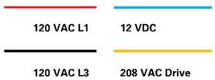
| Dimensions (H x W x D) | 200 x 80 x 60 mm (7.9 x 3.1 x 2.4 in) |
| Weight (including battery) | 500 g (1.1 lb) |
| Battery Type | Rechargeable Li-ion, 3.6 V, 3200 mAh |
| Battery Life | Up to 4 hours continuous operation |
| Display | 4-inch LCD touchscreen, 640 x 480 pixels |
| Thermal Sensor Resolution | 640 x 480 pixels |
| Thermal Sensitivity (NETD) | < 50 mK |
| Temperature Measurement Range | -20°C to 1200°C (-4°F to 2192°F) |
| Accuracy | ±2% or ±2°C |
| Image Modes | Thermal, MSX, Picture-in-Picture, Visual |
| Storage | microSD card (up to 32 GB) |
| Connectivity | USB-C, Wi-Fi (802.11 b/g/n), Bluetooth 4.1 |
| Video Recording | Yes, MP4 format with audio |
| Waterproof Rating | IP54 (splash and dust resistant) |
| Drop Test | 2 m (6.6 ft) onto concrete |
| Operating Temperature | -10°C to 50°C (14°F to 122°F) |
| Warranty | 2 years limited |
Frequently Asked Questions - SkyWatch FLIR
User questions about SkyWatch FLIR
0 question about this device. Answer the ones you know or ask your own.
Ask a new question about this device
Download the instructions for your Uncategorized in PDF format for free! Find your manual SkyWatch - FLIR and take your electronic device back in hand. On this page are published all the documents necessary for the use of your device. SkyWatch by FLIR.
USER MANUAL SkyWatch FLIR
WARNING - This document contains technology whose export, re-export, or transfer to Non-U.S. Persons, wherever located, is subject to the Export Administration Regulations (EAR) (15 C.F.R. Sections 730-774). This document may not be exported, reexported, or transferred without the prior authorization of the U.S. Department of Commerce.
User Guide
For SkyWatch Version 4.0
FLIR Detection, Inc.
7055 Troy Hill Drive, Suite 300
Elkridge, MD 21075
USA
For Customer Service/Part Orders call or email:
SkyWatch.Support@flir.com
© 2012-2020 FLIR Detection, Inc. All Rights Reserved.
FLIR is a trademark of FLIR Systems, Inc. Certain FLIR products and design elements are trademarks of FLIR Systems, Inc. All other product and company names may be the property of their respective owners.
Proprietary Information
The documentation contains confidential and proprietary information that must be maintained in confidence and used only in a manner consistent with the documentation and may not be disclosed to any third parties.
This documentation is provided as a component part of the FLIR SkyWatch surveillance platform. All parties or individuals who are in possession of the documentation accept in full and without exception or limitation the FLIR unrestricted rights of ownership of this material. This documentation is not available by any other means except by license that is only available from FLIR. Under no circumstances may any part or the whole of this documentation be reproduced, stored in a retrieval system, transmitted, copied, modified, distributed, displayed, sold, licensed, published or derivative works created there from in any form or by any means – electronic, mechanical, recording, or otherwise without the written permission of FLIR obtained in advance of the requirement.
It is expressly forbidden for the holder of this documentations to use this documentation either in its entirety or in part or any graphics to provide training or tuition, assistance or knowledge transfer to any other party whatsoever, or for marketing of promotional literature or material of any type whatsoever without the prior written permission of FLIR. Use of this documentation in any manner inconsistent with the user manual and related documentation is strictly prohibited. Use of the documentation is not transferable.
Patents
One or more products or product components may be covered by US and International patents. The SkyWatch is protected by U.S. Patent No. 5.295.555.
CONTENTS
1.0 SAFETY 1
1.1 SAFETY NOTICE CONVENTIONS....1
1.2 SAFETY NOTICES 2
1.3 OPERATIONAL SAFETY 4
1.4 MECHANICAL SAFETY 4
1.5 GENERATOR SAFETY....5
1.6 ELECTRICAL SAFETY....5
1.7 TOWING SAFETY....6
1.8 GENERAL SAFETY 6
1.9 GLOSSARY 7
1.10 REFERENCED MANUALS....8
2.0 SKYWATCH OVERVIEW....9
2.1 GENERAL OPERATION....9
2.2 CONFIGURATION 9
2.3 PLATFORM COMPONENTS....10
2.4 COMPONENT DESCRIPTIONS....11
2.5 SKYWATCH SPECIFICATIONS BY MODEL....12
2.6 PAYLOADS AND OPTIONAL EQUIPMENT 14
2.7 OPTIONAL EQUIPMENT AND SERVICES ....15
3.0 OFFICER'S COMPARTMENT 16
3.1 COMPONENT DESCRIPTIONS....17
4.0 ELECTRICAL COMPARTMENT 19
4.1 ELECTRICAL COMPONENT DESCRIPTIONS ..... 20
5.0 ELECTRICAL SYSTEM....22
6.0 HYDRAULIC SYSTEM 25
6.1 NORMAL OPERATION....25
6.2 EMERGENCY OPERATION 26
7.0 POWER GENERATION 28
7.1 SHORE POWER 28
7.2 DIESEL GENERATOR MODELS 29
7.3 GASOLINE GENERATOR MODELS 31
8.0 CONTROLS AND INDICATIONS....33
8.1 OFFICER'S COMPARTMENT 33
8.2 ELECTRICAL COMPARTMENT....36
8.3 DIESEL GENERATOR CONTROL PANEL....38
8.4 GASOLINE GENERATOR SYSTEM COMPONENTS 39
9.0 TOWING THE SKYWATCH 41
9.1 VEHICLE REQUIREMENTS....41
9.2 UNCOUPLING THE SKYWATCH FROM TOW VEHICLE 42
9.3 COUPLING THE SKYWATCH TO TOW VEHICLE....42
9.4 SAFELY TOWING THE SKYWATCH 44
10.0 SETUP 46
10.1 SITE SELECTION 46
10.2 LEVELING THE TRAILER....47
10.3 MOUNTING THE ANEMOMETER....50
10.4 MOUNTING THE PAYLOADS 51
Figure 1: SkyWatch with Gasoline Generator and 1-Man Cab ....10
Figure 2: Officer's Compartment Interior ....16
Figure 3: Electrical Compartment ....19
Figure 4: Proximity Switch....21
Figure 5: AC System Diagram....23
Figure 6: DC System Diagram....24
Figure 7: Emergency Descent Handle....26
Figure 8: Hydraulic System ......27
Figure 9: Shore Power Connector....28
Figure 10: SkyWatch Diesel Generator 29
Figure 11: Lighting Control Panel ....33
Figure 12: Up/Down Momentary Switch....33
Figure 13: Generator Start/Stop Control ....34
Figure 14: Fuel Gauge....34
Figure 15: Wind Speed Indicator 34
Figure 16: Air Conditioner Controls....35
Figure 17: Heater Control....35
Figure 18: Emergency Descent Handle....35
Figure 19: PA System....36
Figure 20: PA System....36
Figure 21: DC Breaker Panel....36
Figure 22: Power Input Selector Switch ....36
Figure 23: Up/Down Momentary Control....37
Figure 24: Solar Charge Controller Indications ......37
Figure 25: Proximity Switch ....37
Figure 26: Diesel Generator Operator's Panel ....38
Figure 27: Diesel Generator Coolant Level 39
Figure 28: Gasoline Generator Operator's Panel 39
Figure 29: Solar Charge Controller....71
Figure 30: Flow Control Valve....72
Figure 31: Pump Flow Rate Adjustment....73
1.0 SAFETY
1.1 SAFETY NOTICE CONVENTIONS
Operational descriptions and procedures contained in this manual include various warnings, cautions, and notes. The conventions for displaying safety information are as follows:
WARNING! WARNINGS INCLUDE OPERATIONAL CONSIDERATIONS OR LIMITATIONS THAT COULD CAUSE SERIOUS INJURY OR DEATH TO PERSONNEL OPERATING OR MAINTAINING THE PLATFORM. WARNINGS APPEAR IN A RED BOX THE HEADER AND STATEMENT IN UPPER CASE RED TEXT.
CAUTION!
CAUTIONS INCLUDE OPERATIONAL CONSIDERATIONS OR LIMITATIONS THAT COULD CAUSE DAMAGE TO THE PLATFORM, ITS SYSTEMS, OR PAYLOADS. CAUTIONS APPEAR IN A BLACK BOX WITH AN UPPER-CASE RED HEADER AND THE STATEMENT IN UPPER-CASE BLACK TEXT.
NOTE
Notes include various operational considerations or limitations that apply to the platform, its systems, payloads, or personnel operating or servicing these items. Notes appear in a black box with an upper-case black header and the statement in normal black text.
1.2 SAFETY NOTICES
The safety notices provided in this section are for the SkyWatch platform only. In addition to the information provided here, refer to the safety information in the component manuals for safety notices for those specific components.
Failure to follow component safety instructions may result in damage to the component or SkyWatch platform, void the component's warranty, or cause bodily injury or death.
WARNING!
IF YOU BELIEVE THAT YOUR VEHICLE HAS A DEFECT WHICH COULD CAUSE A CRASH OR COULD CAUSE INJURY OR DEATH, YOU SHOULD IMMEDIATELY INFORM THE NATIONAL HIGHWAY TRAFFIC SAFETY ADMINISTRATION (NHTSA) IN ADDITION TO NOTIFYING FLIR. IF NHTSA RECEIVES SIMILAR COMPLAINTS, IT MAY OPEN AN INVESTIGATION AND IF IT FINDS THAT A SAFETY DEFECT EXISTS IN A GROUP OF VEHICLES, IT MAY ORDER A RECALL AND REMEDY CAMPAIGN. HOWEVER, NHTSA CANNOT BECOME INVOLVED IN INDIVIDUAL PROBLEMS BETWEEN YOU, YOUR DEALER, OR FLIR. TO CONTACT NHTSA, YOU MAY EITHER CALL THE AUTO SAFETY HOTLINE TOLL-FREE AT 1-888-327-4236 (TTY: 1-800-424-9153); GO TO HTTP://WWW.SAFERCAR.GOV; OR WRITE TO: NHTSA, US DEPARTMENT OF TRANSPORTATION, 1200 NEW JERSEY SE, WASHINGTON, DC 20590.
WARNING!
DO NOT ATTEMPT TO DEPLOY, USE, OR OPERATE ANY PART OF THE PLATFORM UNTIL YOU HAVE THOROUGHLY READ THIS MANUAL.
WARNING!
DO NOT ALLOW ANYONE TO RIDE ON THE MOBILE SECURITY PLATFORM WHILE IT IS BEING TOWED.
WARNING!
DO NOT RAISE THE OPERATORS COMPARTMENT WITH ANY PERSONNEL ON THE MOVING SUPPORT ARMS OR ON THE OPERATORS COMPARTMENT EXTERIOR.
WARNING!
DO NOT OPERATE THIS PLATFORM OR MAKE ELECTRICAL CONNECTIONS WHILE STANDING NEAR OR WITHIN PUDDLES OF WATER OR DURING SEVERE WEATHER EVENTS.
CAUTION!
DO NOT DEPLOY THIS PLATFORM UNDER POWER OR COMMUNICATIONS LINES OR UNDER OVERHEAD OBSTRUCTIONS. MAKE SURE THE PLATFORM IS NOT SET UP WITHIN 22 METERS (APPROXIMATELY 72 FEET) OF ANY POWER OR COMMUNICATION LINES.
CAUTION!
DO NOT RAISE PLATFORM EXCEPT ON A FIRM UNIFORM SURFACE, PROPERLY LEVELED AND FREE FROM HOLES AND LOOSE SIZEABLE DEBRIS.
CAUTION!
THE GENERATOR EXHAUST PIPE MAY BE HOT. USE CAUTION WHEN WORKING AROUND THE RIGHT SIDE OF THE PLATFORM.
CAUTION!
CONVENIENCE RECEPTACLE OUTPUT POWER VARIES. WHEN THE PLATFORM IS RUNNING ON THE GENERATOR, THE RECEPTACLE OUTPUT IS 120VAC 60HZ AT 1500VA. WHEN OPERATING ON SHORE POWER THE RECEPTACLE OUTPUT POWER IS 120VAC 60HZ AT 2400VA.
1.3 OPERATIONAL SAFETY
- Do not operate or perform maintenance on this platform when mentally or physically fatigued or after consuming alcohol, drugs, or medications that may impair safe operator judgment.
- The platform is for security and surveillance purposes only. Do not use the platform for anything that would compromise the safety or personnel or of the platform.
- Only trained personnel should install, replace, or service SkyWatch system equipment. FLIR is not responsible for injury or damage resulting from non-standard equipment installations or modifications added to the platform by anyone other than FLIR factory authorized personnel.
- Before operating your SkyWatch tower, read this operator guide to become familiar with it and with your equipment. Safe and efficient operation can be achieved only if the equipment is properly operated and maintained.
- Fuels, electrical equipment, batteries, exhaust fumes and moving parts present potential hazards that could result in serious personal injury. Take care in following these recommended procedures. Be sure to review the hazards found in each of the accessory equipment owners' manuals in addition to this section. These manuals are included on your Technical Reference CD.
1.4 MECHANICAL SAFETY
Fuel, electrical equipment, batteries, exhaust fumes and moving parts present potential hazards that could result in serious personal injury.
STABILITY
- Only raise platform on a firm, fairly level surface free from obstructions and holes. Deploy the platform on firm ground.
- Do not set up the platform in standing water or in an area subject to the retention of standing water
- Level the platform per the instructions.
MOVING PARTS
- Do not stand on the platform when raising or lowering the officer's compartment.
- Keep hands away from any moving parts or pinch points such as enclosure door hinges and locking mechanisms.
1.5 GENERATOR SAFETY
• Fuel and Gasoline Fumes
- Refer to the generator owner's manual for hazards associated with fuel usage.
- Do NOT store open or unsealed fuel containers on the tower while the on-board generator is in operation or while the tower is being transported.
- Do NOT smoke or use an open flame around the on-board generator or fuel tank.
EXHAUST FUMES
- These gases are deadly. The onboard generator exhaust fumes contain carbon monoxide, a gas that can be potentially fatal.
- Do NOT operate SkyWatch in any type of enclosed area while utilizing the on-board generator. To operate SkyWatch indoors, power is supplied to the tower via power cords. See Section 7.1 Shore Power, for more details.
MOVING PARTS
- Improper operation can cause severe personal injury or death.
- Keep hands away from any moving parts or pinch points.
- Before descending, check to make sure nothing is in the way of the officer's compartment descent path.
1.6 ELECTRICAL SAFETY
- Electrical shock can cause severe personal injury or death.
- Turn off the main power switch before attempting to service any of the tower's electrical equipment. Use rubber insulated mats, placed on dry wood platforms over floors that are metal or concrete, when around electrical equipment.
- Do NOT wear damp clothing (particularly wet shoes) or allow exposed skin to be damp when handling electrical equipment.
- Use extreme caution when working on electrical equipment. High voltages can cause injury or death.
- Follow state and local electrical codes. Have all installations or electrical connections performed by qualified, licensed electricians. Tag all open switches to avoid accidental closure and shock.
1.7 TOWING SAFETY
- Do not allow personnel between tow vehicle and an unsecured platform. Make sure the platform and tow vehicle are secured before attaching or detaching the platform from the tow vehicle.
- Do not move the platform with the generator running.
- Do not move the platform with officer's compartment raised.
- Make sure that all the platform enclosures and storage boxes are closed and latched before towing the platform.
- Do not allow anyone to ride on or inside the platform while it is being towed.
- When towing the platform, avoid low or insufficient overhead clearance (e.g. power lines, overpasses, and overhead doors). It is recommended that one or more spotters be employed when transporting platform to watch for hazards.
1.8 GENERAL SAFETY
- Benzene and lead, found in some gasoline, have been identified by certain state and/or federal agencies as causing cancer or reproductive toxicity. When checking, draining, or adding fuel to your SkyWatch platform, take care not to ingest, to breathe the fumes or to allow direct skin contact.
- Used engine oils have been identified by some state and/or federal agencies as causing cancer or reproductive toxicity. When checking or changing engine oil, take care not to ingest or to allow direct skin contact with used oil.
- Do NOT work on this equipment when mentally and/or physically fatigued or after consuming alcohol, drugs or medications that may impair safe operation of the tower.
- Your SkyWatch has been designed for security and surveillance purposes only. Do NOT use the platform for anything that would compromise the safety of personnel or of the platform.
- Depending on model, your SkyWatch may include Anti-Ballistic capabilities. If your SkyWatch does not include such capabilities, then no claims or assertions of Anti-Ballistic capability are implied. Proper assessment of the threat level of any situation or area must be made prior to deployment. Failure to comply with this directive may result in injury to personnel and damage to the platform for which FLIR assumes no responsibility.
- FLIR is not responsible for injury or damage resulting from non-standard equipment installations or modifications added to the platform by anyone other than FLIR factory authorized personnel.
1.9 GLOSSARY
A
Amps
AC
Alternating Current
°C
Degrees Celsius
CB
Circuit breaker
DC
Direct Current
°F
Degrees Fahrenheit
GFCI
Ground fault circuit interrupt
G/hr
Gallons per hour
Hz
Hertz
L/hr
Liters per hour
V
Volts
VAC
Volts, Alternating Current
VDC
Volts, Direct Current
W
Watts
See also "2.4 COMPONENT DESCRIPTIONS" for a list of all SkyWatch components.
1.10 REFERENCED MANUALS
Throughout this manual, reference is made to operator or system manuals for components that are installed on the SkyWatch. For more detailed information on the setup, operation, maintenance, and troubleshooting of these components, refer to the following manuals.
• Cummins Onan 6.0HDKAV-41934 Diesel Generator Operator Manual (if equipped)
Cummins Onan 5.5HGJAD-6759 Gasoline Generator Operator's Manual (if equipped)
• Air Conditioner Manual
- Heater manual
• Other manuals for optional equipment (e.g. PA system, floodlights, cameras, DVR)
2.0 SKYWATCH OVERVIEW
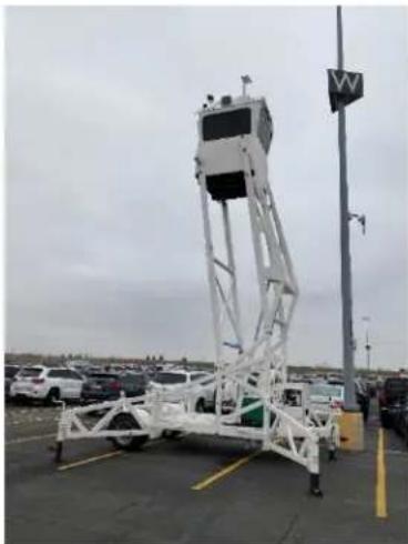
The SkyWatch is a highly configurable, highly mobile, self-powered manned surveillance platform that users can rapidly deploy in both remote and urban environments. The SkyWatch comes in two primary variants, a gasoline model and a diesel model, both of which can be configured with either a one or two-man cab.
When deployed, the SkyWatch provides security officers with an elevated 360^ view of the environment, which can be enhanced with optional spotlights, thermal and visible spectrum cameras, or ground surveillance radar.
NOTE
This manual covers the SkyWatch system only. Specifics on operation and maintenance of surveillance or other payloads and accessories are found in their respective manuals.
Personnel in the officer's compartment control the SkyWatch, raising and lowering the officer's compartment, operating the payloads and the platform's equipment from controls located in the officer's compartment. The SkyWatch can also be raised and lowered from the electrical compartment at the front of the trailer.
2.2 CONFIGURATION
The basic SkyWatch platform consists of a trailer, an officer's compartment fixed to hydraulic lift arms, a generator to supply electrical power for remote operation, dual hydraulic pumps, and various electrical components to support the system's operation. The SkyWatch comes in one and two person models. The table in section 2.5 shows the standard equipment and specifications for each SkyWatch model.
Payloads specified by the customer can include thermal and visible imagers, ground surveillance radar, laser range finding, target illuminators, and wireless radio command and control. Various interfaces, sensors, and device controllers support these payloads and subsystems. The SkyWatch can be configured with a wide variety of sensor and surveillance payloads of various types and capabilities as well as a variety of area lights and surveillance spotlights.
2.3 PLATFORM COMPONENTS
This section covers the common components of the SkyWatch mobile surveillance platforms. Information on optional equipment may be found in the respective manufacturer's operator manuals.
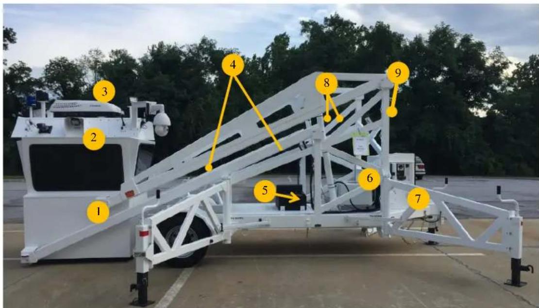
Figure 1: SkyWatch with Gasoline Generator and 1-Man Cab
| PRIMARY PLATFORM COMPONENTS | |
| 1 | Officer's Compartment |
| 2 | Wide area LED Floodlights (4) |
| 3 | 15K Air Conditioner |
| 4 | Hydraulic Lift Arms |
| 5 | Fuel Tank (on trailer deck) |
| 6 | Generator Location (Gasoline) |
| 7 | Electrical Compartment |
| 8 | Hydraulic Cylinders |
| 9 | Solar Panel |
2.4 COMPONENT DESCRIPTIONS
This section provides a general overview of the components on the SkyWatch platform. The components are discussed in detail in later sections of the manual.
OFFICER'S COMPARTMENT
The officer's compartment is the primary surveillance enclosure and provides space for either one or two observers. The officer's compartment also contains controls and indications for raising and lowering the platform, wind speed indicator, generator operation, area observation lights, land mobile radio (if equipped), and displays and controls for any installed payloads.
WIDE AREA FLOOD LIGHTS
Four (4) LED flood lights, each mounted on one side of the observation compartment, provide wide area illumination around the SkyWatch platform for security of the observation crew and the safety of personnel in close proximity to the platform.
AIR CONDITIONER
The air conditioner provides controlled cool air in warm weather.
HYDRAULIC LIFT ARMS
Four (4) hydraulic lift arms, two (2) on each side of the trailer, function to lift and lower the officer's compartment.
FUEL TANK
On the diesel model, the 78-gallon fuel tank is integrated into the deck at the center of the trailer, providing the platform with a generator run time of approximately 111 hours. On the gasoline model, a 20-gallon fuel tank located on the trailer deck behind the generator, provides the gasoline generator with approximately 21 hours of run time.
GENERATOR
The generator provides electrical power to operate the SkyWatch and its optional components while grid power is unavailable or unreliable. The gasoline model has a 5.5KW gasoline generator while the diesel models are equipped with a 6KW diesel generator. Both are located on the rear deck of the trailer behind the electrical compartment.
ELECTRICAL COMPARTMENT
This compartment contains all the operation components of the SkyWatch. These components include the platform's control panel for powering the system and for raising and lowering the cab, circuit breakers, the 9-gallon hydraulic reservoir, the dual hydraulic pump, and all associated wiring and plumbing.
HYDRAULIC CYLINDERS
Two (2) hydraulic cylinders, each a 3.5" diameter hydraulic piston with a 57" stroke, apply hydraulic pressure to the lift struts to raise and lower the officer's compartment. They are located on each side of the platform and are operated by two hydraulic pumps controlled by electronic pump controllers in the officer's compartment.
SOLAR PANEL
The solar panel is used to charge the generator starting battery through a solar charge controller housed in the electrical compartment.
2.5 SKYWATCH SPECIFICATIONS BY MODEL
| Gasoline Standard | Diesel Standard | |
| Height - Transport | 10' 10" | 10' 10" |
| Width - Transport | 8' 2" | 8' 2" |
| Length - Transport | 23' 6" | 23' 6" |
| Height - Cah | 30' 6" | 30' 6" |
| Width - Outriggers | 19' 0" | 19' 0" |
| Approx. Gross | 11,250 | 11,150 |
| Approx. Tongue | 1975 | 1925 |
| 2 5/16 Hitch | Yes | Yes |
| Lunette Eye | optional | optional |
| Wheel/Tire Capacity | 4540 bs. | 4540 lbs. |
| 16K Single Axle 17.5" | Yes | Yes |
| 20 Gallon EVAP Fuel | Yes | N/A |
| 74 Gallon Fuel Tank | N/A | Yes |
| Gasoline Generator | Yes | |
| Diesel Generator | Yes | |
| Generator Run Time | 24 hrs. | 5 days |
| Cab Width - Interior | 4' 7" | 4' 7" |
| Cab Length - Interior | 4' 7" | 4' 7" |
| Cab Height - Interior | 6' 5" | 6' 5" |
| Cab Max Additional | 3500 lbs. | 3500 lbs. |
| Window Type | Tinted Sliding | Tinted Sliding |
| Descent Camera | Yes | Yes |
| Blue Strobe Light | Yes | Yes |
| Digital Wind | Yes | Yes |
| LED Flood Lights (4) | Yes | Yes |
| 15K BTU Air | Yes | Yes |
| Swivel Chair | 1 | 1 |
| Hydraulic Reservoir | 9 Gallon | 9 Gallon |
| Hydraulic Pumps | 2 | 2 |
| AC 9-Gal Hydraulic | Yes | Yes |
| Hydraulic Cylinder | 3.5" | 3.5" |
| Hydraulic Cylinders | 57" | 57" |
| Solar Battery | Yes | Yes |
2.6 PAYLOADS AND OPTIONAL EQUIPMENT
The basic SkyWatch is ideal for deploying a number of options to aid in area surveillance, crowd control, and force protection. SkyWatch is capable of using various payloads to support these missions. The following are common FLIR payloads.
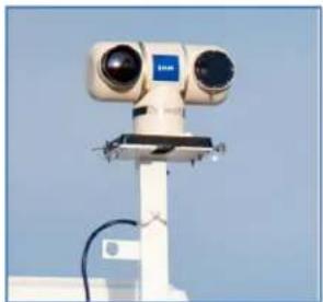
FLIR® RANGER® MS-UC DEFENDIR PTZ CAMERA
The Ranger ^® MS-UC DefendIR is an industry leading mid-range thermal imager utilizing a 640 x 480 array uncooled VOX Thermal detector with and is available in a variety of detector / lens combinations to suit your surveillance needs. The innovative VisionSense ^™ technology offers user-controlled, customized real time mixing and merging of the visible (CCD) camera and the Thermal Imager. The Ranger MS-UC DefendIR is ideally suited for day and night security, surveillance, and DHS/DoD applications. Also includes an 8 Channel FLIR Meridian NVR and Flat Screen Monitor.
natural_image
Exterior view of a surveillance camera mounted on a pole against a clear blue sky (no text or symbols visible)FLIR® PT- SERIES PTZ CAMERAS
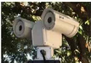
FLIR's PT-Series of HD-IP, multi-sensor pan/tilt cameras bring Thermal and Visible imaging together. The PT-Series' precision pan/tilt mechanism gives you accurate pointing control and provides programmable scan patterns and other features. The PT-Series are available in several Detector and lens specifications to suite your surveillance needs. Also includes an 8 Channel FLIR Meridian NVR and Flat Screen Monitor.
natural_image
Exterior view of a surveillance camera mounted on a tripod outdoors, surrounded by trees (no visible text or symbols)FLIR® DAY/NIGHT PTZ CAMERA
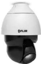
The Day/Night PTZ Camera features a high-speed Pan/Tilt with 30X Optical and 10X Digital Zoom, True Day/Night viewing and the next generation image sensor with FHD 1080P 1920X1080 resolution and up to 200M (650Ft) Night illumination. Includes 2 Cameras, 8 Channel FLIR Meridian NVR and Flat Screen Monitor.
natural_image
Close-up of a white and black FLIR security camera with a black dome-shaped lens (no visible text or symbols)ADDITIONAL FIXED CAMERAS
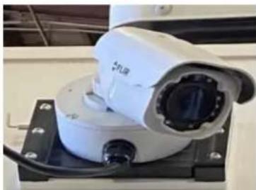
3 Additional FLIR Day/IR staring roof-mounted varifocal 4KUHD, 1256X1440 resolution cameras can now be added to any of the PTZ camera solutions. The cameras feature "Smart-IR Night Vision" allowing the user to see at night out to 30 meters (98 ft).
natural_image
Close-up of a white surveillance camera mounted on a black base with visible wiring (no text or symbols)2.7 OPTIONAL EQUIPMENT AND SERVICES
Some equipment and services are options for your SkyWatch system. These options are explained below. For more information about optional equipment, service plans, and Extended Warranties, contact your FLIR representative.
PUBLIC ADDRESS SYSTEM
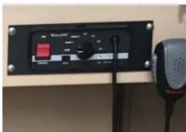
The Whelen PA sound system is a full function Public Service Siren plus radio repeat and Public Address System. It can also be connected to repeat Public Service Radio channels. Installed with two Whelen speakers.
natural_image
Front view of a black electronic device with a red indicator and control panel, connected to a microphone (no visible text or symbols)WIRELESS CONNECTIVITY
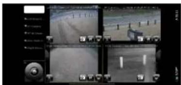
Whether at the Command Center or viewing imagery on a smartphone, tablet, or laptop, we can provide this optional capability to monitor and manage the Video Surveillance system in SkyWatch.
ROOF-MOUNTED SEARCH LIGHTS
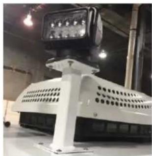
The Ultraviolet and Saltwater resistant search light is controlled by a wired dash mount joystick lever pan and Tilt control. Range of motion is 370° rotation and 135° tilt. This search light provides superior light penetration with state-of-the-art P-Vex™ lens and LED technology. The search light has an 8 degree beam angle, delivering 410,000 candelas and a max beam distance of 4,200 feet.
natural_image
Exterior view of a modern industrial robotic device with control panel and mounted components (no visible text or symbols)SERVICE PLANS
FLIR is dedicated to making sure you get lasting service from your SkyWatch tower. We are always available to help answer questions to ensure you get the most out of your new tower. SkyWatch is already covered under a Limited One Year Warranty which covers the tower itself, along with various Manufacturers' warranties that are in place as well. However, if you want peace of mind beyond the first year, FLIR has developed two low-cost service plans and Extended Warranties to assist you in keeping your SkyWatch tower operational for many years to come. The purpose of these plans is to provide highly responsive customer support and detailed preventive maintenance inspections (PMI) from a FLIR factory trained technician.
natural_image
Exterior view of a white industrial radar or monitoring station with a tower, parked cars, and a pole (no visible text or symbols)3.0 OFFICER'S COMPARTMENT
The officer's compartment provides an environmentally sealed platform for one or two observers and allows 360^ view of the surrounding area from a deployed height of up to 7.6 meters (27 feet at eye level). The interior of the cab can be custom configured with displays and controls for specific missions and payloads; however, standard equipment includes a work surface and chair, controls for raising and lowering the officer's compartment, generator controls, controls for SkyWatch lighting, the digital wind speed display, air conditioning and heating controls, emergency descent controls, radio and/or public address system.
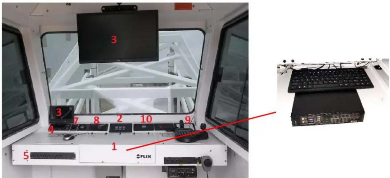
Figure 2: Officer's Compartment Interior
| PRIMARY OFFICER'S COMPARTMENT COMPONENTS | |
| 1 | Main Console (hidden inside compartment) |
| 2 | Lighting Control Panel |
| 3 | Under Cab Monitor & Optional 24" Monitor |
| 4 | 12 VDC, USB and E-Net Outlet |
| 5 | DC Circuit Breaker Panel |
| 6 | AC Controls |
| 7 | Up/Down Momentary Switch |
| 8 | Generator Remote Start and fuel gauge |
| 9 | 120 VAC GFCI Outlets |
| 10 | Digital Windspeed Meter |
3.1 COMPONENT DESCRIPTIONS
This section provides a general overview of the components in the officer's compartment. The components are discussed in detail in later sections of the manual.
MAIN CONSOLE
The main console is the primary workspace for the officer's compartment. The console is located at the front of the compartment. Mounted on the console are controls and indications for the various systems of the SkyWatch. The center of the console is a hinged storage area which is also used as an equipment bay (e.g. DVR, if equipped). A DC circuit breaker panel, 12 VDC outlet, and PA system (if equipped) are mounted to the front of the console.
LIGHTING CONTROL PANEL
The light control panel operates the on/off state of the four flood lights, cabin dome light and the blue strobe light on SkyWatch.
MONITORS
The 7" monitor on the lower left side of the console is standard equipment and is used to view the under-cab camera. The monitor above the console is an optional 24" flat panel screen that comes with optional equipment.
12 VDC, USB AND E-NET OUTLET
The 12 VDC USB outlet allows operators to connect and operate 12 VDC auxiliary devices (e.g. radio or cell phone chargers). An optional E-Net Outlet is available.
DC CIRCUIT BREAKER PANEL
The DC breaker panel, located on the front of the main console, contains between 8 and 11 circuit breakers to protect the various system components. See the circuit breaker table in the appendix for more information.
AC CONTROLS (LOCATED LEFT SIDE ON OVERHEAD PANEL)
The air conditioner controls operate the roof-top air conditioner.
UP/DOWN MOMENTARY SWITCH
The switch is the primary control for raising and lowering the officer's compartment.
GENERATOR REMOTE START AND FUEL GAUGE
Remote start allows the operator to start the generator from inside the cab.
120 VAC GCFI OUTLETS
Two 120 VAC GCFI electrical outlets allow the occupants to operate AC equipment (e.g. network clients, routers, wireless data radio, etc.) in the officer's compartment. One outlet is located on the main console, the other is located inside the main console under an access cover.
DIGITAL WINDSPEED METER
Windspeed meter provides a digital readout on the console panel.
4.0 ELECTRICAL COMPARTMENT
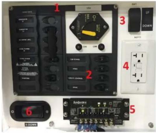
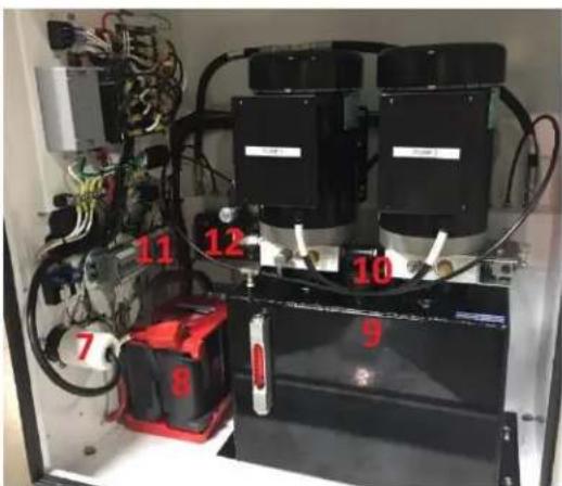
The Electrical Compartment is located at the front of the SkyWatch trailer. The compartment is separated into the Control Panel and the Control Box and contains electrical components, breakers, switches and hydraulic components. There are two doors on the Electrical Compartment: one to access the control box and one to protect components from tampering or unauthorized operation. See Figure 3 (below) for the layout of the components inside the compartment.
natural_image
Interior view of an electrical equipment cabinet with wiring, switches, and a battery unit (no visible text or symbols)Figure 3: Electrical Compartment
| ELECTRICAL COMPARTMENT COMPONENTS | |||
| CONTROL PANEL | CONTROL BOX | ||
| 1 | Input Power Selector Switch Panel | 8 | 12 VDC Generator Start Battery |
| 2 | Circuit Breakers | 9 | Hydraulic Fluid Reservoir |
| 3 | Up/Down Momentary Switch | 10 | Dual Hydraulic Pump #1 and #2 |
| 4 | 120 VAC GFCI Outlet | 11 | Control Panel Wiring |
| 5 | Solar Charge Controller | 12 | Trailer Wiring Control Box |
| 6 | Emergency Down | ||
| 7 | Shore Power Connector | ||
4.1 ELECTRICAL COMPONENT DESCRIPTIONS
This section provides a general overview of the electrical components on the SkyWatch platform. The components are discussed in detail in later sections of the manual.
INPUT POWER SELECTOR SWITCH PANEL
The input power selector breaker panel has two positions used to select input from either external shore power or the SkyWatch on-board generator. UP is for generator and DOWN is for shore power.
CIRCUIT BREAKERS
The circuit breakers are push-pull circuit breakers. From left to right, CB5 (7.5A) protects the solar charge controller; CB6 (7.5A) protects the break-away switch. The 80A generator battery circuit breaker (CB4) is used to isolate the generator battery from the generator. This CB is typically open when the system is in storage.
UP/DOWN MOMENTARY SWITCH
The Up/Down momentary switch is used to raise and lower the officer's compartment from the electrical compartment.
120 VAC GFCI OUTLET
The GFCI outlet on the left electrical panel is used to power auxiliary equipment as needed. It is only operative when the SkyWatch is operating on shore power or when the on-board generator is running.
The solar charge controller is used to provide charging power to the generator battery via the trailer's solar panel. This device is active and continues to charge the battery when the platform is unpowered.
EMERGENCY DOWN
Allows operator to bring down the cab in emergency.
SHORE POWER PLUG
The shore power connector is used to connect the customer supplied shore power to the SkyWatch.
12VDC GENERATOR START BATTERY
The generator battery is a 12 VDC AGM battery used to start the generator. It is recharged by the solar panel and solar charge controller.
HYDRAULIC PUMP #1 & #2
The hydraulic pumps move hydraulic fluid into the hydraulic cylinders to raise the lift struts and pressurize the system to hold the lift struts in place. Hydraulic pump #1 is on the left, pump #2 is on the right.
HYDRAULIC FLUID RESERVOIR
The 9 gallon (34 liter) hydraulic fluid reservoir provides hydraulic fluid for the system during operation and provides fluid storage while the system is shut down. The reservoir is also used as the return from the hydraulic system weep tee and the emergency hydraulic dump valve.
CONTROL PANEL WIRING
The wiring panel and bus is the main wiring bus for the SkyWatch.
TRAILER WIRING CONTROL BOX
Wiring for the 12V trailer system.
PROXIMITY SWITCH
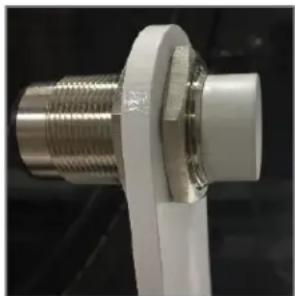
The proximity switch, mounted on a welded trailer bracket beside the electrical compartment on the lower left (street side), is used to disengage hydraulic pump #2 when the right (street side) hydraulic cylinder reaches 90% of its fully deployed stroke. This prevents hydraulic system overpressure and reduces jerking of the officer's compartment when it reaches its fully deployed height.
natural_image
Close-up of a white plastic connector with threaded metal fitting (no text or symbols visible)Figure 4: Proximity Switch
5.0 ELECTRICAL SYSTEM
The SkyWatch operates on 230 VAC grid power, or two 120 VAC lines when using the platform's on-board generator.
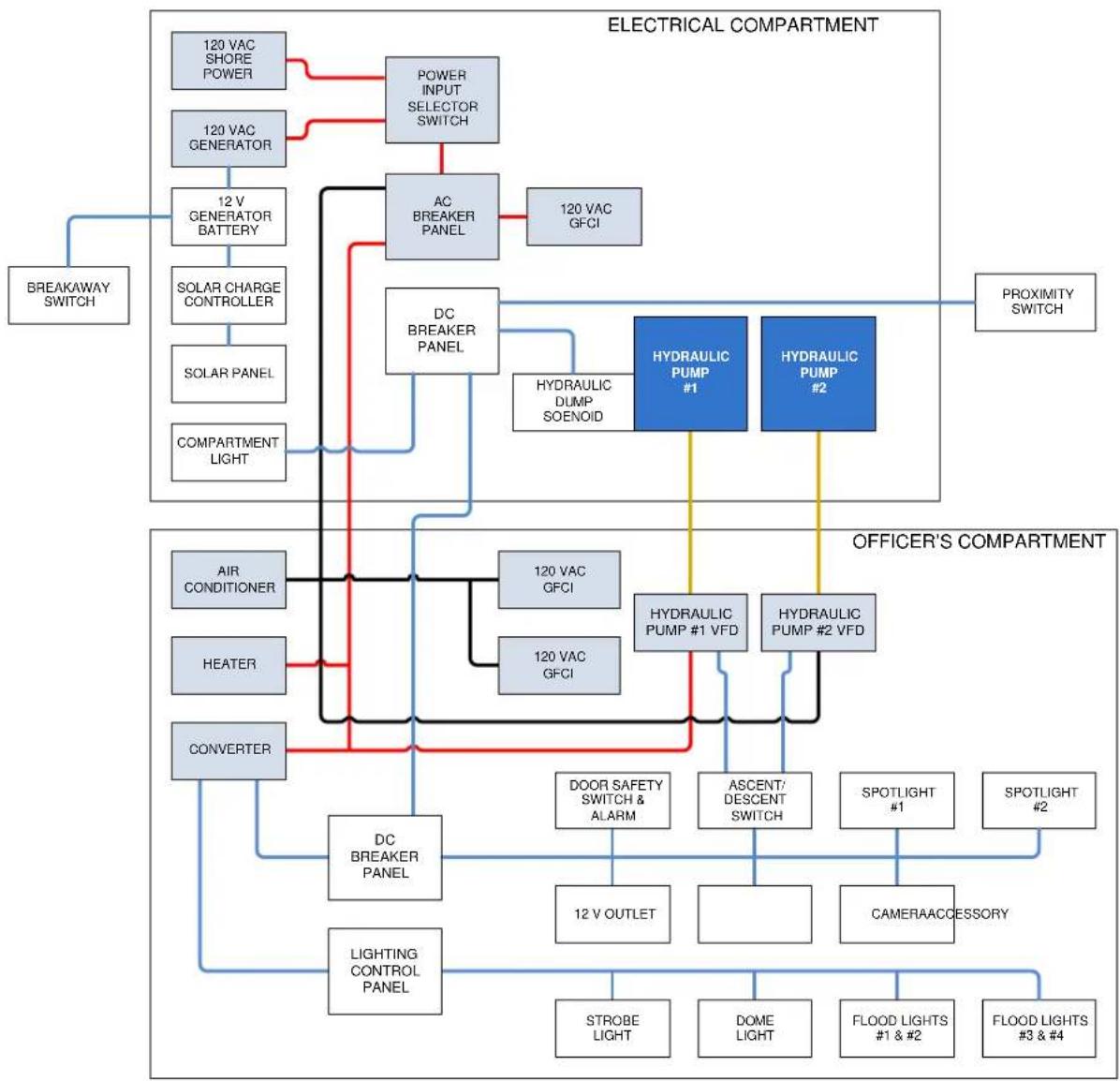
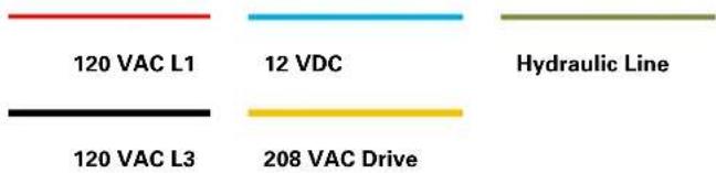
In normal operation, 230 VAC from shore power or two 120 VAC feeds come from the onboard generator to a transfer switch used to switch the load between the shore or generator power. Shore power is then routed to the AC breaker panel in the electrical compartment, where it is split into two 120 VAC lines, L1 and L3. The generator dual 120 V power outputs are fed directly to the L1 and L3 generator circuit breakers. One L1 line from the AC breaker panel provides power to the GFCI convenience outlet in the electrical compartment for the connection of auxiliary devices.
L1 and L3 are routed from the electrical compartment to the officer's compartment. L1 provides AC power to the heater, AC/DC converter, and hydraulic pump motor #1 VFD. L3 provides power to the air conditioner, two GFCI outlets, and hydraulic pump motor #2 VFD.
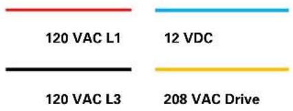
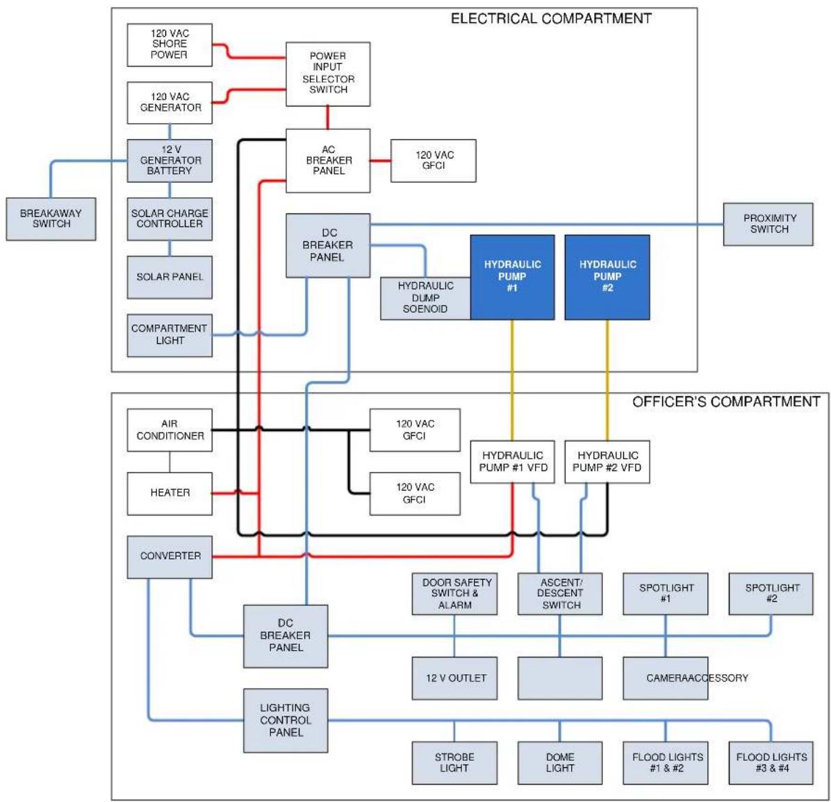
120 VAC power from L1 is converted at the AC/DC converter into 12 VDC and routed to the DC circuit breaker and the lighting control panel. The DC power distribution further feeds a 12 VDC auxiliary outlet, DC breaker and the lighting control panels. The 12 VDC breaker panel provides power to the door safety switch, down alarm, ascent/descent switches, the camera (if installed), the auxiliary 12 VDC receptable and other electronic components. The lighting control panel provides power to the strobe light, officer's compartment's dome light, and flood lights 1 and 2, 3 and 4. The 12 V system in the operator's compartment is not part of or connected to the generator starting battery and charging systems.
The SkyWatch 12 VDC battery operated generator starting system is used to start the generator and operate the trailer brakes in a breakaway condition. The system has a solar panel and internal generator charge controller that keeps the battery charged. The generator onboard charging system only operates when the generator is on, and the solar panel only charges the battery when the generator is off. The solar panel needs direct sunlight to charge the battery.
When the SkyWatch is operating on shore power (external 120 VAC) and the shore power is interrupted, the generator can be started to provide 120 VAC. When operating on shore power, the solar charger is the only source for charging the Start Battery. If the unit is stored indoors, we recommend a fully automatic float charger be connected to the Start Battery terminals.
Controls for starting and stopping the generator are located both in the officer's compartment and at the generator.
flowchart
graph TD
    subgraph ELECTRICALCOMPARTMENT
        A["120 VAC SHORE POWER"] --> B["POWER INPUT SELECTOR SWITCH"]
        C["120 VAC GENERATOR"] --> D["AC BREAKER PANEL"]
        E["BREAKAWAY SWITCH"] --> F["SOLAR CHARGE CONTROLLER"]
        G["SOLAR PANEL"] --> H["COMPARTMENT LIGHT"]
        I["12 V GENERATOR BATTERY"] --> J["DC BREAKER PANEL"]
        K["120 VAC GFCI"] --> L["HYDRAULIC DUMP SOENOID"]
        M["AIR CONDITIONER"] --> N["120 VAC GFCI"]
        O["HEATER"] --> P["120 VAC GFCI"]
        Q["CONVERTER"] --> R["DC BREAKER PANEL"]
        S["DOOR SAFETY SWITCH & ALARM"] --> T["ASCENT/DESCENT SWITCH"]
        U["12 V OUTLET"] --> V["CAMERA ACCESSORY"]
        W["STROBE LIGHT"] --> X["DOME LIGHT"]
        Y["FLOOD LIGHTS #1 & #2"] --> Z["FLOOD LIGHTS #3 & #4"]
    end

    subgraph OFFICER'SCOMPARTMENT
        AA["HYDRAULIC PUMP #1"] --> AB["HYDRAULIC PUMP #2"]
        AC["HYDRAULIC PUMP #1 VFD"] --> AD["HYDRAULIC PUMP #2 VFD"]
        AE["120 VAC GFCI"] --> AF["HYDRAULIC PUMP #1 VFD"]
        AG["120 VAC GFCI"] --> AH["HYDRAULIC PUMP #2 VFD"]
        AI["DOOR SAFETY SWITCH & ALARM"] --> AJ["ASCENT/DESCENT SWITCH"]
        AK["12 V OUTLET"] --> AL["CAMERA ACCESSORY"]
        AM["STROBE LIGHT"] --> AN["DOME LIGHT"]
        AO["FLOOD LIGHTS #1 & #2"] --> AP["FLOOD LIGHTS #3 & #4"]
    end

    B --> D
    D --> F
    F --> H
    H --> I
    I --> J
    J --> K
    K --> AL
    AL --> AM
    AL --> AN
    AL --> AO
    AL --> AP
    AL --> AQ
    AL --> AR
    AL --> AS
    AL --> AT
    AL --> AU
    AL --> AV
    AL --> AW
    AL --> AX
    AL --> AY
    AL --> AZ
    AL --> BA
    AL --> BB
    AL --> BC
    AL --> BD
    AL --> BE
    AL --> BF
    AL --> BG
    AL --> BH
    AL --> BI
    AL --> BJ
    AL --> BK
    AL --> BL
    AL --> BM
Figure 5: AC System Diagram
flowchart
graph TD
    subgraph ELECTRICALCOMPARTMENT
        A["120 VAC SHORE POWER"] --> B["POWER INPUT SELECTOR SWITCH"]
        C["120 VAC GENERATOR"] --> D["AC BREAKER PANEL"]
        E["BREAKAWAY SWITCH"] --> F["SOLAR CHARGE CONTROLLER"]
        F --> G["SOLAR PANEL"]
        G --> H["COMPARTMENT LIGHT"]
        I["12 V GENERATOR BATTERY"] --> D
        J["SOLAR PANE"] --> H
    end

    subgraph OFFICER'SCOMPARTMENT
        K["AIR CONDITIONER"] --> L["HEATER"]
        M["CONVERTER"] --> N["DC BREAKER PANEL"]
        O["DOOR SAFETY SWITCH & ALARM"] --> P["12 V OUTLET"]
        Q["ASCENT/DESCENT SWITCH"] --> R["12 V OUTLET"]
        S["CAMERA ACCESSORY"] --> T["STROBE LIGHT"]
        U["DOME LIGHT"] --> V["DOME LIGHT"]
        W["FLOOD LIGHTS #1 & #2"] --> X["FLOOD LIGHTS #3 & #4"]
    end

    B --> D
    D --> F
    F --> H
    H --> N
    N --> O
    O --> P
    P --> Q
    Q --> R
    R --> S
    S --> X
    T --> X
    X --> Y["STROBE LIGHT"]
    X --> Z["DOME LIGHT"]
    X --> AA["FLOOD LIGHTS #1 & #2"]
    X --> AB["FLOOD LIGHTS #3 & #4"]
    K --> AD["HYDRAULIC PUMP #1"]
    K --> AE["HYDRAULIC PUMP #2"]
    AD --> AF["HYDRAULIC DUMP SOENOID"]
    AE --> AG["HYDRAULIC PUMP #1 VFD"]
    AE --> AH["HYDRAULIC PUMP #2 VFD"]
    AD --> AI["PROXIMITY SWITCH"]
    AE --> AJ["PROXIMITY SWITCH"]
Figure 6: DC System Diagram
6.0 HYDRAULIC SYSTEM
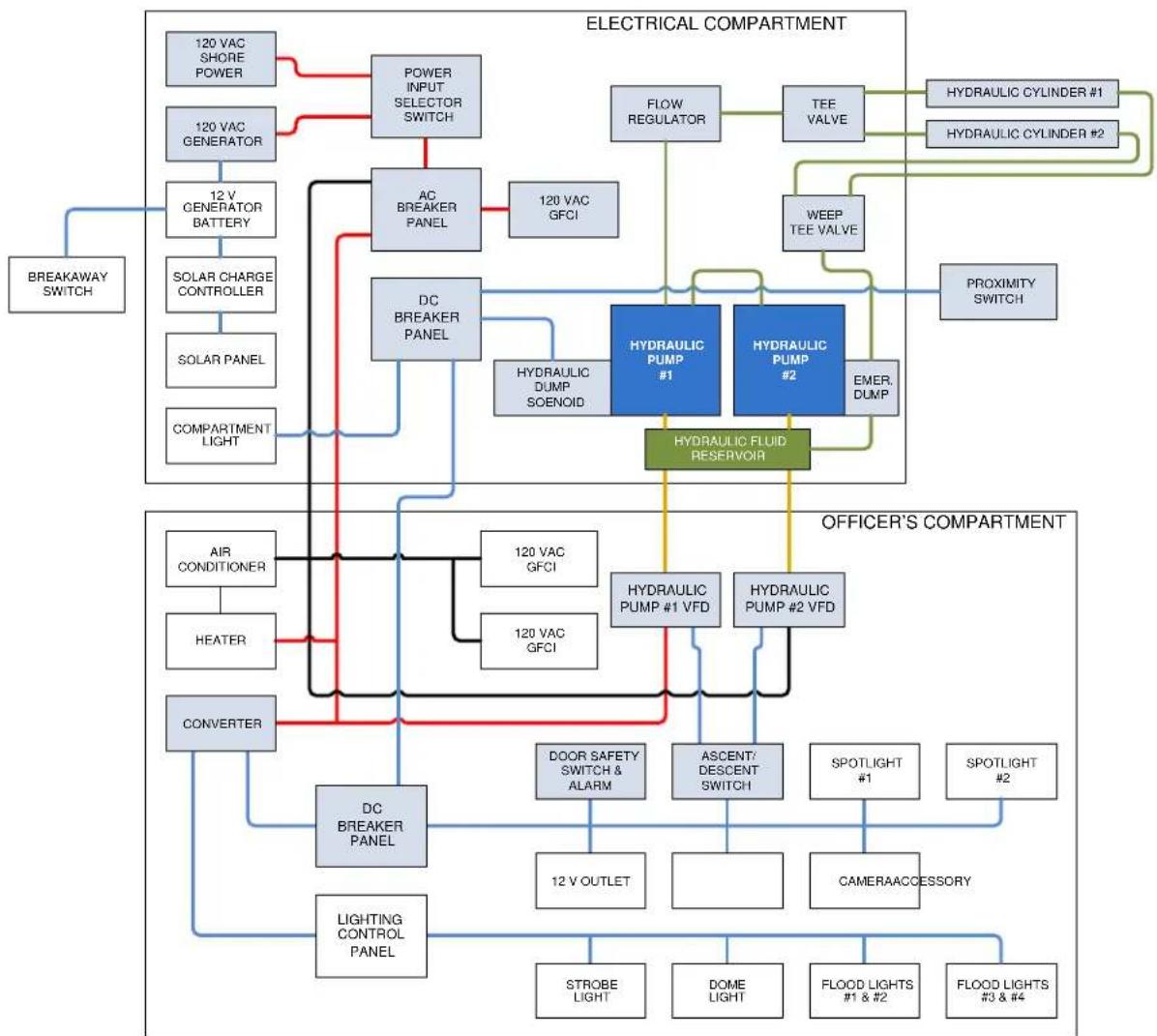
The hydraulic system on the SkyWatch is used to raise and lower the officer's compartment. The system uses two hydraulic pumps to operate two 3.5" hydraulic cylinders, each with a 57" stroke, which move the hydraulic lift struts attached to the officer's compartment. The hydraulic system is controlled by two hydraulic pump controllers in the officer's compartment. The primary lift control is a momentary switch located in the officer's compartment. A second lift control, the up/down momentary switch located in the electrical compartment, can be used to operate the system from the ground.
Under normal operation when the officer's compartment is stowed, the hydraulic system is charged using the hydraulic fluid reservoir located in the electrical compartment under the two hydraulic pumps.
The hydraulic pump controls 1 and 2 (HPC 1 & 2) in the officer's compartment, powered by 120 VAC from system's power source, routed through the AC breaker panel in the equipment box, control the operation of the hydraulic pumps in the equipment box. Commands to the HPCs come from the 12 VDC ascent/descent switches. The primary ascent/descent switch is located in the officer's compartment, and an auxiliary ascent/descent switch is located in the equipment box.
When the command is given to raise the officer's compartment from either the primary or auxiliary ascent/descent switch, 208 VAC is routed through hydraulic pump controls 1 and 2 in the officer's compartment to hydraulic pumps 1 and 2 in the equipment box. The hydraulic pumps move hydraulic fluid from the hydraulic reservoir under the pumps into the hydraulic cylinders to raise the struts. Once the officer's compartment is deployed to the commanded height, pressure is maintained by the hydraulic pumps to hold the lift struts in position.
When the command is given to lower the officer's compartment from either the primary or auxiliary ascent/descent switch, a 12 VDC dump solenoid is activated to release hydraulic fluid from the hydraulic cylinders back into the reservoir, lowering the officer's compartment.
A proximity switch, located on the lower left side (street side) in front of the 57" cylinders, serves to control pressure to protect the hydraulic system. When the hydraulic cylinders reach 90% of their full extension, the proximity switch senses the position of the left (street side) hydraulic cylinder and shuts down hydraulic pump #2. This reduces the operational pressure of the hydraulic system, preventing over-pressure at the end of hydraulic cylinders' stroke, and reduces sudden jerking of the officer's compartment when it reaches its full deployment height and end of ascent travel.
Should the hydraulic seals become damaged or worn over time, recovery of any leaking hydraulic fluid is facilitated by "weep" lines attached to each cylinder, which return any weeping or excess hydraulic fluid to the reservoir.
An electrically activated safety switch on the officer's compartment door prevents operation of the hydraulic system when the door is not closed and secured. An emergency lowering system allows occupants of the officer's compartment to lower the compartment should the hydraulic system become inoperable.
Should the hydraulic system fail to operate (electrical power failure, failure of the hydraulic pumps, etc.) the pressure in the hydraulic cylinders will maintain the position of the officer's compartment. An emergency descent handle is located inside the officer's compartment and allows the operator to lower the officer's compartment when the electrical system has failed. Pushing the emergency descent handle towards the right manually activates the emergency release dump valve, allowing the hydraulic fluid in the hydraulic cylinders to return to the hydraulic reservoir thus lowering the officer's compartment. Descent time of the officer's compartment from full height to the ground is approximately 90 seconds.
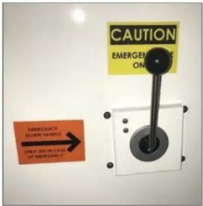
Figure 7: Emergency Descent Handle
flowchart
graph TD
    subgraph ELECTRICALCOMPARTMENT
        A["120 VAC SHORE POWER"] --> B["POWER INPUT SELECTOR SWITCH"]
        C["120 VAC GENERATOR"] --> D["AC BREAKER PANEL"]
        E["12 V GENERATOR BATTERY"] --> D
        F["SOLAR CHARGE CONTROLLER"] --> D
        G["SOLAR PANEL"] --> H["DC BREAKER PANEL"]
        I["COMPARTMENT LIGHT"] --> H
        J["BREAKAWAY SWITCH"] --> K["HVRAULIC PUMP #1"]
        K --> L["HYDRAULIC PUMP #2"]
        M["FLOW REGULATOR"] --> N["TEE VALVE"]
        O["WEEP TEE VALVE"] --> P["PROXIMITY SWITCH"]
        Q["HYDRAULIC CYLINDER #1"] --> R["HVRAULIC CYLINDER #2"]
    end
    subgraph OFFICER'SCOMPARTMENT
        S["AIR CONDITIONER"] --> T["HEATER"]
        U["CONVERTER"] --> V["DC BREAKER PANEL"]
        W["LIGHTING CONTROL PANEL"] --> X["STROBE LIGHT"]
        Y["DOOR SAFETY SWITCH & ALARM"] --> Z["ASCENT/ DESCENT SWITCH"]
        AA["12 V OUTLET"] --> AB["CAMERA ACCESSORY"]
        AC["DOME LIGHT"] --> AD["FLOOD LIGHTS #1 & #2"]
        AE["SPOTLIGHT #1"] --> AF["CAMERAACCESSORY"]
        AG["SPOTLIGHT #2"] --> AH["CAMERAACCESSORY"]
        AI["HYDRAULIC PUMP #1 VFD"] --> AJ["HYDRAULIC PUMP #2 VFD"]
        AK["HYDRAULIC DUMP SOENOID"] --> AL["HYDRAULIC FLUID RESERVOIR"]
    end
    B --> D
    D --> H
    H --> K
    K --> L
    L --> N
    N --> O
    O --> P
    P --> R
    R --> S
    S --> T
    T --> U
    U --> V
    V --> X
    X --> Y
    Y --> Z
    Z --> AA
    AA --> AB
    AB --> AC
    AC --> AD
    AD --> AE
    AE --> AF
    AF --> AG
    AG --> AH
    AH --> AI
Figure 8: Hydraulic System
7.0 POWER GENERATION
7.1 SHORE POWER
Primary power for operating U.S. variants of the gasoline and diesel models is provided by a 230 VAC 50 A 60 Hz shore power connection located on the right side (street side) of the electrical compartment. Shore power may be either grid power or an external generator. Foreign models are powered by 230 VAC 50 A 50 Hz single phase shore power.
The shore power port is a 3-pin male connector that allows the connection of a shore power harness.
The shore power harness connects to the shore power connector using an environmentally sealed 3-pin female socket connector. 230 VAC 50 A 60 Hz supplied from the external power source goes through the shore power harness and into the equipment box where it provides AC power for the System.
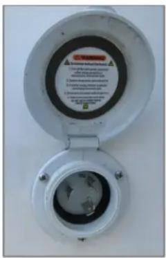
Figure 9: Shore Power Connector
Use a heavy duty (12 gauge or heavier) grounded extension cord to connect the harness to grid power. The line should be a dedicated (single use) 230 V circuit rated at 50 A or better.
NOTE
Shore power is required when operating the SkyWatch tower indoors.
MANAGING EUROPEAN POWER
A power inverter system can be used to utilize European power sources for the SkyWatch.
- Configure the circuit breaker line-up for Shore Power use.
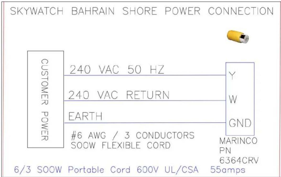
- Connect the 240 VAC / 50 HZ (single wire) Shore Power connector to the SkyWatch input plug, located on the lower left side of the inverter/lift pump cabinet.
- On the Inverter External Control Panel, mounted inside the inverter/lift pump cabinet's circuit breaker panel, set the inverter control switch to "Power On."
- If the shore power is supplying power, the Green LED for "Battery charger" will be illuminated.
line
| Power Supply | Label | | ------------ | ----------------- | | 240 VAC 50 Hz | Y | | 240 VAC RETURN | W | | EARTH | GND | | #6 AWG / 3 CONDUCTORS SOOW FLEXIBLE CORD | MARINCO PN | | 6/3 SOOW Portable Cord 600V UL/CSA | 6364CRV 55amps |7.2 DIESEL GENERATOR MODELS
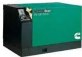
On diesel models of the SkyWatch, an Onan HDKAV diesel-powered generator is used to provide primary electrical power generation for the SkyWatch if shore power is unavailable or unreliable. The diesel generator is located on the rear deck behind the equipment box. The diesel generator is a 719cc water-cooled 4-cycle diesel engine that drives a permanent-magnet alternator capable of generating up to 6000 watts of power.
natural_image
Exterior view of a green and black industrial machine (no visible text or symbols)Figure 10: SkyWatch Diesel
Various controls on the generator operator's panel provide operation and indication of the generator's status. See Section 8.0, Controls and Indications, for more information.
Power to start the generator is provided by the 12 VDC system battery located in the equipment box, which is recharged by a small solar array mounted on the support bar above the equipment box.
The generator is fueled by a 295-liter (78 US gallons) fuel tank, integrated into the deck at the center of the platform that stores fuel for approximately 111 hours (4 1/2 days) of operation at full generator load or 195 hours (8 1/8 days) at half-load. Fuel for the generator is No. 2 diesel fuel (ASTM-D2). An electric fuel gauge on the platform's power control panel provides indication of fuel level. Indication of fuel level is not available until the generator is running. Generator operation is controlled by controls in the officer's compartment or by using the generator's operator panel. The generator's fuel gauge is located in the officer's compartment.
| DIESEL GENERATOR SPECIFICATIONS | |
| Size (L x W x H) | Length 36.35 in (923.2 mm), width 24.23 in (615.4mm), height 22.28 in (565.9 mm) |
| Weight | 420 lbs. (190.9 kg), wet |
| Engine | 4-cycle, liquid-cooled diesel engine, 3 cylinders, inline vertical |
| Displacement | 43.88 in _3 (719 cm _3 ) |
| Compression Ratio | 23:1 |
| Oil Capacity (w/ filter) | 2.8 qt (2.61 L) |
| Cooling System Capacity | 4 qt (4.2 L) |
| Fuel | ASTM 2-D (No. 2 diesel fuel) |
| Fuel Consumption | No Load: 0.21 G/hr (0.79 L/hr) |
| Half-Load: 0.40 G/hr (1.50 L/hr) | |
| Full Load: 0.70 G/hr (2.65 L/hr) | |
| Electrical Generator | 2-bearing, 2-pole rotating field, Direct Drive inverter. |
| RPM (max) | 3600 R/MIN: 16.6 hp SAE net intermittent |
| Power | 6000 W |
| Voltage @ 60 Hz | 120 V 1-Ph, Dual output. |
| Current | 50 A |
| Circuit Breaker | (1) 2-pole, 30 A |
^1 Oil recommendation is based upon a deployment environment with temperature ranges from freezing to temperatures higher than 38^ C ( 100^ F). Refer to the Cummins Onan HDKAV Generator Operator Manual for oil options best suited for your area of operations.
Generator operating instructions, considerations, safety information, and limitations are found in the Cummins Onan HDKAV Generator Operator Manual.
7.3 GASOLINE GENERATOR MODELS
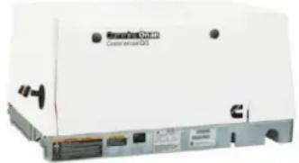
On gasoline models of the SkyWatch, a 5.5HGJAD gasoline generator is used to provide primary electrical power generation for the SkyWatch should shore power be unavailable or unreliable. The gasoline generator is located directly behind the electrical compartment.
The gasoline generator is a 653cc carbureted air-cooled 4-cycle gasoline engine that drives a revolving field 2-pole self-excited AC alternator capable of generating up to 5500 Watts of power.
natural_image
Front view of a white electronic device labeled 'Smartout' with ports and connectors (no readable text beyond branding)SkyWatch Gasoline Generator
Various controls on the generator operator's panel provide operation and indication of the generator's status. See Section 8.0, Controls and Indications, for more information.
Power to start the generator is provided by the 12 VDC battery located in the equipment box, which is recharged by an internal charging system when running, and a small solar panel mounted on the support bar above the equipment box when not running.
The generator is fueled by a 75.7-liter (20 US gallons) fuel tank mounted on the deck beside the generator that stores fuel for approximately 21 hours (.875 days) of operation at full generator load and 33 hours (1.38 days) at half-load. The recommended fuel for the gasoline generator is unleaded gasoline with a minimum octane rating of 87. An electric fuel gauge on the platform's power control panel provides indication of fuel quantity. Note that when the master switch is OFF, indication of fuel quantity is not available.
Generator operation is controlled by controls in the officer's compartment or by using the generator's operator panel. The generator's fuel gauge is located in the officer's compartment.
| GASOLINE GENERATOR SPECIFICATIONS | |
| Size (L x W x H) | 85.3 x 56.3 x 42.5 cm (33.6 x 22.2 x 16.7 in) |
| Weight | 132 kg (290 lbs.) |
| Engine | 2-cylinder air cooled 90° V-twin normally aspirated 4-stroke |
| RPM | 2400 |
| Displacement | 653 cc |
| Compression Ratio | 8:1 |
| Oil Capacity (w/ filter) | 1.9 liter (2 US quarts) SAE 30 or 15W-40 ^1 |
| Cooling System Capacity | 500 ft./min. |
| Fuel | ASTM 2-D (No. 2 diesel fuel) |
| Fuel Consumption | Half-Load: 0.60 G/hr (2.3 L/hr) |
| Full Load: 0.95 G/hr (3.6 L/hr) | |
| Electrical Generator | 2-bearing, 2-pole rotating field, Poly V Belt drive |
| RPM | 3600 |
| Power | 5500 W |
| Voltage @ 60 Hz | 120 V 1-Ph |
| Current | 45.8 A |
| Circuit Breaker | 2-pole 30 A |
^1 Oil recommendation is based upon a deployment environment with temperature ranges from freezing to temperatures in excess of 38^ C ( 100^ F). Refer to the Cummins Onan QC-5500 Gasoline Generator Operator Manual for oil options best suited for your area of operations.
Generator operating instructions, considerations, safety information, and limitations are found in the Cummins Onan 5.5HGJAD Gasoline Generator Operator Manual.
8.0 CONTROLS AND INDICATIONS
This section describes the various SkyWatch system controls and their operation, as well as system indications.
8.1 OFFICER'S COMPARTMENT
Controls and indications in the officer's compartment provide personnel with the ability to fully operate the SkyWatch systems and any installed payloads.
LIGHTING CONTROL PANEL
The compartment's lighting control panel is located at the center of the compartment's control console and provides control for the SkyWatch officer compartment dome light, the exterior strobe light and four wide area floodlights.
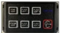
Figure 11: Lighting Control Panel
To activate a light from this panel, press the button for the desired device which will be illuminated when active. Press the button a second time to de-select the device.
An error, such as a blown fuse, will result in an audible alarm and the affected button for the circuit will blink.
UP/DOWN MOMENTARY SWITCH
The switch controls, located to the left of the main panel, are used to raise and lower the officer's compartment.
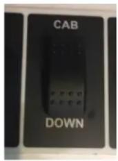
Figure 12: Up/Down Momentary Switch
GENERATOR START/STOP CONTROL
The generator start/stop control is located on the main console to the left of the main panel. A light on the control toggle indicates generator operation (steady on), or various error conditions. A meter displays total hours of generator operation for fueling and maintenance purposes.
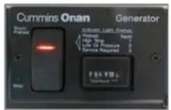
Figure 13: Generator Start/Stop Control
FUEL GAUGE
The gauge located on the left of the main console gives visual indication of the generator's fuel state. The generator must be operating to read fuel level. The gauge's backlight indicates that there is power to the 12 VDC system. If the gauge is not illuminated, there will be no fuel reading.
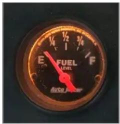
Figure 14: Fuel Gauge
WIND SPEED INDICATOR
An indicator on the main console shows wind speed in order to plan for deployment. The wind meter takes data from an anemometer located on the top of the officer's compartment. The display shows windspeed in Miles Per Hour (Mph).
The maximum recommended sustained wind speed for operation of the SkyWatch is 60 Mph (96 Km).
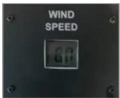
Figure 15: Wind Speed Indicator
AIR CONDITIONER CONTROLS
Air conditioner controls are located on the interior upper left roof panel and is used to operate the platform's air conditioner. As sizes and types of air conditioners used vary with platform configuration and options, refer to the air conditioner's operating manual for instructions. To prevent electrical system overload, a relay switch automatically turns off the air conditioner when the tower is ascending.
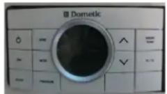
Figure 16: Air Conditioner Controls
HEATER CONTROL
The heater controls are located on side of the heater, mounted on the left wall of the compartment. A simple rotary control is used to turn the system on and off and set the temperature and blower speed. Refer to the heater's operating manual for more information. The Heater must be OFF when ascending to prevent electrical system overload; some newer towers may have a relay switch that automatically turns off the heater when the tower is ascending.
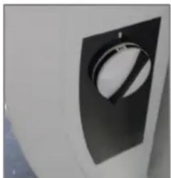
natural_image
Close-up of a white industrial machine dial with a black tab (no visible text or symbols)Figure 17: Heater Control
EMERGENCY DESCENT HANDLE
The emergency descent handle is used to lower the officer's compartment in an emergency should the hydraulic system become inoperative (e.g. power failure). It is located on the left wall of the compartment.
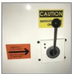
Figure 18: Emergency Descent Handle
OPTIONAL PUBLIC ADDRESS SYSTEM
The public address system is located on the front of the main console on the right side. The system has a microphone for making verbal commands outside of the SkyWatch, and also has a multimode siren function (horn, yelp, wail).
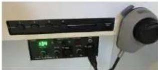
natural_image
Interior view of a room with electronic equipment and a wall-mounted device (no visible text or symbols)Figure 19: PA System
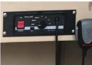
Figure 20: PA System
DC CIRCUIT BREAKER PANEL
The DC breaker panel, located on the front of the main console and containing between 8 and 11 circuit breakers, provides protection for the various system components. See the breaker table in the appendix for more information.
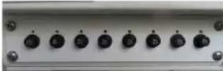
Figure 21: DC Breaker Panel
8.2 ELECTRICAL COMPARTMENT
Controls in the electrical compartment provide personnel with the ability to fully operate the SkyWatch systems from the ground.
POWER INPUT POWER SELECTOR SWITCH
The input power selector breaker panel has two positions used to select power source for the SkyWatch. Selections include SHORE POWER, which is external 230 VAC grid power typically used
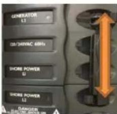
Figure 22: Power Input Selector Switch
to power the platform, or GENERATOR, which selects the platform's on-board generator. To select a power source, slide the breaker bar up or down to desired requirement and then turn breaker on.
UP/DOWN MOMENTARY CONTROL
The Up/Down momentary control is used to raise and lower the officer's compartment from the electrical compartment. Note that there is no safety switch on this control.
The door to the officer's compartment must be closed for the hydraulic system to operate.
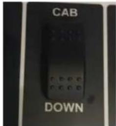
Figure 23: Up/Down Momentary Control
Status lights on the solar charge controller provide visual indication of the function of the charge controller and battery state of charge.
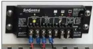
natural_image
Front view of a SunCoAvers 6 electronic device with multiple ports and indicator lights (no readable text or symbols)Figure 24: Solar Charge Controller Indications
PROXIMITY SWITCH
The proximity switch is located on the lower left side (street side) in front of the 57" hydraulic cylinders. It is used to disengage hydraulic pump #2 when the right hydraulic cylinder reaches 90% of its fully deployed stroke to control hydraulic system overpressure and reduce jerking of the officer's compartment when it reaches its fully deployed height.
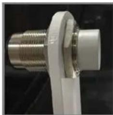
natural_image
Close-up of a metallic mechanical connector with threaded shaft and flange (no visible text or symbols)Figure 25: Proximity Switch
8.3 DIESEL GENERATOR CONTROL PANEL
The operator's panel on the generator provides controls and indications for operating the diesel-powered generator located behind the electrical compartment. The operator's panel is located on the left side (street side) of the generator.
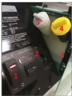
Figure 26: Diesel Generator Operator's Panel
| GENERATOR OPERATOR'S PANEL COMPONENTS | |
| 1 | Control Switch and Status Light |
| 2 | 30 Amp Circuit Breaker |
| 3 | Coolant Pressure Cap |
| 4 | Oil Fill Cap and Dipstick |
| 5 | Coolant Level Indicator |
CONTROL SWITCH AND STATUS LIGHT
The control switch is used to start and stop the generator and prime the engine's fuel system. The status light provides indication of system status: Continuously on during normal operation, system fault indication through blinking codes (refer to the Cummins Onan Generator Operator Manual).
30 AMP CIRCUIT BREAKER
The 30 amp dual circuit breaker protects the AC output of the generator.
GENERATOR RUN TIME METER
The generator hour meter provides visual indication of the number of hours the generator has run. This is important for maintenance intervals.
COOLANT PRESSURE CAP
The coolant pressure cap is located under this access plate. The pressure cap covers and provides access to the coolant refill tube.
OIL FILL CAP AND DIPSTICK
The oil fill cap has an integrated dipstick for checking the generator's oil level. It is located under a latching cover on the generator operator's panel.
COOLANT LEVEL INDICATION
A label alongside the semi-transparent coolant recovery tank provides visual indication of the minimum and maximum allowable coolant levels. DO NOT OVERFILL: the generator will expel excess Coolant.
For more information on using the generator operator's panel and generator operation, limitations, and maintenance, see the Cummins Onan Generator Operator Manual.
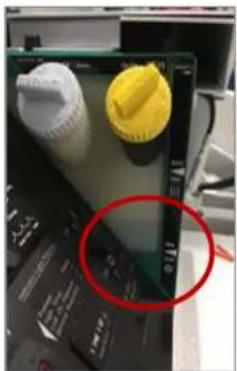
natural_image
Close-up of a computer monitor with three accessories (no visible text or symbols)Figure 27: Diesel Generator Coolant Level
8.4 GASOLINE GENERATOR SYSTEM COMPONENTS
The operator's panel on the generator provides controls and indications for operating the gasoline-powered generator located behind the electrical compartment. The operator's panel is located on the left side (street side) of the generator.
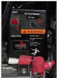
| GASOLINE GENERATOR OPERATOR'S PANEL COMPONENTS | |
| 1 | Control Switch & Status Light |
| 2 | 30 Amp Circuit Breakers |
| 3 | Generator Run Time Meter |
Figure 28: Gasoline Generator Operator's Panel
CONTROL SWITCH AND STATUS LIGHT
The control switch is used to start and stop the generator and prime the gasoline engine's fuel system. The status light provides indication of system status: continuously on during normal operation; and provides system fault indication through blinking codes (refer to the Cummins Onan Generator Operator Manual).
30 AMP CIRCUIT BREAKER
A Dual circuit breaker protects the AC power output of the generator.
GENERATOR RUN TIME METER
The generator hour meter provides visual indication of the number of hours the generator has run. This is important for maintenance intervals.
For more information on using the generator operator's panel and generator operation, limitations, and maintenance, see the Cummins Onan Generator Operator Manual.
9.0 TOWING THE SKYWATCH
9.1 VEHICLE REQUIREMENTS
This section describes the minimum requirements needed to safely tow the SkyWatch mobile surveillance platform. Along with these requirements, check with your state and local authorities to verify that the vehicle and tow equipment meet their requirements.
| SkyWatchTower Model | Ball Size | Gross Weight | Tongue Weight |
| Gasoline | 2 5/16" | 11,250 lbs. | 1,975 lbs. |
| Standard Diesel | 2 5/16" | 11,150 lbs. | 1,925 lbs. |
Refer to chart above based on model. Please use the following guidelines when selecting and configuring a tow vehicle:
All SkyWatch systems are equipped with electric brakes. The electric brake controller is generally included with factory towing packages on all Pickup trucks. If a controller was not included with the vehicle, Aftermarket Brake controllers are available.
OUTSIDE REAR VIEW MIRRORS
Must be wide enough to see the rear corners of the SkyWatch trailer (approximately 24 feet from the bumper of the tow vehicle).
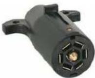
7-WAY ELECTRICAL RECEIVER PLUG
For turn signals, running lights, brake lights and electric brakes.
9.2 UNCOUPLING THE SKYWATCH FROM TOW VEHICLE
The SkyWatch is equipped with an easily operated ball coupler. It is recommended that you become familiar with this section before attempting to couple or uncouple your SkyWatch. Failure to do so may result in personal injury, death, or damage to the unit.
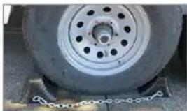
- Chock one wheel on each side, using the wheel chocks provided.
- Disconnect the 7-pin connector taillight hookup, remove safety chains and remove the breakaway brake cable from tow vehicle.
- Release the jack foot. Turn the tongue jack handle clockwise until the foot locks and touches the ground.
- Release the ball coupler, remove the coupler's safety pin, then move the handle out and towards the tow vehicle.
- Return to the tongue jack and continue to rotate the handle (clockwise) until the coupler is released and clear from the hitch.
- Drive tow vehicle away slowly from the SkyWatch Tower.
9.3 COUPLING THE SKYWATCH TO TOW VEHICLE
- Make sure the trailer is ready for towing by completing procedures in 10.8 (System Shutdown) and 10.9 (Preparing the SkyWatch for Towing)
- On the coupler, remove the safety pin and move handle out and towards the tow vehicle to release locking mechanism.
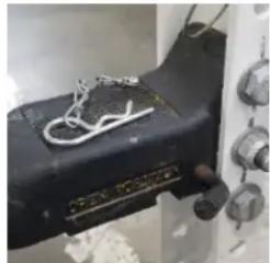
natural_image
Close-up of a black electronic device with wires and knobs, no visible text or symbols-
Using the tongue jack, adjust the height of the tongue for connection to the tow vehicle. Back the tow vehicle under the ball coupler. When the hitch is centered below the ball coupler, stop the vehicle and set the parking brake.
-
Rotate the jack handle counterclockwise until the coupler is in contact with the 2 5/16" tow ball.
-
Move the coupler handle back into place (this locks the tow ball in the coupler) and re-insert safety pin.
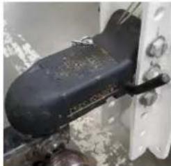
natural_image
Close-up of a black and white object with a handle, possibly a tool or device, against a textured background (no visible text or symbols)-
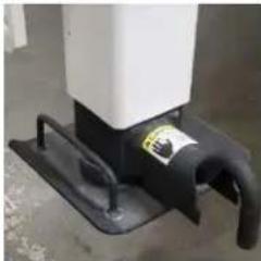
Continue to rotate the jack handle counterclockwise until the jack comes to a stop.
-
Retract the foot extension completely.
natural_image
Close-up of a white industrial device with black components and a curved handle (no visible text or symbols)-
Make the trailer as level as possible. Hitch position adjustment may be required.
-
Attach the safety chains to the tow vehicle. Use the cross-chain method. Chains should cross below the Jack foot.
-
Attach the breakaway switch cable and S hook to the tow vehicle Frame.
The Breakaway Switch cable and S-hook must be attached to the Frame of the tow vehicle independently of all other towing attachments.
It must NOT be attached to the safety chains, hitch, or trailer 7-way connector.
- Attach the 7-way trailer connector and check the taillight and electric trailer brake operation. If your tow vehicle does not have a 7-way connector, it is not appropriately configured to tow the SkyWatch tower. This must be corrected before attempting to tow the tower.
- Remove the wheel chocks.
WARNINGS!
-
TEST TRAILER BRAKES AND MAKE SURE SAFETY CHAINS AND RUNNING LIGHTS ARE PROPERLY CONNECTED TO THE TOWING VEHICLE BEFORE ATTEMPTING TO TOW THE SKYWATCH.
-
OBSERVE ALL POSTED SPEED LIMITS WHILE TOWING. THE MAXIMUM TOWING SPEED OF THE SKYWATCH IS 45 MPH.
-
DO NOT PUT ANY ADDITIONAL EQUIPMENT INSIDE THE OFFICER'S COMPARTMENT OR ON THE TRAILER DECK UNLESS PROPERLY SECURED.
-
DO NOT ALLOW ANYONE TO OCCUPY THE OFFICER'S COMPARTMENT WHILE THE SKYWATCH IS BEING TOWED.
-
DO NOT CARRY ADDITIONAL EQUIPMENT IN THE BED OF THE TOW VEHICLE TO AVOID EXCEEDING VEHICLE WEIGHT LIMITATIONS.
-
THE BREAKAWAY SWITCH CABLE AND S-HOOK MUST BE ATTACHED TO THE FRAME OF THE TOW VEHICLE INDEPENDENTLY OF ALL OTHER ATTACHMENTS. IT CAN NOT BE ATTACHED TO THE SAFETY CHAINS, HITCH OR 7-WAY CONNECTOR.
CAUTION!
CHECK LIGHT HOOK-UP FOR FULL FUNCTION PRIOR TO TRANSPORT.
9.4 SAFELY TOWING THE SKYWATCH
Use this procedure when it is necessary to move the SkyWatch for relocation or storage. This procedure assumes that the officer's compartment has been lowered and the systems have been shut down.
WARNING!
DO NOT ALLOW ANYONE TO RIDE ON THE TRAILER OR IN THE OFFICER'S COMPARTMENT WHILE THE SKYWATCH IS BEING TOWED.
CAUTION!
ALL PAYLOADS MUST BE REMOVED AND PROPERLY STOWED BEFORE TOWING THE PLATFORM.
CAUTION!
USE EXTREME CAUTION WHEN TOWING THE SKYWATCH. DO NOT EXCEED 45 MPH (72.4 KPH) ON PAVED ROADS. OFF-ROAD TOWING SPEED SHOULD NOT EXCEED 15 MPH (24 KPH).
CAUTION!
DO NOT TOW THE SKYWATCH WITH THE CAMEERAS OR WINDSPEED METER MOUNTED. REMOVE THESE PAYLOADS AND STORE THEM IN THE OFFICER'S COMPARTMENT PRIOR TO MOVING THE TRAILER.
- Make sure the SkyWatch is properly attached to the tow vehicle, and that the hitch, safety chains, electrical cable and breakaway switch are all connected properly.
- Make sure the trailer lights and Electric Brakes are functioning properly.
- Make sure the tires on both the SkyWatch and the tow vehicle are properly inflated. Check your tow vehicle's manual for proper inflation pressure.
- Whenever you stop the vehicle for an extended period, check the hitch, chains, electrical connection, and breakaway switch again.
- Always follow trailer speed limitations and posted speed limits.
10.0 SETUP
WARNING! DO NOT ATTEMPT TO ELEVATE YOUR SKYWATCH UNTIL ALL OUTRIGGERS AND ADJUSTABLE STABILIZERS ARE PROPERLY DEPLOYED. FAILURE TO COMPLY MAY RESULT IN PERSONAL INJURY OR DEATH. MAKE SURE THE TRAILER'S TIRES ARE PROPERLY CHOCKED BEFORE ATTEMPTING TO ELEVATE THE OFFICER'S COMPARTMENT.
CAUTION!
MAKE SURE THE SKYWATCH IS DEPLOYED ON FIRM AND LEVEL SURFACES. AVOID SOFT OR UNEVEN SURFACES. FOR MAXIMUM STABILITY, THE SKYWATCH SHOULD BE FULLY ELEVATED OR FULLY LOWERED DURING DEPLOYMENT. WHEN THE SKYWATCH IS DEPLOYED, THE AREA AROUND THE TOWER SHOULD BE ROPED OR CONED-OFF FOR ADDED SAFETY.
10.1 SITE SELECTION
We recommend the following guidelines when considering a deployment:
- Select a site where the terrain is level and firm as possible.
- There should be a clear line-of-sight from the platform to the terrain to be covered by observation or if equipped, cameras, spotlight, and/or radar payloads.
- Do not deploy the SkyWatch in standing water.
- The nearest overhead obstruction (Trees, light poles, overhead wiring) should be approximately 72 feet or 22 meters away from the SkyWatch in all directions.
- Make sure that one wheel is chocked on each side of the Tower.
Note that in softer Ground conditions, it may be necessary to only use one wheel chock per side.
natural_image
Close-up of a car tire mounted on a platform, showing tread pattern and mounting base (no text or symbols visible)- Deploy the outriggers.
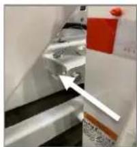
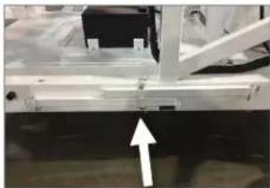
a. Release safety pin from both Rear Outriggers and swing both Rear and then Front Outriggers out to approximately 100 degrees to the trailer.
natural_image
Close-up of a mechanical component with a white arrow pointing to a blue section (no visible text or symbols)b. Pull the center safety pin and swing locking bars toward the outriggers.
natural_image
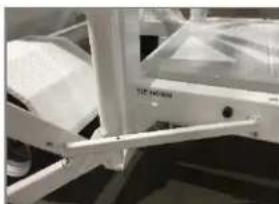
Close-up of a mechanical assembly with a white arrow pointing to a component (no visible text or symbols)c. Secure locking bar to all four outriggers by securing safety pin in hole provided on the outrigger. Note the mounting tab goes inside the notch on the stabilizer bars.
natural_image
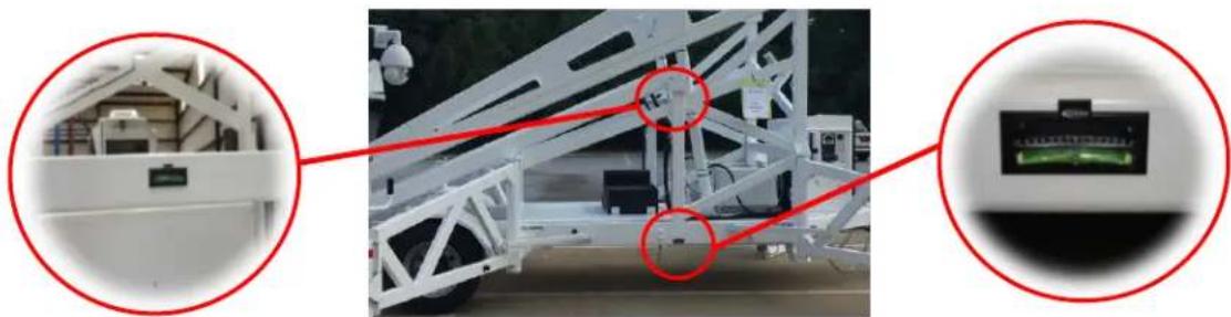
Close-up of a white mechanical device with lever arms and a transparent top (no visible text or symbols)- Locate the four (4) leveling bubbles on the tower.
natural_image
Exterior view of a white industrial crane with red circular annotations highlighting components (no readable text or symbols)The levels used to level tower front-to-back are located at the base of each lower strut support column.
The level used to level tower left-to-right are located on the front of the cross beam directly above the generator. The second left-to-right level is on the rear of the cross beam above the axle in front of the Pillar Block Assembly.
- Using the tongue jack, completely disconnected from the tow vehicle, slowly adjust the height of the front of the trailer to bring the front-to-back leveling bubble into level. Raise the jack by rotating the handle clockwise, lower the jack by rotating the handle counterclockwise.
- Pull the foot release handle and drop one rear jack foot on the lowest off level side of the tower rear axle. Turn the jack handle clockwise to lock the pull handle in place on the lowest side of the trailer and slowly adjust that jack to bring the left-to-right leveling bubbles into level.
- Confirm the tower is completely level, then drop the remaining 3 outrigger jack feet and lock in place by turning the jack handle clockwise until the pull handle locks.
NOTE
While leveling the trailer, initial leveling is performed with only 2 jacks: the tongue jack and the off side rear outrigger jack. Do not deploy any other jacks or lock them prior to initial leveling.
- Starting with the already deployed rear outrigger jack only, raise this jack one inch. You can easily, ensure one inch measuring the distance between the top of the tire and the fender lip, and increase that distance by one inch, (approximately the width of an average finger). Generally, this is approximately 4 complete clockwise handle rotations.
- Go to the opposite rear outrigger jack and raise this one inch as well using the same measuring method used to raise the first rear Jack one inch. Left-to-right leveling should still be maintained.
NOTE
Do not adjust more than one rear outrigger jack at a time or both jacks will interfere with correct height adjustments.
-
Lower and lock the jack feet on both front outrigger jacks. Slowly adjust the left and right jacks until the one inch measurement appears under the hitch jack foot, maintaining left-to-right leveling. When complete, front-to-back leveling, and side-to-side leveling should still be level.
-
Minor adjustments to front-to-back leveling can be performed with the left and right front outrigger jacks together.
Do not use hitch jack for leveling at this point. The hitch jack foot should still be off the ground one inch.
Minor adjustments to left to right leveling can be made with the front and rear jacks on the same side.
- When the Tower is level, and confirmed to be raised one inch, the tower has reached maximum stability. At this point, lower the hitch jack foot until it contacts the ground and has weight on it, but does NOT raise the tower. The jack is raised just until it stops rattling and moving when tapped with your foot.
10.3 MOUNTING THE ANEMOMETER
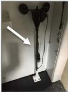
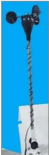
The anemometer (wind cups) provides an indication of the wind speed around the SkyWatch.
- Open the officer's cab and retrieve the anemometer from its storage mount.
natural_image
Interior view of a room with a black device and wires, no visible text or symbols- Insert the anemometer pole into the mount on the top of the officer's compartment. Tighten the knob to secure the anemometer in the mount.
natural_image
Close-up of a black metal stand with coiled wires against a blue background (no text or symbols visible)- Insert the anemometer cable connector into its receptacle under the cab mount and twist the outer ring until the connector is seated. Before inserting, inspect the connector to ensure the connector is keyed correctly before proper positioning into the receptacle.
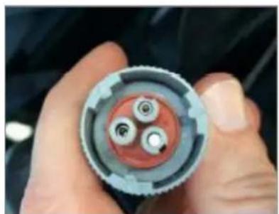
natural_image
Close-up of hands holding a mechanical component with three circular features (no visible text or symbols)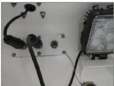
natural_image
Close-up of electrical connectors and a digital display unit (no visible text or symbols)10.4 MOUNTING THE PAYLOADS
While the SkyWatch can support a variety of optional payloads, all the payloads have a common mount that is installed at the FLIR factory. The common payloads are installed using the following procedures. Should you acquire payloads from a supplier other than FLIR, contact your FLIR service representative for a mount power connector that will interface with the SkyWatch system.
- All FLIR-supplied payloads (fixed cameras, pan and tilt cameras, thermal imagers, radar, etc.) are mounted in common mounting rails attached to the SkyWatch system. FLIR mounts are designed to slide into these mounting rails and lock into place.
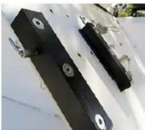
natural_image
Two black rectangular metal components with circular holes, placed on a white surface (no text or symbols visible)- To mount a payload, pull the mount locking pin out, slide the payload mount into the SkyWatch mount receiver, and allow the locking pin to snap back into place.
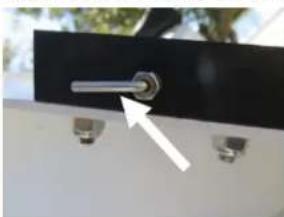
natural_image
Close-up of a metallic lever mounted on a black panel with two small screws attached (no text or symbols visible)- Connect the payload power and/or data line into the appropriate SkyWatch connector. See the payload's manual for more information.
CAUTION!
DO NOT TOW THE SKYWATCH WITH THE PAYLOADS OR ANEMOMETER MOUNTED. REMOVE ALL THE PAYLOADS AND STORE THEM IN THE OFFICER'S COMPARTMENT PRIOR TO MOVING THE TRAILER.
11.0 OPERATION
This section covers various operational aspects of the SkyWatch during normal operations while at the deployment location. Remember that performing this process may require the completion of several procedures. Be sure to review all the steps necessary to complete a procedure before performing it.
11.1 WALK-AROUND AND POWER-UP PREPARATIONS
Prior to each time the platform is powered-up, perform a walk-around inspection to ensure safe operation. This procedure verifies that the platform is safe and ready for operation. Be sure to log and report any safety or operational discrepancies, and do not proceed until any safety concerns have been addressed.
- Make sure that the SkyWatch is positioned so that there are no overhead obstructions when deploying the officer's compartment. Reposition the platform if necessary.
WARNING!
DO NOT DEPLOY THIS PLATFORM UNDER POWER OR COMMUNICATIONS LINES OR UNDER OVERHEAD OBSTRUCTIONS. MAKE SURE THE PLATFORM IS NOT SET UP WITHIN 72 FEET (APPROXIMATELY 22 METERS) OF ANY POWER OR COMMUNICATION LINES.
- Visually verify that the one wheel on each side of the trailer is chocked.
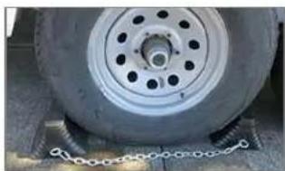
natural_image
Close-up of a car tire mounted on a lift with chains attached (no visible text or symbols)- Visually verify that all four jack legs are in contact with the ground and the jack leg locking handles are engaged, as shown.
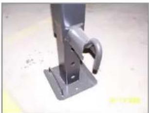
natural_image
Close-up of a metal bracket with a curved handle and mounting base (no text or symbols visible)-
Visually verify that the platform is level using the 4 levels on the trailer. (see section 10.2)
-
Verify that the outriggers are deployed and locked.
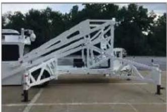
natural_image
Exterior view of a white metal truss structure on a paved lot, with a person standing nearby (no visible text or symbols)- Walk around the platform and make sure that there are no visible oil or fuel leaks.
11.2 POWER-UP USING SHORE POWER
- Shore power requires a NEMA SS2-50R Connector, as shown. A weather boot is recommended.
We do not recommend Dog bone, Pigtail or Low current adaptors be used in any situation as they are prone to overheating and failure.
Shore power supply is 230VAC 50Amp.
Maximum supply cord length is 100Ft, maintaining a 50 amp output.
Please Call Customer Service for Alternate dual 125VAC 50amp connection.
Electrical connections to the SkyWatch Tower Should be made by a licensed electrician.
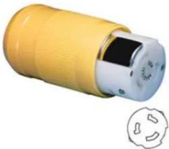
natural_image
Yellow and white electrical connector with a circular socket, shown with a separate symbol below (no text or labels visible)-
Connect the shore power cable to the power source.
-
Connect the SS2-50R female connector to the shore power SS2-50P Male on the right side (curb side) of the electrical compartment.
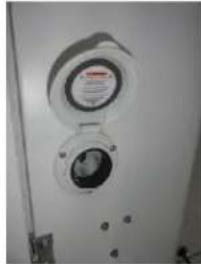
natural_image
Close-up of a white wall-mounted air conditioner unit with two circular gauges and a central display (no visible text or symbols)- On the panel inside the electrical compartment, locate the circuit power selector panel. Make sure Generator circuit breaker is off. Slide circuit bar up and then turn on breaker for the Shore Power.
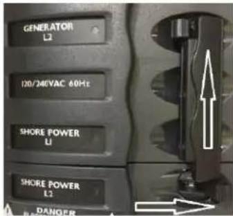
-
When power is applied from the external shore power source, the Shore power L1 and L2 Breakers will have a red indicator that they are powered on. The SkyWatch will be operable on shore power.
-
Close and lock the electrical compartment to prevent unauthorized access when an observer is in the raised officer's compartment.
11.3 POWER-UP USING THE GENERATOR
- Confirm there is fuel in the fuel tank.
The picture shows the fuel tank access panel for the diesel fuel tank. If using the gasoline generator, the fuel tank will be mounted on the trailer deck.
natural_image
Open laboratory medical device with clamps and a black circular component (no visible text or labels)- On the panel inside the electrical compartment, locate the circuit power selector panel. Make sure Shore Power circuit breaker is off. Slide circuit bar down and then turn on breaker for the generator.
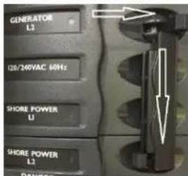
- To start either the diesel or the gasoline generator, locate the generator control toggle switch on the generator operator panel. Press and hold the Start/Preheat switch until the generator starts.
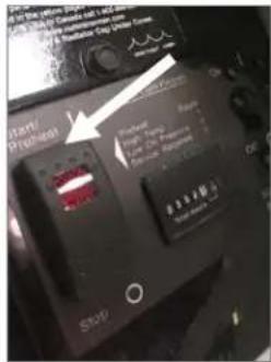
Diesel Generator Operators Panel
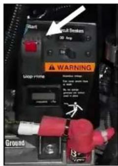
Gasoline Generator Operators Panel
See the generator manual for more information on starting and troubleshooting if needed.
- Always close and lock the electrical compartment to prevent unauthorized access when the observer is in the raised officer's compartment.
11.4 PREPARING THE OFFICER'S COMPARTMENT
- On the Pillar Block Assembly used to secure the cab during transit, release the latches on each side and rotate them so that they rest outside of where the arms will move when raising or lowering the Tower.
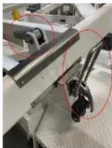
natural_image
Close-up of a mechanical assembly with red circles highlighting specific components (no visible text or symbols)- When the cab is raised and lowered, it will return to the 12 inch transport height or "Stow" configuration, shown here.
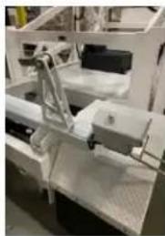
natural_image
Industrial machine component with white frame and metal clamping mechanism (no visible text or symbols)- If in the "Ground" configuration, shown here, change to the "Stow" configuration by rotating and pinning the pillar on the Pillar Block Assembly.
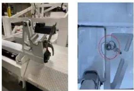
natural_image
Two-panel image: left shows a mechanical device on a workbench, right shows a close-up of a mechanical component with a red circle highlighting a detail (no visible text or symbols)11.5 RAISING THE OFFICER'S COMPARTMENT
The officer's compartment can be raised from either the momentary switch in the officer's compartment, or from the up/down momentary switch in the electrical compartment. Be sure to follow operational limitations to ensure safe operation.
WARNING!
DO NOT RAISE THE OFFICER'S COMPARTMENT WITHOUT THE OUTRIGGERS DEPLOYED AND LOCKED.
WARNING!
DO NOT DEPLOY THE OFFICER'S COMPARTMENT IN SUSTAINED WINDS EXCEEDING 60 MPH (96.5 KPH).
CAUTION!
PILLAR BLOCK LATCHES MUST BE DISENGAGED PRIOR TO RAISING OR LOWERING OFFICER'S COMPARTMENT TO AVOID DAMAGE TO SYSTEM.
CAUTION!
THE OFFICER'S COMPARTMENT HAS A MAXIMUM RECOMMENDED WEIGHT LIMIT OF 3500 LBS. (1587 KG) OR 3100 LBS. (1406 KG) ON 2-MAN UNITS (THIS FIGURE DOES NOT INCLUDES ALL OPTIONAL PAYLOAD.
CAUTION!
DO NOT OPERATE THE HEATER WHILE RAISING THE OFFICER'S COMPARTMENT.
NOTE
The air conditioner will turn off when the officer's compartment is in motion and will remain off for several minutes. The air conditioner's fan will remain operating.
- Verify that the wheels are chocked, outriggers deployed, the pillar block latches are disengaged, and the trailer is level.
- Verify power is being supplied to the officer's compartment by either shore power or generator.
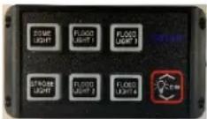
If operating on generator power, verify there is sufficient fuel to run the generator for the duration of the mission.
- Verify wind speed display in the officer's compartment reads less than 60 mph.
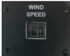
- Make sure that the door to the officer's compartment is closed, latched, and secured with the safety cable.
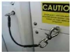
- Locate momentary switch on the main console. Firmly hold the switch until it is fully deployed. It will take approximately 90 seconds for the officer's compartment to reach its fully deployed height. The compartment will stop when it has reached its full deployment height. When the compartment stops moving, release the button.
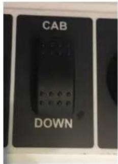
CAUTION! NEVER DEPLOY THE SKYWATCH AT LESS THAN ITS FULL HEIGHT. THE TOWER MUST BE FULLY RAISED OR FULLY LOWERED.
-
Verify that the wheels are chocked, outriggers deployed, the pillar block latches are disengaged, and the trailer is level.
-
Go to the officer's compartment and verify power is being supplied to the officer's compartment by either shore power or generator.
If operating on generator power, verify there is sufficient fuel to run the generator for the duration of the mission.
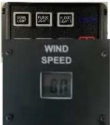
-
Verify wind speed display in the officer's compartment reads less than 60 mph.
-
Exit the officer's compartment, making sure that the door to the officer's compartment is closed and latched.
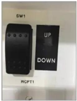
- Locate the up/down momentary switch in the electrical compartment.
Press and hold the UP button until the officer's compartment is fully deployed. It will take approximately 90 seconds for the officer's compartment to reach its full deployed height. The compartment will stop when it has reached its full height. When the compartment stops moving, release the button.
CAUTION!
DO NOT DEPLOY THE SKYWATCH AT LESS THAN ITS FULL HEIGHT.
11.6 LOWERING THE OFFICER'S COMPARTMENT
The officer's compartment can be lowered from either the momentary switch in the officer's compartment, or from the up/down momentary switch in the electrical compartment. The officer's compartment will naturally rest approximately 12 inches above the ground on the Pillar Block Assembly. If bringing the officer's compartment completely to the ground is required, this can be achieved by removing the Clevis Pins and rotating the Pillar Blocks down and out of the way, resting on the Fenders. Be sure to follow operational limitations to ensure safe operation.
CAUTION!
PILLAR BLOCK ASSEMBLY LATCHES MUST BE DISENGAGED PRIOR TO RAISING OR LOWEING OFFICER'S COMPARTMENT TO AVOID DAMAGE TO SYSTEM.
CAUTION!
BOTH PILLAR BLOCKS MUST BE IN THE SAME LOCATION (UP AND PINNED OR DOWN, RESTING ON THE FENDERS) PRIOR TO OPERATION.
- Locate the momentary switch on the main console.
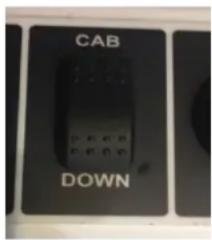
- Firmly hold the momentary switch until the compartment is fully in the down position. It will take approximately 90 seconds for the officer's compartment to descend from its fully deployed height. When the compartment has stopped moving, release the button.
- Locate the up/down momentary switch in the electrical compartment.
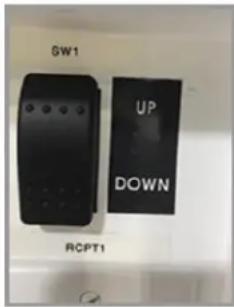
- Press and hold the DOWN button until the officer's compartment is resting on the ground. It will take approximately 90 seconds for the officer's compartment to reach the ground from its fully deployed height. When the compartment stops moving, release the button.
11.7 GENERATOR OPERATION
STARTING THE GENERATOR FROM THE OFFICER'S COMPARTMENT
This procedure assumes that the SkyWatch input power is set to ONAN and that the system was previously being powered by the generator.
- Confirm there is fuel in the fuel tank
- Push and hold the control switch at the START position until the generator starts. The status indicator light on the switch will flash during preheat and cranking. The light will stay on solid when the starter disconnects, indicating that the generator is running. Depending on how cold it is, preheat can take up to 15 seconds, extending the time that the light blinks.
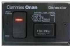
See the generator manual for more information on starting and troubleshooting if needed.
STOPPING THE GENERATOR FROM THE OFFICER'S COMPARTMENT
- Locate the generator control toggle on the main console of the officer's compartment.
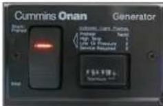
- Press and hold the STOP portion of the toggle until the generator stops.
See the generator manual for more information on stopping and troubleshooting if needed.
STARTING THE GENERATOR FROM THE GENERATOR OPERATOR'S PANEL
- Visually confirm there is fuel in the fuel tank.
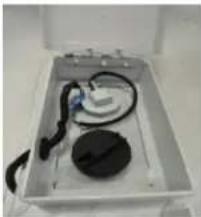
natural_image
White laboratory equipment with black components and tubing, no visible text or symbols- Visually confirm the generator breaker is on in the breaker panel selector panel.
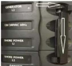
- Push and hold the control switch at the START position until the generator starts.
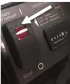
- The status indicator light on the switch will flash during preheat and cranking. The light will stay on solid when the starter disconnects, indicating that the generator is running. Depending on how cold it is, preheat can take up to 15 seconds, extending the time that the light blinks.
See the generator manual for more information on starting and troubleshooting if needed.
STOPPING THE GENERATOR FROM THE GENERATOR OPERATOR'S PANEL
-
Locate the generator control toggle switch on the generator operator panel.
-
Press and hold the STOP / PRIME portion of the switch until the generator stops (diesel generator panel shown).
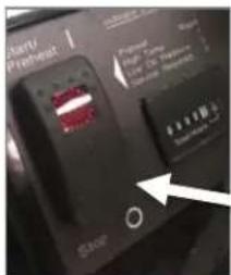
See the generator manual for more information on stopping and troubleshooting if needed.
11.8 SYSTEM SHUTDOWN
This procedure is used to shut the SkyWatch down, with no power going to the system, in preparation for transport or redeployment of the trailer.
- Turn power off to all the following components in the officer's compartment:
a. Payloads
b. Interior/Exterior, lights/floods, and spotlights
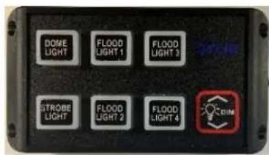
c. PA system
d. Heater or air conditioner (For operator comfort the air conditioner and heater can be operated during compartment descent.)
- Locate the momentary switch on the main console.
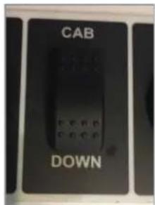
-
Firmly hold the momentary switch until the officer's compartment is resting on the ground or Pillar Block Assembly It will take approximately 90 seconds for the officer's compartment to descent from its fully deployed height. The compartment will stop when it has reached either the ground or the Pillar Block Assembly Release the switch.
-
If not completed in step 1, turn off power to the following components:
a. Heater
b. Air conditioner
-
Remove the door safety cable, open the door, and exit the officer's compartment. Reclose and lock the compartment door. If the officer's compartment is already secured in the Pillar Block Assembly for transport, skip to STEP 8.
-
If the officer's compartment has descended to the ground, on the panel in the electrical compartment, locate the up/down momentary switch. Press and hold the UP button until the officer's compartment is approximately five feet above the ground.
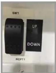
-
From up/down momentary switch, press and hold the DOWN button until the officer's compartment is resting on the Pillar Block Assembly.
-
If the SkyWatch is operating using the on-board generator, press and hold the STOP portion of the switch until the generator stops.
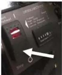
- If the SkyWatch is running on shore power:
a. Inside the electrical box, make sure that the breakers for both generator and shore power are turned off. This shuts down the SkyWatch.
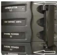
b. Open CB 4 inside the electrical compartment to isolate the generator start battery from the generator.
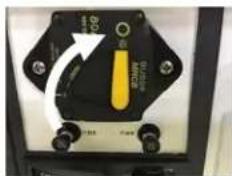
CAUTION!
PILLAR BLOCK ASSEMBLY LATCHES MUST BE CLEAR FROM THE PATH OF THE LIFTING ARMS TO AVOID DAMAGE TO THE UNIT.
CAUTION!
UNIT MUST BE LEVEL AND BOTH PILLAR BLOCKS MUST BE IN THE SAME LOCATIONS TO PREVENT DAMAGE THE TOWER.
11.9 PREPARING THE SKYWATCH FOR TOWING
This procedure is used to prepare the SkyWatch for towing. Be sure to complete the previous procedure to make sure that the SkyWatch is shut down properly.
- If the SkyWatch was previously running on shore power, disconnect the external power supply cable from the shore power pigtail.
- Carefully climb up onto the back of the trailer in front of the officer's compartment. Disconnect the anemometer's connector from its plug on the officer's compartment. Replace the plug cover.
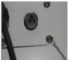
natural_image
Close-up of electrical connectors and wiring (no visible text or symbols)- Remove the anemometer from its mount on the roof of the officer's compartment. Be sure to tighten the locking knob after the anemometer has been removed to prevent it from being lost during transport.
- Stow the anemometer in its storage mount in the officer's compartment on the right just inside the door.
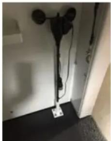
natural_image
Interior view of a room with black cables and a small electrical outlet (no visible text or symbols)- Remove the payloads from the officer's compartment. Stow the payloads in their approved enclosures and store them in the officer's compartment.
See the payload manuals for detailed instructions.
- Raise the tower and the Pillar Blocks into transport position and replace the clevis pins, if not already in the transport position.
Lower the tower onto the raised Pillar Blocks. Flip all the Pillar Block latch hooks down, connect through the U-bolt catch, and firmly press down on the handle to engage the
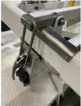
natural_image
Close-up of a mechanical device with metal components and a black tool, no visible text or symbolstransport latches.
- Loosen outrigger jacks.
a. Rotate handles counterclockwise.
b. Pull the extension handle.
c. Lift the jack foot to the bottom of the jack and release the extension handle to stow the extension in the jack shaft.
d. Ensure the extension handle is locked in and the jack base is secured.
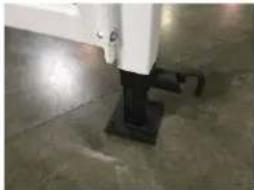
natural_image
Close-up of a concrete floor with a white structural component and black base (no visible text or symbols)- Remove the safety pins from pivot bar on all the outriggers and swing the pivot bar back toward the trailer. Make sure to reinstall safety pin back in the same hole on the outrigger once pivot bar is free. Secure the pivot bar with provided safety pin.
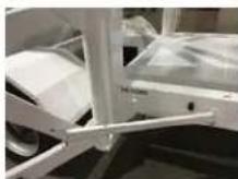
- Perform steps 6 and 7 on all remaining outriggers. Swing front outriggers back to the trailer, then swing the rear outriggers over the front outriggers.
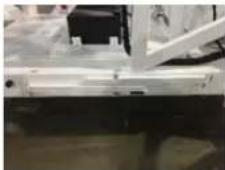
- Attach the outrigger safety pin on both sides of the trailer.
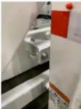
- Remove the wheel chocks from both sides of the trailer. Stow the wheel chocks in the officer's compartment.
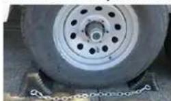
-
In the officer's compartment, secure all payloads, wheel chocks, and other stored equipment using the tie down points provided. Make sure the chair is not capable of rolling around inside the compartment. Close and lock the officer's compartment door.
-
Close and lock the electrical compartment door.
11.10 STORING THE SKYWATCH
This procedure should be used whenever a platform is removed from service and placed into storage for an extended period (more than 90 days).
- Inside the electrical box, make sure that the breakers for both generator and shore power are turned off.
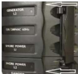
- On the generator operator's panel, move the circuit breaker switch to the OPEN (OFF) position.
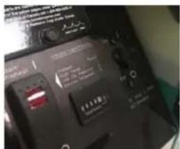
- In the electrical compartment locate the cab power, climate control and spare breakers. Set all to the OPEN (OFF) position.
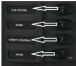
- Open the electrical compartment and locate the 80 A generator starter battery circuit breaker and set it to the OPEN (OFF) position as shown:
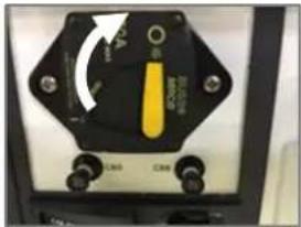
natural_image
Close-up of a black electrical switch with yellow and white adjustment knob (no visible text or symbols)-
Change the generator oil using the recommended engine oil. Note the type of oil and amount used and update the platform's maintenance log.
-
Plug the exhaust pipe to keep out dirt, moisture, insects, etc.
-
Make certain that all the platform's covers, lids, and accesses are closed and locked.
If the platform is to be stored for an extended period, store indoors or under cover. Attach float charger to the generator starter battery to maintain its charge.
12.0 TROUBLESHOOTING
| PROBLEM | PROBABLE CAUSE | SOLUTION |
| Officer's compartment fails to ascend | Officer's compartment door is not closed | Close and secure the door |
| Moaning and vibrations (usually during ascent) | Unit has not been properly lubricated.Cylinder seal has dried out | Refer to Section 13.2: Scheduled Maintenance.Apply gun oil (Rem Oil) where rod moves out of cylinder. |
| Electrical systems not operating | Power input selector switch is set to OFF.Circuit has been overloaded.Generator is not running.Shore power cord is not plugged into an outlet. | Set the power input selector switch to either SHORE or ONAN as required by the input power sourceReset generator circuit breaker. Reset circuit breakers in technical compartment.Restart generator.Plug cord into an outlet. Verify outlet circuit not overloaded. |
| Difficulty in towing | Trailer not properly connected to tow vehicle.Excess weight in Officer's CompartmentTires not properly inflated | Refer to Section 9.3: Coupling SkyWatch to Tow Vehicle.Verify that extra items are not stowed in Officer's Compartment.Verify tires are properly inflated, |
13.0 MAINTENANCE
13.1 GENERAL MAINTENANCE
As a matter of your daily routine, you should visually inspect your SkyWatch for any obvious signs of mechanical damage, leaking fluids, electrical system problems or other maintenance issues. While your SkyWatch has been designed to require minimal routine maintenance, careful attention to the condition of your system can help prevent minor problems from becoming significant maintenance items.
LUBRICATION SYSTEM
The SkyWatch is equipped with 5 grease fittings for lubricating each pivoting joint. These grease fittings are located as follow:
| Location | Total |
| 1 on each Tongue Jack | 1 |
| 1 on each Outrigger Jack Strut | 4 |
These joints are lubricated prior to shipment, but require regular lubrication as outlined in the scheduled maintenance section of this chapter.
BATTERY CARE
The start battery is used to crank the generator. This battery is charged by the generator and by the installed solar panel only. It is important to keep your solar panel clean and free from dust to allow optimal battery charging.
Status lights on the solar charge controller indicate if the solar panel is charging the battery. If this light is not illuminated, check the condition of, and connections to, the solar panel. If the SkyWatch is stored in a location that has insufficient sunlight (e.g. indoors) an automatic float charger should be used to maintain battery charge.
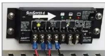
Figure 29: Solar Charge Controller
HYDRAULIC SYSTEM
The fill cap is located on the top of the pump reservoir. Only add fluid if the SkyWatch does not elevate to full height. Contact your FLIR Customer Support Center to determine if this is the cause.
CAUTION!
- USE ONLY DEXRON TRANSMISSION FLUID FOR THE HYDRAULIC SYSTEM. THE RESERVOIR SHOULD BE FILLED TO WITHIN 14 " OF THE TOP OF THE SIGHT GLASS.
- ONLY MEASURE THE RESERVOIR WHEN THE OFFICER'S COMPARTMENT IS ON THE GROUND. MEASURING OR FILLING THE RESERVOIR WHEN THE OFFICER'S COMPARTMENT IS ON THE STRAPPING BRACKET WILL OVERFILL THE RESERVOIR.
FLOW CONTROL VALVE
CAUTION!
DO NOT ADJUST THIS VALVE. CONTACT YOUR FLIR SERVICE REPRESENTATIVE.
The flow control valve is set at the factory so that the descent of a fully elevated officer's compartment to the ground should take approximately 90 seconds. You may need a FLIR technician to adjust this valve due to any of the following conditions:
- Temperature
- Altitude
• Hydraulic fluid in system - Excessive humidity
• Normal mechanical wear
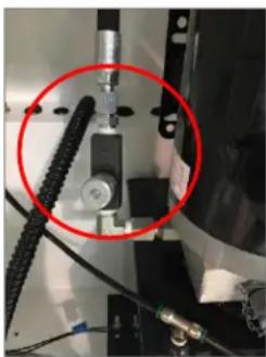
natural_image
Close-up of mechanical components with a red circle highlighting a specific part (no visible text or symbols)Figure 30: Flow Control Valve
NOTE
It is NOT recommended to use descent rates faster than 90 seconds.
PUMP FLOW RATE ADJUSTMENT
CAUTION!
DO NOT ATTEMPT TO ADJUST THIS FITTING. CONTACT YOUR FLIR SERVICE REPRESENTATIVE.
These adjustments (located on each pump) are set at the factory to provide optimal integration with the rest of the components in the hydraulic system. Incorrect calibration of this component can cause:
Hydraulic motor failure due to excessive back pressure from the pump
Cylinder failure due to excessive hydraulic fluid pressure on the cylinder seals
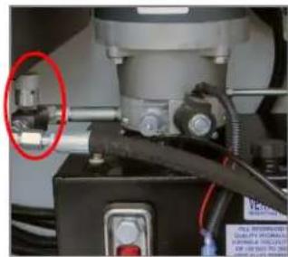
natural_image
Close-up of mechanical components with a red circle highlighting a component (no visible text or symbols)Figure 31: Pump Flow Rate Adjustment
13.2 GENERATOR MAINTENANCE
Refer to the generator operator's manual for details about maintenance on your on-board generator. Your SkyWatch is equipped with an oil drain hose and valve for quick and convenient oil changes (not applicable on gasoline generators).
CAUTION!
MAKE SURE THAT THE OIL DRAIN VALVE IS SECURELY CLOSED BEFORE REFILLING WITH OIL.
13.3 SCHEDULED MAINTENANCE
Establish and adhere to a definite schedule of maintenance and service. If the Tower is subjected to extreme operating conditions, consult a FLIR customer support specialist, to determine the appropriate maintenance schedule.
Keep an accurate log of all maintenance and service, for warranty support.
| Scheduled Hydraulic System Maintenance | Daily | Weekly | Monthly | 3x per Year | Annually |
| Weep Lines | |||||
| Make sure they are strapped to Cylinders with wire ties | ● | ||||
| Make sure they are not cracked or damaged | ● | ||||
| Make sure they are connected to fittings at cylinder and pump | ● | ||||
| High Pressure Lines | |||||
| Check Fittings at Cylinders and Pump for leaks | ● | ||||
| Inspect Hose condition and check for leak | ● | ||||
| Pump and Motor | |||||
| Check hydraulic fluid | ● | ||||
| Check pumps for leaks and loose connections | ● | ||||
| Visual inspection for loose wiring | ● | ||||
| Inspect fill cap condition | ● | ||||
| Perform e-down function test | ● | ||||
| Cylinders | |||||
| Clean piston shaft (in up position) | ● | ||||
| Check external seals for leaks (by raising and lowering tower twice) | ● | ||||
Perform all maintenance at the operational hours as indicated. Use this schedule to determine the maintenance required.
Refer to the generator manual for information on procedures, warnings, and troubleshooting.
SCHEDULED HYDRAULIC SYSTEMS MAINTENANCE
^1 Check for any leaks of hydraulic fluid and make notes of any maintenance concerns
SCHEDULED GENERATOR MAINTENANCE
| Scheduled Generator Maintenance | Daily | Weekly | Monthly | 3x per Year | Annually |
| Engine | |||||
| Check coolant | ● | ||||
| Check coolant anti-freeze protection every 500 hours | ● | ||||
| Flush coolant / replace pressure cap every 1000 hours | ● | ||||
| Replace Spark Plug every 550hrs (Gasoline Models ONLY) | ● | ||||
| Run test 15 minutes (check oil before starting generator) | ● | ||||
| Change Engine Oil every 350hrs, replace Oil Filter | ● | ||||
| Replace Air Filter every 350hrs | ● | ||||
| Replace fuel filter every 1100 hours or as needed | ● | ||||
| Test breaker on generator | ● | ||||
| Check exhaust - is tail pipe secure | ● | ||||
| Clean spark arrestor every 150 hours (gasoline engine only) | ● | ||||
| Replace engine V-belt every 1000 hrs^1 (Must be performed by an Onan authorized mechanic) | ● | ||||
| Clean crankcase breather every 1000 hrs^1 (Must be performed by an Onan authorized mechanic) | ● | ||||
| Replace coolant hoses and thermostat every 1000 hrs^1 (Must be performed by an Onan authorized mechanic) | ● | ||||
| Other Engine Components/Functions | |||||
| Test remote start from officer's compartment | ● | ||||
| Check for fuel tank leaks | ● | ||||
| Verify fuel lines secured | ● | ||||
| Examine Fuel Cap | ● | ||||
^1 The maintenance schedule for performance-based components (i.e. Scheduled engine maintenance) includes two numbers. One is based on the number of hours the component has been used, and the second is calendar-based. Maintenance intervals for these compartments should be whichever of the two numbers is lower.
^2 Perform at least once every two years
^3 As part of engine break-in, change the engine oil after the first 50 hours of operation.
^4 Perform more often when operating in dusty conditions
^5 Perform more often when operating in hot weather
^6 Perform at least once a year
SCHEDULED ELECTRICAL SYSTEM MAINTENANCE
| Scheduled Electrical System Maintenance | Daily | Weekly | Monthly | 3x per Year | Annually |
| Solar Charging System | |||||
| Test generator start battery (check voltage) | ● | ||||
| Clean solar panel and check for damage | ● | ||||
| Test solar panel charger | ● | ||||
| Are wires running to panel and start battery secure? | ● | ||||
| 12 Volt System – Officer's compartment | |||||
| Test interior light | ● | ||||
| Test fuel gauge | ● | ||||
| Test door relay switch / safety switch | ● | ||||
| Test Up/Down Switch | ● | ||||
| Test 12 Volt outlet | ● | ||||
| Test descent alarm | ● | ||||
| Test strobe light | ● | ||||
| Verify Digital Wind Speed Meter is working properly | ● | ||||
| 12 Volt System – Electrical Compartment | |||||
| Test Up/Down Switch | ● | ||||
120 Volt AC System from Shore Power or Generator – Officer's Compartment
| Test GFI Outlet | ● | ||||
| Perform air conditioner function test | ● | ||||
| Perform heater function test | ● | ||||
| Test camera | ● | ||||
| Test DVR | ● | ||||
| Test monitor | ● | ||||
| Test pan / tilt for camera | ● | ||||
| Test public address system | ● | ||||
| Test spotlights | ● | ||||
| Test floodlights | ● | ||||
| Test fuel gauge light | ● |
120 Volt AC System from Shore Power or Generator – Electrical Compartment
| Test GFI outlet | ● | ||||
| Test Up/Down momentary switch | ● |
SCHEDULED TRAILER MAINTENANCE
| Scheduled Trailer Maintenance | Daily | Weekly | Monthly | 3x per Year | Annually |
| Grease Fittings | |||||
| One points at each outrigger jack (4) | ● | ||||
| One point at front tongue jack | ● | ||||
| Outriggers | |||||
| Check outrigger pins to ensure they are secure and in good working order | ● | ||||
| Inspect outrigger restraining latches | ● | ||||
| Inspect outrigger jacks and bolts connecting them to the outrigger | ● | ||||
| Check outrigger reflective tape | ● | ||||
| Tongue | |||||
| Check Split-ball coupler | ● | ||||
| Check safety chains | ● | ||||
| Check tongue jack | ● | ||||
| Check breakaway brake switch, cable, and 'S' hook | ● | ||||
OTHER SCHEDULED MAINTENANCE
| Other Scheduled Maintenance | Daily | Weekly | Monthly | 3x per Year | Annually |
| Hardware | |||||
| Check exterior door handles on officer's compartment for proper function | ● | ||||
| Check interior door handles on officer's compartment for proper function | ● | ||||
| Check Door latches to be in good order | ● | ||||
| Is generator compartment door handle working correctly | ● | ||||
| Paint | |||||
| Check under-coating under officer's compartment | ● | ||||
| Miscellaneous Inspections | |||||
| Check the condition of the bumpers on bottom of officer's compartment. | ● | ||||
| Check air pressure in tires | ● | ||||
| Inspect wheel hubs | ● | ||||
| Check bubble levels | ● | ||||
| Check warning labels for legibility | ● | ||||
| Inspect door safety cable | ● | ||||
| Inspect windows (cracks, tint, locks) | ● | ||||
| Inspect fire extinguisher | ● | ||||
| Is Officer's Compartment Level | ● | ||||
13.4 OBTAINING SUPPORT OR PARTS
When your SkyWatch Tower requires service, contact FLIR Detection, Inc. Customer Support Center for assistance. Factory trained representatives are prepared to meet your support needs.
For customer support or SkyWatch parts, please call (410) 540-8660 option 2 or visit our website at http://www.flir.com/skywatch.
When contacting customer support, please provide the complete serial number listed on the data plate that is located on the tongue of the trailer.
APPENDIX A - CIRCUIT BREAKER TABLE
| Circuit Breaker | Size | Purpose | Location |
| CB 1 | 30 A | 120 VAC Input Line 1 | Electrical compartment – wiring bus |
| CB 2 | 30 A | 120 VAC Input Line 3 | Electrical compartment – wiring bus |
| CB 3 | 30 A | 12 VDC Input | Electrical compartment – wiring bus |
| CB 4 | 80 A | Generator Start Battery | Electrical compartment – right side |
| CB 5 | 7.5 A | Solar Charge Controller | Electrical compartment – panel |
| CB 6 | 7.5 A | Breakaway Switch | Electrical compartment – panel |
| CB 7 | Not Used | ||
| CB 8 | Not Used | ||
| CB 9 | Not Used | ||
| CB 10 | 20 A | 12 VDC Power | Officers Compartment DC Breaker Panel |
| CB 11 | 15 A | 12 VDC Outlet | |
| CB 12 | 2.5 A | Air Conditioner DC Power | |
| CB 13 | 2.5 A | Cab Up/Down Switch & Fuel Gauge | |
| CB 14 | 2.5 A | Under Cab Camera | |
| CB 15 | 2.5 A | Door Alarm | |
| CB 16 | 7.5 A | Down Relay | |
| CB 17 | 20 A | PA System (if equipped) |
| CB 18 | 2.5 A | Network Switch Power (if equipped) |
| CB 19 | 5 A or 10 A | Front PT Camera Power (if equipped) |
| CB 20 | 5 A or 10 A | Rear PT Camera Power (if equipped) |
| CB 21 | 10 A | Front Go-Light (if equipped) |
| CB 22 | 10 A | Rear Go-Light (if equipped) |
- User Guide
- SkyWatch.Support@flir.com
- Proprietary Information
- Patents
- CONTENTS
- SAFETY 1
- SKYWATCH OVERVIEW....9
- OFFICER'S COMPARTMENT 16
- ELECTRICAL COMPARTMENT 19
- ELECTRICAL SYSTEM....22
- HYDRAULIC SYSTEM 25
- POWER GENERATION 28
- CONTROLS AND INDICATIONS....33
- TOWING THE SKYWATCH 41
- SAFETY
- SAFETY NOTICE CONVENTIONS
- CAUTION!
- NOTE
- SAFETY NOTICES
- WARNING!
- OPERATIONAL SAFETY
- MECHANICAL SAFETY
- STABILITY
- MOVING PARTS
- GENERATOR SAFETY
- EXHAUST FUMES
- ELECTRICAL SAFETY
- TOWING SAFETY
- GENERAL SAFETY
- GLOSSARY
- A
- AC
- °C
- CB
- DC
- °F
- GFCI
- G/hr
- Hz
- L/hr
- V
- VAC
- VDC
- W
- REFERENCED MANUALS
- SKYWATCH OVERVIEW
- CONFIGURATION
- PLATFORM COMPONENTS
- COMPONENT DESCRIPTIONS
- OFFICER'S COMPARTMENT
- WIDE AREA FLOOD LIGHTS
- AIR CONDITIONER
- HYDRAULIC LIFT ARMS
- FUEL TANK
- GENERATOR
- ELECTRICAL COMPARTMENT
- HYDRAULIC CYLINDERS
- SOLAR PANEL
- SKYWATCH SPECIFICATIONS BY MODEL
- PAYLOADS AND OPTIONAL EQUIPMENT
- FLIR® RANGER® MS-UC DEFENDIR PTZ CAMERA
- FLIR® PT- SERIES PTZ CAMERAS
- FLIR® DAY/NIGHT PTZ CAMERA
- ADDITIONAL FIXED CAMERAS
- OPTIONAL EQUIPMENT AND SERVICES
- PUBLIC ADDRESS SYSTEM
- WIRELESS CONNECTIVITY
- ROOF-MOUNTED SEARCH LIGHTS
- SERVICE PLANS
- OFFICER'S COMPARTMENT
- COMPONENT DESCRIPTIONS
- MAIN CONSOLE
- LIGHTING CONTROL PANEL
- MONITORS
- VDC, USB AND E-NET OUTLET
- DC CIRCUIT BREAKER PANEL
- AC CONTROLS (LOCATED LEFT SIDE ON OVERHEAD PANEL)
- UP/DOWN MOMENTARY SWITCH
- GENERATOR REMOTE START AND FUEL GAUGE
- VAC GCFI OUTLETS
- DIGITAL WINDSPEED METER
- ELECTRICAL COMPARTMENT
- ELECTRICAL COMPONENT DESCRIPTIONS
- INPUT POWER SELECTOR SWITCH PANEL
- CIRCUIT BREAKERS
- VAC GFCI OUTLET
- EMERGENCY DOWN
- SHORE POWER PLUG
- 12VDC GENERATOR START BATTERY
- HYDRAULIC PUMP #1 & #2
- HYDRAULIC FLUID RESERVOIR
- CONTROL PANEL WIRING
- TRAILER WIRING CONTROL BOX
- PROXIMITY SWITCH
- ELECTRICAL SYSTEM
- HYDRAULIC SYSTEM
- POWER GENERATION
- SHORE POWER
- MANAGING EUROPEAN POWER
- DIESEL GENERATOR MODELS
- GASOLINE GENERATOR MODELS
- CONTROLS AND INDICATIONS
- OFFICER'S COMPARTMENT
- GENERATOR START/STOP CONTROL
- FUEL GAUGE
- WIND SPEED INDICATOR
- AIR CONDITIONER CONTROLS
- HEATER CONTROL
- EMERGENCY DESCENT HANDLE
- OPTIONAL PUBLIC ADDRESS SYSTEM
- ELECTRICAL COMPARTMENT
- POWER INPUT POWER SELECTOR SWITCH
- UP/DOWN MOMENTARY CONTROL
- DIESEL GENERATOR CONTROL PANEL
- CONTROL SWITCH AND STATUS LIGHT
- AMP CIRCUIT BREAKER
- GENERATOR RUN TIME METER
- COOLANT PRESSURE CAP
- OIL FILL CAP AND DIPSTICK
- COOLANT LEVEL INDICATION
- GASOLINE GENERATOR SYSTEM COMPONENTS
- TOWING THE SKYWATCH
- VEHICLE REQUIREMENTS
- OUTSIDE REAR VIEW MIRRORS
- 7-WAY ELECTRICAL RECEIVER PLUG
- UNCOUPLING THE SKYWATCH FROM TOW VEHICLE
- COUPLING THE SKYWATCH TO TOW VEHICLE
- WARNINGS!
- SAFELY TOWING THE SKYWATCH
- SETUP
- SITE SELECTION
- MOUNTING THE ANEMOMETER
- MOUNTING THE PAYLOADS
- OPERATION
- WALK-AROUND AND POWER-UP PREPARATIONS
- POWER-UP USING SHORE POWER
- POWER-UP USING THE GENERATOR
- PREPARING THE OFFICER'S COMPARTMENT
- RAISING THE OFFICER'S COMPARTMENT
- PILLAR BLOCK LATCHES MUST BE DISENGAGED PRIOR TO RAISING OR LOWERING OFFICER'S COMPARTMENT TO AVOID DAMAGE TO SYSTEM.
- CAUTION! NEVER DEPLOY THE SKYWATCH AT LESS THAN ITS FULL HEIGHT. THE TOWER MUST BE FULLY RAISED OR FULLY LOWERED.
- LOWERING THE OFFICER'S COMPARTMENT
- GENERATOR OPERATION
- STARTING THE GENERATOR FROM THE OFFICER'S COMPARTMENT
- STOPPING THE GENERATOR FROM THE OFFICER'S COMPARTMENT
- STARTING THE GENERATOR FROM THE GENERATOR OPERATOR'S PANEL
- STOPPING THE GENERATOR FROM THE GENERATOR OPERATOR'S PANEL
- SYSTEM SHUTDOWN
- PREPARING THE SKYWATCH FOR TOWING
- STORING THE SKYWATCH
- TROUBLESHOOTING
- MAINTENANCE
- GENERAL MAINTENANCE
- LUBRICATION SYSTEM
- BATTERY CARE
- HYDRAULIC SYSTEM
- FLOW CONTROL VALVE
- PUMP FLOW RATE ADJUSTMENT
- GENERATOR MAINTENANCE
- SCHEDULED MAINTENANCE
- SCHEDULED HYDRAULIC SYSTEMS MAINTENANCE
- OBTAINING SUPPORT OR PARTS
Brand : FLIR
Model : SkyWatch
Category : Uncategorized