
SD-DP-1150 - Mounting bracket Atdec - Free user manual and instructions
Find the device manual for free SD-DP-1150 Atdec in PDF.


| Product Type | Mounting Bracket |
| Brand | Atdec |
| Model | SD-DP-1150 |
| Color | Black |
| Material | Steel |
| Dimensions (W x H x D) | 500 x 400 x 100 mm |
| Weight Capacity | 115 kg (253 lbs) |
| VESA Compatibility | 200x200 mm to 600x400 mm |
| Mount Type | Tilt |
| Tilt Range | -5° to +15° |
| Swivel Range | ±30° |
| Level Adjustment | ±5° |
| Cable Management | Yes, integrated |
| Installation Type | Single or double stud |
| Wall Plate Dimensions | 400 x 400 mm |
| Included Hardware | Screws, anchors, spacers |
| Max Screen Size | 100 inches |
| Bracket Net Weight | 8 kg |
| Warranty | 5 years |
| Country of Origin | China |
| Compliance Certifications | TUV/UL listed |
| Maintenance | Wipe with dry cloth |
| Safety Notice | Do not exceed weight limit |
| Spare Parts | Not sold separately |
Frequently Asked Questions - SD-DP-1150 Atdec
User questions about SD-DP-1150 Atdec
0 question about this device. Answer the ones you know or ask your own.
Ask a new question about this device
Download the instructions for your Mounting bracket in PDF format for free! Find your manual SD-DP-1150 - Atdec and take your electronic device back in hand. On this page are published all the documents necessary for the use of your device. SD-DP-1150 by Atdec.
USER MANUAL SD-DP-1150 Atdec
Donut Pole (x1)
The Donut Pole comes in three lengths
SD-DP-420 is 420mm (16.5")
SD-DP-750 is 750mm (29.5")
SD-DP-1150 is 1150mm (45.25")
Desk Clamp
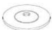
Pressure Plate (x1)

M8 Desk Clamp
Screw (x1)

Desk Clamp Bracket (x1)

5mm Allen Key (x1)
TOOLS REQUIRED:
- Power Drill
- 10mm (0.38") Drill Bit
• Phillips-head Screwdriver
Hardware

Bolt Through Washer (x1)

M8x30mm Screw (x1)

Base Casting (x1)

(Optional) Security Screw (x1)

3mm Allen Key (x1)

Cable Ball

Cable Clip
NOTE: Quantity for:
SD-DP-420 (x2 each)
SD-DP-750 (x4 each)
SD-DP-1150 (x6 each)


M4x10mm (x4)
M4x12mm (x4)
M4x16mm (x4)
Display Mounting Screws
IMPORTANT INFORMATION:
! IMPORTANT - Install Spacedec Donut Pole as per Installation Instructions.
! Each Quickshift Donut supports a maximum weight of 12kg (26.5lbs)
- Donut Pole 420mm supports a total of 12kg (26.5lbs).
- Donut Pole 750mm supports a total of 24kg (53lbs).
• Donut Pole 1150mm supports a total of 36kg (79.5lbs).
! This product supports VESA mounting hole configurations: 75x75mm and 100x100mm.
! The manufacturer accepts no responsibility for incorrect installation.
Step 1. Check Components
Check you have received all parts against the component checklist and Hardware above.
Step 2. Mounting Options
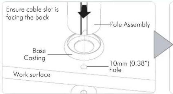
Option A. Bolt Through (Suits desktop thicknesses of 12mm - 40mm [0.5" - 1.5"])
Drill a 10mm (0.38") hole in the work surface at the desired position and assemble as shown.
Note: It is recommended that the pole assembly be mounted towards the rear edge of the work surface.

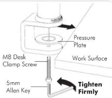
Option B. Desk Clamp (Suits desktop thicknesses of 12mm - 38mm [0.5" - 1.5"])
Attach the Desk Clamp Bracket to the bottom of the Pole Assembly using the M8 x 30mm Screw.
Tighten Firmly using
the 5mm Allen Key. Ensure the Spacedec Logo on the Base Casting is facing the front as shown.

Attach the Donut Pole Assembly using the Desk Clamp as shown.
Note: Desk Clamp suits 12mm (0.5") - 38mm (1.5") thick work surfaces.
Adjust the height of the Pressure Plate to suit your work surface.
Step 3. Attach the VESA Plate to your Display

Step 4. Attach your Display to the Quickshift Mount

flowchart
graph LR
    A["Hook the top of the VESA plate onto the Quickshift Mount."] --> B["Press and hold the Release Buttons. Gently push bottom of VESA Plate into Quickshift Mount. Release Buttons to lock in place."]
    B --> C["PUSH Release Button"]
    C --> D["(Optional) Insert the Security Screw, and tighten using a Phillips-head Screwdriver."]
    D --> E["TIGHTEN"]
    E --> F["Security Screw"]
Step 5. Adjust the height of the Quickshift Donut

flowchart
graph LR
    A["Open the lever to loosen the Quickshift Donut."] --> B["Slide the Quickshift Donut to desired position."]
    B --> C["If necessary, adjust the tension between the Donut and the Pole using the 5mm Allen Key supplied."]
    C --> D["TIGHTEN LOOSEN"]
    D --> E["Close the lever to lock the Quickshift Donut in place."]
    E --> F["CLOSE"]
Step 6. Adjust the VESA Ball Mount
Position your Display to the desired viewing angle using the ±20^ tilt allowed by the VESA Ball Mount.
If the display does not hold its position, or is too resistant, adjust the Tension Plate located at the rear of the VESA Ball Mount.
To make any adjustments, use the 3mm Allen Key supplied. Apply half a turn at a time to each screw on the Tension Plate to adjust evenly.
Check the display, and the adjust again if necessary.

Step 7. Cable Management
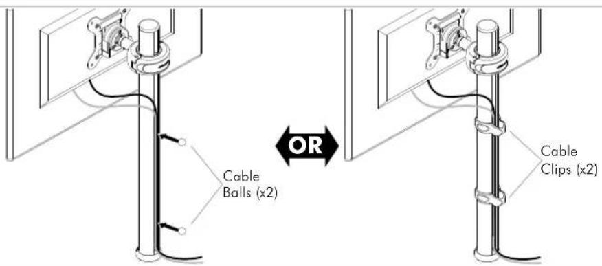
Connect cables to your Displays, routing them down to the rear of the poles.
Push the cables into the slots, using either the Cable Balls or Cable Clips to secure them to the pole as shown.
Note: Ensure enough slack is left in cables to allow for movement. When the slot in each pole cannot be used, use the supplied Cable Clips to secure the cables.
Installation Complete
Brand : Atdec
Model : SD-DP-1150
Category : Mounting bracket