
AWMS-NDB - Mounting bracket Atdec - Free user manual and instructions
Find the device manual for free AWMS-NDB Atdec in PDF.

| Product Type | Monitor Arm / Notebook Tray Mount |
| Brand | Atdec |
| Model | AWMS-NDB (System) Components: AWM-FF, AWM-LB, AWM-AD, AWM-HN |
| Mounting Type | F-Clamp (desk thickness 0-36mm normal, 36-79mm inverted) |
| Weight Capacity (Flat Monitor) | 0 - 9 kg (0 - 20 lbs) |
| Weight Capacity (Curved Monitor) | 0 - 6 kg (0 - 13.5 lbs) |
| Weight Capacity (Notebook Tray) | 0 - 8 kg (0 - 18 lbs) |
| VESA Compatibility | 75x75mm, 100x100mm (adapter for other sizes sold separately) |
| Rotation Range | 360° (default), can be limited to 180° |
| Tilt Adjustment | Yes, adjustable tilt tension |
| Arm Tension Adjustment | Yes, with Allen key and tension gauge |
| Cable Management | Integrated cable routing through arm |
| Tools Required | Phillips head screwdriver, 4mm and 5mm Allen keys |
| Materials | Aluminum and steel (estimated) |
| Dimensions (Arm) | Not specified; arm length approximately 300-500mm (estimated) |
| Weight (System) | Approx. 2-3 kg (estimated) |
| Power Supply | None (mechanical mount) |
| Maintenance | Periodic tension check; no lubrication required |
| Safety Features | Weight limit labels; security screw to prevent tray dislodgement |
| Warranty | Not specified; typical 5-10 years for premium mounts (estimate) |
Frequently Asked Questions - AWMS-NDB Atdec
User questions about AWMS-NDB Atdec
0 question about this device. Answer the ones you know or ask your own.
Ask a new question about this device
Download the instructions for your Mounting bracket in PDF format for free! Find your manual AWMS-NDB - Atdec and take your electronic device back in hand. On this page are published all the documents necessary for the use of your device. AWMS-NDB by Atdec.
USER MANUAL AWMS-NDB Atdec
AWM Dynamic Notebook Arm

natural_image
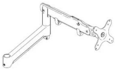
Technical line drawing of a mechanical arm with a panel mounted on top (no text or symbols)COMPONENT CHECKLIST
AWM-FF
F Clamp
(x1)

AWM-LB
Base (x1)
natural_image
Technical line drawing of a mechanical clamp or bracket assembly (no text or symbols)AWM-AD
Dynamic Arm (x1)
AWM-HN
AWM
Notebook Tray
(x1)

REQUIRED TOOLS
• Phillips Head Screwdriver
CONTENTS
| F Clamp | AWM-FF |
| Page 2 | | Component Checklist + Clamp Installation |
| Base | AWM-LB |
| Page 3 | | Component Checklist + Base Installation |
| Dynamic Arm | AWM-AD |
| Page 4 | | Component Checklist + Arm Installation |
| AWM Notebook Tray | AWM-HN |
| Page 4 | | Component Checklist + Tray Installation |
IMPORTANT INFORMATION
! Please ensure this product is installed as per these installation instructions.
! Do not remove/ throw away the plastic cap on the base.
! This product is compatible with Atdec AWM Series products.
! Curved monitors, deep devices (such as all-in-one PCs) and offset VESA locations exert additional leverage that can exceed the capacity of the mount even though the monitor weight may be within the stated range.
! The manufacturer accepts no responsibility for incorrect installation.
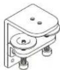
COMPONENT CHECKLIST

natural_image
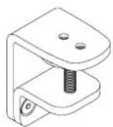
Technical line drawing of a metal bracket with two holes and a labeled section (A), no text or symbols present.Upper Clamp (x1)

natural_image
Technical line drawing of a mechanical clamp or bracket with a circular top and threaded base (no text or symbols)B
Lower Clamp
(x1)

C
Screw M8 x 16mm (x2)
D
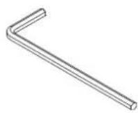
5mm Allen key (x1)
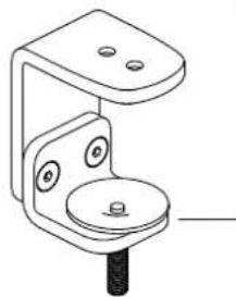
1. Attach base to upper clamp
2. Attach lower clamp to upper clamp
2.1 Measure the worksurface thickness and choose the suitable lower clamp position
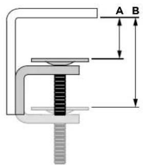

A - Normal
0 - 36mm
(0.00 - 1 ^3/8 )
natural_image
Technical line drawing of a mechanical bracket with mounting holes and a central screw (no text or symbols)B - Inverted
36 - 79mm
(1 3/8" - 3")
2.2 If using inverted position change the screw direction of the lower clamp
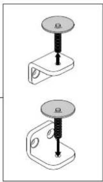
natural_image
Two mechanical clamps with threaded pins, shown from different angles (no text or symbols)2.3 Attach lower clamp to upper clamp in the suitable position using the two provided screws. (Normal position shown here)

natural_image
Mechanical assembly diagram showing a turning tool with rotational arrow (no text or symbols)Note: If there is only a small gap behind the worksurface, perform Step 3.1 before this step.
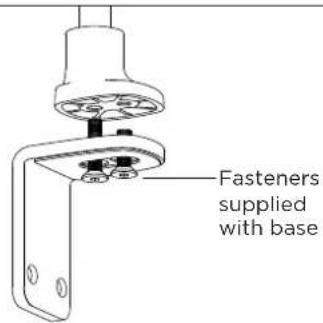
3. Fit fixing to work surface
3.1 Place in desired location on worksurface
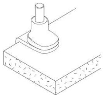
natural_image
Technical line drawing of a mechanical component with a cylindrical shaft and base plate (no text or symbols)3.2 Screw in pressure plate and tighten firmly.

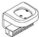
COMPONENT CHECKLIST

natural_image
Line drawing of a mechanical component with a cylindrical shaft and flange (no text or symbols)A
Base (x1)

B
Screw M8 x 16mm (x1)

C
Screw M8 x 30mm (x1)
1. Attach Base to Fixing

1.1 Follow the F Clamp installation guide on pages 2 of this booklet or provided with your alternate fixing option.
Supplied

F Clamp
AWM-FF
Also Compatible

Bolt Through Kit
AWM-FB
Heavy Duty F Clamp AWM-FH
C Clamp
AWM-FC
Grommet Clamp AC-GC
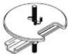
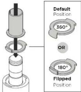
2. Set arm rotation to 180^ (optional)
Note: default arm rotation is set to rotate 360°
2.1 Remove plastic sleeve.
natural_image
Technical line drawing of a mechanical component with a cylindrical top and flanged base (no text or symbols)2.2 To remove rotation ring press down on front edge and lift.

2.3 Replace rotation ring in the desired orientation and replace plastic sleeve.

3. Fit arm onto Base
3.1 Push arm onto base, grub screw must be backed off at this time.
3.2 Ensure arm is fully pushed onto base. 3.3 Tighten set screw.

natural_image
Technical line drawing of a mechanical component with two views (✓ and ✕) showing different mounting features (no text or symbols present)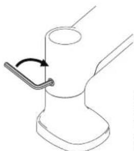
natural_image
Line drawing of a mechanical component with a curved arrow indicating rotation (no text or symbols)NOTE: Check the arm pan adjustment is smooth after tightening.
COMPONENT CHECKLIST

B
VESA
head
(x1)

C
Screw
M4x25mm
(x4)

D
Screw
M4x16mm
(x4)

E
Screw
M4x12mm
(x4)

F
Spacer
(x4)

G
Security
screw
(x1)

H
4mm
allen key
(x1)
WEIGHT RANGE
Flat Monitors
0 - 9kg (0 - 20lbs)
Curved Monitors
0 - 6kg (0 - 13.5lbs)
Display weight should be within the weight range of all modular elements that make up the complete display mounting solution.
AWM Notebook Tray
AWM-HN
COMPONENT CHECKLIST

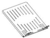
natural_image
Line drawing of a folded paper or document with vertical lines and corner brackets (no text or symbols)A Notebook Tray (x1)

B
Hook-and-Loop
Fasteners
(x4)
WEIGHT RANGE
0 - 8kg (0 - 18lb)
Device weight should be within the weight range of all modular elements that make up the complete display mounting solution.
1. Set arm rotation to 180^ (optional)
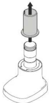
1.1 Remove plastic sleeve.

1.2 Remove rotation ring.

1.3 Place rotation ring in the desired position. The tag on the ring should always face towards the user.
2. Fit arm onto Base
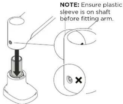
2.1 Push arm onto shaft.
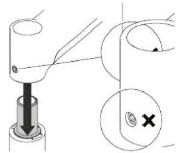
natural_image
Technical diagram showing a mechanical assembly with a downward arrow and a magnified inset of a circular component (no text or symbols)2.2 Ensure arm is fully pushed onto shaft.
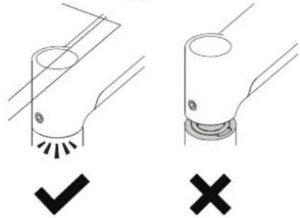
natural_image
Two mechanical components with checkmark and cross symbols, no text or labels present2.3 Tighten joint screw.

natural_image
Diagram of a mechanical joint or pipe fitting with a curved arrow indicating rotation (no text or symbols)Note: Check the arm rotation is smooth after tightening.
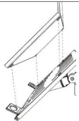
3. Mount Notebook Tray onto arm
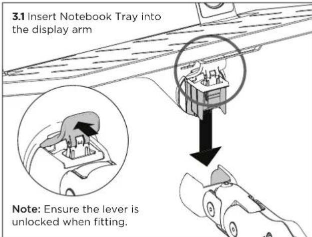
3.2 Ensure that the Notebook Tray is seated fully into the receptacle at the end of the display arm. There should be no gap.

3.3 Push the lever down to secure it to the arm assembly.

natural_image
Diagram of a hand pressing down on a mechanical component with a downward arrow indicating motion (no text or symbols)4. Mount notebook computer

4.2 To increase stability, use the self adhesive Hook-and-Loop Fasteners supplied.
a. Peel off the backing paper to the fasteners.
b. Attach fasteners to both the Notebook Tray and notebook computer.
c. Ensure that each set of fasteners are correctly aligned i.e. Hook to Loop.
natural_image
Technical line drawing of a mechanical assembly with no visible text or symbols5. Adjust tilt tension & install security screw
5.1 Use the allen key to adjust the tilt tension until the tray holds in a vertical position at the end of the arm.
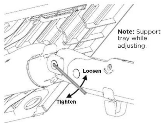
5.2 (Optional) Tilt the head upwards to install the optional security screw.

natural_image
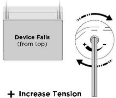
Technical line drawing of a mechanical assembly with no visible text or symbols6. Adjust arm tension
6.1 To accurately set the tension of the arm, position the device at 90 degrees

6.2 Use the allen key to adjust the arm tension to the weight of the device. Follow steps 6.3 to 6.5 to set the tension.

6.3 If the device sags or falls down, increase the arm tension by rotating the screw clockwise.
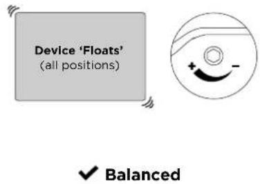
6.4 If the device springs upwards from the bottom position, decrease the arm tension by rotating the screw anti-clockwise.

6.5 If the device floats or hovers in all positions the arm tension is balanced and does not require further adjustment.
7. Tension gauge
7.1 When installing multiple devices of a similar weight, use the tension gauge to make installation faster.

natural_image
Technical line drawing of a mechanical clamp or bracket assembly (no text or symbols)Arm Tension Gauge
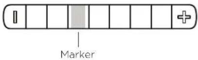
-
Set up one device and record the position of the marker on the gauge.
-
When installing subsequent displays, pre-tension the arm to the recorded amount, then fine-tune the tension by following steps 6.3 to 6.5.
8. Cable management
8.1 Plug cables into the device and route the cables down the arm using the cable hooks and clips.
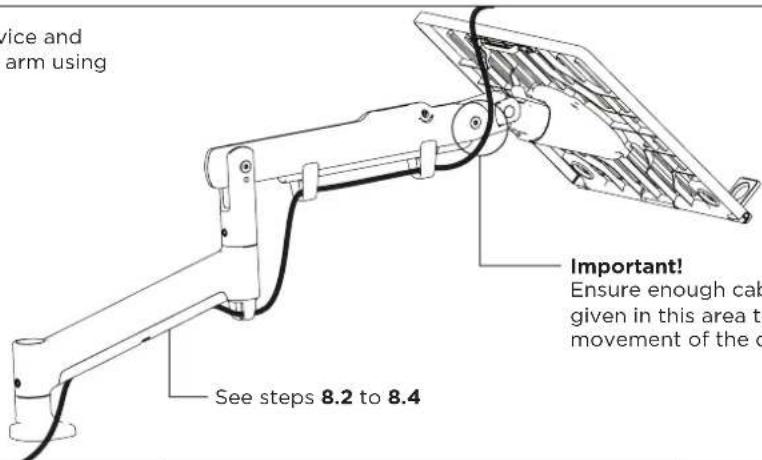
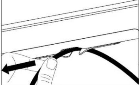
8.2 Wedge cable into the central gap and slide it down the arm.
8.3 The cable should slip into the arm cavity
8.4 Slide the remaining loose cable from the central gap up the arm.
natural_image
Line drawing of a hand holding a cable with a black cable inserted, no text or symbols present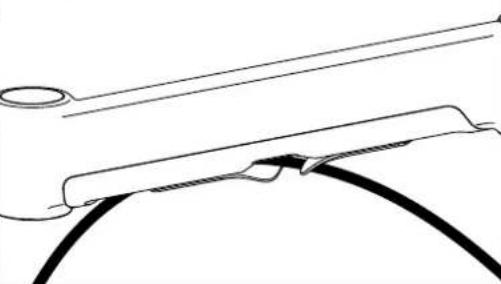
natural_image
Pure technical line drawing of a mechanical component or bracket (no text or symbols)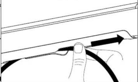
natural_image
Line drawing of a hand holding a cable with an arrow indicating direction (no text or symbols)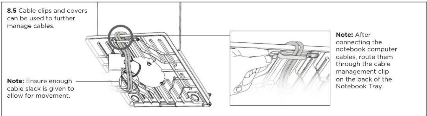
9. Adjust Notebook Tray
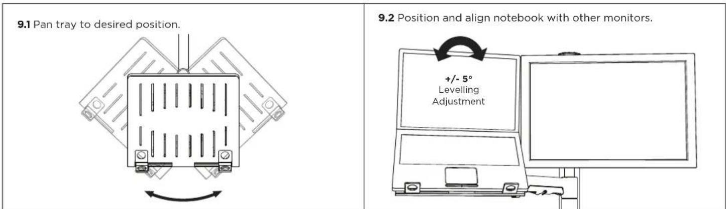
You may choose to convert your solution to mount a display, to do so:
| 10.1 VESA mounting compatibility 100mm 75mm 100mm 75mm Note: For other sizes, use a suitable adaptor plate (sold separately). | 10.2 Attach VESA head onto display with provided screws. Note: Spacers may be required for curved, recessed or uneven display surfaces. | 10.3 Be sure to use correct screw length 5mm 12mm Flush Spacer Too long Too short |
| 10.4 Insert VESA head into the display arm Display arm | 10.5 Ensure that the VESA head sits flush within the display arm. There should be no gap. Gap No Gap | 10.6 Push the lever down to secure it to the arm assembly |

- AWM Dynamic Notebook Arm
- IMPORTANT INFORMATION
- Attach base to upper clamp
- Attach lower clamp to upper clamp
- Fit fixing to work surface
- Attach Base to Fixing
- Set arm rotation to 180° (optional)
- Fit arm onto Base
- WEIGHT RANGE
- Flat Monitors
- Curved Monitors
- AWM Notebook Tray
- Set arm rotation to 180° (optional)
- Fit arm onto Base
- Mount Notebook Tray onto arm
- Mount notebook computer
- Adjust tilt tension & install security screw
- Adjust arm tension
- Tension gauge
- Cable management
- Adjust Notebook Tray
Brand : Atdec
Model : AWMS-NDB
Category : Mounting bracket