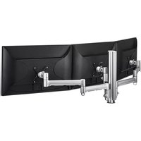
AWMS-3-13714-C - Mounting bracket Atdec - Free user manual and instructions
Find the device manual for free AWMS-3-13714-C Atdec in PDF.


| Product Type | Monitor Mounting Arm Kit |
| Model | AWMS-3-13714-C |
| Brand | Atdec |
| Configuration | 1 x 130mm Arm + 2 x 710mm Arms + 400mm Post + C-Clamp |
| Weight Capacity (per arm) | 0 - 12 kg (0 - 26.5 lbs) |
| VESA Compatibility | 75x75mm, 100x100mm (adapters for other sizes sold separately) |
| Mounting Options | C-Clamp, Bolt-Through, F-Clamp, Grommet (fixings sold separately) |
| Desk Thickness (C-Clamp) | 18 mm - 33 mm (0.7" - 1.3") |
| Arm Rotation | 360° (can be set to 180°) |
| Tilt Adjustment | Yes, with tension adjustment using Allen key |
| Cable Management | Integrated cable clips and removable cable covers |
| Materials | Aluminum, Steel |
| Dimensions (Post) | Height: 400 mm |
| Dimensions (Arms) | 130 mm (short), 710 mm (long) |
| Included Tools | 4mm and 5mm Allen keys, screws |
| Safety Features | Security screw to prevent monitor detachment |
| Compatibility | Atdec AWM Series modular components |
| Installation | Easy to follow step-by-step manual, all tools supplied |
| Maintenance | Periodically check screw tightness; clean with damp cloth |
| Spare Parts | Available separately: arms, posts, clamps, VESA heads |
Frequently Asked Questions - AWMS-3-13714-C Atdec
User questions about AWMS-3-13714-C Atdec
0 question about this device. Answer the ones you know or ask your own.
Ask a new question about this device
Download the instructions for your Mounting bracket in PDF format for free! Find your manual AWMS-3-13714-C - Atdec and take your electronic device back in hand. On this page are published all the documents necessary for the use of your device. AWMS-3-13714-C by Atdec.
USER MANUAL AWMS-3-13714-C Atdec
1 x 130 Arm and 2 x 710 Arm on 400 Post with C-Clamp

COMPONENT CHECKLIST RANGE



A
AWM-A13
130 Arm
(x1)
B
AWM-A71
710 Arm
(x2)
C
AWM-P40
400 Post
(x1)
D
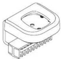
AWM-FC
C-Clamp
(x1)
CONTENTS
| C-Clamp | AWM-FC |
| Page 2 | Component Checklist |
| Page 3 | Clamp Installation |
| 400 Post | AWM-P40 |
| Page 6 | Component Checklist |
| Page 7 | Post Installation |
| 130 Arm | AWM-130 |
| Page 8 | Component Checklist |
| Page 9 | Arm Installation |
| Page 10 | Monitor Installation |
| Page 11 | Cable Management |
| 460 Arm | AWM-460 |
| Page 12 | Component Checklist |
| Page 13 | Arm Installation |
| Page 14 | Monitor Installation |
| Page 15 | Cable Management |

COMPONENT CHECKLIST REQUIRED TOOLS

A
C Clamp Bracket (x1)

C
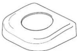
Cover for Post (x1)
E
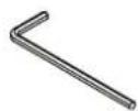
4mm Allen key (x1)

B
C Clamp Plate (x1)
D
Cover for Base (x1)

F
5mm Allen key (x1)
- All tools supplied
IMPORTANT INFORMATION
! Please ensure this product is installed as per these installation instructions.
! This product is compatible with Atdec modular (AWM) products.
! The manufacturer accepts no responsibility for incorrect installation.
1. C Clamp overview
1.1 Default - This is the "out of the box" configuration

MIN THICKNESS - 25mm (1") MAX THICKNESS - 33mm (1 5 / 16 )
1.2 Inverted - The C Clamp can be reconfigured for thicker surfaces

MIN THICKNESS - 18mm (1/8") MAX THICKNESS - 25.8mm (1")
2. Re-configure Clamp
2.1 Slide pad off

2.3 Invert pad
![graph TD A["Process Step"] --> B["Output"] style A fill:#fff,stroke:#000 style B fill:#fff,stroke:#000](/content/2026/06/1204827/images/c1b6d8b8145344a1312ebcc05d720cae9cc5dbc9b5bd478979f8f292a7732273.jpg)
2.3 Slide pad back on

3. Post mount configuration
3.1 Attach plate to post

3.2 Place in desired location

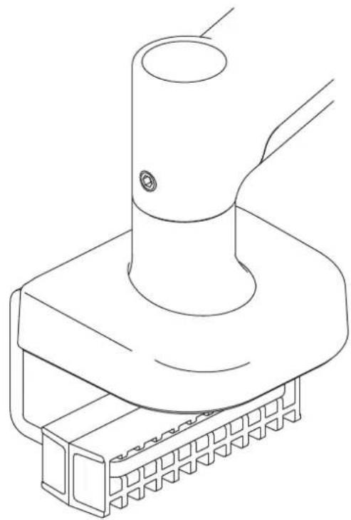
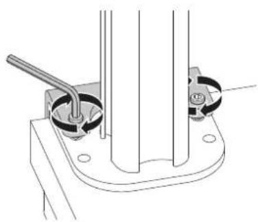
3.3 Slide the C Clamp bracket over the plate and position screw tips in the indents on the base plate

Note: You may need to un-screw the set screws out of the plate using the allen key
3.4 Check the set screws are mounted in position. Also check the desk clamp bracket is positioned tight up against the mounting surface edge

3.5 Tighten the set screws firmly and evenly on both sides of the desk clamp bracket.
4. Installing the clamp cover to post
4.1 Remove the cable cover by pulling it straight up and out of the post. Remove top cap if already installed
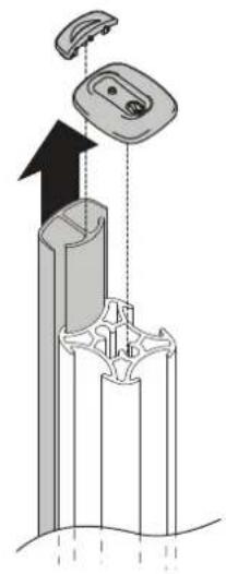
4.2 Locate the C Clamp cover over the post. Guide over the holes in the base plate and gently apply pressure on the cover until it clicks into place
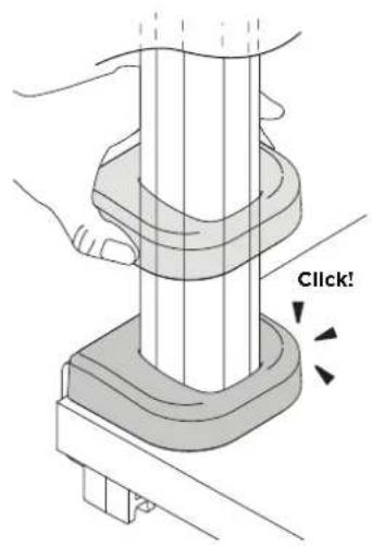
4.3 Re-attach the cable cover by sliding it into the post channel. Fit the pole and cover caps back on.

5. Base mount installation
5.1 Attach plate to base

5.2 Place the base and plate in desired location
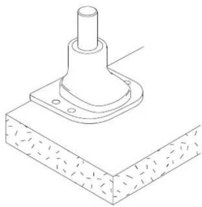
5.3 Slide the bracket onto the base plate and position screw tips in the indents on the base plate
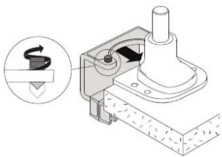
Note: You may need to un-screw the set screws out of the plate using the allen key
5.4 Check the set screws are mounted in position. Also check the desk clamp bracket is positioned tight up against the mounting surface edge

5.5 Tighten the set screws firmly and evenly on both sides of the desk clamp bracket

6. Installing the clamp cover to base
6.1 Locate the Cover for Base over the base. Guide over the holes in the base plate and gently apply pressure on the cover until it clicks into place.

6.2 Installation Complete
To continue with installation of your monitor arm, refer to your monitor arm's installation guide.


COMPONENT CHECKLIST

A
Post (x1)

B
Post Cap (x1)

C
Screw M8 (x2)
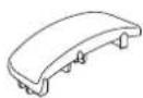
D
Cable Cover Cap (x1)
(not supplied with all posts)

E
Cable Cover (x1) (not supplied with all posts)
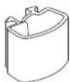
F
Cable clips
(not supplied
with all posts)

REQUIRED TOOLS
- All tools provided
IMPORTANT INFORMATION
! Please ensure this product is installed as per these installation instructions.
! This product is compatible with Atdec AWM Series products.
! The manufacturer accepts no responsibility for incorrect installation.
1. Attach Post to fixing (fixing sold separately)
1.1 Follow the installation guide provided with your fixing to attach it to the post and fit it to the worksurface.

AWM Fixing options
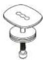
Bolt Through Kit
AWM-FB

F Clamp
AWM-FF

Heavy Duty
F Clamp
AWM-FH

C Clamp
AWM-FC

Grommet Clamp AC-GC
2. Check post placement & arm positions
2.1 Do not mount a monitor arm on the rear channel of a post when the post is fixed to the desk using an F Clamp, Heavy Duty F Clamp, or C Clamp.
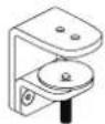
F Clamp
AWM-FF

Heavy Duty
F Clamp
AWM-FH

C Clamp
AWM-FC

3. Cable cover position and post cap
3.1 To reposition the cable cover, pull it straight up and out of the post and insert it into any of the available channels
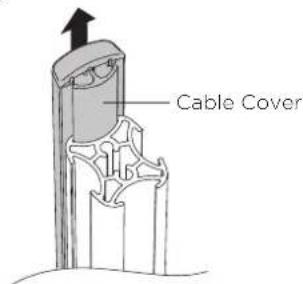
Note: The cable cover shown does not come with all posts
3.2 Optional cable cover positions

3.3 Fit post cap onto the top of the post

Allen Key
Post Cap
Note: An allen key may be stored in the Post Cap.
Post
4. Cable clips and cover
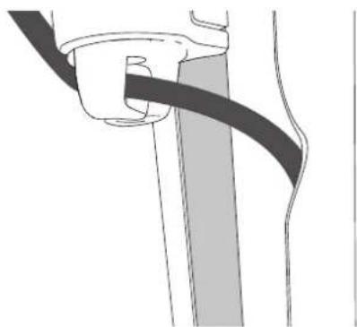
4.1 Push the cable down into the cable clip.
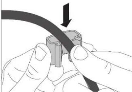
Note: Cable clips do not come with all posts. Additional clips sold separately.
4.2 Insert one side of the cable clip into the channel on the post assembly, then push in the other side.

4.3 Loop cable and insert into cable cover.

4.4 Feed remaining cable into the cover.

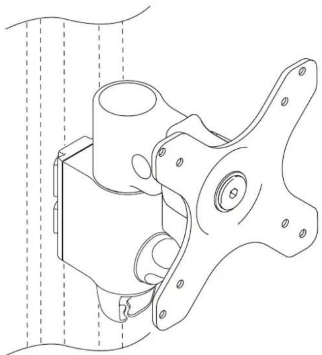
COMPONENT CHECKLIST

A
Monitor Arm (x1)

B
VESA Head
(x1)

D
Screw
M4x25mm
(x4)

E
Screw M4x16mm (x4)

F
Screw M4x12mm (x4)

C
Post Clamp
(x1)

G
Spacer (x4)

H
Security screw (x1)

|
4mm
allen key
(x4)

REQUIRED TOOLS
• Phillips Head Screwdriver
WEIGHT RANGE
0 - 12kg (0 - 26.5lbs)
IMPORTANT INFORMATION
! Please ensure this product is installed as per these installation instructions.
! The manufacturer accepts no responsibility for incorrect installation.
! This product is compatible with Atdec AWM Series products.
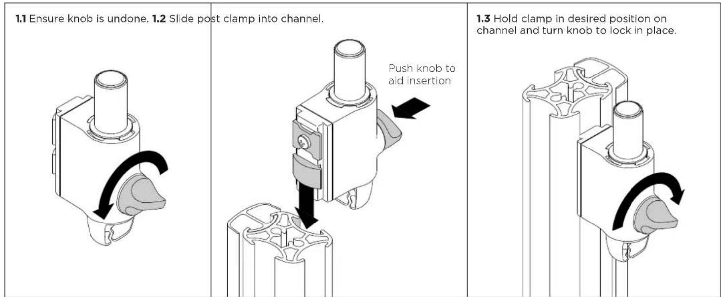
1. Fix clamp to Post or Wall Channel
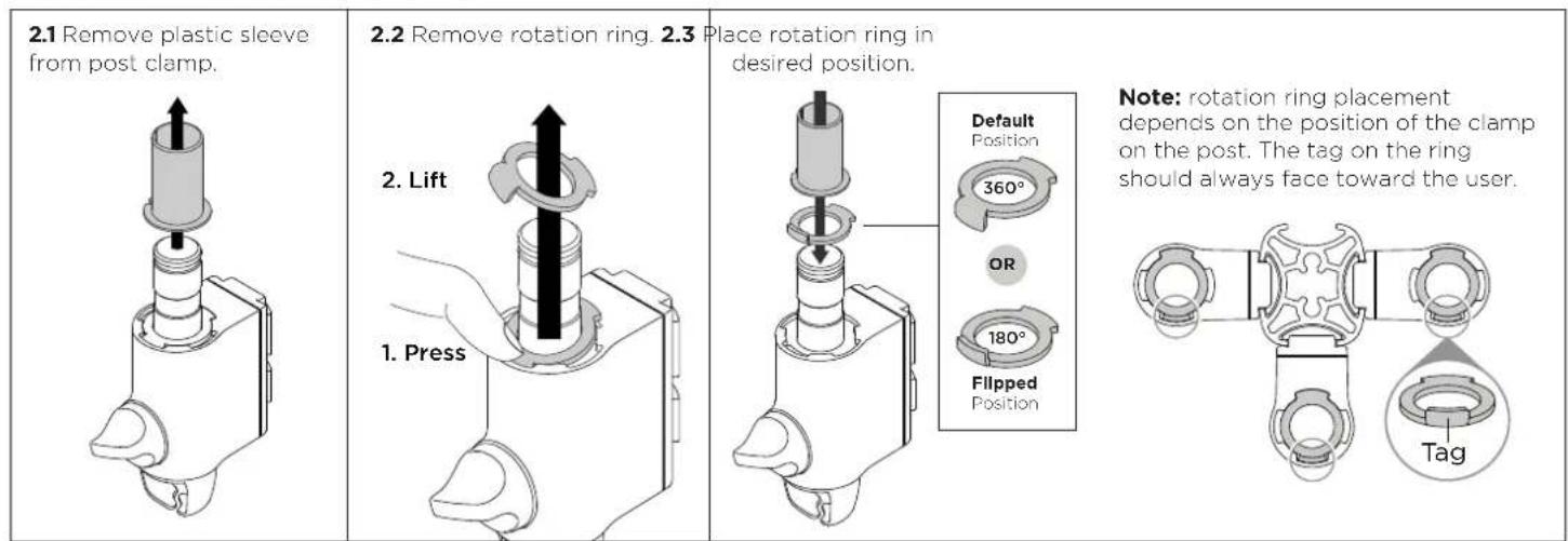
2. Set arm rotation to 180° (optional)
Note rotation is set to 360° by default.
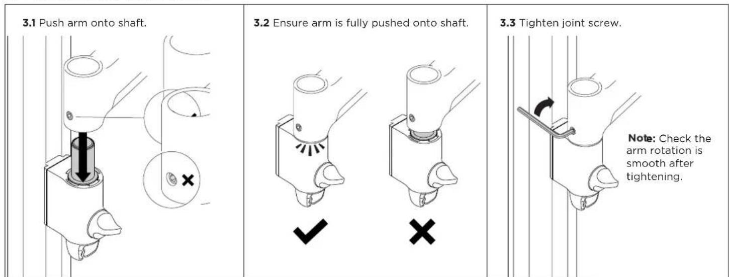
3. Fit arm onto post clamp
4. Attach VESA head to monitor
4.1 VESA mounting compatibility

Note: For other sizes, use a suitable adaptor plate (sold separately).
4.2 Screw the VESA head onto monitor

Note spacers may be required for curved, recessed or uneven monitor surfaces.
4.3 Ensure the correct screw length is used to attach the monitor.

5. Mount monitor
5.1 Insert VESA head into the monitor arm

5.2 Ensure that the VESA head sits flush within the monitor arm. There should be no gap

5.3 Push the lever down to secure it to the arm assembly

6. Adjust tilt tension & Install security screw
6.1 Use the allen key to adjust the tilt tension until the monitor holds in a vertical position at the end of the arm.

6.2 OPTIONAL security screw
To install the optional security screw tilt the head upwards

6. Monitor arm cable management
6.1 Plug cables into the monitor and route the cables down the arm using the cable hooks and clips.

Important:
Ensure enough cable slack is given to allow for movement of the monitor
7. Post cable management
7.1 Push the cable down into the cable clip

7.2 Push cable clip into post channel

7.3 Recommended post cable cover position for double or triple arm set-ups

7.4 To reposition the cable cover, pull it straight up and out of the post and insert it into any of the available channels

Note: The cable cover shown does not come with all posts
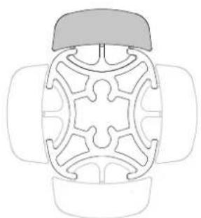
Alternative cable cover positions
7.5 Loop cable and insert into cable cover

7.6 Feed remaining cable into cover


COMPONENT CHECKLIST

A
Monitor Arm (x1)

B
VESA Head (x1)

C
Post Clamp
(x1)


E
Screw
M4x16mm
(x4)
F
Screw
M4x12mm
(x4)
D
Screw
M4x25mm
(x4)


G
Spacer
(x4)
H
Security
screw
(x1)
|
4mm
allen key
(x1)

REQUIRED TOOLS
• Phillips Head Screwdriver
WEIGHT RANGE

0 - 12kg (0 - 26.5lbs)
IMPORTANT INFORMATION
! Please ensure this product is installed as per these installation instructions.
! The manufacturer accepts no responsibility for incorrect installation.
! This product is compatible with Atdec AWM Series products.
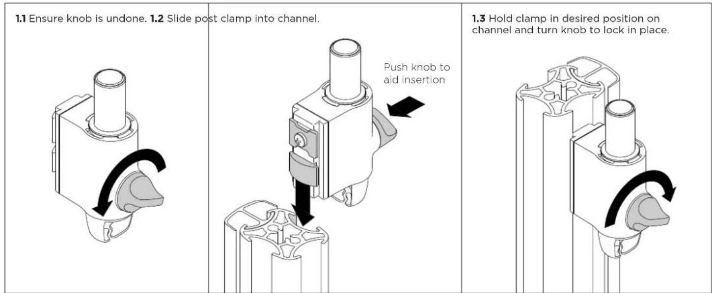
1. Fix clamp to Post or Wall Channel
2. Set arm rotation to 180° (optional)
Note rotation is set to 360° by default.

3. Fit arm onto post clamp

4. Attach VESA head to monitor
4.1 VESA mounting compatibility
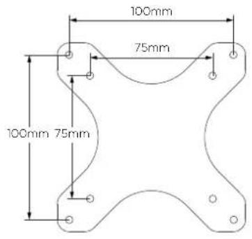
Note: For other sizes, use a suitable adaptor plate (sold separately).
4.2 Screw the VESA head onto monitor

Note spacers may be required for curved, recessed or uneven monitor surfaces.
4.3 Ensure the correct screw length is used to attach the monitor.

5. Mount monitor
5.1 Insert VESA head into the monitor arm

5.2 Ensure that the VESA head sits flush within the monitor arm. There should be no gap
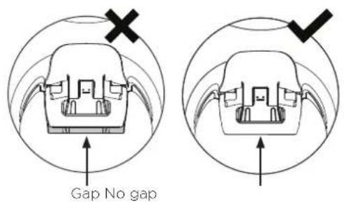
5.3 Push the lever down to secure it to the arm assembly

6. Adjust tilt tension & Install security screw
6.1 Use the allen key to adjust the tilt tension until the monitor holds in a vertical position at the end of the arm.
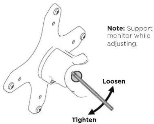
6.2 OPTIONAL security screw
To install the optional security screw tilt the head upwards

6. Monitor arm cable management
6.1 Plug cables into the monitor and route the cables down the arm using the cable hooks and clips

7. Post cable management
7.1 Push the cable down into the cable clip

7.2 Push cable clip into post channel

7.3 Recommended post cable cover position for double or triple arm set-ups

7.4 To reposition the cable cover, pull it straight up and out of the post and insert it into any of the available channels
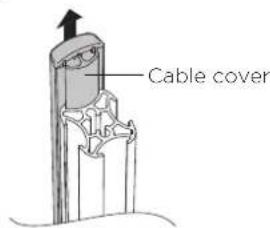
Note: The cable cover shown does not come with all posts

Alternative cable cover positions
7.5 Loop cable and insert into cable cover
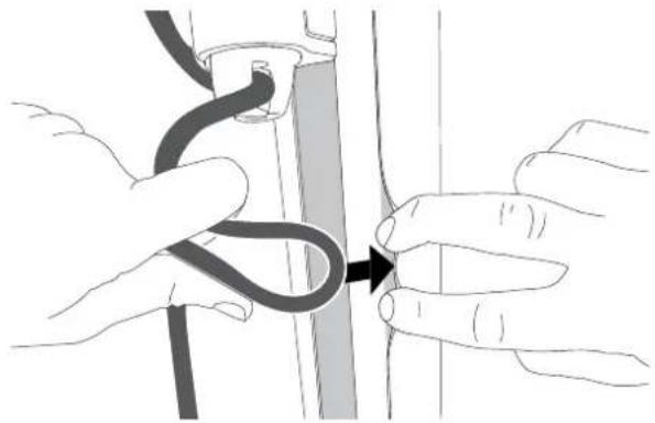
7.6 Feed remaining cable into cover

- 1 X 130 ARM AND 2 X 710 ARM ON 400 POST WITH C-CLAMP
- COMPONENT CHECKLIST REQUIRED TOOLS
- IMPORTANT INFORMATION
- C CLAMP OVERVIEW
- RE-CONFIGURE CLAMP
- POST MOUNT CONFIGURATION
- INSTALLING THE CLAMP COVER TO POST
- BASE MOUNT INSTALLATION
- INSTALLING THE CLAMP COVER TO BASE
- 6.2 INSTALLATION COMPLETE
- REQUIRED TOOLS
- ATTACH POST TO FIXING (FIXING SOLD SEPARATELY)
- CHECK POST PLACEMENT & ARM POSITIONS
- CABLE COVER POSITION AND POST CAP
- CABLE CLIPS AND COVER
- WEIGHT RANGE
- FIX CLAMP TO POST OR WALL CHANNEL
- SET ARM ROTATION TO 180° (OPTIONAL)
- FIT ARM ONTO POST CLAMP
- ATTACH VESA HEAD TO MONITOR
- MOUNT MONITOR
- ADJUST TILT TENSION & INSTALL SECURITY SCREW
- MONITOR ARM CABLE MANAGEMENT
- POST CABLE MANAGEMENT
Brand : Atdec
Model : AWMS-3-13714-C
Category : Mounting bracket