
Quasar CB-6204 - Security Camera FLIR - Free user manual and instructions
Find the device manual for free Quasar CB-6204 FLIR in PDF.


| Product Type | IP Security Camera |
| Brand | FLIR |
| Model | Quasar CB-6204 |
| Resolution | 4K UHD (3840 x 2160 pixels) |
| Sensor Type | 1/2.5-inch CMOS Sensor |
| Lens | Motorized lens 4.3 – 8.6 mm, F1.4 |
| Field of View | Horizontal: 100° – 50°; Vertical: 55° – 28° |
| Night Vision | Up to 30 meters with IR LED |
| IP Rating | IP67 |
| Dimensions (L x H x D) | 80 x 80 x 200 mm |
| Weight | 1.4 kg |
| Power Supply | PoE (Power over Ethernet) IEEE 802.3af |
| Power Consumption | 12 W maximum |
| Connectivity | Ethernet 10/100/1000 Base-T, RJ45 |
| Storage | MicroSD up to 256 GB, NVR compatible |
| Motion Detection | Built-in artificial intelligence (person, vehicle detection) |
| Audio | Built-in microphone and speaker, two-way audio |
| Operating Temperature | -40°C to +60°C |
| Mounting | Wall or ceiling mount (included) |
| Warranty | 2 years |
| Package Contents | Camera, mount, screw kit, quick installation guide |
| Care and Cleaning | Clean the lens with a dry microfiber cloth; avoid harsh solvents |
| Security | HTTPS encryption, ONVIF protocol, password-protected user access |
| Spare Parts and Repairability | Contact FLIR customer service for original parts |
| General Information | High-performance network camera for outdoor surveillance |
Frequently Asked Questions - Quasar CB-6204 FLIR
User questions about Quasar CB-6204 FLIR
0 question about this device. Answer the ones you know or ask your own.
Ask a new question about this device
Download the instructions for your Security Camera in PDF format for free! Find your manual Quasar CB-6204 - FLIR and take your electronic device back in hand. On this page are published all the documents necessary for the use of your device. Quasar CB-6204 by FLIR.
USER MANUAL Quasar CB-6204 FLIR
DVTEL INC. 65 Challenger Road Ridgeeld Park, NJ 07660
Quasar
by dvtel
Quasar CB-6204 Quasar CB-6208 IP Bullet Camera User and Installaon Guide
The contents of this guide may not be reproduced or reprinted in whole or in part without the express written permission of DVTEL, Inc.
dvtel ® Now you can.
Rev. 03
March 12, 2015
Table of Contents
1 Document Informaon......v
2 Overview....1
2.1 Features....2
2.2 Package Contents .... 3
3 Introducon to the CB-620x IP Bullet Camera ....4
3.1 Typical CB-620x Camera 4
3.2 Camera Dimensions....4
3.3 Internal Connectors....5
3.4 System Cable Connectors....5
3.4.1 Waterproong the Camera Cable Connectors....6
3.4.2 Connecng the Unit to the Network....8
3.4.3 Connecng Power to the Camera 8
3.4.4 Input and Output Connectors 9
4 System Requirements....11
5 Installaon....13
5.1 Indoor Installaon 13
5.2 Outdoor Installaon 13
5.3 Power and Ethernet Cable Connecon 14
5.4 Inial Camera Conguraon 14
5.5 Mounng Instrucons....15
5.5.1 Eliminang IR Reecon 15
5.5.2 Mounng the Camera 16
5.5.3 Installing the Camera 17
6 Using the DNA Utility to Search and Access the Camera 19
7 Conguring Communicaton Sengs on the Quasar Camera 21
8 Adjusting and Framing-Up the Camera View 25
9 Conguraon and Operaon....27
9.1 Browser-Based Viewer Introducon 27
9.2 Live Screen....29
9.3 System Sengs....31
9.3.1 System.... 31
9.3.2 Security....33
9.3.3 Network....42
9.3.4 Events Setup....52
9.3.5 Edge Recording....65
9.3.6 Moon Detecon....71
9.3.7 Schedule 75
9.3.8 File Locaon 76
9.3.9 Maintenance 77
9.3.10 Import/Export 85
9.4 Streaming Sengs....86
9.4.1 Video Format....87
9.4.2 Video Compression 96
9.4.3 Video ROI Encoding....98
9.4.4 Video OCX Protocol 99
9.4.5 Video Frame Rate....100
9.4.6 Video Mask....101
9.4.7 Audio 102
9.5 Camera Sengs....103
9.5.1 Exposure.... 104
9.5.2 Picture Adjustment 112
9.5.3 Advanced Picture Sengs.... 113
9.5.4 IR Funcon 117
9.5.5 Miscellaneous.... 119
9.6 Log Out 120
10 Appendices....121
A.1. CB-6204 Technical Specicaons 122
A.2. CB-6208 Technical Specicaons 125
A.3. Internet Security Setngs....128
A.4. Install UPnP Components....130
A.5. Deleng the Exisng DVPlayer 132
A.6. Deleng Temporary Internet Files....133
A.7. Mounng Accessories 134
Contacng DVTEL....135
List of Figures
Figure 1: Package Contents....3
Figure 2: CB-620x Series Camera....4
Figure 3: CB-620x Series Camera Dimensions....4
Figure 4: MicroSD Card Drive and Reset Button....5
Figure 5: CB-620x Camera Input/Output Connections 5
Figure 6: Camera Cables....6
Figure 7: System Cable....6
Figure 8: System Cable Hose and Wiring....7
Figure 9: RJ45 Connector and Plug....7
Figure 10: Thread-Lock Sealing Nut and RJ45 Connector 7
Figure 11: Loosened Thread-Lock Sealing Nut 7
Figure 12: RJ45 Connector and Thread-Lock Sealing Nut......8
Figure 13: Fastened Thread-Lock Sealing Nut 8
Figure 14: Discovered IP Devices....14
Figure 15: DNA Assign IP Dialog Box....15
Figure 16: Screw Holes on Mounting Base....17
Figure 17: Mounting Base Rotation Screw 17
Figure 18: Repositioning the Camera 18
Figure 19: Windows Firewall Screen 21
Figure 20: Discovered IP Devices....21
Figure 21: DNA Assign IP – Use DHCP Dialog Box 22
Figure 22: DNA Assign IP – Static IP Dialog Box 22
Figure 23: Installing the ActiveX Control....23
Figure 24: Security Window 23
Figure 25: Browser-Based User Interface....27
Figure 26: Live View Screen 29
Figure 27: Live Video Info Dialog Box....29
Figure 28: System Section Tabs....31
Figure 29: System Screen....32
Figure 30: User Screen 33
Figure 31: Edit User Account Dialog Box....34
Figure 32: HTTPS Screen – Create Self-Signed Certificate 35
Figure 33: Create Self-Signed Certificate Dialog Box....36
Figure 34: Installed Certificate Section 36
Figure 35: Certificate Properties 37
Figure 36: HTTPS Screen – Upload Signed Certificate....37
Figure 37: HTTPS Screen – Install Signed Certificate....38
Figure 38: Create Certificate Request Dialog Box 38
Figure 39: Created Request Subject....39
Figure 40: Certificate Request Properties Dialog Box 39
Figure 41: IP Filter Screen 40
Figure 42: IEEE 802.1X/EAP-TLS Screen....41
Figure 43: Network > Basic Screen 42
Figure 44: QoS Screen 44
Figure 45: SNMP Settings Screen 45
Figure 46: UPnP Screen 47
Figure 47: Direct Access to Camera with UPnP Enabled 47
Figure 48: DDNS Screen 48
Figure 49: Mail Screen – SMTP 49
Figure 50: FTP Screen....50
Figure 51: HTTP Screen....51
Figure 52: IO Screen....52
Figure 53: Upload Image by FTP 53
Figure 54: Send HTTP Notification 54
Figure 55: Record Video Clip....54
Figure 56: Upload Image by E-Mail 54
Figure 57: Network Failure Detection Screen....56
Figure 58: Tampering Screen 57
Figure 59: Day/Night Trigger Screen 60
Figure 60: Periodic Event Screen 61
Figure 61: Manual Trigger Screen 63
Figure 62: SD Card Screen....65
Figure 63: Video File Recording List....66
Figure 64: Selected File Window 67
Figure 65: Network Share Screen....67
Figure 66: Video File Recording List....68
Figure 67: Selected File Window 69
Figure 68: Recording Screen 70
Figure 69: Motion Detection Screen 71
Figure 70: Motion Detection Screen – with Schedule Drop-Down Menu 72
Figure 71: Motion Window without Detection....72
Figure 72: Motion Window with Detection....73
Figure 73: Pixel Interval Illustration....73
Figure 74: Schedule Screen....75
Figure 75: File Location Screen 76
Figure 76: Log File Screen....77
Figure 77: User Information Screen – Get User Information 78
Figure 78: User Information – Get User Privacy 79
Figure 79: Factory Default Screen 80
Figure 80: Partial Restore Screen....81
Figure 81: Software Version Screen 82
Figure 82: Upgrade Screen....82
Figure 83: Software Upgrade – In Process....83
Figure 84: Parameter Screen....84
Figure 85: Import/Export Screen 85
Figure 86: File Download Screen....85
Figure 87: Streaming Section Tabs 86
Figure 88: CB-6204 Video Format Screen....87
Figure 89: CB-6208 Video Format Screen....88
Figure 90: View-1 (Source) 94
Figure 91: View-2 Image Rotated Vertically (Reversed)....94
Figure 92: CB-6204 Video Compression Screen....96
Figure 93: Video Compression Screen 97
Figure 94: Video ROI Encoding Screen....98
Figure 95: Video OCX Protocol Screen 99
Figure 96: Video Frame Rate Screen 100
Figure 97: Mask Screen....101
Figure 98: Audio Screen 102
Figure 99: Camera Section Tabs 103
Figure 100: CB-6204 Exposure Screen 105
Figure 101: CB-6208 Exposure Screen 109
Figure 102: Camera Settings Screen – Picture Adjustment 112
Figure 103: Advanced Picture Settings Screen – White Balance.... 113
Figure 104: Advanced Picture Settings Screen – Backlight 114
Figure 105: Advanced Picture Settings Screen – WDR Function.... 115
Figure 106: Advanced Picture Settings Screen – Noise Reduction.... 116
Figure 107: IR Function Screen 117
Figure 108: Camera Settings Screen – Digital Zoom 119
Figure 109: Login Message....120
Figure 110: Login Window 120
Figure 111: Command Bar Toolbar – Select Internet Options.... 128
Figure 112: Internet Options Screen....128
Figure 113: Command Bar Toolbar – Internet Options....129
Figure 114: Schedule Screen 129
1 Document Informaon
Document Conventions
WARNING and CAUTION notes are distributed throughout this document, whenever applicable, to alert you of potentially hazardous situations. These may be hazards associated with a task or a procedure you are carrying out or are about to carry out.
The following document convenons are used throughout this manual:
Conventions relatives au document
A Warning is a precautionary message that indicates a procedure or condition where there are potential hazards of personal injury or death.
A Cauon is a precautionary message that indicates a procedure or condition where there are potential hazards of permanent damage to the equipment and or loss of data.
A Note is useful informaon to prevent problems, help with successful installaon, or to provide additional understanding of the products and installaon.
A Tip is informaon and best pracces that are useful or provide some benet for installaon and use of DVTEL products.
Document Scope and Purpose
The purpose of this document is to provide instrucons and installaon procedures for physically connecng the Quasar Gen II camera. Aer compleng the physical installaon, additional setup and conguraons may be required before video analysis and detecon can commence.

Note:
This document is intended for use by technical users who have a basic understanding of CCTV camera/video equipment and LAN/WAN network connecns.
Remarque:
Installaon must follow safety, standards, and electrical codes as well as the laws that apply where the units are being installed.
Averssement:
Proprietary Rights and Non-Disclosure
This manual is delivered subject to the following restricons and condions:
This document contains proprietary informaon belonging to DVTEL, Inc. This informaon is supplied solely for the purpose of assisng explicitly the licensee of the DVTEL units.
- No part of this document contents may be used for any other purpose, disclosed to any third party or reproduced by any means, electronic or mechanical, without the express prior written permission of DVTEL, Inc.
Trademarks and Copyrights
DVTEL, the DVTEL logo, Quasar Gen II, CB-6204, and Latude are trademarks of DVTEL, Inc. Products and trademarks menoned herein are for idencaon purposes only and may be registered trademarks of their respective companies. DVTEL, Inc. makes no representaons whatsoever about any other products or trademarks menoned in the manual.
This manual and its contents herein are owned by DVTEL, Inc. © DVTEL, Inc. 2015. All rights reserved.
Disclaimer
Users of DVTEL products accept full responsibility for ensuring the suitability and considering the role of the product detecon capabilities and their limitaon as they apply to their unique site requirements.
DVTEL, Inc. and its agents make no guarantees or warranes to the suitability for the users' intended use. DVTEL, Inc. accepts no responsibility for improper use or incomplete security and safety measures.
Failure in part or in whole of the installer, owner, or user in any way to follow the prescribed procedures or to heed WARNINGS and CAUTIONS shall absolve DVTEL, Inc. and its agents from any resulting liability.
Specicaons and informaon in this guide are subject to change without noce.
Document Conventions
WARNING and CAUTION notes are distributed throughout this document, whenever applicable, to alert you of potenally hazardous situations. These may be hazards associated with a task or a procedure you are carrying out or are about to carry out.
The following document convenons are used throughout this manual:
Conventions relatives au document
General Cautions and Warnings
This secon contains informaon that indicates a procedure or condion where there are potenal hazards. These may be hazards associated with a task or procedure a user is carrying out or about to carry out. WARNINGS and CAUTIONS are distributed throughout this document, whenever applicable, to alert the user of potenally hazardous situations.
SAVE ALL SAFETY AND OPERATING INSTRUCTIONS FOR FUTURE USE.
Although the unit is designed and manufactured in compliance with all applicable safety standards, certain hazards are present during the installation of this equipment.
To help ensure safety and to help reduce risk of injury or damage, observe the following:
- The camera covers is an essenal part of the product. Do not open or remove it.
- Never operate the camera without the cover in place. Operating the camera without the cover poses a risk of re and shock hazards.
- Do not disassemble the camera or remove screws. There are no user serviceable parts inside the unit.
- Only qualified trained personnel should service and repair this equipment.
- Observe local codes and laws and ensure that installaon and operaon are in accordance with re, security and safety standards.
Averssement:
To avoid damage from overheang or unit failure, assure that there is sucient temperature regulaon to support the unit's requirements (cooling/heang). Operang temperature should be kept in the range specied for the product (0° to 50°C/32° to 122°F), with no more than 90% non-condensing humidity.
Aenon:
Electrical Safety Notice and Warnings

Warning:
- Read the installaon instrucons before you connect the unit to a power source.
- Electrical safety should always be observed. All electrical connexons must be performed by a cered electrician.
- Use the supplied power supply and protect against stac electricity, ground faults and power surges.
- The unit uses a three-wire power cord to make sure that the product is properly grounded when in use. This is a safety feature. If the intended power outlet does not support three prongs, one of which is a ground, contact an electrician to install the appropriate outlet. NEVER remove or otherwise aempt to bypass the ground pin of the power cord. Do not operate the unit in the absence of a suitably installed ground conductor.
- If you use an extension cord with this system, make sure that the total ampere rang on the products plugged into the extension cord does not exceed the extension cord ampere rang.
- To avoid possible shock hazards or damaging the unit, assure that the positive and negative of the power leads are properly connected to the terminal block connector before plugging it into the unit or turning on the power source.
-
In the following situations, the electric power should be turned o immediately and appropriate repairs, replacements or remedies should be taken if:
-
The power line is damaged, frayed or shows heavy wear.
- The unit has been physically crushed or deformed.
- The unit has been exposed to water.
- The unit has been exposed to, or shows signs of damage from, re, intense heat, heavy smoke, fumes, or vapors.
- Electrical connecons of the unit become abnormally hot or generate smoke.
- The unit has been dropped, damaged or shows signs of loose internal parts.
- The unit does not operate properly.
Minimizing EMI and RFI
When wires run for a significant distance in an electromagnec eld, electromagnec interference (EMI) can occur. Strong EMI (e.g. lightning or radio transmiers) can destroy the units and can pose an electrical hazard by conducng power through lines and into the system. Poor quality or worn wiring can result in radio frequency interference (RFI). To minimize the eects of EMI and RFI, consult your reseller.
There are several requirements that should be properly addressed prior to installaon at the site. The following specicaons are requirements for proper installaon and operaon of the unit:
- Ambient Environment Condions: Avoid poisoning the unit near heaters or heang system outputs. Use proper maintenance to ensure that the unit is free from exposure to EMI.
- Accessibility: The locaon used should allow easy access to unit connecons and cables.
- Safety: Cables and electrical cords should be routed in a manner that prevents safety hazards, such as from tripping, wire fraying, overheang, etc. Ensure that nothing rests on the unit's cables or power cords.
- Ample Air Circulation: Leave enough space around the unit to allow free air circulaon.
- Cabling Consideraons: Units should be placed in locaons that are opmal for the type of video cabling used between the unit and the cameras and external devices. Using a cable longer than the manufacturer's speciaons for opmal video signal may result in degradaon of color and video parameters.
- Physical Security: The unit provides threat detection for physical security systems. In order to ensure that the unit cannot be disabled or tampered with, the system should be installed with security measures regarding physical access by trusted and un-trusted pares.
- Network Security: The unit transmits over IP to security personnel for video surveillance. Proper network security measures should be in place to assure networks remain operang and free from malicious interference. The unit is intended for installaon on the backbone of a trusted network.
- Electrostac Safeguards: The unit as well as other equipment connected to it (relay outputs, alarm inputs, racks, carpeng, etc.) shall be properly grounded to prevent electrostac discharge.
The physical installaon of the unit is the rst phase of making the unit operaonal in a security plan. The goal is to physically place the unit, connect it to other devices in the system, and to establish network connecvity.
2 Overview
The DVTEL Quasar Gen II CB-620x series consists of two camera families: CB-6204 and CB-6208.
The Quasar CB-6204 is an indoor/outdoor, vandal-proof, IP bullet camera. The camera provides real-me, QHD H.264 mul-streaming with the highest quality image, supporting three simultaneous video streams at QHD 1440p, HD 720p, and D1 resoluons. The family consists of two cameras with a varifocal, motorized, auto-focus, P-Iris lens with True Day/Night and infrared IR illuminator:
CB-6204-11-I includes a 3-8mm, F1.4 lens with 96-38° horizontal viewing angle
CB-6204-21-I includes a 7-22mm, F1.4 lens with 42-14° horizontal viewing angle
The Quasar CB-6208 is an indoor/outdoor, vandal-proof, IP bullet camera. The camera provides real-me, 4K, H.264 mul-streaming with the highest quality image, supporting four simultaneous video streams at UHD 2160p, Full HD 1080p, HD 720p, and D1 resoluons. The family consists of two cameras with a varifocal, motorized, auto-focus, F1.4, P-Iris lens with True Day/Night and infrared IR illuminator:
CB-6208-11-I includes a 3.5-8mm lens with 116-50° horizontal viewing angle
■ CB-6208-21-I includes a 9-22mm lens with 45-18° horizontal viewing angle

Cauon:
If you are using DVTEL Latude, we recommend that you congregate the camera's sengs via the AdminCenter. This is because the camera's web-based interface might be overwritten by Latude sengs. Refer to the Latude online help for informaon regarding congregate camera sengs.
Aenon:
• H.264 and MJPEG compression
- Edge moon detecon
• Detecon event driven alarms
• Built-in web applicaon/web server
- Dual HTTP nocaoon server support (up to two servers)
• 128GB microSDXC recording support
• SNMP v1/v2/v3 and SNMP traps
• Electronic day/night (ICR)
- Privacy masks
- ONVIF support
- Mulple users
- Tampering detecon and nocaon
• Vandal-proof IP66 enclosure
- HTTP streaming MJPEG
- Moon detecon with region of interest masking
- Alarm input driven events
- FTP upload
(up to two locaons)
- Send images on alarm to e-mail
- Record snapshots to microSDXC card on alarm
• Security IP restricted access allow/deny list
- Analog video output
- WDR and ATW
- RTSP support
- Group permissions
- Two encoder streams available
- Motorized lens
• Progressive scan CMOS sensor
- Historical moon detecon levels detected/recorded at frame levels
- Relay output acons on alarm
- Upload alarm images to FTP
• E-mail SMTP alarm nocaoon (up to two e-mails)
- Sequential snapshot numbering
- UPnP support
- BNC analog output
• 3DNR image noise reducon
• Supports PoE/12VDC/24VAC
• Per-user permissions
- Low-lux mode and backlight compensaon
• Infrared LED illuminator
2.2 Package Contents
Before proceeding, check that the box contains the items listed here. If any item is missing or has defects, do not install or operate the product. Contact your dealer for assistance.
 Bullet IP Camera(Includes system cable) Bullet IP Camera(Includes system cable) |  Power Terminal Block Power Terminal Block |
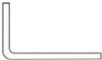 M4 Inner Hex Wrench (x1) M4 Inner Hex Wrench (x1) | 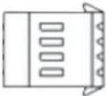 Alarm Terminal Block (x1) Alarm Terminal Block (x1) |
 Plastic Screw Anchor (x5) Plastic Screw Anchor (x5) |  M4 Self-Tapping Screw (x5) M4 Self-Tapping Screw (x5) |
 CD(Bundled software and documentation) CD(Bundled software and documentation) | Quick Installation Guide |
 Desiccant Desiccant |  User and Installation Guide User and Installation Guide |
Figure 1: Package Contents

Note:
The self-tapping screws are mainly for soer substrate/material installaon such as wood. For other installaon materials such as cement ceilings, it is necessary to pre-drill and use plasc anchors before fastening the supplied self-tapping screws into the wall.
Related Documentaon
• CB-620x Bullet Camera Quick Installaon Guide
• DNA 2.0 User Manual
• Desiccant User Guide
3 Introducon to the CB-620x IP Bullet Camera
This chapter provides informaon about the camera hardware for reference before installaon. The connectors included on the camera's system cable are described.
■ Typical CB-620x Camera
■ Camera Dimensions
■ Internal Connectors
■ System Cable Connectors
3.1 Typical CB-620x Camera
The gure below shows a typical CB-620x camera.

natural_image
Exterior view of a dvtel security camera (no text or symbols on body)Figure 2: CB-620x Series Camera
3.2 Camera Dimensions
The CB-620x series IP bullet camera dimensions are shown below.
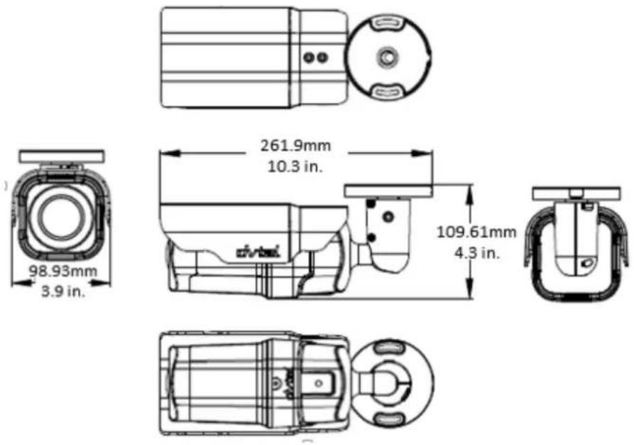
Figure 3: CB-620x Series Camera Dimensions
3.3 Internal Connectors
The camera's microSD card drive and reset buon are inside the camera housing.
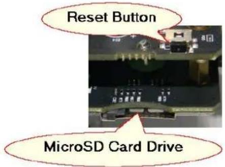
Figure 4: MicroSD Card Drive and Reset Buon

Note:
Desiccant is included inside the camera housing and must be replaced every me the housing is opened. Aer desiccants are replaced, reconnect the front housing to the camera as soon as possible. Otherwise, the desiccant will become damp and cannot be used. For instrucons on removing the desiccant, refer to the Desiccant User Guide.
To perform a hard reset to full factory defaults using the Reset buon
- Press a pointed object against the black switch on the Reset buon.
- Press the buon for 30 seconds. Both LEDs on the RJ45 connector are exguished. Aer one second, the green network LED ashes once and remains lighted. The yellow acvity LED ashes as soon as it detects network acvity. The unit returns to full factory defaults.
3.4 System Cable Connectors
The camera is shipped with a system cable for network, power, I/O, and audio connexons. The gure below shows the various connectors included in the system cable of the camera. The connectors, pin numbers and signal denions are listed below.

Figure 5: CB-620x Camera Input/Output Connecons
| No. | Cable | Pin | Denion | Remarks | |
| 1 | RJ45 | - | For network and PoE connecons | ||
| 2 | Power (DC 12V*/AC 24V) (3-pin Terminal Block) | 1 | DC 12V - | AC 24V 1 | Power conncon |
| 2 | Reserved | GND | |||
| 3 | DC 12V + | AC 24V 2 | |||
| 3 | Alarm I/O (4-pin Terminal Block) | 1 | Alarm In - | Alarm conncon | |
| 2 | Alarm In + | ||||
| 3 | Alarm Out - | ||||
| 4 | Alarm Out + | ||||
| 4 | Audio I/O | Green | Audio Out | Two-way audio transmission | |
| Pink | Audio-in/Mic-in | ||||
| 5 | BNC | - | For analog video output | ||
3.4.1 Waterproong the Camera Cable Connectors
Follow the instrucons below to waterproof the connectors for the dierent types of cables included in the system cable. The cables are shown below.

natural_image
Coiled black cable with three colored connectors (pink, green, purple) against a plain white background, no text or symbols visible.System Cable
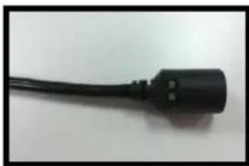
natural_image
Close-up of a black electrical plug with two terminals (no text or symbols visible)RJ45 Cable

natural_image
Close-up of a black cable with a connector tip, isolated on white background (no text or symbols visible)IP66 RJ45 Cable
Figure 6: Camera Cables
To waterproof the system cable
- Connect all the required devices to the system cable.
- Coat the joints with silicone gel. There should be no gap between the connectors and the cables. For alarm I/O connector and power connector, make sure the side with wires aached is also sealed with silicone gel.

natural_image
Close-up of multiple colored electronic connectors with wires, no visible text or symbolsFigure 7: System Cable
- Seal the end of the rubber coang of the system cable as indicated in the gure below. Use enough silicone gel to II in the hose and wrap around each wire in order to properly waterproof the cable.

natural_image
Close-up of a black cable with exposed wires and a red dashed circle highlighting a junction (no text or symbols)Figure 8: System Cable Hose and Wiring
3.4.1.2 RJ45 Cable
To waterproof the RJ45 cable
- Plug the Ethernet cable to the connector of the RJ45 cable.

natural_image
Close-up of a black electrical plug with a red dashed circle highlighting a connector (no text or symbols visible)Figure 9: RJ45 Connector and Plug
- Coat the joint with silicone gel. Make sure there is no gap between the Ethernet cable and the connector in order to properly waterproof the cable.
3.4.1.3 IP66-Rated RJ45 Cable
To waterproof the IP66-Rated RJ45 cable
- Remove the supplied connector from the IP66-rated RJ45 plug.

Figure 10: Thread-Lock Sealing Nut and RJ45 Connector
- Loosen the thread-lock sealing nut on the IP66-rated RJ45 plug.

natural_image
Close-up of a black and silver electrical plug connector (no text or symbols visible)Figure 11: Loosened Thread-Lock Sealing Nut
- Thread the Ethernet cable through the thread-lock sealing nut and the IP66-rated RJ45 plug. If the Ethernet cable is already aached to a connector, remove it rst.

Figure 12: RJ45 Connector and Thread-Lock Sealing Nut
- Carefully remove a secon of rubber coang from the end of the Ethernet cable to reveal the wires.
- Inset the wires into the correct pins of the connector.
- Plug the Ethernet cable into the connector of the IP66-rated RJ45 cable.
- Fasten the RJ45 plug to the connector of the IP66-rated RJ45 cable.
- Tighten the thread-lock sealing nut to the plug.

natural_image
Close-up of a black electrical plug with a cable, no visible text or symbolsFigure 13: Fastened Thread-Lock Sealing Nut
3.4.2 Connecng the Unit to the Network
To ensure transmission quality, cable length should not exceed 100 meters (328 feet). Connect one end of the Ethernet cable to the RJ45 connector of the system cable, and plug the other end of the cable to the network switch or PC. Check the status of the link and the acvity LEDs. If the LEDs are unlit, check the LAN conncon.

A steady green link LED indicates good network conncon.
The yellow acvity LED ashes to indicate network acvity.
3.4.3 Connecng Power to the Camera
The camera can be powered by Power over Ethernet or by an external 12VDC/24VAC adaptor (not included in the package).
- If using an external power supply, connect the power leads or three-pin power terminal block to the power supply.
■ If using PoE, make sure that a Power Sourcing Equipment (PSE) device is used in the network
Make sure the camera's power cable is properly connected. All electrical work must be performed in accordance with local regulatory requirements.
3.4.4 Input and Output Connectors
The alarm input and output connectors are shown below.
| Pin No. | Designation |  |
| 1 | Input (-) | |
| 2 | Input (+) | |
| 3 | Output (-) | |
| 4 | Output (+) |
4 System Requirements
To access the camera via a web browser, ensure that your PC has the proper network conneccon and meets system requirements as described below.
| Item | Minimum System Requirement |
| Personal Computer | Minimum: Intel® CoreTM i5-2430M @ 2.4 GHz, 4GB RAMRecommended: Intel® CoreTM i7-870 @ 2.93 GHz, 8GB RAM |
| Operang System | Windows XP, Windows 7, Windows 8, Windows 8.1 |
| Web Browser | Microso Internet Explorer 9, 10, or 11 |
| Network Card | 10BaseT (10 Mbps), 100Base-TX (100 Mbps), or 1000BaseT (1000Mbps) operaon |
| Viewer | AcveX control plug-in for Microso IE |
5 Installaon
Follow the instrucons below for indoor and outdoor installaon of the camera.
Related Links
- Indoor Installaon
• Outdoor Installaon
• Power and Ethernet Cable Connecon
- Inial Camera Conguraon
- Mounng Instrucons
5.1 Indoor Installaon
Read the instrucons provided in this chapter thoroughly before installing the camera. Following are additional consideraons for indoor installaon:
- There must be a fuse or circuit breaker at the starng point of the electrical wiring infrastructure.
- For indoor installaons, such as industrial applicaons, the camera must be protected from hosle external elements (e.g. corrosive environment, metallic dust, extreme temperatures, soot, over spray, etc.).
- Do not place the camera on or near radiators and heat sources.
■ All electrical work must be performed in accordance with local regulatory requirements.
5.2 Outdoor Installaon
Read the instrucons provided in this chapter thoroughly before installing the camera. Following are additional consideraons for outdoor installaon:
- For outside wiring installaon, always use weatherproof equipment, such as boxes, receptacles, connectors, etc.
- For electrical wiring, use the properly rated sheathed cables for condions to which the cable will be exposed (for example, moisture, heat, UV, physical requirements, etc.).
- Plan ahead to determine where to install infrastructure weatherproof equipment. Whenever possible, ground components to an outdoor ground.
- Use best security pracces to design and maintain secured camera access, communicaons infrastructure, tamper-proof outdoor boxes, etc.
- All electrical work must be performed in accordance with local regulatory requirements.
5.3 Power and Ethernet Cable Connecon
Make sure the camera's power cable is properly connected. Refer to System Cable Connectors. If using Power over Ethernet (PoE), make sure Power Sourcing Equipment (PSE) is available on the connected network. All electrical work must be performed in accordance with local regulatory requirements.
5.4 Inial Camera Conguraon
To perform the initial camera conguraon
- Unpack the camera.
- Connect one end of the network Cat 5 Ethernet cable to the RJ45 connector on the camera's system cable.
- Connect the other end of the network cable to a Power Sourcing Equipment (PSE) device, such as a switch.
-
Verify that the LEDs on the RJ45 connector illuminate green (indicang a stable network conncon) and ashing yellow (to indicate network acvity).
-
Do the following:
a. Copy and run dna.exe (see note below) from the included CD.

Note:
DNA is an enhanced soware alternate to Device Search. Either of these programs may be used. They are supplied on the included CD.
b. Click the icon.
c. Select the unit requiring IP assignment.

Figure 14: Discovered IP Devices
d. Right-click the mouse and select the assigned IP address or click the Assign IP button to open the DNA Assign IP dialog box.

Note:
The camera default IP Address and the subnet mask IP Address are automacally supplied by the DHCP server.
e. In the dialog box that is displayed, enter values for the IP Address, Gateway and Netmask.
f. Click Update and wait for OK status to be displayed.
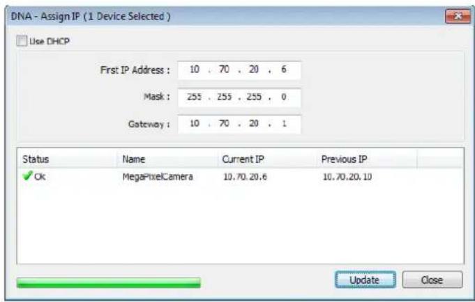
Figure 15: DNA Assign IP Dialog Box
g. Disconnect the Ethernet cable. The camera is ready for deployment (moung) in a site installaon.

Note:
- The camera can be connected to a PC for bench installaon via an Ethernet cross-cable.
- The camera default IP Address is automatically set by the DHCP server. If using Latude, the Address must be set manually.

Tip:
A camera setup adapter, such as Veracity Pinpoint, can be used to connect a laptop directly to the camera when using PoE.
5.5 Mounng Instrucons
The camera can be installed directly on a wall or ceiling with the integrated three-axis adjustable bracket mount.

Note:
The wall or ceiling must have enough strength to support the camera.
5.5.1 Eliminang IR Reecon
To eliminate IR reecon
- Clean the protective lens cover on the camera housing from dirt and nger prints.
- Make sure the lens cover has no scratches.
- Avoid aiming the IR where there are nearby objects closer than the scene of interest which might react back into the lens.
5.5.2 Mounng the Camera
To mount the camera, follow one of these procedures:
■ For indoor/outdoor installaons:
a. On the ceiling/wall/at surface, install a security camera wall mount bracket stand that is sturdy enough to hold the camera in a xed posion for the eld of view required.
b. Screw the bracket/stand to the mounng socket on the boom of the camera.
c. Connect the system cable to the network, power, I/O devices, and audio devices, as required for your site. See System Cable Connectors (page 5).
■ For bracket, pole and pendant installaons:
a. Feed the system cable through the mounng accessory.

Note:
The power cable is not required if using PoE.

Tip:
Even if you are not using alarm inputs and audio input/output at the me of installaon, you may want to consider pre-wiring these connecons for future use. Use shims for shoring up mounts on uneven surfaces.
b. Check that the installaon is not imsy, will not wobble, and is ush with the mounng surface.
c. Plug the network Cat 5 cable into the camera's Ethernet port.
d. Do one of the following:
- If using an external power supply, plug the power terminal block into the power supply terminals.
- If using PoE, connect the other end of the Cat 5 cable to the network and turn on the power from the power supply.
e. If applicable, wire the Alarm In, Alarm Out, Audio In, and Audio Out terminal blocks to external devices.
5.5.3 Installing the Camera
To install the camera
- Place the camera at the installaon locaon.
- Place the supplied template on the surface where you will install the camera.
- On the ceiling or wall, mark the posion of the two screw holes on the base of the moung bracket.

natural_image
Close-up of a white industrial device with two red-circled ports, no visible text or symbolsFigure 16: Screw Holes on Mounng Base
- At the center of the marked holes, draw a cable entry hole with 30 mm (1.2") diameter/15 mm (0.6") radius.
- Drill the cable entry hole.
- Drill a hole slightly smaller than the supplied plasc screw anchor on each marked screw hole.
- Insert the plasc screw anchors into the drilled holes.
- Thread the camera's system cable through the cable entry hole. Refer to System Cable Connectors (page 5) for cable connecons.
- Match the screw holes of the camera with the plasc screw anchors at the installaon locaon.
- Fasten the camera with the supplied M4x31 self-tapping screws.
- Loosen the screw circled below in order to rotate the camera at the base.

natural_image
Close-up of a white toilet or showerhead fixture with a red circle highlighting a small metallic button (no text or symbols visible)Figure 17: Mounng Base Rotaon Screw
- Loosen the two screws circled in the picture below in order to manipulate the camera posioning at the ball joint. The camera can be twisted and moved up and down at the ball joint.

natural_image
Close-up of a white toilet or showerhead with two metallic screws and a circular red annotation highlighting the screw (no text or symbols present)Figure 18: Repositioning the Camera
- Point the camera in the desired direcon and fasten the screws.
6 Using the DNA Utility to Search and Access the Camera
The DVTEL Network Assistant (DNA) is a user-friendly utility that is designed to easily discover and conjure DVTEL edge devices on a network. The DNA tool has a simple user interface and does not require any installaon. The soware is provided as a single, standalone executable. It runs on any PC.
DNA provides a central locaon for lisng all the DVTEL camera models accessible over the network. Once listed, each camera can be right-clicked to access and change the network sengs. If the network sengs are changed for some reason, a new search will relist the units. The units may then be congured via the web interface.
If DVTEL Latude is being used, congure the unit with a stac IP address rather than with DHCP. This ensures that the IP address will not automacally change in the future and interfere with conguraons and communicaon.
The camera must be made accessible for seng network addresses.

Note:
For detailed guidelines about DNA and its usage, refer to the DNA 2.0 User Manual, which is included in the CD provided with the camera.
7 Conguring Communicaon Setngs on the Quasar Camera
To congure communicaon sengs on the camera
- Connect the camera to the network on the same VLAN/LAN as the workstaon.
- If the network supports the default, open the DNA utility by running dna.exe which can be found in the DNA Utility folder in the supplied CD, or click the DNA icon .

Note: DNA is an alternate soware to Device Search. Either of these programs may be used.
- In the DNA applicaon, click the DNA buon.
- If the Windows Firewall is enabled, a security alert window pops up.
- To connue, click Allow Access. Latude users should consult the Latude Installaon Instrucons on disabling the Windows Firewall.
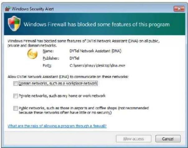
Figure 19: Windows Firewall Screen
- Click Assign IP. All the discovered IP devices will be listed in the page, as shown in the gure below. The camera's default IP Address is automatically supplied by the DHCP server.

Figure 20: Discovered IP Devices
- Right-click the camera whose network property is to be changed. From the context menu that opens, select Assign IP. The Assign IP dialog is displayed.

Figure 21: DNA Assign IP – Use DHCP Dialog Box

Tip: Record the camera's MAC address for future reference.
- To access DNA, do one of the following:
a. For DHCP (not supported by Latitude):
i. Select Use DHCP. Do not use for Latude.
ii. Click Update and wait for status.
b. For Stac IP (recommended for Latude users):
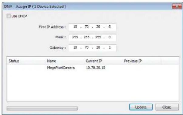
Figure 22: DNA Assign IP – Stac IP Dialog Box
i. Do not select the Use DHCP checkbox. This is recommended for security purposes and for and Latude users. In the IP Address, Gateway, and Netmask, enter the respective LAN/VLAN (oponal DNS) values.
ii. Click Update and wait for OK status to be displayed.
-
Right-click and select Web to directly access the camera via a web browser. The default web browser opens and requests access to the camera IP address.
-
When the web browser contacts the camera IP, do the following:
a. Login using the default user name Admin and password 1234.

Note:
User name and password are case-sensitive.

Note:
It is strongly advised that administrator's password be altered for security reasons.
b. If the Informaon Bar (just below the URL bar) prompts for permission to install the AcveX Control for displaying video in the browser (see the gure below), right-click the Informaon Bar. Select Install AcveX Control to allow the installaon.

Figure 23: Installing the AcveX Control
If a security warning window prompt appears, click Install.

Figure 24: Security Window
- If a popup message appears for running the DVPlayer add-on, click Allow.

Note:
If the password is changed and DVTEL Latude AdminCenter Discovery feature is in use, deselect all other proprietary types. Select DVTEL Quasar Gen II Series so that the new password can be congured in the Discovery tab sengs.
Additionally, you can change the camera's network properes (either DHCP or Stac IP) directly from the camera's web interface on the System > Network > Basic screen.
8 Adjusting and Framing-Up the Camera View
Aer the camera is connected to the network and running, it is necessary to frame-up the scene and adjust the camera sengs to optimize the picture for the individual scenes. If Latude is being used, consider scheduling dierent sengs for changing ambient conditions throughout the day, week, month or seasons.
To adjust and frame-up the camera view
- In the DNA applicaon, click DNA.
- In the Discovery list, click to select the camera.
- Right-click the context menu and select Web, or enter the camera's IP address in your browser's URL address bar.
- When the browser connects to the camera and prompts for login, do the following:
a) Log in using the default user name Admin and password 1234. If the password has previously been changed, use the new password.

Note:
Both the user name and password are case sensitive.
b) Allow the AcveX to download and choose to install the DVTEL Web Player (DVPlayer).
c) Aer the unit's web interface opens, use the funcon buons on the Home page to adjust the zoom or focus.

Tip:
To view greater image detail for more accurate high-denion focusing, on the web-based Viewer home page, right-click the image, click Full Screen, and check the focus.

Note:
Best focusing results can be achieved when the lens iris is fully open (such as at night in low light). This prevents loss of sharpness if light levels are reduced at night.
- To achieve opmum focus results during dayme, open the Camera > Exposure screen in camera's web interface and select Auto Shuer mode. Save changes and complete the focusing steps. When nished, restore your exposure sengs as needed.
9 Conguraon and Operaon
The Quasar Gen II CB series camera is provided with a browser-based conguraon interface for video playback and recording. In this chapter, informaon about main page introducon, system related sengs and camera sengs are described in detail.
Additionally, if DVTEL's Latude VMS is used, many of the conguraons and features of DVTEL's VMS provide conguraon and automaon of the camera.
This secon includes the following informaon:
Live Screen
■ System Sengs
■ Streaming Sengs
■ Camera Sengs
- Logout
■ Browser-Based Viewer Introducon
9.1 Browser-Based Viewer Introducon
The gure below shows the Quasar Gen II CB-620x camera's browser-based user interface.
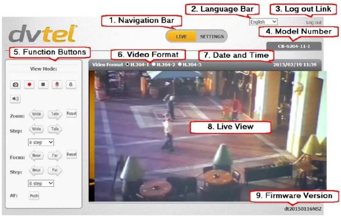
Figure 25: Browser-Based User Interface
The user interface displays the following informaon:
- The Navigaon Bar is displayed in the center of the screen containing Live and Sengs buons.
Live Buon
The Live screen opens by default when the camera logs on. It is used to monitor live video of the targeted area, adjust the display size, take snapshots of the view area, stop/start video streaming, record video in a designated le locaon, acvate or de-avcate a loudspeaker (audio funcon), and to perform a digital zoom. An explanaon of the items on the screen is included below and in secon 9.2.
■ Sengs Buon
Clicking the Seings buon opens the Sengs screen, whose sidebar which includes three tabs – System, Streaming, and Camera – that are used for to conjure system sengs.
- System Sengs
The administrator can congregate sengs for basic system parameters, security, network operation, events, recording, storage, system maintenance, and more. Details are discussed in System Sengs.
- Streaming Sengs
The administrator can modify video and audio sengs on this page. Details are discussed in Streaming Sengs.
- Camera Sengs
The administrator can adjust many of the camera sengs on this page, such as Exposure, Picture Adjustment, IR Funcon, Digital Zoom, and TV System. Details are discussed in Camera Sengs.
-
The Language Bar is displayed to the right of the Navigaon Bar. Supported languages include English, German, Spanish, French, Italian, Japanese, Korean, Portuguese, Russian, Simplified Chinese, and Tradional Chinese.
-
The Log out link is located to the right of the Language Bar. Click the Log Out link to exit the applicaon or log into the camera with a dierent username and password. See Log Out.
-
The camera model number is displayed under the Log out link.
-
Funcon buons are displayed to the le of the Live View window. These are discussed in the following secon.
-
The video format is displayed and can be selected to the le of the date and me.
-
The current date and me are displayed under the model number.
-
In the center of the interface is the Live View window, which displays the image that the camera is monitoring.
-
The rmware version of the camera is displayed under the Live View window on the right side.
9.2 Live Screen
The camera's Live screen is used to monitor live video.
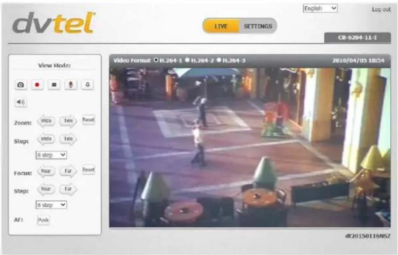
Figure 26: Live View Screen
Right-clicking the Live window opens the Info dialog box, which displays key details about the video stream:

Figure 27: Live Video Info Dialog Box
The View Mode area in the Live screen includes the following funcon buons:
Snapshot

Click this buon to automacally save the JPEG snapshots in the specied locaon. The default locaon to save snapshots is: C:.To change the storage locaon, refer to File Locaon.
Record/Pause

Pressing the Recording buon stores recordings from the Live View in the locaon specied on the local hard drive, which can be congured in the File Locaon screen. The default storage locaon for the web recording is: C:/. Refer to File Locaon for details.
Video Streaming Restart/Stop

Press the Stop buon to disable video streaming and to display the live video as black. Press Restart to show the live video again.
Mic

The Microphone buon allows the local site to talk to the remote site. Click the buon to switch it on/o. This funcon is available only to a user who has been granted this privilege by the Administrator. Refer to User in the Security secon for further details.
Manual Trigger

This buon enables you to trigger an acon dened on the System > Events Setup > IO screen, which enables control over input and output alarms.
Speaker

Click the Speaker buon to mute/avvate the audio. This funcon is available only to a user who has been granted this privilege by the Administrator. Refer to User in the Security secon for further details.
Zoom: Wide/Tele

Press the Tele or Wide buon to implement connuous zoom adjustment.
Zoom Reset

Press the Reset buon to calibrate the camera lens at full wide end.
Step: Wide/Tele

Press the Wide Step or Tele Step buon to alternate the zoom between wide and telephoto views within a user-dened range of steps, which can be selected from the drop-down menu shown below.
Step Range

Select from a user-dened range of steps, which can be selected from the drop-down list.
Focus: Near/Far

Press the Near or Far buon to implement connuous focus adjustment.
Focus Reset

Press the Reset buon to calibrate the camera lens at innity focus.
Step: Near/Far
Near
Far
Press the Near Step or Far Step buon to alternate the focus between near and far views within a user-dened range, which can be selected from the drop-down menu.
Step Range
8 step

Select from a user-dened range of steps, which can be selected from the drop-down list.
AF: Push
Push
Click the Push buon once to adjust zoom or focus. In this mode, the camera automacally and connuously maintains focus regardless of zoom or view changes. The focus status is displayed above the Live View pane.
9.3 System Sengs
The Sengs tab in the Navigaon Bar opens the seconds in the sidebar that are used for conguring the camera. Three seconds are available for conguraon: System, Streaming, and Camera.
9.3.1 System
The System secon includes the following tabs:
- System
• Security
• Network
- Events Setup
- Edge Recording
- Moon Detecon
- Schedule
- File Locaon
- Maintenance
- Import/Export

Note:
The System screen is accessible only by the Administrator.
![dvtel English Log out LIVE SETTINGS CM-6204-11-T System > System SYSTEM Host Name: QuasarQHDIPCamera Time zone: GMT+00:00 Gambie, Libena, Morocco, England Enable daylight saving time time offset: 01:00:00 Start date: Jan 1st Sun Start time: 00:00:00 End date: Jan 1st Sun End time: 00:00:00 Time format: yyyy/mm/dd Sync with computer time PC date: 2015/02/10 [yyyy/mm/dd] PC time: 22:06:01 [hh:mm:ss] Manual Date: 2010/04/01 [yyyy/mm/dd] Time: 00:00:00 [hh:mm:ss] Sync with NTP server NTP server: 0.0.0.0 [host name or IP address] Update interval: Every hour SAVE](/content/2026/05/980486/images/13f874935bbfc2caaef02e6e23f38a5b5424a465d85faba5e45a8031375c23a9.jpg)
Figure 28: System Secon Tabs
Click the System tab in the sidebar. The System screen is displayed.
![System > System SYSTEM Host Name :QuasarQHDIPCamera Time zone : GMT+00:00 Gambia, Liberia, Morocco, England Enable daylight saving time time offset: 01:00:00 Start date: Jan 1st Sun Start time: 00:00:00 End date: Jan 1st Sun End time: 00:00:00 Time format: yyyy/mm/dd Sync with computer time PC date: 2015/02/10 [yyyy/mm/dd] PC time: 21:43:44 [hh:mm:ss] Manual Date: 2010/04/01 [yyyy/mm/dd] Time: 00:00:00 [hh:mm:ss] Sync with NTP server NTP server: 0.0.0.0 [host name or IP address] Update interval: Every hour SAVE](/content/2026/05/980486/images/c1df1fe9108817a96b6be2442c412208eac99d103968dbc24c5b953d1eae2fa4.jpg)
Figure 29: System Screen
The System screen includes the following elds:
Host Name
The host name is for camera idencaon. If the alarm funcon is enabled and is set to send an alarm message by Mail or FTP, the host name entered here is displayed in the alarm message. See Events Setup.
Time Zone
Select the me zone from the drop-down menu.
Enable Daylight Saving Time
To enable daylight saving me, check the box and then specify me oset (number of hours or minutes dierence between daylight saving me and standard me), start date and me for daylight saving me, and end date and me for daylight saving me. The format for me oset is [hh:mm:ss]. For example, if the amount of me oset is one hour, enter 01:00:00 in the eld.
Time format
Enables a choice of formats: either year, month and day (yyyy/mm/dd) or day, month and year (dd/mm/yyyy).
Sync with Computer Time
Select this buon to synchronize video date and me display with the PC. You can change the PC date and me in the respective text box.
Manual
The Administrator can set video date and me manually. Entry format should be identical with that displayed to the right of the text box.
Sync with NTP Server
Network Time Protocol (NTP) is an alternate way to synchronize the camera's clock with an NTP server. Enter the network me server host name or IP address to synchronize in the text box. Then select an update interval (every hour, day or week) from the drop-down menu. For further informaon about NTP, visit www.ntp.org.
Click SAVE when nished.
9.3.2 Security
Clicking the Security tab in the System sidebar opens a drop-down menu with the following screens:
- User
- HTTPS
- IP Filter
- IEEE 802.1X
9.3.2.1 User
Click the User tab in the Security category on the sidebar to display user credenals.

Figure 30: User Screen
Admin Password
Change the administrator's password by entering the new password in both text boxes. The input characters/numbers are displayed as dots for security purposes. Aer clicking SAVE, the web browser asks the Administrator for the new password (maximum 14 digits).

Note:
The following characters are valid: A-Z, a-z, 0-9,!#\$%&'-.@^_^\~.
Add user
The user name and passwords are limited to 14 characters. There is a maximum of 20 user accounts.
To add a new user
- Type the new user name and password in the respective elds.
-
Select the appropriate check boxes to give the user Camera Control, Talk and Listen permissions.
-
I/O access – Basic funcons that enable you to view video when accessing to the camera.
- Camera control – Allows you to change camera parameters on the Camera tab.
- Talk – Talk allows the user at the local site to talk from the remote site to the administrator
- Listen – Listen allows the user at the local site to listen from the remote site to the administrator.
3. Click Add.
Manage User
- To delete a user, click the User name drop-down list and select the user. Click DELETE to remove the user.
- To edit a user, click the User name drop-down list and select the user. Click EDIT to edit the user's password and privileges.

Note:
You must enter the user password and also select the authorized funcon(s).
![http://192.168.60.222/lang1/server_editaccount.html - Internet Explorer http://192.168.60.222/lang1/server_editaccount.html User name [User] User password ****** ✓ I/O access ✓ Camera control ✓ Talk ✓ Listen Save Close + 100%](/content/2026/05/980486/images/89ad511cb3f79c653c7d1024f24d10937a6a0953b573c123cc21ca75a0b7b77a.jpg)
Figure 31: Edit User Account Dialog Box
- Click Save to modify the account credenals and privileges, or Close to discard changes.
Streaming Authencaon Seng
From the drop-down list, select one of the following opons:
■ Disable – Do not use streaming authencaon (default seng).
Basic – A form of authencaon that uses unencrypted base64 encoding. Basic Authencaon should generally only be used where transport layer security, such as HTTPS, is provided.
- Digest – A form of authencaon used over RTSP in which credenals are encrypted when transmied.
Click SAVE.
9.3.2.2 HTTPS
To use HTTPS on the camera, an HTTPS cercate must be installed. The HTTPS cercate can be obtained either by creang and sending a cercate request to a Cercate Authority (CA) or by creang a self-signed HTTPS cercate as described below.

Note:
The self-signed cercate does not provide the same level of security as a CA-issued cercate.
HTTPS allows secure connecons between the camera and web browser using Secure Socket Layer (SSL) or Transport Layer Security (TLS) to protect camera sengs and username/password info. A self-signed cercate or a CA-signed cercate is required to implement HTTPS.
To create a self-signed cercate
Before a CA-issued cercate is obtained, users can rst create and install a self-signed cercate. Under the Security category, click the HTTPS tab in the sidebar to display the following screen.

Figure 32: HTTPS Screen – Create Self-Signed Cercate
- On the HTTPS page, click CREATE under Create Self-Signed Cercate. The Create Self-Signed Cercate dialog box opens.
![http://192.168.50.222/lang1/server_certificate.html - Internet Explorer http://192.168.60.222/lang1/server_certificate.html Create Self-Signed Certificate Country: State or province: Locality: Organization: Organizational Unit: Common Name: Valid days: 365 days[1...9999] OK Cancel](/content/2026/05/980486/images/b085f6b62c2186d72f7357b0f2f1c38814c3bb1423b913908aa48ab6efba036e.jpg)
Figure 33: Create Self-Signed Cercate Dialog Box
-
Enter the informaon in the appropriate eld. A denion of each of the required elds follows.
-
Country – Enter a two-leer combinaon code to indicate the specific country in which the cercate will be used. For instance, type “US” to indicate United States.
■ State or province – Enter the local administrave region. - Locality – Enter other geographical informaon.
- Organizaon – Enter the name of the organizaon to which the enty idened in Common Name belongs.
- Organizaonal Unit – Enter the name of the organizaonal unit to which the entity idened in the Common Name eld belongs.
- Common Name – Indicate the name of the person or other entity that the cercate idenes (oen used to identify the website).
-
Valid days – Enter the period in days (1 \~ 9999) to indicate the valid period of cercate.
-
Click OK to save the cercate request aer compleon. The details are displayed in the Subject eld of the Installed Cercate secon.

Figure 34: Installed Cercate Secon
- To view the details of the Installed Cercate, click PROPERTIES. The details are displayed in the Cercate Properes dialog box. If you want to remove the cercate, click REMOVE.
| Certificate Properties | |
| Certificate | |
| Version | 2 |
| Serial Number | 0 |
| Signature Algorithm | md5WithRSAEncryption |
| Issuer | C=US, ST=NJ, L=Ridgefiled Park, O=DVTEL Ltd., OU=Technical Writing, CN=TW |
| Validity | |
| Not Valid Before | Apr 6 13:22:49 2010 GMT |
| Not Valid After | Apr 6 13:22:49 2011 GMT |
| Subject | C=US, ST=NJ, L=Ridgefiled Park, O=DVTEL Ltd., OU=Technical Writing, CN=TW |
| Subject Public Key Info | |
| Public Key Algorithm | rsaEncryption |
| RSA Public Key | |
| Modulus (1024 bit) | ab 9c 89 37 ae bb a6 7b 35 7e f1 34 73 8c 00 59 a6 29 9e e4 61 d6 bd d5 e2 83 3e b9 4b df 5f ff d4 9b ca 52 fb 3c c2 fe 75 b5 f6 80 17 f3 f3 fc 8b 5d 55 c1 5b 9b 8b e7 1a 13 5d a8 1a a1 40 6f 83 2d 9c df 02 e7 c0 e1 89 7e 7c e0 7e 5f 7b e0 1c f9 fa bd a3 9c 37 4d 5a 98 c7 7e 3b 84 46 b9 c8 d5 d0 8e 79 c7 41 03 85 b2 2a c4 02 ef a2 f5 19 8b 01 e8 97 3a 3a df e2 48 5a 64 61 c4 7d 61 |
| Exponent | 65537 |
| Signature | |
| Algorithm Signature | md5WithRSAEncryption |
| 54 f0 f6 bd c1 20 f4 98 24 1a 60 d7 66 ca a6 d4 f9 83 f0 90 36 df e4 e3 4e 21 5c 6b 0e 9a 43 fd 1e e6 bf f4 6a e4 ae 8a df e0 o6 fb cb 48 8f 99 64 df c1 c2 9a a9 18 40 9f 4b c5 41 e5 ec 91 b1 04 8f 83 a2 cd f0 cd 49 4c e9 51 16 a9 1a af 3f 20 bf 77 4d e1 dd 5b 2a 43 e3 d4 35 c7 1e 5c 74 3c lb f3 42.5f ab.91.65 e2.67 ea.6d | |
Figure 35: Cercate Properes
- When the signed cercate is returned from the CA, click Browse in the Install Signed Cercate secon to locate the le.
- Click UPLOAD to install the cercate, as seen in Figure 36.

Figure 36: HTTPS Screen – Upload Signed Cercate
To create a cercate request
- Click CREATE CERTIFICATE REQUEST to create and submit a cercate request in order to obtain a signed cercate from a CA.

Figure 37: HTTPS Screen – Install Signed Cercate
The Create Cercate Request dialog box opens.
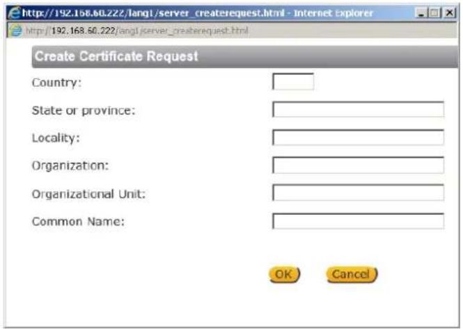
Figure 38: Create Cercate Request Dialog Box
-
Enter the informaon in the appropriate eld. A denion of each of the required elds follows.
-
Country – Enter a two-leer combinaon code to indicate the specific country in which the cercate will be used. For instance, type “US” to indicate United States.
■ State or province – Enter the local administrave region. - Locality – Enter other geographical informaon.
- Organizaon – Enter the name of the organizaon to which the enty idened in Common Name belongs.
- Organizaonal Unit – Enter the name of the organizaonal unit to which the enty idened in the Common Name eld belongs.
-
Common Name – Indicate the name of the person or other entity that the cercate idenes (oen used to identify the website).
-
Click OK to save the details of the cercate request aer compleon. When the request is complete, the subject of the Created Request is displayed in the Subject eld

Figure 39: Created Request Subject
- To view details of the Cercate Request, click PROPERTIES below the Subject eld. The Cercate Request Properes dialog box opens. If you want to remove the cercate, click REMOVE.
| Certificate Request Properties | |
| Certificate Request | |
| Version | 0 |
| Subject | C=US, ST=NJ, L=Ridgefield Park, O=DVTEL LTD., OU=Technical Writing, CN=TW |
| Subject Public Key Info | |
| Public Key Algorithm | RSA Encryption |
| RSA Public Key | |
| Modulus (1024 bit) | dd 16 28 4a 92 17 b0 b6 af 6c 33 09 46 c6 dd 32 6e a4 fc 1f 83 fd b2 b3 b6 b6 5b 4d ff 47 59 30 c4 91 4b 52 b1 f3 10 d0 bd e9 e0 2d 1a e4 db c6 fb 6f 50 e2 97 30 5e a3 7f 98 fc 09 39 fb b2 66 1b 93 fe 75 9c 76 86 49 87 73 57 55 4b 24 4f 5f 07 f0 0b e9 40 d2 40 9d 97 76 25 00 c3 93 7f 98 b1 b7 34 fb a2 4f 53 11 21 38 83 70 ef 1f 0b 2a a3 2a 6a 87 cf b8 00 69 33 88 66 26 fd 34 b0 b5 |
| Exponent | 65537 |
| Attributes | a0:00 |
| Certificate Request (PEM format) | |
----BEGIN CERTIFICATE REQUEST---- MIIBsjCCARsCAQAawcjELMAkGA1UEBhMCVVMxCzAJBgNVBAgMAk5KMRgwFgYDVQQH DA9SaWRnZWZpZWxkIFBhcmsxEzARBgNVBAoMCKRWVEVMIExURC4xGjAYBgNVBAsM EVRJy2huaWNhbCBXcml0aW5nMQswCQYDVQQDDAJVuzCBnzANBgkqhkiG9w0BAQEF AAOBjQAwgYkCgYE3RYoSpIXsLavbDMJRbsdMm6k/B+D/bKztrZbTf9HWTDEkUtS sfMQ0L3p4C0a5NvG+29Q4pcwXqN/mPwJOfuyZhuT/nWcdoZJh3NXVUskT18H8Avp QNJAnZd2JQQDDk3+Ysbc0+6JPUxEhOINw7x8LKqMqaofPuABpM4hmJv00slUCAwEA AaAAMA0GCSqGSIb3DQEBBAUAA4GBAD9y0UiOdDGIYS79T6gr0KWocPwFmSGwgq5T rjpVpEt1jrSKMLIVoa6ue00tyyB6nT2UI8JU3+UjAJwEBLB8P4v5S8vo/tkUn1qy 5LTe1kLxkFEOweqDvBIRFVGaj20a1IcBQQq+bJXdC358t2y/Fjklo9ONU76e79yk mnhYPIxh ----END CERTIFICATE REQUEST----
Figure 40: Cercate Request Properes Dialog Box
- Copy the PEM-formaed request and send it to your CA.

Note:
The self-signed cercate does not provide the same high level of security as a cercate issued by a Cercate Authority (CA).
9.3.2.3 IP Filter
The IP Iter restricts access to the camera by denying/allowing specic IP addresses. Click the IP Iter tab under the category Security in the sidebar to display the following page.

Figure 41: IP Filter Screen
To enable the IP Iter
- Check the box to enable the IP Iter funcon. Once enabled, the listed IP addresses (IPv4) are allowed or denied access to the camera.
- Select Allow or Deny from the drop-down list.
- Click APPLY to determine the IP Iter behavior.
To add or delete an IP address
- Enter the IP address in the Filtered IP Addresses text box.
- Click ADD to add a new Itered address. The Filtered IP Addresses box shows the currently congured IP addresses. Up to 256 IP address entries may be specied.
- To remove an IP address from the list, select the IP address and then click DELETE.
9.3.2.4 IEEE 802.1X
The camera is allowed to access a network protected by 802.1X/EAPOL (Extensible Authencaon Protocol over LAN). Users must contact the network administrator to obtain cercates, user IDs, and passwords.

Figure 42: IEEE 802.1X/EAP-TLS Screen
CA Cercate
The CA cercate is created by the Cercate Authority for the purpose of validang itself. Click Browse to locate the le and UPLOAD to upload the cercate to check the server's identy.
Client Cercate
Upload the Client Cercate to authenticate the camera. Click Browse to locate the le and UPLOAD to upload the cercate.
Private Key
Upload the Private Key to authenticate the camera. Click Browse to locate the le and UPLOAD to upload the private key.
Sengs
- Identity – Enter the user identity (user name) associated with the cercate. Up to 16 characters can be used.
- Private Key Password – Enter the password associated with the user identity. Up to 16 characters can be used.
Enable IEEE 802.1X
Select the checkbox to enable IEEE 802.1X security. Click SAVE to save the IEEE 802.1X/EAPTLS seng.
9.3.3 Network
From the System screen, click the Network tab.
The following screens are available from the Network tab:

9.3.3.1 Basic
The Basic screen is used to congregate the camera's basic network sengs.

Figure 43: Network > Basic Screen
It is possible to connect to the camera with either xed or dynamic (DHCP) IP address. The camera also provides PPPoE (Point-to-Point Protocol over Ethernet) support for users who connect to the network via PPPoE.
The Basic screen is divided into three seconds: General, Advanced and IPv6 Conguraon.
1. General
Select one of the following opons in the General area for conguring network sengs:
- Get IP address automacally
■ Use xed IP address
■ User PPoE
- Get IP address automacally
If you select Get IP address automacally, you can use the DNA ulity, which is provided in the supplied CD, to obtain the IP address from a DHCP server on the network. See Using the DNA Ulity to Search and Access the Camera.

Note:
For future reference, record the camera's MAC address, which is found on the camera label.
- Use xed IP address
The camera's default seng is Use xed IP address. Refer to Using the DNA Ulity to Search and Access the Camera for login with the default IP address. You may use DNA or enter the IP address in your Internet browser's URL address bar.
To set up a new stac IP address
- Select the Use xed IP address opon.
-
Enter the following informaon:
-
IP address – The IP address is necessary for network idencaon.
- Subnet mask – Used to determine if the desnaon is in the same subnet. The default value is 255.255.255.0.
- Default gateway – Used to forward frames to desnaons in a dierent subnet. An invalid gateway seng causes transmission to desnaons in other subnets to fail.
- Primary DNS – The primary domain name server that translates host names into IP addresses.
- Secondary DNS – A secondary domain name server that backs up the primary DNS.
- Use PPPoE
To use PPPoE
- Enter your PPPoE user name and password into the respective elds.
- Click SAVE to conrm the sengs.
2. Advanced
Enter the following advanced parameters in the Advanced secon of the screen:
- Web Server port – The default web server port is 80. Once the port is changed, the user must be need the change for the conneccon to be successful. For instance, when the Administrator changes the HTTP port of the camera whose IP address is 192.168.0.100 from 80 to 8080, the user must type in the web browser hp://192.168.0.100:8080 instead of hp://192.168.0.100.
- RTSP port – The default seng of the RTSP port is 554. The range is from 1024 to 65535.
- MJPEG over HTTP port – The default seng of MJPEG over HTTP port is 8008. The range is from 1024 to 65535.
- HTTPS port – The default seng of HTTPS port is 443. The range is from 1024 to 65535.
- MTU – The MTU (Maximum Transmission Unit) is the greatest amount of data that can be transferred in one physical frame on the network. For Ethernet, the MTU is 1500 bytes (default seng). For PPPoE, the MTU is 1492. The range is from 700 to 1500 bytes.

Note: Be sure to assign a dierent port number for each service menoned above.
Click SAVE to save the sengs.
3. IPv6 Address Conguraon
IPv6 is not supported.
9.3.3.2 QoS
QoS (Quality of Service) provides dierenated service levels for dierent types of trac packets and guarantees delivery of priority services during periods of network congeson. Adapng the Dierenated Services (DiffServ) model, trac ows are classified and marked with DSCP (DiServ Code point) values, and as a result receive the corresponding forwarding treatment from DiServ-capable routers. DSCP conguraon sengs are entered in the System > Network > QOS screen:

Figure 44: QoS Screen
DSCP Sengs
The DSCP value range is from 0 to 63. The default DSCP value is 0 (DSCP disabled). The camera uses the following QoS classes: Video, Audio, and Management.
- Video DSCP – This class consists of applicants such as MJPEG over HTTP, RTP/RTSP and RTSP/HTTP.
■ Audio DSCP – The camera supports audio.
■ Management DSCP – This class consists of HTTP trac (web browsing).
Click SAVE when complete.

Note: To enable this funcon, make sure the switches/routers in the network support QoS.
9.3.3.3 SNMP Sengs
The Simple Network Management Protocol (SNMP) enables the camera to be monitored and managed remotely by the network management system. SNMP conguraon sengs are entered in the System > Network > SNMP screen.
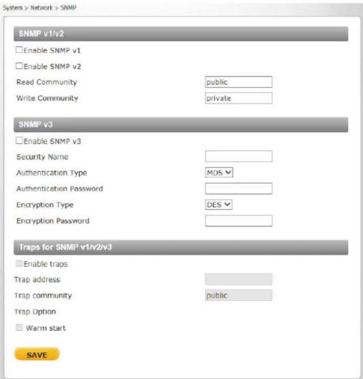
Figure 45: SNMP Sengs Screen
SNMP v1/v2
- Enable SNMP v1 or Enable SNMP v2 – Select the version of SNMP (v1 or v2) to use by checking the relevant box.
- Read Community – Specify the community name that has read-only access to all supported SNMP objects. The default value is public.
Write Community – Specify the community name that has read/write access to all supported SNMP objects (except read-only objects). The default value is private.
SNMP v3
SNMP v3 provides important security features including:
- Condenality – Encrypon of packets to prevent snooping by an unauthorized source.
- Integrity – Message integrity to ensure that a packet has not been tampered with in transit including an oponal packet replay protecon mechanism.
- Authencaon – To verify that the message is from a valid source.
To enable the SNMP v3 protocol, enter the appropriate data and passwords requested:
■ Enable SNMP v3 – Select the checkbox.
■ Security Name – See note below.
- Authencaon Type – Select MD5 or SHA from the drop-down list. See note below.
- Authencaon Password – See note below.
- Encrypon Type – Select DES or AES from the drop-down list. See note below.
■ Encrypon Password – See note below.

Note:
You may have to consult with your System Administrator to acvate this funcon.
Traps for SNMP v1/v2/v3
Traps are used by the camera to send messages to a management system for important events or status changes.
■ Enable traps – Check this box to acvate trap reporg.
- Trap address – Enter the IP address of the management server.
- Trap community – Enter the community to use when sending a trap message to the management system. The default value is public.
- Trap Opon
- Warm start – A warm start SNMP trap signies that the SNMP device, such as the camera, performs a soware reload.
Click SAVE when complete.
9.3.3.4 UPnP
The System > Network > UPnP screen enables the Universal Plug-and-Play protocol on your network devices.

Figure 46: UPnP Screen
UPnP Sengs
- Enable UPnP – If UPnP is enabled and a camera is discovered on the LAN, the icon of the connected camera appears in My Network Places, allowing direct access, as seen below.
![Network Organize Search Active Directory Network and Sharing Center Add a printer Add a wireless device Favorites Desktop Downloads Recent Files Libraries Documents Music Pictures Videos Computer Local Disk (C:) Documents (E:) Ironics (J:) composites Engineering Services (C:) (1) [192.108.50.6] (V) Store (C:) Network * Media Devices (Z): WS2-EXCHELMAN WS-ETHOPSON Admins * Other Devices (Y): CF-5212-00 CF-6208-00 CF4-6221-00 CF4-6208-13-1 NA000 9 items](/content/2026/05/980486/images/52fde2b54bbb00d6f72a52ade2fcf5244b0e60e7e74cbed59f9e5ce6d361798b.jpg)
Figure 47: Direct Access to Camera with UPnP Enabled

Note:
To enable this funcon, make sure the UPnP component is installed on your computer. Refer to Install UPnP Components for the Windows 7, Windows 8, and Windows 8.1 procedure.
- Enable UPnP port forwarding – When UPnP port forwarding is enabled, the camera is allowed to open the web server port on the router automacally.

Note:
To enable this funcon, make sure that your router supports UPnP and that it is acvated.
- Friendly name – Enter the name for the camera for idencaon.
Click SAVE to save the sengs.
9.3.3.5 DDNS
Dynamic Domain Name System (DDNS) allows a host name to be constantly synchronized with a dynamic IP address. This permits those using a dynamic IP address to be accessed by a stac domain name. DDNS conguraon sengs are entered in the System > Network > DDNS screen:

Figure 48: DDNS Screen
To use DDNS
- Select the Enable DDNS checkbox.
- From the Provider drop-down list, select a DDNS host provider name.
- In the Host name text box, enter the registered domain name.
- In the Username/E-mail text box, enter the username or e-mail address required by the DDNS provider for authencaon.
- In the Password/Key text box, enter the password or key required by the DDNS provider for authencaon.
Click SAVE to save the seng.
9.3.3.6 Mail
Simple Mail Transfer Protocol (SMTP) is a protocol for sending e-mail messages between servers. It is a relatively simple, text-based protocol, where a text message is transferred to one or more specied recipients. The Administrator can send an e-mail via Simple Mail Transfer Protocol (SMTP) when an alarm is triggered. E-mail nocaons are set by selecng the checkbox for an e-mail-related triggered acon on the IO, Network Failure Detecon, Tampering, Periodic Event, Manual trigger, and Moon Detecon screens.
SMTP (E-mail) server conguraon sengs are entered in the System > Network > Mail screen:

Figure 49: Mail Screen – SMTP
Two SMTP server accounts can be congured with or without SSL encrypon. Enter the sengs for the 1 st SMTP server and 2 nd SMTP server in the appropriate elds. Sengs include SMTP server, server port (the default port is 25), account name, password, and recipient e-mail address sengs. To encrypt e-mail with SSL, select the 1 st SMTP SSL and/or 2 nd SMTP SSL checkbox. For SMTP server details, contact your network service provider. Click SAVE when nished.
9.3.3.7 FTP
The Administrator can send an alarm message to one or two File Transfer Protocol (FTP) sites when moon is detected. FTP nocaons are set by selecng the checkbox for an FTP-related triggered
acon on the IO, Network Failure Detecon, Tampering, Periodic Event, Manual trigger, and Moon Detecon screens.
For each server, enter the server IP address, server port number, user name, password, and remote folder path. Sengs are entered in the System > Network > FTP screen:
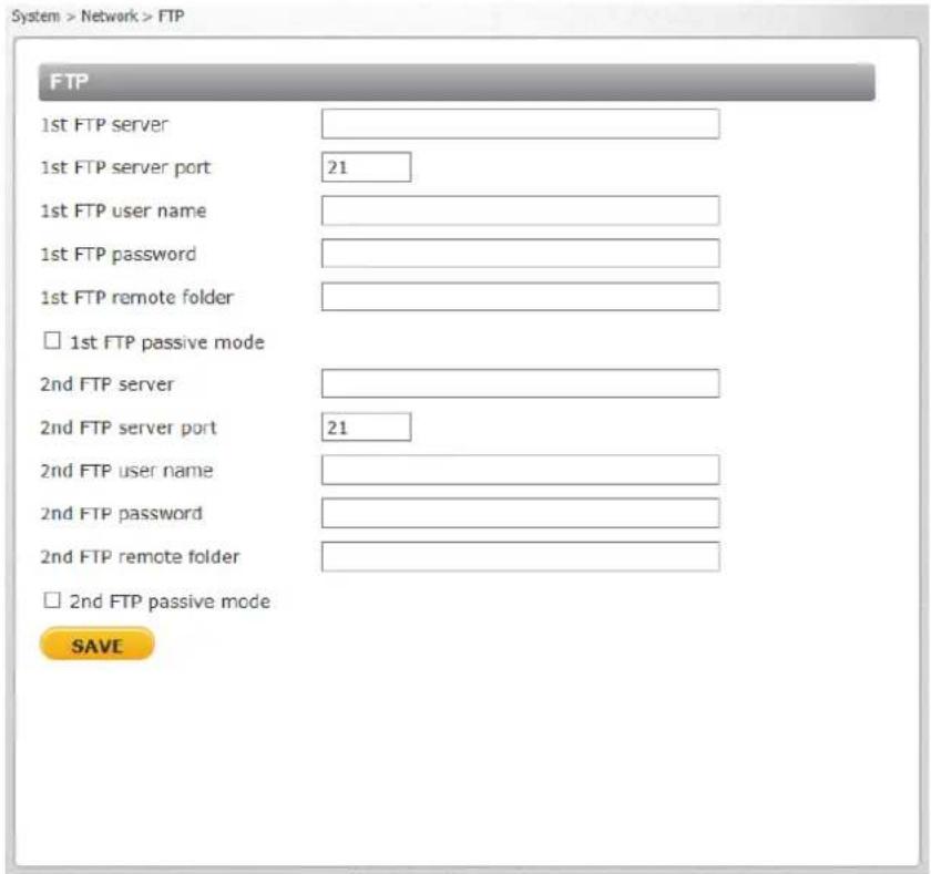
Figure 50: FTP Screen
To use passive mode, select the 1st FTP passive mode or 2nd FTP passive mode checkbox for the respective server. In passive mode, FTP the client initiates both connexons to the server, solving the problem of rewalls iterating the incoming data port connexon to the client from the server.
In order to support passive mode FTP on the server-side rewall, the following communicaon channels must be opened:
- FTP server's port 21 from anywhere (client initiates conncon)
- FTP server's port 21 to ports > 1023 (server responds to client's control port)
- FTP server's ports > 1023 from anywhere (client initiates data conneccon to random port specied by server)
- FTP server's ports > 1023 to remote ports > 1023 (server sends ACKs and data to client's data port)
Click SAVE when nished.
9.3.3.8 HTTP
An HTTP nocaon server detects nocaon messages of triggered events sent from cameras. HTTP nocaons are set by selecng the Send HTTP nocaon checkbox on the IO, Tampering, Manual trigger, and Moon Detecon screens.
Two nocoon server accounts (Alarm Triggered and Moon Detecon) can be set up and sent to the specied HTTP servers. For each server, enter the HTTP details, including server IP address, user name, and password. Sengs are entered in the System > Network > HTTP screen:

Figure 51: HTTP Screen
Click SAVE when nished.
9.3.4 Events Setup
The Events Setup tab includes the following screens:
• 10
• Network Failure Detecon
- Tampering
• Day/Night Trigger
- Periodic Event
- Manual Trigger
9.3.4.1 IO
The IO screen is used to control input and output alarms and messages, which are generated when an event is recognized by the system.

Figure 52: IO Screen
The Administrator can select from the following opons:
■ Select O to disable an alarm.
■ Select On to enable an alarm (default seng).
- Select By Schedule to set a schedule. Then click Please Select to select up to 10 schedules from the drop-down list that opens. The selected schedules are displayed in the Please Select text box. To set a schedule, open the Schedule tab.
Click SAVE aer conguring the sengs.
Select an alarm type (Normal close or Normal open) that corresponds to the alarm applicaon. Normal open is the default seng. Click SAVE aer conguring the sengs.
9.3.4.1.3 Alarm Output
Dene the normal alarm output signal as Output high or Output low, according to the current alarm applicaon. Output high is the default seng. Click SAVE aer conguring the sengs.
The Administrator can specify various alarm acons to take when an alarm is triggered. The following opons are available:
- Enable alarm output – Select this checkbox to enable alarm relay output (default seng).
- Send message by FTP – Select the checkbox send an alarm message by FTP when an alarm is triggered.
- Upload image by FTP – Select this box to assign an FTP site and congure the parameters shown. When an alarm is triggered, event images are uploaded to the designated FTP site.

Note:
Images can be sent by FTP only when MJPEG is selected as the video stream from the Video Format screen.
Follow these steps:
- From the FTP address drop-down list, select one of the two FTP addresses to use.
- From the Pre-trigger buer and Post-trigger buer drop-down lists, select the number of frames for the buer from 1-20 frames.

Figure 53: Upload Image by FTP
- Select the Connue image upload checkbox to upload an image by FTP for a dened period of me or while the trigger is acute. Select one of the following opons:
- To specify the length of me for the upload, select Upload for and enter the number of seconds in the text box.
• To upload while the trigger is acve, select Upload while the trigger is acve.
In the Image Frequency text box, from the drop-down list select the number of frames per seconds from 1-15 for the upload.

Note:
Make sure that FTP conguraon has been completed. See FTP for details.
- Send HTTP nocaoon – Select this checkbox to send a nocaoon by HTTP. Select the desnaon HTTP address from the drop-down menu and specify the parameters for event
nocaons by the IO event triggered. When an alarm is triggered, the nocaon will be sent to one of two specied HTTP servers. See gure below.

Figure 54: Send HTTP Nocaon
- Record video clip – Select this box in order to save the alarm-triggered recording to your microSDXC card or to the NAS. Enter the number of seconds for the pre-trigger buer. Select the rst radial buon if you wish to upload for a specied length of me and enter the number of seconds. Alternatively, select the second radial buon to upload during the acve trigger.

Figure 55: Record Video Clip

Note:
In order to use this funcon, make sure that local recording with a microSDXC card is acvated and that the NAS is properly congured. See Recording for further details.
- Send message by E-Mail – Select the checkbox send an alarm message by e-mail when an alarm is triggered. The e-mail address is entered in the Mail screen.
- Upload image by E-Mail – Select this checkbox to assign an e-mail address for sending the image captured by a triggered alarm. The e-mail address is entered in the Mail screen.

Note:
Images can be sent by e-mail only when MJPEG is selected as the video stream from the Video Format screen.
- From the E-Mail address drop-down list, select one of the two e-mail addresses.
- From the Pre-trigger buer and Post-trigger buer drop-down lists, select the number of frames for the buer from 1-20 frames.
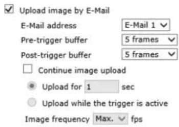
Figure 56: Upload Image by E-Mail
- Check the Connue image upload box if you wish to upload an image by e-mail for a dened period of me or while the trigger is acute. Select one of the following opons:
- To specify the length of me for the upload, select Upload for and enter the number of seconds in the text box.
• To upload while the trigger is acve, select Upload while the trigger is acve.
In the Image Frequency text box, from the drop-down list select the number of frames per seconds from 1-15 for the upload.

Note:
Make sure that SMTP conguraon has been completed. See Mail for details.
Click SAVE aer conguring the sengs.
9.3.4.1.5 File Name
- File Name – Enter a le name in the eld, for example image.jpg. The uploaded image's le name format is set in this secon. Select one that meets your requirements.
■ Add date/me sux (default seng)
File name: imageYYMMDD_HHNNSS_XX.jpg
Y: Year, M: Month, D: Day
H: Hour, N: Minute, S: Second
X: Sequence Number
■ Add sequence number sux (no maximum value)
File name: imageXXXXXXXX.jpg
X: Sequence Number
■ Add sequence number sux (limited value)
File Name: imageXX.jpg
X: Sequence Number
The le name sux ends at the number being set. For example, if the seng is up to “10,” the le name will start from 00, end at 10, and then start over again.
■ Overwrite
The original image in the FTP site will be overwritten by the new uploaded le with a static lename.
Click SAVE aer conguring the sengs.
9.3.4.2 Network Failure Detecon
Sengs on the Network Failure Detection screen enable the camera to periodically ping another IP device within the network to detect a network failure, for example, if a video server is disconnected. By implementing local recording through a microSDXC card, the camera can operate as a backup recording device for the surveillance system if network communicaon is lost due to a network failure.

Figure 57: Network Failure Detecon Screen
The Administrator can select from the following opons:
■ Select O to disable an alarm (default seng).
- Select On to enable an alarm.
- Select By Schedule to set a schedule. Then click Please Select to select up to 10 schedules from the drop-down list that opens. The selected schedules are displayed in the Please Select text box. To set a schedule, open the Schedule tab.
Click SAVE aer conguring the sengs.
9.3.4.2.2 Detecon Type
In the text box, enter the IP address to ping and the me interval (in minutes) between pings. Click SAVE aer conguring the sengs.
9.3.4.2.3 Triggered Acon
The Administrator can specify various alarm acons to be taken when an alarm is triggered. The opons are listed below.
- Enable alarm output – Check this box and select the predened type of alarm output (low or high) to enable alarm relay when a network failure is detected.
- Send message by FTP – Select whether to send an alarm message by FTP when a network failure is detected.
- Record video clip – Select this box in order to save the alarm-triggered recording into a microSDXC card or the NAS. Enter the number of seconds for the pre-trigger buer. Select the rst radial buon to upload for a specied length of me and enter the number of seconds. Alternatively, select the second radial buon to upload during the acve trigger. See Figure 55: Record Video Clip.

Note: In order for this funcon to be implemented, make sure that local recording with a microSDXC card is acvated and that the NAS is properly congured. See Recording for further details.
- Send message by E-Mail – Select whether to send an alarm message by e-mail when a network failure is detected.
Click SAVE to save the network failure detecon sengs.
9.3.4.3 Tampering
The Tampering screen enables the camera to deal with tampering (such as deliberate redirecon, blocking, paint-spraying, and obscuring the lens, etc.). Using video analysis, the camera can react to such events by sending nocaons or uploading snapshots to the specied desnaon(s).
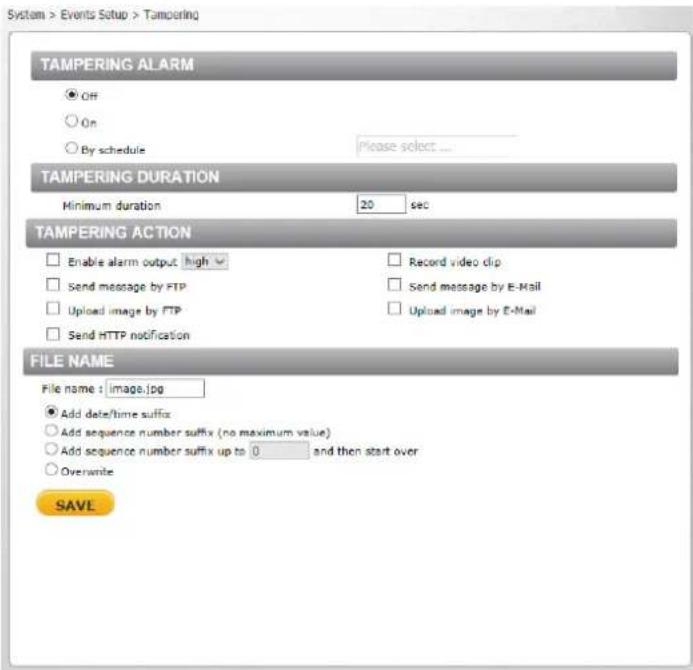
Figure 58: Tampering Screen
Detecon of camera tampering is achieved by measuring the dierences between the older frames of video (which are stored in buers) and more recent frames.
9.3.4.3.1 Tampering Alarm
The Administrator can select from the following opons:
■ Select O to disable the tampering alarm (default seng).
■ Select On to enable the tampering alarm.
- Select By Schedule to set a schedule. Then click Please Select to select up to 10 schedules from the drop-down list that opens. The selected schedules are displayed in the Please Select text box. To set a schedule, open the Schedule tab.
Click SAVE aer conguring the sengs.
9.3.4.3.2 Tampering Duraon
Minimum tampering duraon is the me for video analysis to determine whether camera tampering has occurred. Minimum duraon can also be interpreted as dening the tampering threshold; a longer duraon represents a higher threshold.
In the Minimum duraon text box, enter the tampering duraon me in seconds. The range is from 10 to 3600 seconds.
9.3.4.3.3 Tampering Acon
The Administrator can specify mulple alarm acons to be taken when tampering is detected. The opons are listed as follows:
- Enable alarm output – Check this box and select the predened type of alarm output (high or low) to enable alarm relay when tampering is detected.
- Send Message by FTP – The Administrator can select whether to send an alarm message by FTP when tampering is detected.
- Upload Image by FTP – Selecting this open enables you to assign an FTP site and congregate various parameters, as seen in Figure 53: Upload Image by FTP. When tampering is detected, event images will be uploaded to the designated FTP site.

Note: Images can be sent by FTP only when MJPEG is selected as the video stream from the Video Format screen.
Specify the FTP address to use from the drop-down menu. Select the number of frames for the pre-trigger and post-trigger buers from the drop-down menu of 1-20 frames.
Check the box for Connue image upload if you wish to use this opon. To specify the length of me for the upload, click this radial buon and enter the number of seconds. To upload while the trigger is acve, click this radial buon.
Finally, select the number of frames per second from the drop-down menu next to Image frequency.
- Send HTTP nocaon – Check this opon, select the desnaon HTTP address, and specify the parameters for HTTP nocaons. When the tampering alarm is triggered, the HTTP nocaons can be sent to the specied HTTP server. See Figure 54: Send HTTP Nocaon.
- Record video clip – Select this box in order to save the alarm-triggered recording into a microSDXC card. Enter the number of seconds for the pre-trigger buer. Select the rst radial buon to upload for a specied length of me and enter the number of seconds. Alternatively, select the second radial buon to upload during the acve trigger. See Figure 55: Record Video Clip.

Note:
In order for this funcon to be implemented, make sure that local recording with a microSDXC card is acvated and that the NAS is properly congured. See Recording for further details.
- Send message by E-Mail – The Administrator can select whether to send an alarm message by e-mail when tampering is detected.
- Upload Image by E-Mail – Selecting this open enables you to assign an e-mail address and congregate various parameters, as shown in Figure 56: Upload Image by E-Mail. When tampering is detected, event images will be sent to the designated e-mail address.

Note:
Images can be sent by e-mail only when MJPEG is selected as the video stream from the Video Format screen.
Select one of two e-mail addresses from the drop-down menu. Select the number of frames for the pre-trigger and post-trigger buers from the drop-down menu of 1-20 frames.
Check the box for Connue image upload if you wish to use this opon. To specify the length of me for the upload, click this radial buon and enter the number of seconds. To upload while the trigger is acve, click this radial buon. Finally, select the number of frames per second from the drop-down menu next to Image frequency.

Note:
Make sure SMTP or FTP conguraon has been completed. See the Mail and FTP seconds for further details.
9.3.4.3.4 File Name
- File Name – Enter a le name in the eld, for example image.jpg. The uploaded image's le name format is set in this secon. Select one that meets your requirements.
- Add date/me sux (default seng) File name: imageYYMMDD_HHNNSS_XX.jpg Y: Year, M: Month, D: Day H: Hour, N: Minute, S: Second X: Sequence Number
- Add sequence number sux (no maximum value) File name: imageXXXXXXX.jpg X: Sequence Number
- Add sequence number sux (limited value) File Name: imageXX.jpg X: Sequence Number
The le name sux ends at the number being set. For example, if the seng is up to “10,” the le name will start from 00, end at 10, and then start over again.
■ Overwrite
The original image in the FTP site will be overwritten by the new uploaded le with a static filename.
Click SAVE aer conguring the sengs.
9.3.4.4 Day/Night Trigger
The Day/Night Trigger screen is used to enable the camera to trigger a device connected to the camera's alarm output when the camera switches to Day or Night mode, which is set on the IR Funcon screen.

Figure 59: Day/Night Trigger Screen
In the Day/Night Trigger secon, select On to enable the Day/Night Trigger or O to disable it.
In the Day/Night Type secon, select Day when the camera enters Day mode, for example to deacvate an external device, such as a lightng source. Select Night to acvate an external device when the camera enters Night mode.
In the Triggered Acon secon, check Enable alarm output to acvate an external lightng source.
Depending on the voltage requirements of the external device, from the drop-down menu select high or low.
9.3.4.5 Periodic Event
The Periodic Event screen is used to specify an alarm to be triggered at a specified me interval.
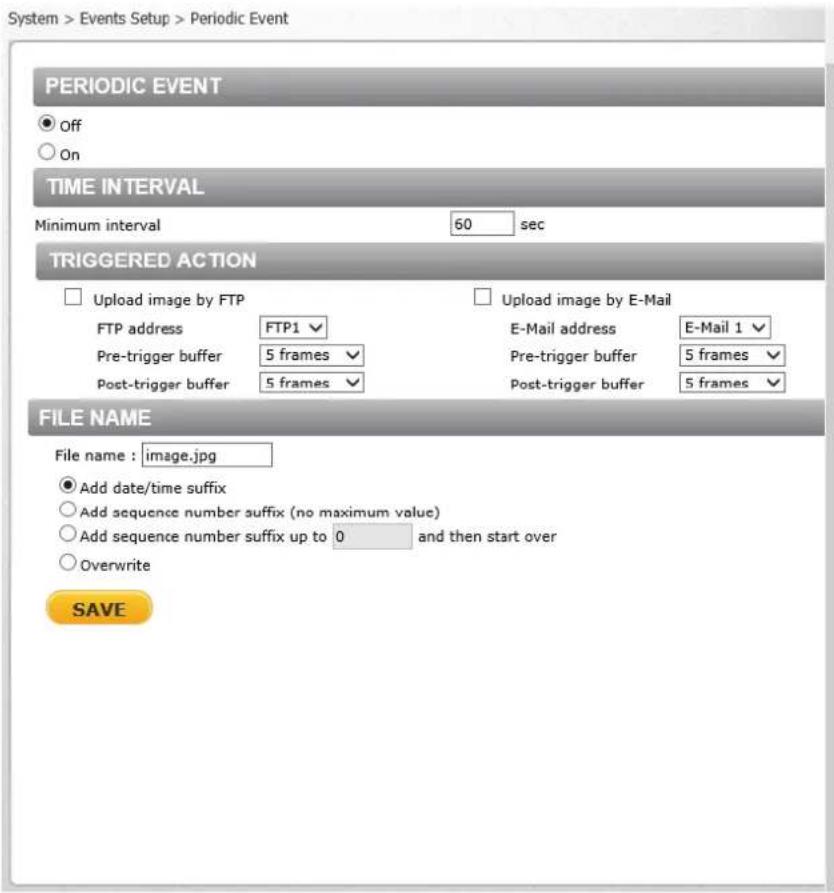
Figure 60: Periodic Event Screen
9.3.4.5.1 Periodic Event
Select O or On to acvate this funcon. The default is O.
9.3.4.5.2 Time Interval
In the Minimum interval text box, enter the number of seconds for the minimum interval between alarms. The range is from 20 to 3600 seconds.
9.3.4.5.3 Triggered Acon
The Administrator can specify mulple alarm acons to be taken when a triggering event occurs. The opons are listed as follows:
- Upload Image by FTP – Selecting this open enables you to assign an FTP site and congregate various parameters, as seen in Figure 53: Upload Image by FTP. When the alarm is triggered, event images will be uploaded to the designated FTP site.

Note:
Images can be sent by FTP only when MJPEG is selected as the video stream from the Video Format screen.
- Specify the FTP address to use from the drop-down menu. Select the number of frames for the pre-trigger and post-trigger buers from the drop-down menu of 1-20 frames.
- Upload Image by E-Mail – Selecting this open enables you to assign an e-mail address and congregate various parameters, as shown in Figure 56: Upload Image by E-Mail. When an alarm is triggered, event images will be sent to the designated e-mail address.

Note:
Images can be sent by e-mail only when MJPEG is selected as the video stream from the Video Format screen.
Select one of two e-mail addresses from the drop-down menu. Select the number of frames for the pre-trigger and post-trigger buers from the drop-down menu of 1-20 frames.

Note:
Make sure SMTP or FTP conguraon has been completed. See the Mail and FTP seconds for further details.
9.3.4.5.4 File Name
- File Name – Enter a le name in the eld, for example image.jpg. The uploaded image's le name format is set in this secon. Select one that meets your requirements.
- Add date/me sux (default seng) File name: imageYYMMDD_HHNNSS_XX.jpg Y: Year, M: Month, D: Day H: Hour, N: Minute, S: Second X: Sequence Number
- Add sequence number sux (no maximum value) File name: imageXXXXXXX.jpg X: Sequence Number
- Add sequence number sux (limited value) File Name: imageXX.jpg X: Sequence Number
The le name sux ends at the number being set. For example, if the seng is up to “10,” the le name will start from 00, end at 10, and then start over again.
■ Overwrite
The original image in the FTP site will be overwritten by the new uploaded le with a static lename.
Click SAVE aer conguring the sengs.
9.3.4.6 Manual Trigger
The Manual Trigger screen is used to specify an alarm to be manually triggered. You can denote acon to take when an alarm occurs from the System > Events Setup > IO screen.
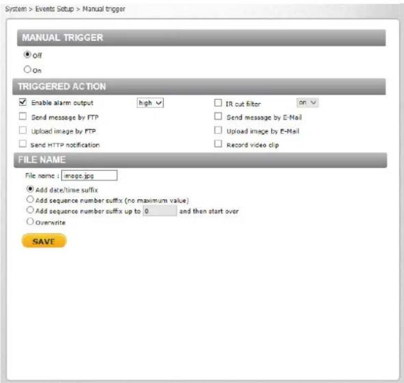
Figure 61: Manual Trigger Screen
9.3.4.6.1 Manual Trigger
Select O or On to acvate this funcon. The default is O.
9.3.4.6.2 Triggered Acon
Specify one or both alarms to trigger:
- Enable alarm output – Check this box and select the predened type of alarm output (high or low) to enable alarm relay when an alarm is triggered.
- Send Message by FTP – The Administrator can select whether to send an alarm message by FTP when an alarm is triggered.
- Upload Image by FTP – Selecting this opon enables you to assign an FTP site and congregate various parameters, as seen in Figure 53: Upload Image by FTP. When an alarm is triggered, event images will be uploaded to the designated FTP site.

Note:
Images can be sent by FTP only when MJPEG is selected as the video stream from the Video Format screen.
Specify the FTP address to use from the drop-down menu. Select the number of frames for the pre-trigger and post-trigger buers from the drop-down menu of 1-20 frames.
Check the box for Connue image upload if you wish to use this opon. To specify the length of me for the upload, click this radial buon and enter the number of seconds. To upload while the trigger is acve, click this radial buon.
Finally, select the number of frames per second from the drop-down menu next to Image frequency.
- Send HTTP nocaoon – Check this opon, select the desnaon HTTP address, and specify the parameters for HTTP nocaoons. When an alarm is triggered, the HTTP nocaoons can be sent to the specied HTTP server. See Figure 54: Send HTTP Nocaoon.
- IR Cut Filter – Select this checkbox to trigger an event when the IR cut Iter is acvated. From the drop-down menu, select on or o. When the IR Cut Iter is set to on, the IR LED illuminator is acvated for use in low-light environments in which Night mode is normally used.
- Send message by E-Mail – The Administrator can select whether to send an alarm message by e-mail when an alarm is triggered.
- Upload Image by E-Mail – Selecting this open enables you to assign an e-mail address and congregate various parameters, as shown in Figure 56: Upload Image by E-Mail. When an alarm is triggered, event images will be sent to the designated e-mail address.

Note:
Images can be sent by e-mail only when MJPEG is selected as the video stream from the Video Format screen.
Select one of two e-mail addresses from the drop-down menu. Select the number of frames for the pre-trigger and post-trigger buers from the drop-down menu of 1-20 frames.
Check the box for Connue image upload if you wish to use this opon. To specify the length of me for the upload, click this radial buon and enter the number of seconds. To upload during the acve trigger, click this radial buon. Finally, select the number of frames per second from the drop-down menu next to Image frequency.

Note:
Make sure SMTP or FTP conguraon has been completed. See the Mail and FTP seconds for further details.
- Record video clip – Select this box in order to save the alarm-triggered recording into a microSDXC card. Enter the number of seconds for the pre-trigger buer. Select the rst radial buon to upload for a specied length of me and enter the number of seconds. Alternatively, select the second radial buon to upload during the acve trigger. See Figure 55: Record Video Clip.

Note:
To implement funcon, make sure that local recording with a microSDXC card is acvated and that the NAS is properly congured. See Recording for details.
9.3.4.6.3 File Name
- File Name – Enter a le name in the eld, for example image.jpg. The uploaded image's le name format is set in this secon. Select one that meets your requirements.
- Add date/me sux (default seng) File name: imageYYMMDD_HHNNSS_XX.jpg Y: Year, M: Month, D: Day H: Hour, N: Minute, S: Second X: Sequence Number
- Add sequence number sux (no maximum value)
File name: imageXXXXXXXX.jpg
X: Sequence Number
■ Add sequence number sux (limited value)
File Name: imageXX.jpg
X: Sequence Number
The le name sux ends at the number being set. For example, if the seng is up to "10," the le name will start from 00, end at 10, and then start over again.
■ Overwrite
The original image in the FTP site will be overwritten by the new uploaded le with a static lename.
Click SAVE aer conguring the sengs
From the Edge Recording tab it is possible to congregate the following screens:
- SD Card
• Network Share
- Recording
9.3.5.1 SD Card
You can locally record up to 128GB on a Class 10 microSDXC card. The SD Card page shows the capacity informaon of the memory card and a recording list of all the recording les saved on the card. You can also format the card and implement automatc recording cleanup on this page. To implement microSDXC card recording, see Recording.
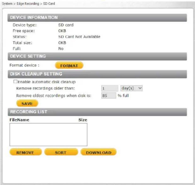
Figure 62: SD Card Screen

Note:
Format the microSDXC card when using it for the rst me. Formang is also required when a memory card has been used on one camera and is then transferred to a camera that uses a dierent soware plaorm.
Device Informaon
Upon inserng the microSDXC card, card informaon, such as the memory capacity and status, is displayed.
Device Seng
Click Format to format the memory card.
Disk Cleanup Seng
Enable automac recording cleanup by selecng Enable automac disk cleanup. From the pull-down menu, specify the minimum length of me over which to remove recordings. For example, remove recordings over 10 days old. Enter the percent of disk capacity used in order to remove the oldest recordings. Click SAVE when nished.
Recording List
Each video le on the microSDXC card is listed in the Recording List table below. The maximum le size is 60 MB per le. See Recording for further details.
When the recording mode in the Recording screen is set as Always (consecuve recording) and the microSDXC card recording is enabled by events triggered, the system immediately saves a recorded event on the memory card once an event occurs. The camera then returns to the regular recording mode aer events recording.

Figure 63: Video File Recording List
- Remove – To remove a le, rst select the le and then click REMOVE.
- Sort – Click SORT to list the les in the Recording List table in order of name and date.

Note:
The capital leers: R, N, A, (A0), M, (M0) followed by an underscore, appear at the beginning of the le name. They denote the type of recording.
• R - Regular (always or schedule)
• N - Network failure
• M - Moon, (M0 refers to the rst moon window trigger)
- A - Alarm (A0 refers to the rst alarm trigger input).
- Download – To open/download a video clip, rst select the le and then click DOWNLOAD. The selected le window pops up as shown below. Click the AVI le to play the video in the player or download it to a specied locaon.
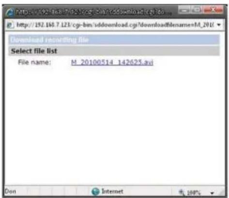
Figure 64: Selected File Window
9.3.5.2 Network Share
The Network Share screen shows the capacity informaon of the Network Aached Storage (NAS) disk and provides a list of all the recording les saved on the disk.

Figure 65: Network Share Screen
You can also format the disk and implement automac recording cleanup on this page. To implement NAS recording, see Recording.
Device Informaon
Upon connecng to the NAS, the following informaon about the disk is displayed:
■ Device type – Displays Network Share
■ Free space – Displays the amount of available storage space in GB
■ Total size – Displays the total amount of storage space in GB
■ Status – Indicates if the camera is online or oine
■ Full – Indicates if the disk is full (Yes/No)
- Protocol – Displays the protocol used by the NAS. The default is SAMBA.
Enter the details for the following elds:
■ Host – Enter the host IP address
- Share – Enter the path for a shared network storage device
- User name – Enter the name of the user accessing the NAS
- Password – Enter the password of the user accessing the NAS
Storage Tools
Click FORMAT to format the NAS.
Disk Cleanup Seng
Enable automac recording cleanup by selecng Enable automac disk cleanup. From the pull-down menu, specify the minimum length of me over which to remove recordings. For example, remove recordings over 10 days old. Enter the percent of disk capacity used in order to remove the oldest recordings. Click SAVE when nished.
Recording List
Each video le stored on the NAS is listed in the Recording list. See Recording for further details. When the recording mode in the Recording screen is set as Always (consecuve recording) and the NAS recording is enabled by events triggered, the system immediately saves a recorded event on the network disk once an event occurs. Then the camera will return to the regular recording mode aer events recording.

Figure 66: Video File Recording List
- Remove – To remove a le, rst select the le and then click REMOVE.
- Sort – Click SORT to list the les in the Recording list in order of name and date.

Note:
The capital leers: R, N, A, (A0), M, (M0) followed by an underscore, appear at the beginning of the le name. They denote the type of recording.
• R - Regular (always or schedule)
• N - Network failure
• M - Moon, (M0 refers to the rst moon window trigger)
- A - Alarm (A0 refers to the rst alarm trigger input).
- Download – To open/download a video clip, rst select the le and then click DOWNLOAD. The selected le window pops up as shown below. Click the AVI le to play the video in the player or download it to a specied locaon.

Figure 67: Selected File Window
9.3.5.3 Recording
The Recording screen is used to select a device and to set a schedule for recording clips. Up to 10 schedules can be set.
In the Recording Storage secon, select the recording device: SD Card or Network Share.

Note:
It is not recommend to record with the microSD card for 24/7 connuously, as it may not be able to support long term connuous data read/write. Contact the manufacturer of the microSD card for informaon regarding its reliability and life expectancy.
In the Recording Schedule secon, specify the recording schedule. Select one of three opons:
■ Disable – Disable this funcon
■ Always – Always use this funcon
■ Only during me frame – Records only during a specied me frame

Figure 68: Recording Screen
To set the recording schedule
- Selecng the day.
- Set the start me.
-
Set the duraon for recording.
-
Click SAVE to conrm the schedule. The schedule is displayed in the table.

Note:
This opon works only if (a) the microSDXC card is installed in the camera or (b) the NAS is congured properly.
9.3.6 Moon Detecon
The moon detecon funcon detects suspicious moon and triggers alarms when moon volume in the detected area reaches or exceeds the determined sensitivity threshold value.
![System > Motion Detection Motion Detection 1 ● off ○ On ○ By schedule Please select ... MOTION DETECTION SETTING Sampling pixel interval [1-10] 1 Detection level [1-100] 10 Sensitivity level [1-100] 80 Time interval(sec) [0-7200] 10 TRIGGERED ACTION □ Enable alarm output high □ Record video clip □ Send alarm message by FTP □ Send alarm message by E-mail □ Upload image by FTP □ Upload image by E-Mail □ Send HTTP notification FILE NAME : image.jpg ● Add date/time suffix ○ Add sequence number suffix (no maximum value) ○ Add sequence number suffix up to 0 and then start over ○ Overwrite SAVE](/content/2026/05/980486/images/f3dd7987a46e0ae4bf87378d805602e8ad7aba6e349e5a3bc2765ee427725cc4.jpg)
Figure 69: Moon Detecon Screen
Within the Live View pane on the Moon Detecon screen, there is a frame (Moon Detecon window) which is used for dening the moon detecon area. To change the size of the Moon Detecon window, move the mouse cursor to the edge of the frame and drag it outward or inward. Moving the mouse to the center of the frame shis the frame to the intended locaon.
Moon Detecon Acvaon
It is possible to dene up to four moon detecon zones within the Moon Detecon window by selecng a number from the drop-down menu.
The moon detecon funcon may be turned on or o in the Moon Detecon secon of the screen. The default seng is O. Alternatively, you may select By schedule to set a schedule.
To set a schedule
- Select By schedule. The message Please Select is displayed.
- Click Please select. A drop-down menu opens.
- From the drop-down menu, select a schedule from 1 to 10. The selected schedules are displayed in a horizontal eld above the drop-down menu.
For instrucons how to set a schedule for moon detecon, refer to Schedule. Below is a screen showing the Schedule drop-down menu with selected schedules.
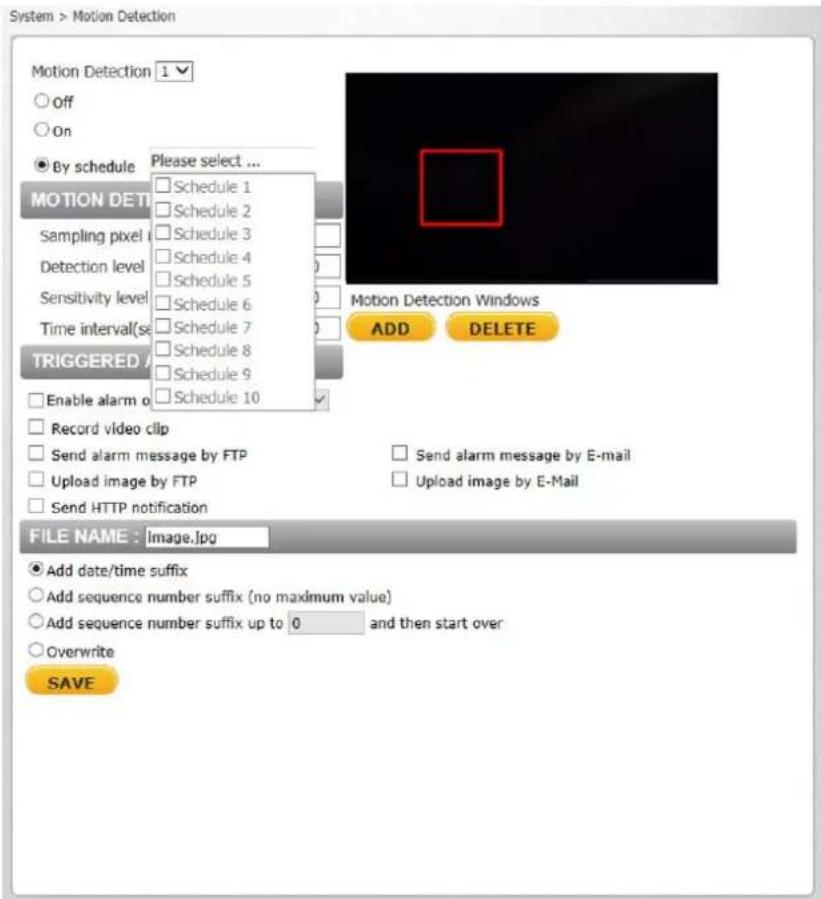
Figure 70: Moon Detecon Screen – with Schedule Drop-Down Menu
Moon Detecon Windows
Up to 10 Moon Detecon windows can be set. Click the ADD buon under the Live View pane to add a Moon Detection window. To cancel a Moon Detecon window, move the mouse cursor to the selected window and click DELETE.
If the moon detecon funcon is acvated, the following Moon pop-up window appears.
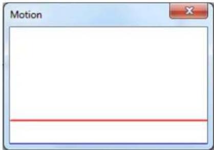
Figure 71: Moon Window without Detecon
When moon is detected, the signals are displayed in the Moon window shown below.
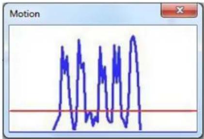
Figure 72: Moon Window with Detecon
Detailed sengs for moon detecon are as follows:
- Sampling pixel interval [1-10] – Select a number from 1-10. The default value is 1. If the value is set as 3, within the detecon region, the system will take one sampling pixel for every 3 pixels by each row and each column (see the gure below).

natural_image
Checkerboard pattern with alternating red and white squares (no text or symbols)Figure 73: Pixel Interval Illustration
- Detecon level [1-100] – Select a number from 1-100. The default level is 40. This sets detecon level for each sampling pixel; the smaller the value, the more sensitive it is.
- Sensitivity level [1-100] – Select a number from 1-100. The default level is 80, which means if 20% or more sampling pixels are detected dierently, the system will detect moon. The bigger the value, the more sensitive it is. When the value is bigger, the red horizontal line in the moon indicates window will be lowered accordingly.
- Time interval (sec) [0-7200] – Select a number from 0-7200 (seconds). The default interval is 10. The value is the interval between each detected moon.
Triggered Acon
The Administrator can specify alarm acons to be taken when moon is detected. See Figure 69: Moon Detecon Screen. The opons are listed as follows:
- Enable alarm output – Check this box and select the predened type of alarm output (low or high) to enable alarm relay when tampering is detected.
- Record video clip – Select this box to store the moon detecon alarm recording in a microSDXC card or on the NAS when tampering is detected. Enter the number of seconds for the pre-trigger buer. Select the rst radial buon to upload for a specied length of me and enter the number of seconds. Alternatively, select the second radial buon to upload during the acve trigger.

Note:
Make sure the local recording (with microSDXC card) is acvated so that this funcon can be implemented. See Recording for further details.
- Send alarm message by FTP – Select whether to send an alarm message by FTP when moon is detected.
- Upload image by FTP – Select this box in order to upload an image to a designated FTP site when moon is detected according to various parameters, as seen in Figure 53: Upload Image by FTP.

Note:
Images can be sent by FTP only when MJPEG is selected as the video stream from the Video Format screen.
Specify the FTP address to use from the drop-down menu. Select the number of frames for the pre-trigger and post-trigger buers from the drop-down menu of 1-20 frames.
Check the box for Connue image upload if you wish to use this opon. To specify the length of me for the upload, click this radial buon and enter the number of seconds. To upload while the trigger is acve, click this radial buon. Finally, select the number of frames per second from the drop-down menu next to Image frequency.
- Send HTTP nocoon – Check this box to send a nocoon by HTTP. Select the desnaon HTTP address from the drop-down menu and specify the parameters for event nocoons by moon detecon triggered. When an alarm is triggered, the nocoon will be sent to one of two specied HTTP servers. See Figure 54: Send HTTP Nocoon.
- Send alarm message by E-Mail – Select whether to send an alarm message by e-mail when moon is detected.

Note:
Make sure that local recording (with a microSDXC card) is acvated so that this funcon can be implemented. See Recording for further details.
- Upload image by E-Mail – Select this box in order to assign an e-mail address and congregate various parameters, as seen in Figure 56: Upload Image by E-Mail.

Note:
Images can be sent by e-mail only when MJPEG is selected as the video stream from the Video Format screen.
When moon is detected, event images are sent to one of two designated e-mail addresses. Select the number of frames for the pre-trigger and post-trigger buers from the drop-down menu of 1-20 frames.
Check the box for Connue image upload to use this opon. To specify the length of me for the upload, click this radial buon and enter the number of seconds. To upload while the trigger is acve, click this radial buon. Finally, select the number of frames per second from the drop-down menu next to Image frequency.

Note:
Make sure that SMTP or FTP conguraon has been completed. See the Mail and FTP seconds for further details.
File Name
The uploaded image's lename format is set in this secon. Select one that meets your requirements.
Click SAVE to save the moon detecon sengs.
9.3.7 Schedule
The Schedule screen is used by the network failure detecon, tampering and moon detecon funcons. To access the schedule funcon, open the Main window, select the System tab, and click the Schedule tab. The funcons in this tab allow administrators to create customized schedules for the camera. If a schedule exists, the administrator can apply that schedule to this camera using the available dropdown. See Figure 74: Schedule Screen.

Note:
This applicaon is not the same as the Recording Schedule funcon.
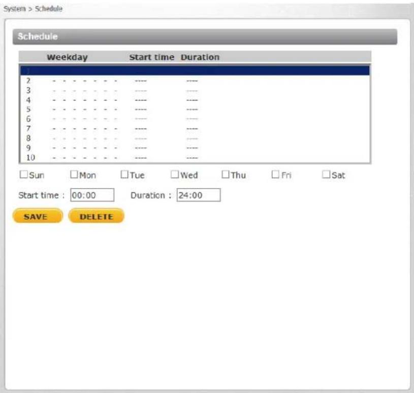
Figure 74: Schedule Screen
To create a new schedule or edit an existing schedule
- Select the appropriate checkbox for the day(s) of the week (Sun, Mon, Tue, Wed, Thu, Fri and Sat) to create a schedule.
- Set Start me (for example, 09:00) and Duraon (for example, 4:00 hours).
- Click SAVE to apply the newly created schedule to the camera.
To remove a schedule
- To remove a schedule, select the setup data line by line.
- Click DELETE to remove.
9.3.8 File Locaon
From the File Locaon page, specify a storage locaon for snapshots and web recordings. The default seng is: C:. Aer conming the setng, click SAVE to save the snapshots and recordings in the designated locaon.

Figure 75: File Locaon Screen

Note:
Make sure the selected le path contains valid characters.
9.3.9 Maintenance
Clicking the Maintenance tab in the System screen opens a drop-down menu with the following tabs:
- Log File
- User
Informaon
- Factory
Default
- Soware
Version
- Soware
Upgrade
- Parameters
9.3.9.1 Log File
Click Log le to view the system log le. The content of the le provides informaon about connecons aer system boot-up.
![[Fri Apr 2 22:17:00 2010] --Network interface initialized start [Fri Apr 2 22:17:07 2010] --Network interface initialized end [Fri Apr 2 22:17:07 2010] --Host IP = 172.19.7.71 [Fri Apr 2 22:17:07 2010] --Subnet Mask = 255.255.255.0 [Fri Apr 2 22:17:07 2010] --Gateway = 172.19.7.2 [Fri Apr 2 22:17:07 2010] --MAC address = 00:1B:D8:80:35:D8 [Fri Apr 2 22:17:27 2010] --Admin@::ffff:172.20.12.104 GET / HTTP/1.1 [Fri Apr 2 22:17:27 2010] --Admin@::ffff:172.20.12.104 GET /cgi-bin/setlogout.cgi H [Fri Apr 2 22:17:30 2010] --Admin@::ffff:172.20.12.104 GET /cgi-bin/mainhtml.cgi H [Fri Apr 2 22:17:31 2010] --Admin@::ffff:172.20.12.104 GET /cgi-bin/center.cgi HTTF [Fri Apr 2 22:17:34 2010] --Admin@::ffff:172.20.12.104 GET /cgi-bin/showdate.cgi H [Sat Apr 3 02:59:27 2010] --Admin@::ffff:172.19.7.95 GET /cgi-bin/admin/param.cgi [Sat Apr 3 02:59:27 2010] --Admin@::ffff:172.19.7.95 GET /cgi-bin/admin/param.cgi [Sat Apr 3 03:00:01 2010] --Admin@::ffff:172.19.7.95 GET /cgi-bin/admin/param.cgi [Sat Apr 3 03:00:01 2010] --Admin@::ffff:172.19.7.95 GET /cgi-bin/admin/param.cgi [Sat Apr 3 03:45:27 2010] --Admin@::ffff:172.19.7.95 GET /cgi-bin/admin/param.cgi [Sat Apr 3 03:45:27 2010] --Admin@::ffff:172.19.7.95 GET /cgi-bin/admin/param.cgi [Sat Apr 3 05:14:16 2010] --Admin@::ffff:172.19.7.80 GET /cgi-bin/admin/param.cgi [Sat Apr 3 05:14:16 2010] --Admin@::ffff:172.19.7.80 GET /cgi-bin/admin/param.cgi [Sat Apr 3 06:06:15 2010] --Admin@::ffff:172.19.7.80 GET /cgi-bin/admin/param.cgi [Sat Apr 3 06:06:15 2010] --Admin@::ffff:172.19.7.80 GET /cgi-bin/admin/param.cgi [Sat Apr 3 23:21:23 2010] --Admin@::ffff:172.19.7.80 GET / HTTP/1.1 [Sat Apr 3 23:21:23 2010] --Admin@::ffff:172.19.7.80 GET /cgi-bin/setlogout.cgi HTT [Sat Apr 3 23:21:23 2010] --Admin@::ffff:172.19.7.80 GET /cgi-bin/mainhtml.cgi HT-](/content/2026/05/980486/images/4c0bab5e79297780d50af274144867d013da2d67f3924d6104b430305ff473fe.jpg)
Figure 76: Log File Screen
9.3.9.2 User Informaon
The Administrator can view each user's login informaon and privileges in the User informaon screen shown below.

Note:
User credenals and privileges are set in the User screen (page 33).
View User Login Informaon
Click GET USER INFORMATION to see each user's details. For example: Admin: 1234. This indicates that the user's login username is Admin and the password is 1234.
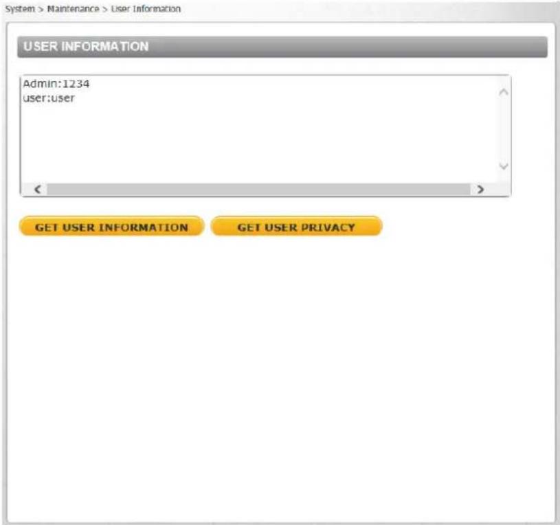
Figure 77: User Informaon Screen – Get User Informaon
View User Privilege
Click GET USER PRIVACY to view each user's privileges.

Figure 78: User Informaon – Get User Privacy
In the screen above, both Admin and User are granted privileges of I/O access, Camera control, Talk and Listen, which are the maximum privileges that can be granted.

9.3.9.3 Factory Default
The Factory default page is shown below. Follow the instrucons to reset the camera to factory default sengs if needed.

Figure 79: Factory Default Screen
Full Restore
Click FULL RESTORE to restore the factory default sengs. The system restarts in 30 seconds.

Note:
The IP address and all other sengs will be restored to factory default sengs.
Paral Restore
Click PARTIAL RESTORE to restore the factory default sengs, but save the network sengs. The system restarts in 30 seconds.

Figure 80: Paral Restore Screen
Reboot
Click REBOOT to restart the system without changing current sengs.
9.3.9.4 Soware Version
The current version of the soware is displayed in the Soware Version screen.

Figure 81: Soware Version Screen
9.3.9.5 Soware Upgrade
The Soware Upgrade screen enables you to select a soware le to upload.

Figure 82: Upgrade Screen

Note:
Make sure that the soware upgrade le is available before performing a soware upgrade.
To upgrade the soware
- In the Step 1 text box, click Browse and select the binary le to be uploaded, for example, uImage+userland.img.

Note:
Do not change the le name. If you change the upgrade le name, the system will fail to nd the le.
- From the drop-down menu of binary les in Step 2, select the le to upgrade. In the above example uImage+userland.img is selected.
- Click UPGRADE. The system varies that the upgrade le exists and begins to upload the le. The upgrade status bar is displayed on the page. When the upgrade process is completed, the Live page is displayed.
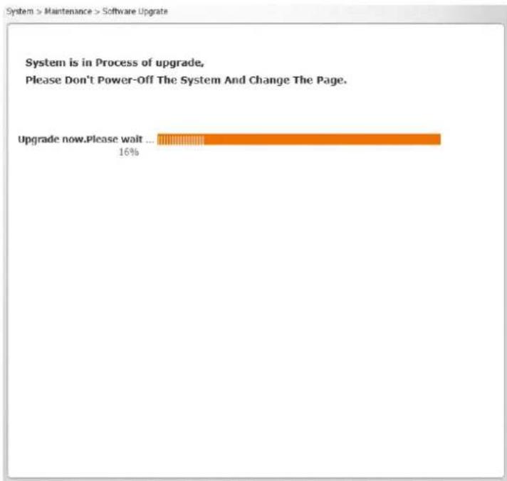
bar
System is in Process of upgrade, Please Don't Power-Off The System And Change The Page. Upgrade now.Please wait ... 16%Figure 83: Soware Upgrade – In Process
- Close the video browser.
- From the Windows Start menu, select Control Panel.
- Select Uninstall a Program.
- In the Currently installed programs list, select DVPlayer.
- Click Uninstall to delete the exisng DVPlayer.
- Install the new DVPlayer AcveX plug-in.

Warning:
Do not unplug power while upgrading the soware.
Averssement:
Figure 84: Parameter Screen

Note:
Slide the sidebar located on the right of the screen to view the enre list of parameters.
From the Import/Export screen you can export conguraon les to a specied locaon and retrieve data by uploading an exisng conguraon le to the camera.

Figure 85: Import/Export Screen
Export
You can save system sengs by exporng the conguraon le (.bin) to a specied locaon for future use. Click EXPORT and the popup window File Download appears as shown below.

Figure 86: File Download Screen
Click Save and specify a locaon to save the conguraon le.

Warning:
Do not unplug power while changing le names.
Averssement:
To copy an exisng conguraon le to the camera, click Browse to select the conguraon le, and then click UPLOAD to upload the le.

Warning:
Do not unplug power while changing le names.
Averssement:
Select the Streaming tab in the navigaon bar at the top of the page to display the congorable video and audio selecons in the sidebar. From the Streaming sidebar, the Administrator can congregate a specific video resolution, video compression mode, video protocol, audio transmission mode, etc. Details of these sengs are specified in the following seconds.
- Video Format
• Video Compression
• Video ROI Encoding
• Video OCX Protocol
• Video Frame Rate
- Video Mask
- Audio

Figure 87: Streaming Secon Tabs
9.4.1 Video Format
From the Video Format screen, you can congregate the following sengs:
• Video Resoluon Sengs
• Text Overlay Sengs
- Video Rotate Type
• GOV Sengs
• H.264 Prole
CB-6204 cameras support three video streams.

Figure 88: CB-6204 Video Format Screen
CB-6208 cameras support four video streams.

Figure 89: CB-6208 Video Format Screen
9.4.1.1 CB-6204 Video Resoluon Sengs
The following video resoluons are supported:
■ H.264-Only
■ MJPEG-Only
■ H.264 + H.264 and H.264 + MJPEG
■ H.264 + H.264 + H.264 and H.264 + H.264 + MJPEG
| H.264-Only | ||
| TV System | Stream 1 | BNC Support |
| WDR3 | 2560 x 1440 (12/15 fps) | Y |
| WDR2 | 2560 x 1440 (25/30 fps) | Y |
| WDR2/3 | 1280 x 720 (25/30 fps) | Y |
| WDR2/3 | 720 x 576 (25 fps)720 x 480 (30 fps) | Y |
9.4.1.1.2 MJPEG-Only
| MJPEG-Only | ||
| TV System | Stream 1 | BNC Support |
| WDR2/3 | 1920 x 1080 (25/30 fps) | Y |
| WDR2/3 | 1280 x 720 (25/30 fps) | Y |
| WDR2/3 | 720 x 576 (25 fps)720 x 480 (30 fps) | Y |
9.4.1.1.3 H.264 + H.264 and H.264 + MJPEG
| H.264 + H.264/MJPEG | |||
| TV System | Stream 1 | Stream 2 | BNC Support |
| WDR2 | 2560 x 1440 (12/15 fps) | 1280 x 720 (12/15 fps) | NA |
| WDR3 | 2560 x 1440 (12/15 fps) | 1280 x 720 (12/15 fps) | NA |
| 720 x 576 (12 fps)720 x 480 (15 fps) | |||
| WDR2 | 2560 x 1440 (25/30 fps) | 720 x 576 (25 fps)720 x 480 (30 fps) | NA |
| WDR2/3 | 1280 x 720 (25/30 fps) | 1280 x 720 (25/30 fps) | NA |
| 720 x 576 (25 fps)720 x 480 (30 fps) | |||
| WDR2/3 | 720 x 576 (25 fps)720 x 480 (30 fps) | 720 x 576 (25 fps)720 x 480 (30 fps) | NA |
9.4.1.1.4 H.264 + H.264 + H.264 and H.264 + H.264 + MJPEG
| H.264 + H.264 + H.264/MJPEG | ||||
| TV System | Stream 1 | Stream 2 | Stream 3 | BNC Support |
| WDR2/3 | 2560 x 1440 (12/15 fps) | 1280 x 720 (12/15 fps) | 720 x 576 (12 fps) | NA |
| 720 x 576 (12 fps) | 720 x 480 (15 fps) | |||
| 720 x 480 (15 fps) | ||||
| WDR2/3 | 1280 x 720 (25/30 fps) | 1280 x 720 (25/30 fps) | 1280 x 720 (25/30 fps) | NA |
| 720 x 576 (25 fps) | ||||
| 720 x 480 (30 fps) | ||||
| 720 x 576 (25 fps) | 720 x 576 (25 fps) | |||
| 720 x 480 (30 fps) | 720 x 480 (30 fps) | |||
| WDR2/3 | 720 x 576 (25 fps) | 720 x 576 (25 fps) | 720 x 576 (25 fps) | NA |
| 720 x 480 (30 fps) | 720 x 480 (30 fps) | 720 x 480 (30 fps) | ||
9.4.1.2 CB-6208 Video Resoluon Sengs
The following video resolutions are supported:
■ H.264-Only
■ MJPEG-Only
■ H.264 + H.264
■ H.264 + MJPEG
■ H.264 + H.264 + H.264 and H.264 + H.264 + MJPEG
■ H.264 + H.264 + H.264 + H.264 and H.264 + H.264 + H.264 + MJPEG
| MJPEG-Only | ||||
| PAL @ 25 FPS | NTSC @ 30 FPS | PAL @ 50 FPS | NTSC @ 60 FPS | BNC Support |
| 1920 x 1080 (25 fps) | 1920 x 1080 (30 fps) | 1920 x 1080 (50 fps) | 1920 x 1080 (60 fps) | Y |
| 1280 x 720 (25 fps) | 1280 x 720 (30 fps) | 1280 x 720 (50 fps) | 1280 x 720 (60 fps) | Y |
| 720 x 576 (25 fps) | 720 x 480 (30 fps) | 720 x 768 (50 fps) | 720 x 480 (60 fps) | Y |
9.4.1.2.3 H.264 + H.264 and H.264 + MJPEG
| H.264 + H.264/MJPEG (PAL @ 25 FPS) | ||
| Stream 1 | Stream 2 | BNC Support |
| 3840 x 2160 (12 fps) | 1920 x 1080 (12 fps) | Y on H.264-2N on MJPEG |
| 3840 x 2160 (20 fps) | 1280 x 720 (20 fps) | N |
| 720 x 576 (20 fps) | Y | |
| 1920 x 1080 (25 fps) | 1920 x 1080 (25 fps) | N |
| 1280 x 720 (25 fps) | N | |
| 720 x 576 (25 fps) | Y | |
| 1280 x 720 (25 fps) | 1280 x 720 (25 fps) | N |
| 720 x 576 (25 fps) | Y | |
| 720 x 576 (25 fps) | 720 x 576 (25 fps) | Y |
| H.264 + H.264/MJPEG (NTSC @ 30 FPS) | ||
| Stream 1 | Stream 2 | BNC Support |
| 3840 x 2160 (15 fps) | 1920 x 1080 (15 fps) | N |
| 3840 x 2160 (20 fps) | 1280 x 720 (20 fps) | N |
| 720 x 480 (20 fps) | Y | |
| 1920 x 1080 (30 fps) | 1920 x 1080 (30 fps) | N |
| 1280 x 720 (30 fps) | N | |
| 720 x 480 (30 fps) | Y | |
| 1280 x 720 (30 fps) | 1280 x 720 (30 fps) | N |
| 720 x 480 (30 fps) | Y | |
| 720 x 480 (30 fps) | 720 x 480 (30 fps) | Y |
| H.264 + H.264/MJPEG (PAL @ 50 FPS) | ||
| Stream 1 | Stream 2 | BNC Support |
| 1920 x 1080 (50 fps) | 1280 x 720 (50 fps) | N |
| 720 x 576 (50 fps) | Y | |
| 1280 x 720 (50 fps) | 1280 x 720 (50 fps) | N |
| 720 x 576 (50 fps) | Y | |
| 720 x 576 (50 fps) | 720 x 576 (50 fps) | Y |
| H.264 + H.264/MJPEG (NTSC @ 60 FPS) | ||
| Stream 1 | Stream 2 | BNC Support |
| 1920 x 1080 (60 fps) | 1280 x 720 (60 fps) | N |
| 720 x 480 (60 fps) | Y | |
| 1280 x 720 (60 fps) | 1280 x 720 (60 fps) | N |
| 720 x 480 (60 fps) | Y | |
| 720 x 480 (60 fps) | 720 x 480 (60 fps) | Y |
9.4.1.2.4 H.264 + H.264 + H.264 and H.264 + H.264 + MJPEG
| H.264 + H.264 + H.264/MJPEG (PAL @ 25 FPS) | ||
| Stream 1 | Stream 2 | Stream 3 |
| 3840 x 2160 (12 fps) | 1920 x 1080 (12 fps) | 720 x 576 (12 fps) |
| 1920 x 1080 (25 fps) | 1280 x 720 (25 fps) | 1280 x 720 (25 fps) |
| 720 x 576 (25 fps) | 720 x 576 (25 fps) | |
| 1280 x 720 (25 fps) | 1280 x 720 (25 fps) | 1280 x 720 (25 fps) |
| 720 x 576 (25 fps) | 720 x 576 (25 fps) | |
| 720 x 576 (25 fps) | 720 x 576 (25 fps) | 720 x 576 (25 fps) |
| H.264 + H.264 + H.264/MJPEG (NTSC @ 30 FPS) | ||
| Stream 1 | Stream 2 | Stream 3 |
| 3840 x 2160 (15 fps) | 1920 x 1080 (15 fps) | 720 x 480 (15 fps) |
| 1920 x 1080 (30 fps) | 1280 x 720 (30 fps) | 1280 x 720 (30 fps) |
| 720 x 480 (30 fps) | 720 x 480 (30 fps) | |
| 1280 x 720 (30 fps) | 1280 x 720 (30 fps) | 1280 x 720 (30 fps) |
| 720 x 480 (30 fps) | 720 x 480 (30 fps) | |
| 720 x 480 (30 fps) | 720 x 480 (30 fps) | 720 x 480 (30 fps) |
| H.264 + H.264 + H.264/MJPEG (PAL @ 50 FPS) | ||
| Stream 1 | Stream 2 | Stream 3 |
| 1920 x 1080 (50 fps) | 1280 x 720 (50 fps) | 720 x 576 (50 fps) |
| 720 x 576 (50 fps) | ||
| 1280 x 720 (50 fps) | 1280 x 720 (50 fps) | 720 x 576 (50 fps) |
| 720 x 576 (50 fps) | ||
| 720 x 576 (50 fps) | 720 x 576 (50 fps) | 720 x 576 (50 fps) |
| H.264 + H.264 H.264/MJPEG (NTSC @ 60 FPS) | ||
| Stream 1 | Stream 2 | Stream 3 |
| 1920 x 1080 (60 fps) | 1280 x 720 (60 fps) | 720 x 480 (60 fps) |
| 720 x 480 (60 fps) | ||
| 1280 x 720 (60 fps) | 1280 x 720 (60 fps) | 720 x 480 (60 fps) |
| 720 x 480 (60 fps) | ||
| 720 x 480 (60 fps) | 720 x 480 (60 fps) | 720 x 480 (60 fps) |
9.4.1.2.5 H.264 + H.264 + H.264 + H.264 and H.264 + H.264 + H.264 + MJPEG
| H.264 + H.264 + H.264 + H.264/MJPEG (PAL @ 25 FPS) | |||
| Stream 1 | Stream 2 | Stream 3 | Stream 4 |
| 3840 x 2160 (12 fps) | 1920 x 1080 (12 fps) | 1280 x 720 (12 fps) | 720 x 576 (12 fps) |
| 720 x 576 (12 fps) | |||
| 1280 x 720 (12 fps) | 1280 x 720 (12 fps) | ||
| 720 x 576 (12 fps) | |||
| 720 x 576 (12 fps) | 720 x 576 (12 fps) | ||
| 1920 x 1080 (25 fps) | 1920 x 1080 (25 fps) | 1280 x 720 (25 fps) | 720 x 576 (25 fps) |
| 720 x 576 (25 fps) | |||
| 1280 x 720 (25 fps) | 1280 x 720 (25 fps) | ||
| 720 x 576 (25 fps) | |||
| 720 x 576 (25 fps) | 720 x 576 (25 fps) | ||
| 1280 x 720 (25 fps) | 1280 x 720 (25 fps) | 1280 x 720 (25 fps) | 720 x 576 (25 fps) |
| 720 x 576 (25 fps) | |||
| 720 x 576 (25 fps) | 720 x 576 (25 fps) | ||
| 720 x 576 (25 fps) | 720 x 576 (25 fps) | 720 x 576 (25 fps) | 720 x 576 (25 fps) |
| H.264 + H.264 + H.264 + H.264/MJPEG (NTSC @ 30 FPS) | |||
| Stream 1 | Stream 2 | Stream 3 | Stream 4 |
| 3840 x 2160 (15 fps) | 1920 x 1080 (15 fps) | 1280 x 720 (15 fps) | 720 x 480 (15 fps) |
| 720 x 480 (15 fps) | |||
| 1280 x 720 (15 fps) | 1280 x 720 (15 fps) | ||
| 720 x 480 (15 fps) | |||
| 720 x 480 (15 fps) | 720 x 480 (15 fps) | ||
| 1920 x 1080 (30 fps) | 1920 x 1080 (30 fps) | 1280 x 720 (30 fps) | 720 x 480 (30 fps) |
| 720 x 480 (30 fps) | |||
| 1280 x 720 (30 fps) | 1280 x 720 (30 fps) | ||
| 720 x 480 (30 fps) | |||
| 720 x 480 (30 fps) | 720 x 480 (30 fps) | ||
| 1280 x 720 (30 fps) | 1280 x 720 (30 fps) | 1280 x 720 (30 fps) | 720 x 480 (30 fps) |
| 720 x 480 (30 fps) | |||
| 720 x 480 (30 fps) | 720 x 480 (30 fps) | ||
| 720 x 480 (30 fps) | 720 x 480 (30 fps) | 720 x 480 (30 fps) | 720 x 480 (30 fps) |
H.264 + H.264 + H.264 + H.264/MJPEG (PAL @ 50 FPS)
| Stream 1 | Stream 2 | Stream 3 | Stream 4 |
| 1920 x 1080 (50 fps) | 1280 x 720 (50 fps) | 1280 x 720 (25 fps) | 720 x 576 (25 fps) |
| 720 x 576 (50 fps) | 720 x 576 (50 fps) | ||
| 720 x 576 (50 fps) | 720 x 576 (50 fps) | 720 x 576 (50 fps) | |
| 1280 x 720 (50 fps) | 1280 x 720 (50 fps) | 1280 x 720 (50 fps) | 720 x 576 (50 fps) |
| 720 x 576 (50 fps) | 720 x 576 (50 fps) | ||
| 720 x 576 (50 fps) | 720 x 576 (50 fps) | 720 x 576 (50 fps) | 720 x 576 (50 fps) |
H.264 + H.264 + H.264 + H.264/MJPEG (NTSC @ 60 FPS)
| Stream 1 | Stream 2 | Stream 3 | Stream 4 |
| 1920 x 1080 (60 fps) | 1280 x 720 (60 fps) | 1280 x 720 (30 fps) | 720 x 480 (30 fps) |
| 720 x 480 (60 fps) | 720 x 480 (60 fps) | ||
| 720 x 480 (60 fps) | 720 x 480 (60 fps) | 720 x 480 (60 fps) | |
| 1280 x 720 (60 fps) | 1280 x 720 (60 fps) | 1280 x 720 (60 fps) | 720 x 480 (60 fps) |
| 720 x 480 (60 fps) | |||
| 720 x 480 (60 fps) | 720 x 480 (60 fps) | ||
| 720 x 480 (60 fps) | 720 x 480 (60 fps) | 720 x 480 (60 fps) | 720 x 480 (60 fps) |
9.4.1.3 Text Overlay Sengs
Select the relevant checkbox for the data to include in the on-screen display:
■ Include date
■ Include me
- Include text string – when this checkbox is selected, enter the string in the text box that opens.
- Include subtle – when this checkbox is selected, enter the string in the text box that opens.
9.4.1.4 Video Rotate Type
You can change video display type if necessary. Selectable video rotate types include Normal video, Flip video, Mirror video, and 180 degree rotate. Dierences among these types are illustrated below. Suppose the displayed image of the camera is shown as follows.
Figure 90: View-1 (Source)
To rotate the image vercally, for example, select Flip video. The displayed image is reversed as shown below.
Figure 91: View-2 Image Rotated Vercally (Reversed)
Following are descripons of dierent video rotate types.
- Normal video – The image appears as it is viewed. This is the default seng.
- Flip video – The image is reversed along its horizontal axis.
- Mirror video – The image is reversed along its vercal axis.
■ 180 degree rotate – The image rotates 180irc counter-clockwise (to the le).
Click SAVE to conrm the seng.
9.4.1.5 GOV Sengs
Users can set the GOV length to determine the frame structure (I-frames and P-frames) in a video stream for saving bandwidth. The seng range is from 2 to 64. A longer GOV means decreasing the frequency of I-frames. The default GOV seng for H.264-1 and H.264-2 is 60. The default GOV seng for H.264-3 and H.264-4 (CB-6208) is 30. Click SAVE to conrm the GOV seng.
9.4.1.6 H.264 Prole
The H.264 standard denes 21 sets of capabilities. These are referred to as proles and they target specific classes of applicants. In the security industry, the most common are as follows:
- Baseline Prole (BP)
Primarily for low-cost applicaons that require additional data loss robustness, Baseline Prole is used in some videoconferencing and mobile applicaons. This is the most common prole used in IP security cameras due to the low computational cost of processing the video using this prole.
- Main Prole (MP)
This prole provides improved picture quality at reduced bandwidths and storage costs and is becoming more common as the camera processors (DSPs) become more able to handle the processing load. Main Prole can save 10-12% over Baseline. This is the default prole.
• High Prole (HP)
High Prole is the primary prole for HD broadcast applicaons. It can save 10-12% of the storage cost over Main Prole. However, it may also increase video latency, depending on the stream structure. Quasar Gen II models default to the Main Prole to provide the best trade-o between storage size and video latency.
Click SAVE to conrm the sengs.
9.4.2 Video Compression
From the Video Compression page, you can specify MJPEG and H.264 compression sengs.
CB-6204 cameras support three video streams.
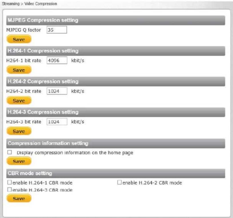
Figure 92: CB-6204 Video Compression Screen
CB-6208 cameras support four video streams.

Figure 93: Video Compression Screen
MJPEG Compression Seng
A higher value implies higher bit rates and higher visual quality. The default seng of the MJPEG Q factor is 35. The seng range is from 1 to 70. Click SAVE to conrm the seng.
H.264 Compression Seng
The default seng of H.264-1 is 4096. The default setng for the other streams is 1024 kbps. Each stream can be congured individually. The seng range is from 64 to 20,480 kbps. Click SAVE to conrm the seng.

Note:
A total of 26,624 kbps is available on the camera for streaming. A single stream is limited to 20,480 kbps
CBR Mode Seng
If available bandwidth is limited, select CBR (Constant Bit Rate) mode. To operate the camera in Variable Bit Rate (VBR) mode, uncheck the CBR checkbox. Click SAVE to conrm the seng.

Note:
CBR mode aects image quality.
9.4.3 Video ROI Encoding
It is possible to congregate Region of Interest sengs for three (CB-6204) or four (CB-6208) H.264 streams on the Video ROI Encoding screen. The image displayed within the ROI box can be displayed with a higher bit rate and quality than the image outside of the box. Overall bit rate is not acted by selecng Regions of Interest. Enhancing the video where the quality is very important consumes more bandwidth, but enables lowering image quality and bandwidth consumption on less important zones in the scene.

Figure 94: Video ROI Encoding Screen
To use ROI encoding
- From the Video Stream drop-down menu, select the H.264 stream. Three streams are available on CB-6204 cameras. Four streams are available on CB-6208 cameras.
- From the ROI Encoding drop-down menu, select Enable to acvate this funcon.
- From the Quality drop-down menu, select a number between -15 (lowest image quality) to +15 (highest image quality) or default (where the image quality of the video in the box is the same as the image quality outside the box).
- Click SAVE when nished.
- Drag the box in the ROI Encoding Window to cover the zone for which you want to acvate ROI encoding.
- Click ADD to create a new zone or DELETE to remove a zone.
- Click SAVE when nished.
9.4.4 Video OCX Protocol
From the Video OCX Protocol page, you can select various protocols for streaming media over the network. In the case of mulcast networking, select Mulcast mode. Three streams are available on CB-6204 cameras. Four streams are available on CB-6208 cameras.

Figure 95: Video OCX Protocol Screen
Video OCX protocol seng opons include:
■ RTP over UDP
■ RTP over RTSP (TCP)
■ RTSP over HTTP
■ MJPEG over HTTP
- Mulcast mode – Enter in each eld all required data, including Mulcast H.264-1 Video Address, Mulcast H.264-2 Video Address, Mulcast H.264-3 Video Address, Mulcast H.264-4 Video Address (CB-6208 only), Mulcast MJPEG Video Address, Mulcast Audio Address, and Mulcast TTL.
Click SAVE to conrm the sengs.
9.4.5 Video Frame Rate
From the Video Frame Rate screen, you can specify the frames per second (fps) for each video compression format. CB-6204 includes three streams. CB-6208 includes four streams.

Figure 96: Video Frame Rate Screen
MJPEG/H.264 Frame Rate Seng
When operang the unit in H.264-only mode, the default frame is 30 fps in NTSC and 25 fps in PAL.

Note:
A lower frame rate decreases video smoothness.
The following sengs apply when operang the unit in any mode other than H.264-only:
- MJPEG – The seng range of the MJPEG Frame Rate is from 1 to 60 in NTSC and 1 to 50 in PAL. The default seng is 30 fps in NTSC and 25 fps in PAL.
- H.264-1 – The seng range for the H-264-1 Frame Rate is from 1 to 15 in NTSC and 1 to 12 in PAL. The default seng is 15 fps in NTSC and 12 fps in PAL.
■ H.264-2 – The seng range for the H-264-2 Frame Rate is from 1 to 15 in NTSC and 1 to 12 in PAL. The default seng is 15 fps in NTSC and 12 fps in PAL. - H.264-3 – The seng range for the H-264-3 Frame Rate is from 1 to 30 in NTSC and 1 to 50 in PAL. The default seng is 15 fps in NTSC and 12 fps in PAL.
■ H.264-4 (CB-6208 only)—The seng range for the H-264-4 Frame Rate is from 1 to 30 in NTSC and 1 to 50 in PAL. The default seng is 15 fps in NTSC and 12 fps in PAL.
Click SAVE to conrm the sengs.
9.4.6 Video Mask
From the Mask screen, you may select up to ve rectangular porons of the View Area to 'Mask.' Below is an illustraon with the maximum ve masks displayed in the View Area, the last (h) one selected being highlighted in red.

Figure 97: Mask Screen
Acve Mask Funcon
When a Video [Privacy] Mask is turned on, the area within the mask or box is blocked out or obscured from view.
To enable a mask
- Check a Video Mask checkbox. A red frame is displayed in the Live Video pane on the right side.
- Use the mouse to drag and drop, adjust the mask's size, and place it on the target zone.

Note:
It is suggested to set the Video Mask twice as large as the object it covers.
To disable a mask
- Uncheck the checkbox of the Video Mask meant to be deleted. The selected mask disappears from the Live Video pane.
Mask Seng
- Mask color – The selecons of Mask color include red, black, white, yellow, green, blue, cyan, and magenta.
Click SAVE to conrm the seng.
9.4.7 Audio
From the Audio screen you can select the Transmission Mode, Server Gain, Bit Rate, and enable or disable storage of the audio recording.

Figure 98: Audio Screen
Transmission Mode
- Full-duplex (Talk and listen simultaneously) – In the Full-duplex mode, the local and remote sites can communicate with each other simultaneously, i.e. both sites can speak and be heard at the same me.
- Half-duplex (Talk or listen, not at the same me) – In the Half-duplex mode, the local or remote site can only talk or listen to the other site at one me.
- Simplex (Talk only) – In the Talk only Simplex mode, the local/remote site can only talk to the other site.
- Simplex (Listen only) – In the Listen only Simplex mode, the local/remote site can only listen to the other site.
■ Disable – Select this opon to turn o the audio transmission funcon.
Server Gain Seng
Set the audio input/output gain levels for sound amplicaon. The audio gain values are adjustable from 1 to 6. The sound will be turned o if the audio gain is set to Mute.
Bit Rate
Selectable audio transmission bit rate include 16 kbps (G.726), 24 kbps (G.726), 32 kbps (G.726), 40 kbps (G.726), μLAW (G.711) and ALAW (G.711). Both μLAW and ALAW signify 64 kbps, but in dierent compression formats. A higher bit rate enables higher audio quality, but requires higher bandwidth.

Note:
Latitude does not support G.726.
Click SAVE to conrm the sengs.
Recording to Storage
This funcon enables recording of the audio on the SD card and NAS. The Recording to Storage funcon may be enabled or disabled in the Audio screen. The default seng is Disabled.

Note:
This funcon works only if the Recording to Storage opon has been selected or if the Schedule opon has been set.
Click SAVE to conrm the sengs.
9.5 Camera Sengs
From the Camera tab, the administrator can adjust any of the camera sengs from the following tabs:
- Exposure
• Picture Adjustment
• Advanced Picture Sengs
- IR Funcon
- Miscellaneous

Figure 99: Camera Secon Tabs
Every screen in the Camera secon includes the following pushbuons to the le of the Live View window:
| Zoom |  |  |  | Click the Wide or Tele Zoom buon to implement connuous zoom adjustment. Click Reset to return the zoom to the default seng. |
| Step |  |  |  | Click the Wide or Tele Step buon to alternate the zoom between wide and telephoto views within a user-dened range of steps, which can be selected from the drop-down menu. |
| Focus |  |  |  | Click the Near or Far Focus buon to implement connuous focus adjustment. Click Reset to return the zoom to the default seng. |
| Step |  |  |  | Click the Near or Far Step buon to alternate the focus between near and far views within a user-dened range, which can be selected from the drop-down menu. |
| AF |  | Click the Push AF buon once to adjust zoom or focus. | ||
9.5.1 Exposure
The Exposure screen is used to congure lens sengs and exposure modes. The exposure is the amount of light received by the image sensor and is determined by the amount of exposure by the sensor (shuer speed), and other exposure parameters.
Administrators may either allow the camera to automatically select an exposure level using a programmed algorithm or choose the level themselves. Even in Auto Mode, a Minimum Shuer Speed may be set from the drop-down menu to ensure a maximum level of exposure. In Manual Mode, the administrator can choose xed shuer speeds from a drop-down menu. The smaller the
number (the higher the shuer speed) that the administrator selects, the lower the exposure level and vice versa.
9.5.1.1 CB-6204 Exposure Screen
The boom secon of the screen enables you to select one of three exposure modes: P-Iris Priority, Auto P-Iris (default), or Manual Mode. Administrators may either allow the camera to automatically select an exposure level using a programmed algorithm or choose the level themselves.

Figure 100: CB-6204 Exposure Screen
P-Iris Priority Mode
In P-iris Priority mode, the iris does not adjust, regardless of the light level. If, however, the light level goes below the P-iris seng, the iris will fully open in a single step if the Auto Adjustment opon is turned on.
The following seng are available:
- Iris Size Seng – Select the following buons
 | The minus (-) buon closes the iris. |
 | The plus (+) buon opens the iris. |
 | The reset buon is for reseng the P-iris |
 | The radial buon is for automacally selecng the opmal iris exposure |
- Auto Adjustment – From the drop-down menu, select On or O. When enabled, if the lighng level falls below the set P-iris level, the iris will jump to its fully-opened posion.
- Min Shuer Speed – When selecng this mode, the camera’s shuer speed automacally achieves a consistent video output level. Users can select a suitable shuer speed according to the environmental luminance.
The shuer speed range is selectable on the drop-down menu from 1/4 to 1/500 sec (NTSC) and 1/3 to 1/425 sec (PAL). The following table lists the opons.
| P-Iris Priority – Min Shutter Speed | |
| PAL | NTSC |
| 1/425 | 1/500 |
| 1/300 | 1/350 |
| 1/215 | 1/250 |
| 1/150 | 1/180 |
| 1/120 | 1/120 |
| 1/100 | 1/100 |
| 1/75 | 1/90 |
| 1/50 | 1/60 |
| 1/25 | 1/30 |
| 1/12 | 1/15 |
| 1/6 | 1/8 |
| 1/3 | 1/4 |
Click SET when you nish conguring the sengs.
Auto P-Iris Mode
Auto-P iris is the default mode. It automacally and smoothly adjusts the iris when the light level drops to a point where it is insufficient to support the P-iris seng. A Minimum Shuer Speed may be set from the drop-down menu to ensure a maximum level of exposure.
The following seng are available:
- Min Shuer Speed – When selecng this mode, the shuer is completely open and the exposure priority is given to the iris. Shuer speed and AGC circuit funcon automacally in cooperang with the iris to achieve a consistent exposure output.
The shuer speed range is from 1/4 to 1/30 sec (NTSC) and 1/3 to 1/25 sec (PAL). The following table lists the opons.
| Auto Iris - Min Shutter Speed | |
| PAL | NTSC |
| 1/25 | 1/30 |
| 1/12 | 1/15 |
| 1/6 | 1/8 |
| 1/3 | 1/4 |
- F Number – Displays the current F-Stop setng.
Click SET when you nish conguring the sengs.
Manual Mode
Manual Mode opens the iris completely with a xed gain to a xed shuer speed. Users can select a suitable shuer speed according to the environmental luminance.
In Manual Mode, the administrator can select a xed shuer speed and gain from drop-down menus. The smaller the shuer speed number (the higher the shuer speed), the lower the exposure level. The higher the gain, the brighter the picture.
Manual mode is used generally where light levels are xed and the auto sengs do not provide the perfect exposure. It is recommended for scenes where there is a xed lighng contrast and a constant, precise exposure is required.
The following seng are available:
- Iris Size Seng – Select the following buons
| The minus (-) buon closes the iris. | |
| The Plus (+) buon opens the iris. | |
| The reset buon is for reseng the P-iris | |
| The radial buon is for automacally selecng the opmal iris exposure |
- Shuer Speed – The xed shuer speed is selectable from 1/4 to 1/10000 sec (NTSC) and 1/3 to 1/10000 sec (PAL). Users should select the suitable shuer speed according to the environmental luminance. The following table lists the opons.
| Manual Mode - Fixed Shutter Speeds | |
| PAL | NTSC |
| 1/10000 | 1/10000 |
| 1/3500 | 1/3000 |
| 1/2500 | 1/2000 |
| 1/1250 | 1/1000 |
| 1/600 | 1/725 |
| 1/425 | 1/500 |
| 1/300 | 1/350 |
| 1/215 | 1/250 |
| 1/150 | 1/180 |
| 1/120 | 1/120 |
| 1/100 | 1/100 |
| 1/75 | 1/90 |
| 1/50 | 1/60 |
| 1/25 | 1/30 |
| 1/12 | 1/15 |
| 1/6 | 1/8 |
| 1/3 | 1/4 |
- Gain – A nominal video signal level is usually 1 volt peak-to-peak for composite video, 0.7 volts for component or RGB video, or 0.3 volts for the chrominance subsecon, at which level a fully saturated picture is transmied to the acceptor. However, for cases where the video signal is attenuated, a low-noise, high-gain analog amplifier is built into quality video processing equipment. This amplifier provides video gain control whereby the video signal can be boosted or reduced. Dark pictures caused by low level lighng are easily adjusted. The Gain drop-down menu turns the video gain O or moves it in steps from 1 to 9.
Click SET when you nish seng the gain.
9.5.1.2 CB-6208 Exposure Screen
The CB-6208 Exposure screen supports two exposure modes: Auto Mode and Manual Mode.
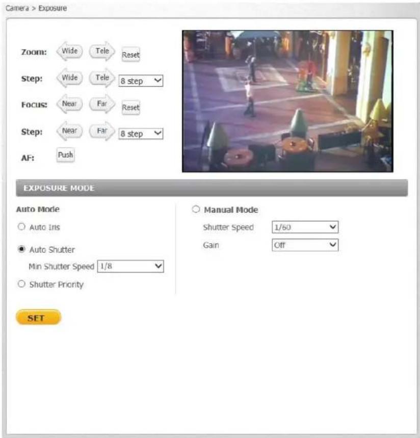
Figure 101: CB-6208 Exposure Screen
Auto Mode
There are three sengs within Auto Mode:
- Auto Iris Min Shuer Speed – When selecng this mode, the shuer is completely open and the exposure priority is given to the iris. Shuer speed and AGC circuit funcon automacally in cooperang with the iris to achieve a consistent exposure output.
The shuer speed range is from 1 to 1/12 sec (NTSC) and 1/1.5 to 1/25 sec (PAL). See the table below showing all the opons.
| Auto Iris - Min Shutter Speed | |
| PAL | NTSC |
| 1/25 | 1/30 |
| 1/12 | 1/15 |
| 1/6 | 1/8 |
| 1/3 | 1/4 |
| 1/1.5 | 1/2 |
| 1 | |
- Auto Shuer Min Shuer Speed – When selecng this mode, the camera's shuer speed works automatically to achieve a consistent video output level. Users can select a suitable shuer speed according to the environmental luminance.
The shuer speed range is from 1 to 1/500 sec (NTSC) and 1/1.5 to 1/425 sec (PAL). See following table, which shows all the opons.
| Auto Shutter – Min Shutter speed | |
| PAL | NTSC |
| 1/425 | 1/500 |
| 1/300 | 1/350 |
| 1/215 | 1/250 |
| 1/150 | 1/180 |
| 1/120 | 1/120 |
| 1/100 | 1/100 |
| 1/75 | 1/90 |
| 1/50 | 1/60 |
| 1/25 | 1/30 |
| 1/12 | 1/15 |
| 1/6 | 1/8 |
| 1/3 | 1/4 |
| 1/1.5 | 1/2 |
| 1 | |
- Shuer Priority – When selecng this mode, a xed exposure is set, while other parameters can change. The shuer speed range is from 1/30 to 1/500 sec (NTSC) and 1/25 to 1/425 sec (PAL). See table below showing all the opons.
| Shutter Priority | |
| PAL | NTSC |
| 1/425 | 1/500 |
| 1/300 | 1/350 |
| 1/215 | 1/250 |
| 1/150 | 1/180 |
| 1/120 | 1/120 |
| 1/100 | 1/100 |
| 1/75 | 1/90 |
| 1/50 | 1/60 |
| 1/25 | 1/30 |
Click SET when you nish seng the shuer speed.
Manual Mode (Fixed Shuer)
Manual Mode opens the iris completely with a xed gain. Users can select a suitable shuer speed according to the environmental luminance. The xed shuer speed is selected from 1 to 1/10000 sec (NTSC) and 1/1.5 to 1/10000 sec (PAL). Users should select suitable shuer speed according to the environmental luminance. See following table, which shows all the opons.
| Manual Mode - Fixed Shutter Speeds | |
| PAL | NTSC |
| 1/10000 | 1/10000 |
| 1/3500 | 1/3000 |
| 1/2500 | 1/2000 |
| 1/1250 | 1/1000 |
| 1/600 | 1/725 |
| 1/425 | 1/500 |
| 1/300 | 1/350 |
| 1/215 | 1/250 |
| 1/150 | 1/180 |
| 1/120 | 1/120 |
| 1/100 | 1/100 |
| 1/75 | 1/90 |
| 1/50 | 1/60 |
| 1/25 | 1/30 |
| 1/12 | 1/15 |
| 1/6 | 1/8 |
| 1/3 | 1/4 |
| 1/1.5 | 1/2 |
| 1 | |
Click SET when you nish seng the shuer speed.
Gain
A nominal video signal level is usually 1 volt peak-to-peak for composite video, 0.7 volts for component or RGB video, or 0.3 volts for the chrominance subsecon, at which level a fully saturated picture is transmied to the acceptor. However, for cases where the video signal is attenuated, a low-noise, high-gain analog amplifier is built into quality video processing equipment. This amplifier provides video gain control whereby the video signal can be boosted or reduced. Dark pictures resulting from low level lighng are easily adjusted.
The Gain drop-down menu enables controlling the video gain from O or in steps from 1 to 9.
Click SET when you nish seng the gain.
9.5.2 Picture Adjustment
Adjustment of some qualities of the video is made possible by selecng Picture Adjustment in the Camera tab. Brightness, Sharpness, Contrast, Saturaon and Hue may all be adjusted via drop-down menus from this window, as shown below.

Figure 102: Camera Sengs Screen – Picture Adjustment
9.5.2.1 Brightness
You can adjust the image's brightness by adjusting this parameter. Select from the range between -12 to +13. To increase video brightness, select a larger number. Click SET to conrm the new seng.
9.5.2.2 Sharpness
Increasing the sharpness level can make the image look sharper, especially enhancing the object's edge. Select from the range between 0 to +15. Click SET to conrm the new seng.
9.5.2.3 Contrast
Camera image contrast level is adjustable. Select from a range of -6 to +19. Click SET to conrm the new seng.
9.5.2.4 Saturaon
Camera image saturaton level is adjustable. Select from a range of -6 to +19. Click SET to conrm the new seng.
9.5.2.5 Hue
Camera image hue level is adjustable: select from a range of -12 to +13. Click SET to conrm the new seng.
9.5.3 Advanced Picture Sengs
9.5.3.1 White Balance
Opons for controlling the camera's white balance (color balance) are shown below.
![Camera > Advance Picture settings Zoom: Wide Tele Reset Step: Wide Tele 8 step Focus: Near Far Reset Step: Near Far 8 step AF: Push Advance Picture settings White Balance ● Auto ○ ATW ○ One Push ○ Manual Rgain [0..127] 57 Bgain [0..127] 54 SET Backlight Off SET WDR function Low Shutter WDR On SET Noise Reduction SPQ+3DNR Low SET](/content/2026/05/980486/images/e298871dfcfe7a5a66aca2c0e7247c9868809713a3e588171575d29571904638.jpg)
Figure 103: Advanced Picture Sengs Screen – White Balance
A camera needs to nd a reference color temperature as a way of measuring the quality of a light source for calculang all other colors. The unit for measuring this rao is in Kelvin (°K) degrees. You can select one of the White Balance control modes according to the operang environment. The table below shows the color temperature of some light sources for reference.
| Light Sources | Color Temperature in K |
| Cloudy Sky | 6,000 to 8,000 |
| Noon Sun and Clear Sky | 6,500 |
| Household Lighng | 2,500 to 3,000 |
| 75-wa Bulb | 2,820 |
| Candle Flame | 1,200 to 1,500 |
Four white balance modes are available:
- Auto – The Auto Balance White mode computes the white balance value output using color informaon from the enre screen. It is suitable for an environment with a light source color temperature in the range of approximately 2,700 \~ 7,500K.
- ATW (Auto Tracking White Balance) – The Auto Tracking White Balance function automacally adjusts the white balance in a scene while temperature color is changing. The ATW Mode is suitable for an environment with a light source color temperature in the range of approximately 2500 \~ 10,000K.
- One Push – This buon acvates the factory-optimized seng for white balance. This seng may not be ideal for every lightng environment.
- Manual – In this mode, you can manually change the white balance value. You can select a number between 0 – 127 for either/both Rgain and Bgain to increase the red and/or blue luminance.
Click SET to conrm the new sengs.
9.5.3.2 Backlight
The Backlight Compensaon funcon prevents the center object from being too dark in surroundings where excessive light is behind the center object. Select On or O.
Click SET to conrm the new sengs.
![Camera > Advance Picture settings Zoom: Wide Tele Reset Step: Wide Tele 8 step Focus: Near Far Reset Step: Near Far 8 step AF: Push Advance Picture settings White Balance ● Auto ○ ATW ○ One Push ○ Manual Rgain [0..127] 57 Bgain [0..127] 54 SET Backlight Off SET WDR function Low Shutter WDR On SET Noise Reduction SPQ+3DNR Low SET](/content/2026/05/980486/images/f84f7ba47ba03cbab24473a614dab01cf49b1e1d0abf46dcdf2ee0621ff818dc.jpg)
Figure 104: Advanced Picture Sengs Screen – Backlight
9.5.3.3 WDR Funcon and Shuer WDR
The WDR (Wide Dynamic Range) funcon resolves high contrast or changing light issues in order to enhance the video display.
The WDR funcon seng is adjustable among O, Low, Mid and Hi. A higher level of WDR represents wider dynamic range, so that the IP camera can capture a greater scale of brightness.
The Shuer WDR funcon is a form of mul-exposure WDR, which is implemented by using a combinaon of slow- and fast-exposure shuers. The camera uses an algorithm to determine the opmal mix of light and dark regions within the scene from the two shuers in order to adjust the wide dynamic range of the scene. The Shuer WDR seng is selectable between On or O:
- When On is selected, the image has a wide dynamic range, so that the IP camera can capture a greater scale of brightness.
- Selecng O disables this funcon. This is the default seng.
Click SET to conrm the new sengs.

Note:
Shuer WDR is available only on the CB-6204 model.
![Camera > Advance Picture settings Zoom: Wide Tele Reset Step: Wide Tele 8 step Focus: Near Far Reset Step: Near Far 8 step AF: Push Advance Picture settings White Balance ● Auto ○ ATW ○ One Push ○ Manual Rgain [0..127] 57 Bgain [0..127] 54 SET Backlight Off SET WDR function Low Shutter WDR On SET Noise Reduction SPQ+3DNR Low SET](/content/2026/05/980486/images/e735863676cb3521398fefbf056316ac312df2e3be43ea164f3873a72373538c.jpg)
Figure 105: Advanced Picture Sengs Screen – WDR Funcon
9.5.3.4 Noise Reducon
Dierent level opons for 3D Noise Reducon (3DNR) include Low, Mid and High. A higher level of 3DNR generates relatively enhanced noise reducon.
The proprietary Smart Picture Quality (SPQ) video processing method can drascally minimize moon blur and provides clear images even in low-light environment. The combinaon of SPQ and 3DNR at dierent levels further yields exceponal video performance in various conditions.
The Noise Reducon funcon reduces image noise/snow, enabling the IP camera to deliver clearer images in low-light conditions. The Noise Reducon is adjustable from O, 3DNR Low, 3DNR Mid, 3DNR Hi, SPQ, SPQ + 3DNR Low, SPQ + 3DNR Mid, to SPQ + 3DNR Hi.
Click SET to conrm the new sengs.
![Camera > Advance Picture settings Zoom: Wide Tele Reset Step: Wide Tele 8 step Focus: Near Far Reset Step: Near Far 8 step AF: Push Advance Picture settings White Balance ● Auto ○ ATW ○ One Push ○ Manual Rgain [0..127] 57 Bgain [0..127] 54 SET Backlight Off SET WDR function Low Shutter WDR On SET Noise Reduction SPQ+3DNR Low SET](/content/2026/05/980486/images/9210de21b08cf96aa7024494784a7d4177d3147ad47ba26696e34459720ed65a.jpg)
Figure 106: Advanced Picture Sengs Screen – Noise Reducon
9.5.4 IR Funcon
The IR Funcon seng acvates two funcons. It acvates the IR LED illuminator for use in low-light conditions or at night and acvates IR mode, which is the IR Cut (IRC) Iter for electronic day/night operaon.

Figure 107: IR Funcon Screen
9.5.4.1 IR Mode
The day/night IRC switching mechanism operates according to the ambient light level rather than acvaon of the IR LED mode. The IR Mode drop-down menu enables you to select from Auto/On/O/Smart modes. The default mode is Smart. Following is an explanaon of the four sengs:
- Auto Mode – The camera converts from Day mode (color) to Night mode (monochrome) automatically at nighme or in low light condions. When there is sucient light, the camera converts automatically from Night mode to Day mode.
- On – Acvates IR mode (puts camera into monochrome/Night mode).
- O – Deacvates IR mode (puts camera into color/Day mode).
- Smart – Smart mode enhances monochrome/Night mode stability when IR illuminaon is dominant and keeps the camera from switching between Day and Night modes. In this mode, the IR Cut Iter is on (i.e. monochrome/Night mode) when the IR LED illuminator also is acvated. This prevents the camera from returning to color/Day mode.
Click SET to conrm the new seng.
9.5.4.2 IR LED Illuminator
This seng is used in low-light conditions or at night. IR LED lights are turned On or O, depending on the light sensor. The default mode is Auto. Two sengs are available:
■ Auto – The light sensor operates automacally.
- O – The IR light is always o.
Click SET to conrm the new seng.
9.5.4.3 Day/Night Threshold
Set the threshold at which you want to acvate the IR funcon:
- For the dayme to nighme threshold, from the upper drop-down list, select a number between 1-9, where 1 is darker and 9 is brighter.
- For the nighme to dayme threshold, from the upper drop-down list, select a number between 1-9, where 1 is darker and 9 is brighter.
Click SET to conrm the new seng.
9.5.4.4 IR Compensaon
From the drop-down list, set the IR Compensaon to On or O. Seng IR Compensaon to On compensates for the reecon of infrared light emied from the camera onto reeve objects, thus improving image sharpness and denion. Without IR compensaon, objects may appear blurred.
Click SET to conrm the new seng.
9.5.5 Miscellaneous
From the Misc. (Miscellaneous) tab, you can set the Digital Zoom and TV System.
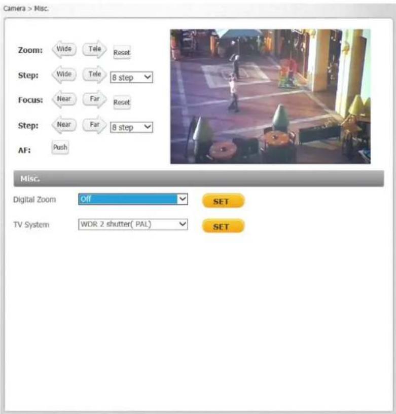
Figure 108: Camera Sengs Screen – Digital Zoom
9.5.5.1 Digital Zoom Sengs
The camera's digital zoom is adjustable from x2 to x10. Select the desired zoom or O.
Click SET to conrm the new seng.
9.5.5.2 TV System Sengs
The TV System opons depend on the model.

Note:
Aer changing the video format, the camera restarts automacally. You must re-enter the unit's IP address again in your browser in order to use the unit with the new sengs.
9.5.5.2.1 CB-6204 TV System Sengs
Select one of two WDR sengs according to your TV standard: WDR 2 shuer (NTSC), WDR 2 shuer (PAL), WDR 3 shuer (NTSC), or WDR 3 shuer (PAL).
The WDR2 shuer seng is composed of one short exposure and one long exposure taken simultaneously and then composited to create the image. The WDR2 shuer seng is recommended for most situations.
The WDR3 shuer seng is composed of three exposures – short, medium, and long – taken simultaneously and then composited to create the image. The WDR3 shuer seng is recommended for more complicated scenes with dicult lighng.
Click SET to conrm the seng.
9.5.5.2.2 CB-6208 TV System Sengs
Select the video system and WDR seng according to the desired frame rate and the TV standard: 25 fps (PAL), 30 fps (NTSC), 50 fps (PAL), or 60 fps (NTSC).
9.6 Log Out
Selecng the Logout link on the Home page to close the session. The following message appears:

Figure 109: Login Message
Upon clicking Login, the Login window opens.

Figure 110: Login Window
10 Appendices
CB-6204 Technical Specicaons
CB-6208 Technical Specicaons
■ Device Search Soware
■ Internet Security Setngs
■ Install UPnP Components
■ Deleng Exisng DVPlayer
■ Deleng Temporary Internet Files
■ Connecng Leads to a Spring Clamp Terminal Block
■ Mounng Accessories
A.1. CB-6204 Technical Specicaons
| Camera | ||
| Image Sensor | 1/3" 2688 x 1520 Progressive Scan BSI CMOS | |
| Eecve Pixels | 2560 x 1440 (H x V) | |
| Shuer Speed | 1.0 to 1/10,000 (auto) | |
| Digital Slow Shuer (DSS) | 1/1 to 1/25 or 1/30 with ≤ 32x sensitivity boost in day/night mode | |
| Sensitivity | 0.3 Lux @F1.4 in color mode; 0.04 Lux @ F1.4 in night mode with IR illuminator ON, measured with DSS OFF at 30 IRE | |
| Enclosure | Tamper-resistant surface mount plasc case | |
| Lens | CB-6204-11-I | CB-6204-21-I |
| Lens Type | Varifocal Motorized P-Iris with auto-focus and True Day/Night | |
| Lens Opons | 3-8mm, F1.4 | 7-22mm, F1.4 |
| Horizontal Viewing Angle | 96-38° | 42-14° |
| Video | ||
| Video Compression | H.264 Main/High Prole (MPEG-4 Part 10), triple-streaming | |
| Video Resoluon | QHD (2560 x 1440)/Full HD 1080p/SXGA (1280 x 1024)/HD 720p/XVGA/SVGA/D1/VGA/CIF/QVGA | |
| Video Streaming (Maximum Performance) | H.264 25/30 fps (PAL/NTSC) @ QHD or simultaneous QHD @ 12/15 fps + HD 720p @ 12/15 fps + D1 @ 12/15 fps (PAL/NTSC) | |
| Rate Control Opon | CBR (64Kbps - 20,480Kbps), VBR | |
| Operaon | ||
| Image Seng | Brightness | Manual |
| Exposure | Auto-iris, Auto/Fixed Shuer | |
| Sharpness | Manual | |
| Contrast | Manual | |
| Hue | Manual | |
| White Balance | Auto/Indoor/Outdoor/ATW/Manual | |
| Gain (AGC) | Automac | |
| Backlight Compensaon | On/O | |
| Digital Zoom | Supported (x2 to x10) | |
| WDR | On/O + 3 levels | |
| 3DNR | On/O + 3 levels (with Latude), On/O + 6 levels (without Latude) | |
| Privacy Mask (Video Mask) | Web interface: On/O. Up to ve embedded web interfaces are supported in the streaming video output, but are not supported by Latude. In the Latude interface, the Privacy Mask is independent of the camera's on-screen display and is not embedded. | |
| IR Funcon | Day/Night (Auto/On/O/Smart) | |
| Audio | Two-way Audio | Line out/Line in |
| Compression | G.711/G.726 (not supported by Latude) | |
| Alarm | Input | 1x 5V 10kΩ pull up dry contact |
| Output | 1x Photo Relay Output 300V DC/AC @ 130mA maximum | |
| Signal-to-Noise Rao | ≥50dB | |
| Event Nocaon | HTTP, FTP, SMTP | |
| Operaon | ||
| Languages | English, German, Spanish, French, Italian, Japanese, Korean, Portuguese, Russian, Simplified Chinese, and Tradional Chinese | |
| Analycs | ||
| Moon Detecon | On/O, plus sampling pixel interval, detecon level, sensitivity level, and me interval sengs. | |
| Regions of Interest | Web interface: Congurable up to 10 ROI masks.Latude interface: Congurable up to six ROI masks. | |
| Moon Metadata | Streaming and recorded video includes per frame level moon metadata. Moon metadata is archive searchable by ROI via the Latude Control Center user interface. | |
| Triggered Acons | Nocaons, On-Event Recording and Relay Output Command.Includes congorable alarms and broad range of recording on detecon of video and snapshots. | |
| Tampering Alarm | On/O, plus duraon, on-event nocaon, recording to SD card, recording to NAS, and more are supported as events in Latude. | |
| IR Illuminator | ||
| Working Distance | 40 meters (131.) at 60° | |
| Wavelength | 850nm | |
| IR Sensitivity | Yes (680-1100nm) | |
| LEDs | 6 | |
| Network | ||
| Interface | 10/100/1000Mbps Ethernet, Auto-sensing, Full/Half-Duplex | |
| Protocols | IPv4/v6, TCP/IP, UDP, RTP, RTSP, HTTP, HTTPS, ICMP, FTP, SMTP, DHCP, PPPoE, UPnP, IGMP, SNMP,SNTP, QoS, IEEE 802.1X, ONVIF Version 2.4 Prole S | |
| Password Levels | User and Administrator | |
| Security | HTTPS, IP Filter, IEEE 802.1x | |
| Firmware Upgrade | Flash memory for upgrade of camera rmware over the network (1GB Flash/8GB RAM) | |
| Operang Systems | Windows XP, 7, 8, and 8.1 | |
| Internet Browser | Internet Explorer (IE 9, 10, and 11) | |
| User Accounts | 20 | |
| Mechanical | ||
| Connectors | Power | 3-pin terminal block |
| Ethernet | RJ45 | |
| Audio | 1x Line-in and 1x Line-out 1.5mm audio jack | |
| Alarm | 4-pin terminal block with 2-pin alarm input and 2-pin relay output | |
| Analog Video | 1.0V p-p/75Ω, BNC (connuously enabled) | |
| LED Indicator | Power, Link, ACT | |
| Enclosure Standards | IP66, NEMA 4, 1K10 vandal-resistant | |
| Mechanical IR Cut Filter | Included | |
| Pan/Rotate/Tilt | 355° pan, ±100° rotate, 80° lt | |
| MicroSDXC Card Recording | Up to 128GB, Class 10 (card not included) | |
| Mounng Adjustment | Full swivel ball joint, 90° lt, 360° rotaon | |
| Physical | ||
| Dimensions (L x W) | 268 x 99 mm (10.55 x 3.89 in.) including mounng ange with mount set to 90°285 x 99 mm (11.22 x 3.89 in.) including mounng ange with mount set to 180° | |
| Weight | 1.07 kg (2.36 lbs.) | |
| Electrical | ||
| Power Consumpon | Indoor | 6W |
| Outdoor | 13W with heater and IR | |
| Power Source | 12VDC (± 10%), 24VAC (± 10%), PoE (802.3af Class 0) | |
| Environmental | ||
| Operang Temperature | -40° to 50°C (-40° to 122°F) with heater-25°C to 50°C (-13° to 122°F) for cold start with POE | |
| Humidity | 10-95% non-condensing | |
| General | ||
| Regulatory | US | FCC 47 CFR Part 15, Subpart B, Class A; UL 60950 |
| Europe | CE (EN 55022-1998 Class A; EN 50130-4; EN 60950); RoHS | |
| Warranty | Four-year limited warranty | |
A.2. CB-6208 Technical Specicaons
| Camera | ||
| Image Sensor | 1/1.7" 4072 x 3076 (12 MP) Progressive Scan BSI CMOS | |
| Eecve Pixels | 3840 x 2160 (H x V) | |
| Shuer Speed | 1.0 to 1/10,000 (auto) | |
| Digital Slow Shuer (DSS) | 1/1 to 1/25 or 1/30 with ≤ 32x sensitivity boost in day/night mode | |
| Sensitivity | 0.3 Lux @F1.4 in color mode; 0.04 Lux @ F1.4 in night mode with IR illuminator ON, measured with DSS OFF at 30 IRE | |
| Enclosure | Tamper-resistant surface mount plasc case | |
| Lens | CB-6208-11-I | |
| Lens Type | Varifocal Motorized F1.4 P-Iris with auto-focus and True Day/Night | |
| Lens Opons | 3.5-8mm | |
| Horizontal Viewing Angle | 116-50° | |
| Video | ||
| Video Compression | H.264 and MJPEG | |
| Video Resoluon | UHD 4K (3840 x 2160)/Full HD 1080p/SXGA (1280 x 1024)/HD 720p/XVGA/SVGA/D1/VGA/CIF/QVGA | |
| Video Streaming(Maximum Performance) | H.264 25/30 fps (PAL/NTSC) @ 4K or simultaneous 4K @ 12/15 fps + Full HD 1080p @ 12/15 fps + HD 720p @ 12/15 fps + D1 @ 12/15 fps (PAL/NTSC) | |
| Rate Control Opon | CBR (64Kbps - 20,480Kbps), VBR | |
| Operaon | ||
| Image Seng | Brightness | Manual |
| Exposure | Auto-iris, Auto/Fixed Shuer | |
| Sharpness | Manual | |
| Contrast | Manual | |
| Hue | Manual | |
| White Balance | Auto/Indoor/Outdoor/ATW/Manual | |
| Gain (AGC) | Automac | |
| Backlight Compensaon | On/O | |
| Digital Zoom | Supported (x2 to x10) | |
| WDR | On/O + 3 levels | |
| 3DNR | On/O + 3 levels (with Latude), On/O + 6 levels (without Latude) | |
| Privacy Mask(Video Mask) | Web interface: On/O. Up to ve embedded web interfaces are supported in the streaming video output, but are not supported by Latude. In the Latude interface, the Privacy Mask is independent of the camera's on-screen display and is not embedded. | |
| IR Funcon | Day/Night (Auto/On/O/Smart) | |
| Audio | Two-way Audio | Line out/Line in |
| Compression | G.711/G.726 (not supported by Latude) | |
| Alarm | Input | 1x 5V 10kΩ pull up dry contact |
| Output | 1x Photo Relay Output 300V DC/AC @ 130mA maximum | |
| Signal-to-Noise Rao | ±50dB | |
| Event Nocaon | HTTP, FTP, SMTP | |
| Operaon | ||
| Languages | English, German, Spanish, French, Italian, Japanese, Korean, Portuguese, Russian, Simplied Chinese, and Tradional Chinese | |
| Analycs | ||
| Moon Detecon | On/O, plus sampling pixel interval, detecon level, sensitivity level, and me interval sengs. | |
| Regions of Interest | Web interface: Congurable up to 10 ROI masks.Latude interface: Congurable up to six ROI masks. | |
| Moon Metadata | Streaming and recorded video includes per frame level moon metadata. Moon metadata is archive searchable by ROI via the Latude Control Center user interface. | |
| Triggered Acons | Nocaons, On-Event Recording and Relay Output Command.Includes congorable alarms and broad range of recording on detecon of video and snapshots. | |
| Tampering Alarm | On/O, plus duraon, on-event nocaon, recording to SD card, recording to NAS, and more are supported as events in Latude. | |
| IR Illuminator | ||
| Working Distance | 40 meters (131.) at 60° | |
| Wavelength | 850nm | |
| LEDs | 6 | |
| Network | ||
| Interface | 10/100/1000Mbps Ethernet, Auto-sensing, Full/Half-Duplex | |
| Protocols | IPv4/v6, TCP/IP, UDP, RTP, RTSP, HTTP, HTTPS, ICMP, FTP, SMTP, DHCP, PPPoE, UPnP, IGMP, SNMP,SNTP, QoS, IEEE 802.1X, ONVIF Version 2.4 Prole S | |
| Password Levels | User and Administrator | |
| Security | HTTPS, IP Filter, IEEE 802.1x | |
| Firmware Upgrade | Flash memory for upgrade of camera rmware over the network (1GB Flash/8GB RAM) | |
| Operang Systems | Windows XP, 7, 8, and 8.1 | |
| Internet Browser | Internet Explorer (IE 9, 10, and 11) | |
| User Accounts | 20 | |
| Mechanical | ||
| Connectors | Power | 3-pin terminal block |
| Ethernet | RJ45 | |
| Audio | 1x Line-in and 1x Line-out 1.5mm audio jack | |
| Alarm | 4-pin terminal block with 2-pin alarm input and 2-pin relay output | |
| Analog Video | 1.0V p-p/75Ω, BNC (connuously enabled) | |
| LED Indicator | Power, Link, ACT | |
| Weatherproof Standard | IP66 | |
| Mechanical IR Cut Filter | Included | |
| Pan/Rotate/Tilt | 355° pan, ±100° rotate, 80° lt | |
| MicroSDXC Card Recording | Up to 128GB, Class 10 microSDXC card (card not included) | |
| Physical | ||
| Dimensions (L x W) | 218 x 99 mm (8.59 x 3.89 in.) | |
| Weight | 0.98 kg (34.5 oz.) | |
| Electrical | ||
| Power Consumpon | Indoor | 6W |
| Outdoor | 13W with heater and IR | |
| Power Source | 12VDC (± 10%), 24VAC (± 10%), PoE (802.3af Class 0) | |
| Environmental | ||
| Operang Temperature | -40° to 50°C (-40° to 122°F) with heater-25°C to 50°C (-13° to 122°F) for cold start with POE | |
| Humidity | 10-95% non-condensing | |
| General | ||
| Regulatory | US | FCC 47 CFR Part 15, Subpart B, Class A; UL 60950 |
| Europe | CE (EN 55022-1998 Class A; EN 50130-4; EN 60950) RoHS | |
| Warranty | Four-year limited warranty | |
A.3. Internet Security Sengs
If AcveX control installaon is blocked, either set Internet security level to default or change AcveX controls and plug-in sengs.
To set the default Internet security level
- Start Internet Explorer (IE).
- From the Command Bar toolbar, select Tools and select Internet Opons from the menu that appears.
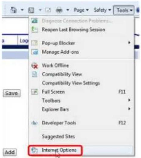
Figure 111: Command Bar Toolbar – Select Internet Opons
- In the Internet Opons window that appears, select the Security tab.
- Select Internet in Select a zone to view or change security sengs.
- If the sengs are not dened as default, select Default Level and move the Allowed levels for this zone slider to Medium-high and select OK.
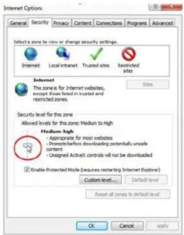
Figure 112: Internet Opons Screen
- Close all browsers and reopen so that the sengs take eect.
AcveX Controls and Plug-in Sengs
To create a custom level
- Start Internet Explorer (IE).
- From the Command Bar toolbar, select Tools and select Internet Opons from the menu that appears.
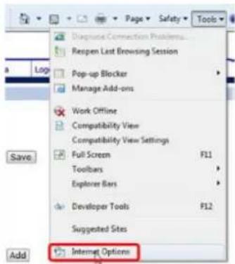
Figure 113: Command Bar Toolbar – Internet Opons
- In the Internet Opons window that appears, select the Security tab.
- If not already selected, select Internet, then select Custom Level.
- In the dialog that appears, under AcveX controls and plug-ins set ALL the following opons (listed below) to Enable or Prompt:
■ Automac prompting for AcveX controls
■ Binary and script behaviors
■ Download signed AcveX controls
■ Download using AcveX controls
■ Initialize and script AcveX not marked as safe
■ Run AcveX controls and plug-ins
- Script AcveX controls marked safe for scripng

Figure 114: Schedule Screen
- Click OK to accept the sengs and close the Security screen.
- Click OK to close the Internet Opons screen.
- Close the browser window and restart IE again to access the camera.
A.4. Install UPnP Components
Follow the instrucons below to enable UPnP so that the camera can be discovered and displayed in Network locaons under Other Devices:

To enable UPnP discovery in Windows 7, 8, and 8.1
- Click (Start) and select Control Panel.
- Click Network and Internet.
(Start) and select Control Panel.


- Click Network and Sharing Center.

Network and Sharing Center
View network status and tasks
Connect to a network
View network computers and devices
Add a wireless device to the network
- Click Change advanced sharing settings.
Control Panel Home
Change adapter settings
Change advanced sharing settings
- Expand the Home or Work node, select Turn on network discovery.

- Click Save Changes.

Note:
Network discovery requires that the DNS Client, Funcon Discovery Resource Publicaon, SSDP Discovery, and UPnP Device Host services are started, that network discovery is allowed to communicate through Windows Firewall, and that other rewalls are not interfering with network discovery.
To check that the UPnP Device Host services are running
- Click (Start) and type in the Search programs and les eld services.msc and then select services.msc from the displayed Programs. The Services manager dialog box appears.
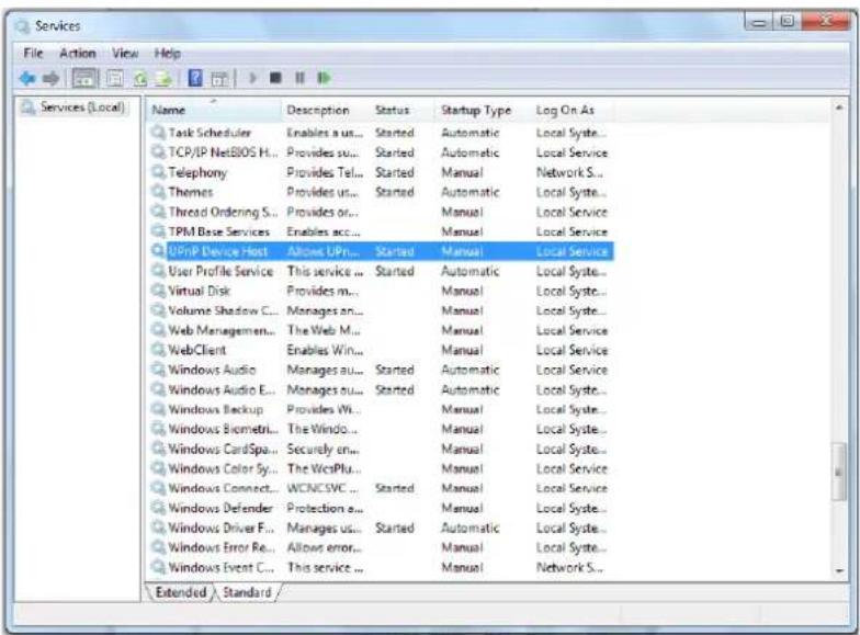
- In the Services manager dialog box, scroll down the list to UPnP Device Host and verify that it shows the status Started. If Started is not displayed, right-click and select Start from the shortcut menu.
A.5. Deleng the Exisng DVPlayer
Users who have previously installed the DVPlayer in the PC should rst delete the exisng DVPlayer from the PC before accessing the camera.
To delete a legacy DVPlayer

-
Click Start and select Control Panel.
-
In the Control Panel, click Uninstall a program.

-
From the installed program list, select DVPlayer and then, on the banner bar, click Uninstall.
-
If prompted to conrm the Uninstall, click Yes.
A.6. Deleng Temporary Internet Files
To improve browser performance, it is recommended to clean up all of the temporary Internet les.
To delete temporary Internet les
- In Internet Explorer (IE), from the Command Bar toolbar, click Tools and select Internet Opons from the menu that appears.

- In the General tab in the Internet Opons dialog box, click Delete.
- In the Delete Browser History dialog box that appears, select Temporary Internet les. Deselect Cookies and History to keep this data. Then click Delete.

A.7. Mounng Accessories
The following moung accessories are available from DVTEL for installaon of your Quasar Gen II CB-6204 Series Bullet IP Camera. For more informaon on available opons, contact your DVTEL sales representave or visit www.DVTEL.com to request details on where to get the accessories you need.
| Image | Name | Descripon |
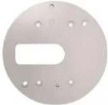 | CB-4S-62 | 4S Electrical Box Mounng Adapter |
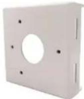 | CB-POLE-62 | Pole Mount |
Contacng DVTEL
DVTEL Inc. is a mulple award-winning market leader in the development and delivery of intelligent security soluons over IP networks. DVTEL provides unied soluons that leverage exisng network infrastructure, while providing unmatched levels of exibility, scalability and cost-eeciveness - all backed by superior customer support.
To contact us, write us at info@DVTEL.com, or contact your local oce.
| CORPORATE HEADQUARTERSDVTEL, Inc.65 Challenger RoadRidgeeld Park, NJ 07660USATel: +1 201.368.9700Fax: +1 201.368.2612info@DVTEL.com | ASIA PACIFIC REGIONDVTEL111 North Bridge Road, #27-01Peninsula PlazaSingapore 179098Tel: +65 6389 1812Fax: +65 6491 5660info.apac@DVTEL.com |
| ANZ AND THE PACIFIC ISLANDSDVTEL37 Victoria StreetHenley Beach, SA 5022AustraliaTel: +61 8 8235 9211Fax: +61 8 8235 9255info.anz@DVTEL.com | EMEADVTEL UK Ltd.7 Lancaster CourtCoronaon RoadHigh WycombeHP12 3TD EnglandTel: +44 (0) 1494 412240Fax: +44 (0) 1494 446928info.uk@DVTEL.com |
| INDIA AND SAARC, GULF REGIONDVTEL, India Pvt., Ltd123 SSR Corporate ParkMathura RoadFaridabad 121002Haryana, IndiaTel: +91 (129) 431 5031Fax: +91 (129) 431 5033info.asia@DVTEL.com | CENTRAL AND LATIN AMERICADVTEL Mexico S.A.P.I. de C.V.Felipe Villanueva No. 10Col. Guadalupe InnMéxico D. F. 01020MéxicoTel: +52 55 5580 5618Fax: +52 55 8503 4299info.cala@DVTEL.com |
| DVTEL NORTH ASIA2404, 24/F, World-Wide House19 Des Voeux Road CentralHong KongTel: +852 3667 9295Mobile: +852 9479 4195info.northasia@DVTEL.com | DVTEL 中国北京朝阳区西大望路甲1号温特莱中心B座12层09单元100026电话: +86-10-8586-8836手机: +86-13501266857传真: +86-10-8586-8812邮箱:info.china@DVTEL.com |
To request the latest versions of rmware and soware or to download other product-related documents, visit hp://www.DVTEL.com/support. If you have obtained a login, go to our support gateway. For assistance, email us at support@DVTEL.com or phone 1-888-DVTEL77.
- Quasar
- Quasar CB-6204 Quasar CB-6208 IP Bullet Camera User and Installaon Guide
- Table of Contents
- Appendices....121
- Contacng DVTEL....135
- List of Figures
- Document Informaon
- Document Conventions
- Conventions relatives au document
- Document Scope and Purpose
- Note:
- Remarque:
- Averssement:
- Proprietary Rights and Non-Disclosure
- Trademarks and Copyrights
- Disclaimer
- General Cautions and Warnings
- SAVE ALL SAFETY AND OPERATING INSTRUCTIONS FOR FUTURE USE.
- Aenon:
- Electrical Safety Notice and Warnings
- Warning:
- Minimizing EMI and RFI
- Overview
- Cauon:
- Package Contents
- Related Documentaon
- Introducon to the CB-620x IP Bullet Camera
- Typical CB-620x Camera
- Camera Dimensions
- Internal Connectors
- To perform a hard reset to full factory defaults using the Reset buon
- System Cable Connectors
- Waterproong the Camera Cable Connectors
- To waterproof the system cable
- RJ45 Cable
- To waterproof the RJ45 cable
- IP66-Rated RJ45 Cable
- To waterproof the IP66-Rated RJ45 cable
- Connecng the Unit to the Network
- Connecng Power to the Camera
- Input and Output Connectors
- System Requirements
- Installaon
- Related Links
- Indoor Installaon
- Outdoor Installaon
- Power and Ethernet Cable Connecon
- Inial Camera Conguraon
- To perform the initial camera conguraon
- Tip:
- Mounng Instrucons
- Eliminang IR Reecon
- To eliminate IR reecon
- Mounng the Camera
- Installing the Camera
- To install the camera
- Using the DNA Utility to Search and Access the Camera
- Conguring Communicaon Setngs on the Quasar Camera
- To congure communicaon sengs on the camera
- Adjusting and Framing-Up the Camera View
- To adjust and frame-up the camera view
- Conguraon and Operaon
- Browser-Based Viewer Introducon
- Live Buon
- ■ Sengs Buon
- - System Sengs
- - Streaming Sengs
- - Camera Sengs
- Live Screen
- Snapshot
- Record/Pause
- Video Streaming Restart/Stop
- Mic
- Manual Trigger
- Speaker
- Zoom: Wide/Tele
- Zoom Reset
- Step: Wide/Tele
- Step Range
- Focus: Near/Far
- Focus Reset
- Step: Near/Far
- AF: Push
- System Sengs
- System
- Host Name
- Time Zone
- Enable Daylight Saving Time
- Time format
- Sync with Computer Time
- Manual
- Sync with NTP Server
- Security
- User
- Admin Password
- Add user
- To add a new user
- Click Add.
- Manage User
- Streaming Authencaon Seng
- HTTPS
- To create a self-signed cercate
- To create a cercate request
- IP Filter
- To enable the IP Iter
- To add or delete an IP address
- IEEE 802.1X
- CA Cercate
- Client Cercate
- Private Key
- Sengs
- Enable IEEE 802.1X
- Network
- Basic
- General
- To set up a new stac IP address
- To use PPPoE
- Advanced
- IPv6 Address Conguraon
- QoS
- DSCP Sengs
- SNMP Sengs
- SNMP v1/v2
- SNMP v3
- Traps for SNMP v1/v2/v3
- UPnP
- UPnP Sengs
- DDNS
- To use DDNS
- FTP
- HTTP
- Events Setup
- IO
- Alarm Output
- Follow these steps:
- File Name
- Network Failure Detecon
- Detecon Type
- Triggered Acon
- Tampering
- Tampering Alarm
- Tampering Duraon
- Tampering Acon
- File Name
- ■ Overwrite
- Day/Night Trigger
- Periodic Event
- Periodic Event
- Time Interval
- Triggered Acon
- File Name
- Manual Trigger
- Manual Trigger
- Triggered Acon
- File Name
- SD Card
- Device Informaon
- Device Seng
- Disk Cleanup Seng
- Recording List
- Network Share
- Storage Tools
- Recording
- To set the recording schedule
- Moon Detecon
- Moon Detecon Acvaon
- To set a schedule
- Moon Detecon Windows
- Triggered Acon
- File Name
- Schedule
- To create a new schedule or edit an existing schedule
- To remove a schedule
- File Locaon
- Maintenance
- Log File
- User Informaon
- View User Login Informaon
- View User Privilege
- Factory Default
- Full Restore
- Paral Restore
- Reboot
- Soware Version
- Soware Upgrade
- To upgrade the soware
- Export
- Video Format
- CB-6204 Video Resoluon Sengs
- MJPEG-Only
- H.264 + H.264 and H.264 + MJPEG
- H.264 + H.264 + H.264 and H.264 + H.264 + MJPEG
- CB-6208 Video Resoluon Sengs
- H.264 + H.264 and H.264 + MJPEG
- Text Overlay Sengs
- Video Rotate Type
- GOV Sengs
- H.264 Prole
- - Baseline Prole (BP)
- - Main Prole (MP)
- • High Prole (HP)
- Video Compression
- MJPEG Compression Seng
- H.264 Compression Seng
- CBR Mode Seng
- Video ROI Encoding
- To use ROI encoding
- Video OCX Protocol
- Video Frame Rate
- MJPEG/H.264 Frame Rate Seng
- Video Mask
- Acve Mask Funcon
- To enable a mask
- To disable a mask
- Mask Seng
- Audio
- Transmission Mode
- Server Gain Seng
- Bit Rate
- Recording to Storage
- Camera Sengs
- Exposure
- CB-6204 Exposure Screen
- P-Iris Priority Mode
- Auto P-Iris Mode
- Manual Mode
- CB-6208 Exposure Screen
- Auto Mode
- Manual Mode (Fixed Shuer)
- Gain
- Picture Adjustment
- Brightness
- Sharpness
- Contrast
- Saturaon
- Hue
- Advanced Picture Sengs
- White Balance
- Backlight
- WDR Funcon and Shuer WDR
- Noise Reducon
- IR Funcon
- IR Mode
- IR LED Illuminator
- Day/Night Threshold
- IR Compensaon
- Miscellaneous
- Digital Zoom Sengs
- TV System Sengs
- CB-6204 TV System Sengs
- CB-6208 TV System Sengs
- Log Out
- Appendices
- A.1. CB-6204 Technical Specicaons
- A.2. CB-6208 Technical Specicaons
- A.3. Internet Security Sengs
- To set the default Internet security level
- AcveX Controls and Plug-in Sengs
- To create a custom level
- A.4. Install UPnP Components
- To enable UPnP discovery in Windows 7, 8, and 8.1
- To check that the UPnP Device Host services are running
- A.5. Deleng the Exisng DVPlayer
- To delete a legacy DVPlayer
- A.6. Deleng Temporary Internet Files
- To delete temporary Internet les
- A.7. Mounng Accessories
- Contacng DVTEL
Brand : FLIR
Model : Quasar CB-6204
Category : Security Camera