
DL-HD70LSIR - AV Extender Digitalinx - Free user manual and instructions
Find the device manual for free DL-HD70LSIR Digitalinx in PDF.


| Product Type | AV Extender (HDMI over HDBaseT) |
| Model | DL-HD70LSIR |
| Brand | Digitalinx |
| Maximum Transmission Distance | 70 meters (230 ft) via CAT6/6a cable |
| Supported Video Resolution | Up to 4K@60Hz 4:4:4 |
| HDMI Version | HDMI 2.0 with HDCP 2.2 |
| Audio Support | Pass-through for LPCM 7.1, Dolby TrueHD, DTS-HD Master Audio |
| Ethernet Pass-Through | RJ45 100Base-TX |
| IR Control | IR pass-through (bidirectional) |
| Power Supply | DC 5V / 2A (included adapter) |
| Power Consumption | Transmitter: 2.5W, Receiver: 3.5W (max) |
| Dimensions (Transmitter) | 100 x 65 x 25 mm |
| Dimensions (Receiver) | 100 x 65 x 25 mm |
| Weight (Transmitter) | 120 g |
| Weight (Receiver) | 120 g |
| Operating Temperature | 0°C to 50°C (32°F to 122°F) |
| Housing Material | Metal (aluminum alloy) |
| LED Indicators | Power, Link, Video signal |
| Installation | Plug-and-play, no software required |
| Included Accessories | 2x IR emitter cable, 1x IR receiver cable, power adapters, mounting brackets |
| Certifications | CE, FCC, RoHS |
Frequently Asked Questions - DL-HD70LSIR Digitalinx
User questions about DL-HD70LSIR Digitalinx
0 question about this device. Answer the ones you know or ask your own.
Ask a new question about this device
Download the instructions for your AV Extender in PDF format for free! Find your manual DL-HD70LSIR - Digitalinx and take your electronic device back in hand. On this page are published all the documents necessary for the use of your device. DL-HD70LSIR by Digitalinx.
USER MANUAL DL-HD70LSIR Digitalinx
DL-HD70LSIR Owners Manual

Important Safety Instructions
» Please completely read and verify you understand all instructions in this manual before operating this equipment.
» Keep these instructions in a safe, accessible place for future reference.
»Heed all warnings.
»Follow all instructions.
»Do not use this apparatus near water.
»Clean only with a dry cloth.
» Do not install near any heat sources such as radiators, heat registers, stoves, or other apparatus (including amplifiers) that produce heat.
»Use only accessories specified or recommended by Intelix.
»Explanation of graphical symbols:
Lightning bolt/flash symbol: the lightning bolt/flash and arrowhead within an equilateral triangle symbol is intended to alert the user to the presence of uninsulated "dangerous voltage" within the product enclosure which may be of sufficient magnitude to constitute a risk of shock to a person or persons.
Exclamation point symbol: the exclamation point within an equilateral triangle symbol is intended to alert the user to the presence of important operating and maintenance (servicing) instructions in the literature accompanying the product.

» WARNING: TO REDUCE THE RISK OF FIRE OR ELECTRIC SHOCK, DO NOT EXPOSE THIS APPARATUS TO RAIN OR MOISTURE AND OBJECTS FILLED WITH LIQUIDS, SUCH AS VASES, SHOULD NOT BE PLACED ON THIS APPARATUS.
»Use the mains plug to disconnect the apparatus from the mains.
»THE MAINS PLUG OF THE POWER CORD MUST REMAIN READILY ACCESSIBLE.
» Do not defeat the safety purpose polarized or grounding-type plug. A polarized plug has two blades with one wider than the other. A grounding-type plug has two blades and a third grounding prong. The wide blade or the third prong is provided for your safety. If the provided plug does not fit into your outlet, consult an electrician for replacement of your obsolete outlet. Caution! To reduce the risk of electrical shock, grounding of the center pin of this plug must be maintained.
» Protect the power cord from being walked on or pinched particularly at the plugs, convenience receptacles, and the point where they exit from the apparatus.
» Do not block the air ventilation openings. Only mount the equipment per Intelix's instructions.
» Use only with the cart, stand, table, or rack specified by Intelix or sold with the equipment. When/if a cart is used, use caution when moving the cart/equipment combination to avoid injury from tip-over.
» Unplug this apparatus during lightning storms or when unused for long periods of time.
» Caution! Shock Hazard. Do not open the unit.
» Refer to qualified service personnel. Servicing is required when the apparatus has been damaged in any way, such as power supply cord or plug is damaged, liquid has been spilled or objects have fallen into the apparatus, the apparatus has been exposed to rain or moisture, does not operate normally, or has been dropped.

Table of Contents
Product Overview....4
Package Contents 4
Front and Rear Panels.... 5
Transmitter / Receiver View 5
Installation Instructions....6
Quick Start 6
Connecting a Video Source 6
HDMI Input (Transmitter) 6
Connecting a Display....6
HDMI Output (Receiver) 6
HDBaseT Connection....7
Connecting IR Control 8
Source Device Control using IR....8
Remote Display using IR 8
Source / Display Control from Control System 8
Apply Power 9
Application Diagrams.... 10
HDMI Extension / Bi-Directional IR Control....10
HDMI Extension / Control System IR Control....11
Technical Specifications 12
Product Overview
The DigitaLinx DL-HD70LSIR extender set transmits HDMI audio and video, up to 4K@60Hz 4:2:0 / 8 bit color, and bidirectional IR up to 70 meters away using a single solid core, shielded Category 6 twisted pair cable. The extender set support HDCP versions up to 2.2. With its slim design the DL-HD70LSIR is easy to install in the tightest of spaces.
Built-in surge protection helps ensure hassle-free and robust installations. The 18 volt power supply is secured with a screw-on connector to prevent the power from being accidentally disconnected.
The DL-HD70LSIR is sold only as a set. The individual transmitter and receiver are not compatible with other HDBaseT devices due to proprietary PoE circuitry.
Package Contents
• DL-HD70LSIR Extender Set
- Quick Install Guide
• (1) IR Emitter
• (1) IR Broadband Receiver (30-50KHz)
• (1) DC18V 1A power supply with US, UK, EU and AU power adapter plugs
• (4) Mounting clips with mounting screws
• (1) IR-AC IR coupler cable
Front and Rear Panels
Transmitter / Receiver View

- DC 18V - Locking power supply port (transmitter)
- HDBT OUT - HDBaseT output; RJ45 connection
- IR IN - 3.5mm IR input port for connection to IR receiver or 3rd party IR system
- IR OUT - 3.5mm IR output port for connection to IR emitter
- HDMI IN - HDMI input port for connection to HDMI video source
- DC 18V - Locking power supply port (receiver)
- HDBT OUT - HDBaseT input; RJ45 connection
- IR IN - 3.5mm IR input port for connection to IR receiver or 3rd party IR system
- IR OUT - 3.5mm IR output port for connection to IR emitter
- HDMI OUT - HDMI output port for connection to display
Front Panel LED States for Transmitter / Receiver
POWER (RED) - Solid when device is powered ON
STATUS (BLUE) - When blinking the device is working properly
HDCP (BLUE) - Solid when HDMI signal is encrypted; blinking when non-HDCP protected content is transmitted; OFF when no content is being transmitted
LINK (GREEN) - Solid when successful link between transmitter and receiver is established; off or blinking indicates a physical link error
Installation Instructions
Quick Start
- Connect video source to transmitter HDMI IN
- Connect display technology to receiver HDMI OUT
- Connect transmitter and receiver together with a shielded Category 6 cable
- Connect IR control (optional)
- Apply power to either transmitter OR receiver to power entire circuit
Connecting a Video Source
HDMI Input (Transmitter)
Connect an HDMI source device to the HDMI input on the DL-HD70LSIR transmitter labeled HDMI IN using an HDMI cable that is less than or equal to 5 meters in total length. For HDMI source devices that are further away, an active HDMI cable may be required to complete the connection.
Connecting a Display
HDMI Output (Receiver)
Connect the display to the HDMI output on the DL-HD70LSIR receiver labeled HDMI OUT using an HDMI cable that is less than or equal to 5 meters in length. It is recommended to keep the DL-HD70LSIR receiver near the display input as it is not recommended that an active HDMI cable be used on the HDMI output on the DL-HD70LSIR receiver.
HDBaseT Connection
Connect one end of a Category cable to the DL-HD70LSIR transmitter labeled TWISTED PAIR, then connect the other end of the Category cable to the DL-HD70LSIR receiver labeled TWISTED PAIR
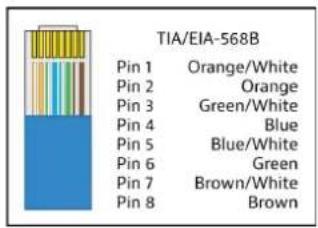
Twisted Pair Wiring
Use TIA/EIA-568B wiring for Category 6 connection between send and receive units.
To ensure proper performance of the DL-HD70LSIR, it is recommended that you use solid core, shielded Category 6 F/UTP cabling at a minimum. Category 5e F/UTP may perform well up to a certain length but may not support power over HDBaseT reliably longer distances.

When using shielded category cabling ALWAYS...
.....use shielded connectors
....properly ground the category cable
For optimized performance use the following Liberty Wire and Cable branded cabling;
Category 6 plenum; 24-4P-P-L6SH
Category 6A plenum; 24-4P-P-L6ASH
Category 6 NON-plenum; 24-4P-L6SH
Category 6A NON -plenum; 24-4P-L6ASH
Connecting IR Control
The DL-HD70LSIR is capable of transmitting bi-directional IR signals through the HDBaseT circuit. The DL-HD70LSIR comes with an IR receiver (eye) and an IR emitter (flasher) so you can control devices from either end of the extender circuit.

Passing IR Signals:
The DL-HD70LSIR is capable of passing IR signals between 33 and 55 KHz. To prevent damage to any of the electronics, the extenders should be powered off while inserting or removing any IR components. Inserting an IR transmitter into the IR IN port may damage the IR circuit for that extender.
Source Device Control using IR
Attach the IR emitter to the IR receiver of the source device, insert the TS 3.5 mm plug of the emitter to the IR OUT port of the DL-HD70LSIR transmitter. Insert the TS 3.5 mm plug of the IR receiver (eye) to the IR IN port of the DL-HD70LSIR receiver. Point the source device IR remote at the display location where the IR receiver is located, IR signals will now travel through HDBaseT to the DL-HD70LSIR transmitter side where the IR emitter is attached to the source device.
Remote Display using IR
Attach the IR emitter to the IR receiver of the display device, insert the TS 3.5 mm plug of the emitter to the IR OUT port of the DL-HD70LSIR receiver. Insert the TS 3.5 mm plug of the IR receiver (eye) to the IR IN port of the DL-HD70LSIR transmitter. Point the source device IR remote at the source device location where the IR receiver is located, IR signals will now travel through HDBaseT to the DL-HD70LSIR receiver side where the IR emitter is attached to the display device.
Source / Display Control from Control System
To pass 3rd party IR system signals through the DL-HD70LSIR, such as a control system, connect the TS connector of the IR-AC coupling cable (provided) to the IR output port of the control system and connect the TRS connector of the IR-AC cable to the IR IN to either transmitter or receiver of the DL-HD70LSIR.

Apply Power
Connect the included power supply to the transmitter or receiver and lock the power supply to the power connector by twisting the locking collar clockwise. It is not required that both the transmitter and receiver be powered simultaneously.
Application Diagrams
HDMI Extension / Bi-Directional IR Control

flowchart
graph TD
    A["Display Remote"] --> B["Media Player"]
    B --> C["HDMI IN"]
    C --> D["DL-HD70LSIR HDI/SIR Extender"]
    D --> E["HDBI OUT"]
    E --> F["DC 16V"]
    F --> G["IR IN"]
    G --> H["IR OUT"]
    H --> I["HDMI IN"]
    J["Media Player Remote"] --> K["HDMI"]
    K --> L["DL-HD70LSIR HDI/SIR Extender"]
    L --> M["DC 16V"]
    M --> N["IR IN"]
    N --> O["IR OUT"]
    O --> P["HDMI IN"]
    Q["Display"] --> R["Media Player Remote"]
    R --> S["HDMI"]
    S --> T["ATx"]
    T --> U["IR"]
    U --> V["HDMI IN"]
HDMI Extension / Control System IR Control

flowchart
graph TD
    A["Control System"] --> B["IR-AC Cable (provided)"]
    B --> C["DL-HD70LSIR HDI-HEASET with Extension Transmitter"]
    C --> D["DC 16V HDBT OUT IR IN IR OUT HDMI IN"]
    D --> E["HDBT™"]
    E --> F["up to 70m / 230'"]
    F --> G["DL-HD70LSIR HDI-HEASET with Extended Transmitter"]
    G --> H["DC 16V HDBT OUT IR IN IR OUT HDMI IN"]
    H --> I["IR Emitter"]
    I --> J["Display"]
Technical Specifications
| Supported Audio and Video | |
| Video Compliance HDMI 2.0+, HDCP2.2 | |
| Input / Output Resolution Support | SMPTE: Up to 4096x2160@60Hz (4:2:0 chroma sub-sampling / 8 bit deep color)VESA: Up to 1920x1200 |
| Maximum Pixel Clock 340MHz | |
| Embedded Audio Up to PCM 8 channel, Dolby Digital TrueHD, and DTS-HD Master Audio | |
| IR Carrier Frequency Range 33-50kHz at 5 volts | |
| HDBaseT Signal Characteristics | |
| Maximum Distance 1080p: 70 meters / 231 feet4K@60Hz 4:2:0: 40 meters / 132 feet | |
| Cable Requirements Solid core shielded Category 6 F/UTP or greater with TIA/EIA-568B crimp pattern | |
| Bandwidth 10.2 Gbps | |
| Chassis and Environmental | |
| Dimensions (H x W x D) 15 mm x 109 mm x 64 mm (.59 in x 4.29 in x 2.52 in) | |
| Product Weight .18kg / 0.4lbs for each transmitter / receiver | |
| Operating Temperature 0° to +45°C (+32° to +113°F) | |
| Storage Temperature -20°C to 70°C (-4°F to 158°F) | |
| Operating Humidity (Environment) | 10% to 90%, Non-condensing |
| ESD Protection | Human-body Model:±8kV (Air-gap discharge)±4kV (Contact discharge) |
| Surge Protection | Voltage: ±1 kV |
| Power | |
| Maximum Power Consumption | 8.8 watts |
| Power Supply Input Voltage | 100-240V AC at 50-60 Hz |
| Power Supply Output Voltage | 18V DC |
| Regulatory | CE, FCC, RoHS |
| Other | |
| Standard Warranty | 5 Years |
| Included Items | Quick Guide, Power Supply, Adapter Plugs (US, EU, AU, UK), (4) Mounting Brackets, (4) Mounting Screws, (1) IR-AC IR adapter cable (1) IR Emitter and (1) IR Receiver |
Distances and picture quality may be affected by cable grade, cable quality, source and destination equipment, RF and electrical interference, and cable patches.
Thank you for your purchase.
For Technical Support please call our toll free number at 800-530-8898 or email us at supportlibav@libav.com
www.libav.com

DIGITALINX
VALUE-ENGINEERED DIGITAL SOLUTIONS
is a brand of:

LIBERTY®
AV SOLUTIONS
A SUBSIDIARY OF WESCO DISTRIBUTION, INC.
11675 Ridgeline Drive
Colorado Springs, Colorado
80921 USA
Phone: 719-260-0061
Fax: 719-260-0075
Toll-Free: 800-530-8998

- DL-HD70LSIR Owners Manual
- Important Safety Instructions
- Table of Contents
- Product Overview
- Package Contents
- Front and Rear Panels
- Front Panel LED States for Transmitter / Receiver
- Installation Instructions
- Quick Start
- HDMI Input (Transmitter)
- HDMI Output (Receiver)
- HDBaseT Connection
- Connecting IR Control
- Passing IR Signals:
- Source Device Control using IR
- Remote Display using IR
- Source / Display Control from Control System
- Apply Power
- Application Diagrams
- DIGITALINX
- VALUE-ENGINEERED DIGITAL SOLUTIONS
- LIBERTY®
- AV SOLUTIONS
Brand : Digitalinx
Model : DL-HD70LSIR
Category : AV Extender