
airFiber 11FX AF-11FX - Wi-Fi repeater Ubiquiti Networks - Free user manual and instructions
Find the device manual for free airFiber 11FX AF-11FX Ubiquiti Networks in PDF.


| Product Type | Licensed Backhaul Radio (11 GHz FDD) |
| Model | AF-11FX |
| Dimensions | 327 x 112 x 86 mm (12.87 x 4.41 x 3.39 in) |
| Weight | 2.26 kg (5.0 lb) |
| Power Supply | 50V, 1.2A PoE Gigabit Adapter (included) or DC Power Block (38-56VDC) |
| Power Method | Passive Power over Ethernet or DC Power Block |
| Networking Interfaces | 1x 10/100/1000 Data Port (PoE), 1x 10/100 Management Port |
| Wireless Modes | SISO / MIMO |
| Frequency Range | 10.7 – 11.7 GHz |
| Channel Bandwidth | Selectable: 3.5, 5, 7, 10, 14, 20, 28, 30, 40, 50, 56 MHz |
| Maximum Throughput | 1.2+ Gbps |
| Maximum Range | 300+ km |
| Encryption | 128-bit AES (always on) |
| Duplexer | Low-Band (AF-11FX-DUP-L) or High-Band (AF-11FX-DUP-H) included; optional second for MIMO |
| Operating Temperature | -40 to 55°C (-40 to 131°F) |
| Certifications | FCC Part 101, ETSI EN 302 217 |
| Mounting | Compatible with airFiber X antenna AF-11G35 |
| Package Contents | AF-11FX radio, duplexer, PoE adapter, quick start guide, mounting hardware |
| Safety | Professional installation required; use shielded Ethernet; ground wire mandatory |
| Maintenance | Keep clean and dry; avoid use during electrical storms; use only supplied accessories |
| Repair / Spare Parts | Duplexer models AF-11FX-DUP-L/H; antenna AF-11G35; power adapter GP-C500-120G |
Frequently Asked Questions - airFiber 11FX AF-11FX Ubiquiti Networks
User questions about airFiber 11FX AF-11FX Ubiquiti Networks
0 question about this device. Answer the ones you know or ask your own.
Ask a new question about this device
Download the instructions for your Wi-Fi repeater in PDF format for free! Find your manual airFiber 11FX AF-11FX - Ubiquiti Networks and take your electronic device back in hand. On this page are published all the documents necessary for the use of your device. airFiber 11FX AF-11FX by Ubiquiti Networks.
USER MANUAL airFiber 11FX AF-11FX Ubiquiti Networks
airFiber® 11FX
11 GHz FDD
Licensed Backhaul Radio
Model: AF-11FX
USER GUIDE
Table of Contents
Chapter 1: Overview....1
Introduction....1
Package Contents ....1
airFiber Configuration Interface System Requirements ....1
Hardware Overview ....1
Chapter 2: Installation ....5
Installation Requirements ....5
Installation Overview....5
Installing the Duplexer for SISO Mode....5
Installing an Optional Duplexer (MIMO Mode)....6
Connecting Power over Ethernet....7
airFiber Configuration 8
Hardware Installation....9
Connecting Power....11
Alignment 12
Installer Compliance Responsibility ....13
Chapter 3: Navigation ..... 15
Accessing the airFiber Configuration Interface ....15
Interface Pages....16
Configuration Interface Notifications....16
Product Verification ....16
Chapter 4: Dashboard ....17
Link Status ....17
Signal Strength....18
Device 18
Ethernet....19
Chapter 5: Wireless Tab....21
Basic Wireless Settings....21
Frequency Settings....22
Wireless Security 22
Advanced Wireless Settings....23
Chapter 6: Network Tab ...... 25
Management Network Settings....25
Data Port Ethernet Settings....26
Ethernet Carrier Drop Settings....27
Chapter 7: Services Tab....29
Ping Watchdog....29
SNMP Agent....30
Web Server....30
SSH Server 30
Telnet Server 30
NTP Client....31
Dynamic DNS 31
System Log....31
Device Discovery....31
Chapter 8: System Tab....33
Firmware Update....33
Device 34
Date Settings....34
System Accounts 34
Location 34
Device Maintenance....34
Chapter 9: Tools....37
Alignment....37
Discovery 38
Ping....38
Traceroute 38
airView....38
Log 40
Appendix J: Specifications....41
Appendix K: Safety Notices....43
Electrical Safety Information....43
Appendix L: Warranty 45
Limited Warranty....45
Appendix M: Compliance Information 47
Installer Compliance Responsibility ....47
Operating License....47
FCC 47
Frequency Plan....47
RF Exposure Warning....47
Australia and New Zealand ....47
CE Marking....47
Compliance Documentation....47
RoHS/WEEE Compliance Statement....48
Appendix N: Declaration of Conformity....49
Appendix O: Contact Information 51
Ubiquiti Networks Support ....51
Table of Contents airFiber AF-11FX User Guide
Chapter 1: Overview
Introduction
Thank you for purchasing the Ubiquiti Networks® airFiber AF-11FX. This User Guide is for use with the following model:
| Model Description | Operating Frequency | |
| AF-11FX 1 | GHz FDD Licensed Backhaul Radio 10.7 - | 11.7 GHz |
The AF-11FX is available in two configurations:
- Low-Band: AF-11-FX-L
Includes Low-Band Duplexer, model AF-11FX-DUP-L
• High-Band: AF-11FX-H Includes High-Band Duplexer, model AF-11FX-DUP-H
This User Guide provides installation instructions, explains how to set up an airFiber link, and shows how to access and use the airFiber Configuration Interface.

Note: Throughout this User Guide, airFiber X radio refers to the model listed above.
Package Contents

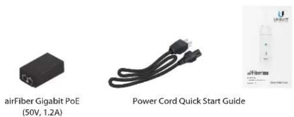
TERMS OF USE: Ubiquiti radio devices must be professionally installed. Shielded Ethernet cable and earth grounding must be used as conditions of product warranty. TOUGHCable 26 is designed for outdoor installations. It is the customer's responsibility to follow local country regulations, including operation within legal frequency channels, output power, and Dynamic Frequency Selection (DFS) requirements.
airFiber Configuration Interface System Requirements
- Microsoft Windows 7, Windows 8; Linux; or Mac OS X
• Java Runtime Environment 1.6 (or above) - Web Browser: Mozilla Firefox, Google Chrome, Microsoft Edge, or Microsoft Internet Explorer 11
Hardware Overview
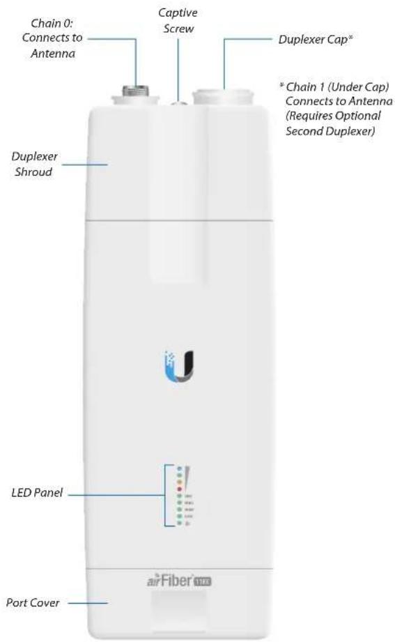
Ports
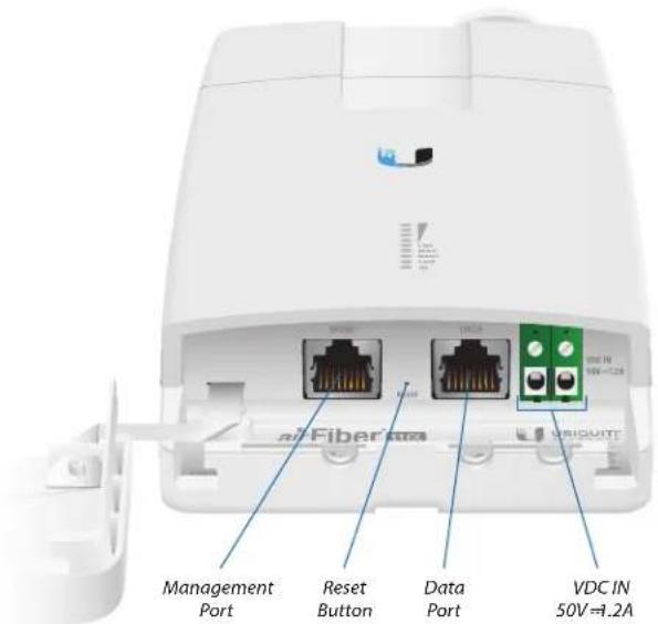
Management Port 10/100 Mbps, secured Ethernet port for configuration. In-Band Management is enabled by default in the airFiber Configuration Interface. When In-Band Management is disabled, the MGMT port is the only port that can monitor, configure, and/or update firmware.
Reset Button To reset to factory defaults, press and hold the Reset button for more than 10 seconds while the device is powered on.
Data Port Gigabit PoE port for handling all user traffic and powering the device.
VDC IN The terminal block can be used to power the AF-11FX with +50VDC =1.2A DC power instead of PoE.
Duplexer Ports
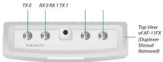
TX 0, RX 0 The TX and RX SMA ports for the Chain 0 Low-Band Duplexer or High-Band Duplexer (SISO and MIMO modes).
RX 1, TX 1 The RX and TX SMA ports for the Chain 1 Low-Band Duplexer or High-Band Duplexer (MIMO mode only). In SISO mode, these unused ports are protected by the Duplexer Cap.
Duplexer
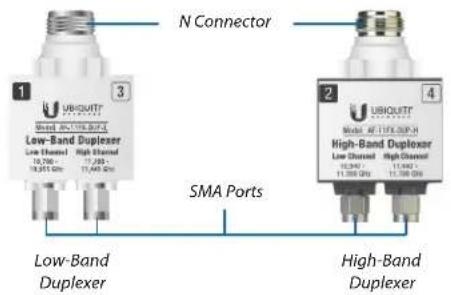
N Connector Female N-type connector into which the antenna cable is plugged.
SMA Ports High-band and low-band channel SMA ports.
LEDs
Signal LEDs
Signal 4 LED will light blue when on.
Signal 3 LED will light green when on.
Signal 2 LED will light yellow when on.
Signal 1 LED will light red when on.
Bootup to airOS When powering on, the Power, MIMO, LINK, and Signal 1-4 LEDs light on. Once the CPU code takes over, the MIMO, LINK, and Signal 1-3 LEDs turn off. The Signal 4 LED remains lit to indicate the boot sequence is underway.
Initializing airFiber Software When the airFiber application begins to boot under airOS, the Signal 4 LED goes from solidly on to a 2.5 Hz flash. This continues until the AF-11FX radio is fully booted.
Signal Level Once fully booted, the Signal 1-4 LEDs act as a bar graph showing how close the AF-11FX is to ideal aiming. This is auto-scaled based on the link range, the antenna gains, and the configured TX power of the remote AF-11FX. Each Signal LED has three possible states: On, Flashing, and Off. All Signal LEDs would be solidly on in an ideal link. For example, if the link has a 1 dB loss, the Signal 4 LED will flash; a 2 dB loss and the Signal 4 LED will turn off. The full bar graph LED states are shown below.
| dB loss | 0 | -1 | -2 | -3 | -4 | -5 | -6 | -7 | -8 | -9 | -10 | -11 | -12 | -13 |
| 1 | F | 0 | 0 | 0 | 0 | 0 | 0 | 0 | 0 | 0 | 0 | 0 | 0 | |
| 1 | 1 | 1 | F | 0 | 0 | 0 | 0 | 0 | 0 | 0 | 0 | 0 | 0 | |
| 1 | 1 | 1 | 1 | 1 | F | F | 0 | 0 | 0 | 0 | 0 | 0 | 0 | |
| 1 | 1 | 1 | 1 | 1 | 1 | 1 | 1 | 1 | 1 | F | F | F | 0 |
0 = Off, 1 = On, F = Flashing
Additional LEDs
| LED State Status | ||
| LINK | Off RF Off | |
| Short Flash* Syncing | ||
| Normal Flash* Beaconing | ||
| Long Flash* Registering | ||
| On Operational | ||
| MIMO | Off Radio configured in SISO Mode | |
| On Radio configured in MIMO Mode | ||
| MGMT | Off No Ethernet Link | |
| On Ethernet Link Established | ||
| Random Flashing Ethernet Activity | ||
| DATA | Off No Ethernet Link | |
| On Ethernet Link Established | ||
| Random Flashing Ethernet Activity | ||
| ⏻ | Off No Power | |
| On Powered On | ||
* Short Flash (1:3 on/off cycle)
Normal Flash (1:1 on/off cycle)
Long Flash (3:1 on/off cycle)
Chapter 1: Overview airFiber AF-11FX User Guide
Chapter 2: Installation
Installation Requirements
The airFiber AF-11FX radio is designed for use with the airFiber X antenna model AF-11G35. (Check your local/regional regulations for the allowable antenna gain allowed for your application.)
See the antenna's Quick Start Guide for antenna installation instructions.
Other Requirements
• Clear line of sight between airFiber X radios
• Vertical mounting orientation
- Mounting point:
- At least 1 m below the highest point on the structure
- For tower installations, at least 3 m below the top of the tower
- Ground wires – min. 10 AWG (5 mm 2 ) and max. length: 1 m. As a safety precaution, ground the airFiber X radio to grounded masts, poles, towers, or grounding bars.

WARNING: Failure to properly ground your airFiber X radio will void your warranty.
• (Recommended) 2 Outdoor Gigabit PoE surge protectors

Note: For guidelines about grounding and lightning protection, follow your local electrical regulatory codes.
- (Optional) For MIMO mode operation: A second Duplexer of the same type as the one included with the AF-11FX radio:
• High-Band Duplexer (model AF-11FX-DUP-H) or
• Low-Band Duplexer (model AF-11FX-DUP-L) - (Optional) If not using PoE: DC power source and 12/30 AWG power cable.
- Outdoor, shielded Category 6 (or above) cabling and shielded RJ-45 connectors are required for all wired Ethernet connections.
Installation Overview
We recommend to configure your paired AF-11FX radios before site installation. The overview below summarizes the installation procedure, and the subsequent sections provide detailed installation information:
• Install the Duplexer(s) in the AF-11FX radio.
- Connect the airFiber Gigabit PoE adapter to the DATA port, and connect your computer to the MGMT port.
- Configure the AF-11FX.
• Install a ground wire and mount the AF-11FX on the airFiber AF-11G35 antenna (or a compatible antenna).
- At the installation site, install the antenna with the mounted AF-11FX radio (see the antenna's Quick Start Guide for installation instructions).
- Connect the DATA port to your LAN, and connect power (PoE or DC power) to the AF-11FX.
- Establish and optimize the RF link..
Installing the Duplexer for SISO Mode
- Loosen the Captive Screw on top of the Duplexer Shroud and remove the Duplexer Shroud.
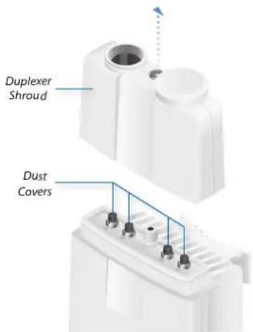
- Remove the Dust Covers from the TX 0 and RX 0 ports of the AF-11FX radio. Do not remove the Dust Covers from the RX 1 and TX 1 ports.
- Seat the SMA Ports of the Duplexer onto the TX 0 and RX 0 ports of the AF-11FX, while positioning the Low Channel and High Channel ports to yield the required transmit and receive frequencies.
- Secure the Duplexer to the radio by tightening the collars on the SMA Ports.


WARNING: Tighten the collars alternately, turning one collar a half turn, then the other a half turn, and so on, until both are fully tightened. Failure to do so may result in damage to the Duplexer.
Chapter 2: Installation airFiber AF-11FX User Guide
- Reseat the Duplexer Shroud onto the AF-11FX radio and tighten the Captive Screw to secure the Duplexer Shroud.

- Repeat steps 1-4 for the radio to be used on the other end of the link, ensuring that the numbers on the second radio's Duplexer are in the reverse order of the numbers on first radio's Duplexer.

Note: For example, if the numbers on the first radio's Duplexer are (left to right) 1/3, then the numbers on the second radio's Duplexer should be 3/1.
Installing an Optional Duplexer (MIMO Mode)

Note: MIMO operation requires two licenses, one per polarization and a second Duplexer of the same band.
- Loosen the Captive Screw on top of the Duplexer Shroud and remove the Duplexer Shroud.

-
Remove the Dust Covers from the radio's four SMA ports.
-
Seat the SMA Ports of one Duplexer onto the TX 0 and RX 0 ports of the AF-11FX, while positioning the Low Channel and High Channel ports to yield the required transmit and receive frequencies.
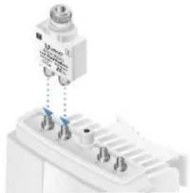
- Attach the second Duplexer (not included) to the RX 1 and TX 1 ports, ensuring that the numbers on the adjacent sides of the Duplexers match. (The numbers on the Duplexer on the right should be in the reverse order of the numbers on the Duplexer on the left.)
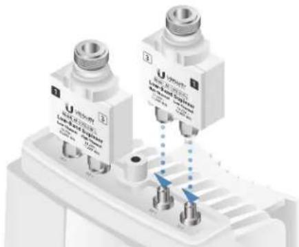
- Secure each Duplexer to the radio by tightening the collars on the SMA Ports.

WARNING: Tighten the collars alternately, turning one collar a half turn, then the other a half turn, and so on, until both are fully tightened. Failure to do so may result in damage to the Duplexer.
- Remove the Duplexer Cap and Cap Washer from the AF-11FX by removing the Cap Screw located inside the shroud.

- Reseat the Duplexer Shroud onto the AF-11FX radio and tighten the Captive Screw to secure the Duplexer Shroud.
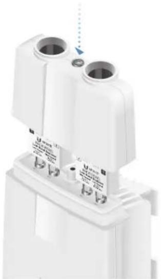
- Repeat steps 1-7 for the other radio to be used in the link, ensuring that the numbers on the second radio's Duplexers are in the reverse order of the numbers on the first radio's Duplexers.

Note: For example, if the numbers on the first radio's Duplexers are (left to right) 1/3 and 3/1, then the numbers on the second radio's Duplexers should be 3/1 and 1/3.
Connecting Power over Ethernet
- Lift the release latch on the bottom of the AF-11FX and slide the Port Cover off.

- Connect an Ethernet cable to the DATA port.
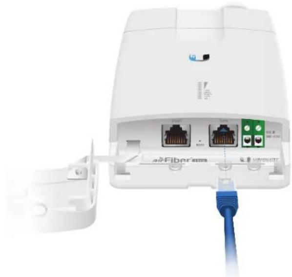
- Connect the Ethernet cable from the DATA port of the AF-11FX to the POE port of the adapter.

WARNING: Use only the included airFiber PoE adapter, Model GP-C500-120G. Failure to do so can damage the unit and void the product warranty.

- Connect the Power Cord to the power port on the airFiber PoE Adapter. Connect the other end of the Power Cord to a power source.
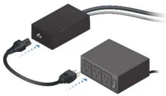
Chapter 2: Installation airFiber AF-11FX User Guide
airFiber Configuration
The instructions in this section explain how to access the airFiber Configuration Interface and configure the following settings:
- Wireless Mode Configure one AF-11FX radio as the Master and the other as the Slave.
-
Frequency Setting The TX Frequency and RX Frequency must be the reverse of each other on both the Master and the Slave.
-
Connect an Ethernet cable from your computer to the MGMT port on the AF-11FX radio.
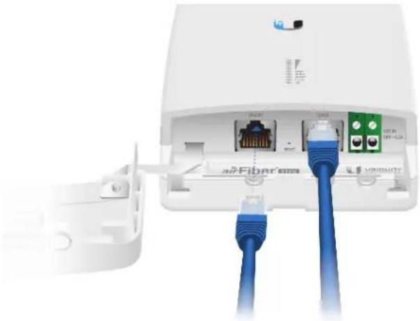
- Configure the Ethernet adapter on your computer with a static IP address on the 192.168.1.x subnet.
- Launch your web browser. Type http://192.168.1.20 in the address field and press enter (PC) or return (Mac).

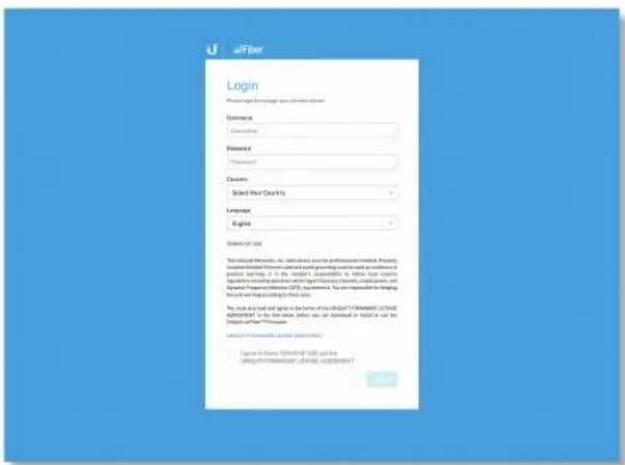
- The login screen will appear. Enter ubnt in the Username and Password fields. Select your Country and Language. You must agree to the Terms of Use to use the product. Click Login.
- Click Settings, and then click the Wireless tab.
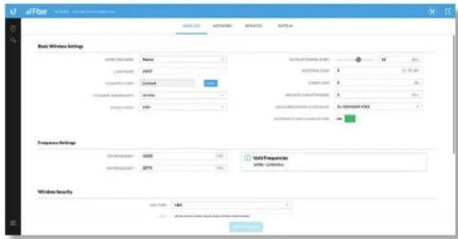
- Configure the Basic Wireless Settings:
a. For one AF-11FX, select Master as the Wireless Mode. For the other AF-11FX radio, keep the default, Slave.
b. Enter a name in the Link Name field. This should be the same on both the Master and the Slave.
c. If needed, change the Channel Bandwidth, Output Power, and/or Maximum Modulation Rate settings.
- Configure the TX Frequency Setting and RX Frequency.

Note: One airFiber X radio's TX Frequency is the other radio's RX Frequency, and vice versa.
- Configure the Wireless Security:
a. Select the Key Type, HEX or ASCII.
b. For the Key field:
- HEX Enter 16 bytes (eight, 16-bit hexadecimal digits: 0-9, A-F, or a-f). You can omit zeroes and use colons, similar to the IPv6 format.

Note: The airFiber Configuration Interface supports IPv6 formats excluding dotted quad and “::” (double-colon) notation.
- ASCII Enter a combination of alphanumeric characters (0-9, A-Z, or a-z).
-
Click Save Changes.
-
In-Band Management is enabled by default, so each AF-11FX radio must have a unique IP Address. (If the AF-11FX radios use the same IP Address, you may lose access to the radios via the DATA ports.) Click the Network tab.

a. For the Management IP Address option:
- DHCP Keep the default, DHCP, to use DHCP reservation on your router to assign a unique IP Address.
- Static Change the IP Address, Netmask, and other settings to make them compatible with your network.
b. Click Save Changes.
- Disconnect the Ethernet cables from the MGMT and DATA ports on the AF-11FX. Configuration of the AF-11FX radio is complete.
Repeat the instructions in the airFiber Configuration section on the other AF-11FX radio.
Hardware Installation
Install a Ground Wire
- Remove the nut from the Ground Bonding Point located on the back of the AF-11FX, near the lower-right corner.

- Attach a ground wire (min. 10 AWG or 5mm2 ) to the lug and replace the nut to secure the wire.

- At the installation site, secure the other end of the ground wire to a grounded mast, pole, tower, or grounding bar.

WARNING: Failure to properly ground your airFiber X radio will void your warranty.

Note: The ground wire should be as short as possible and no longer than one meter in length.
Mount to the airFiber X Antenna
Follow the instructions in this section to mount the AF-11FX radio to an airFiber X AF-11G35 antenna:
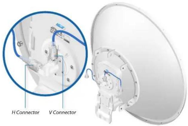
- Attach an RF Cable to an RF connector labeled H or V. Then slide the silicone boot over the RF connector to protect it.

Note: For SISO mode, use the RF connector (H or V) as determined by your licensing. Keep the other RF connector covered with the included Metal Cap.
If using MIMO mode, remove the cap over the second RF connector (V or H) and attach an RF Cable. Then slide the silicone boot over the RF connector to protect it.
- Attach the AF-11FX radio to the antenna by aligning the four tabs on the back of the radio with the slots of the radio mount. Then slide the radio down to lock it into place.

Chapter 2: Installation airFiber AF-11FX User Guide
-
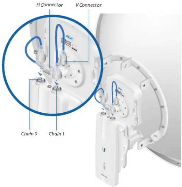
Connect the RF Cable(s) (one in SISO mode, two in MIMO mode) to the radio as follows:
-
Attach the RF Cable from the H Connector to the radio's Chain 0 connector.
- Attach the RF Cable from the V Connector to the radio's Chain 1 connector.
- Attach the protective shroud.
a. Align the dot on the top of the shroud with the arrow on the dish antenna.
b. Guide the shroud's tabs into the slots on the antenna.
c. Push the shroud in and then pull it down until it locks into place.
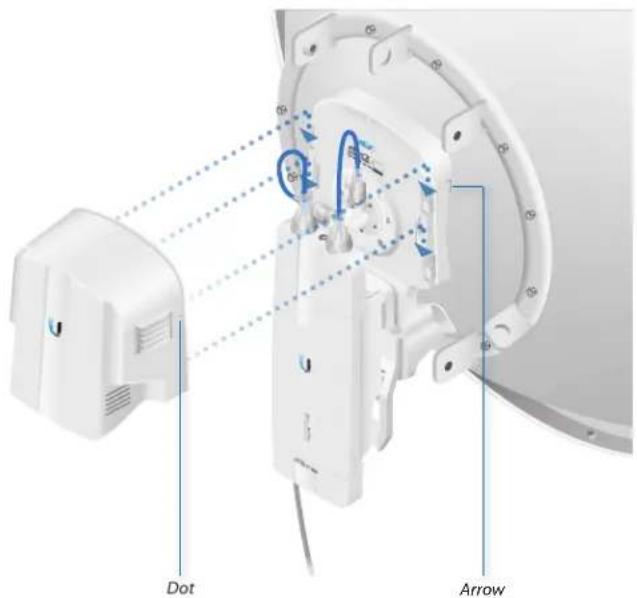
Connecting Data
- Lift the release latch on the bottom of the AF-11FX and slide the Port Cover off.

- Connect an outdoor, shielded Ethernet cable to the DATA port.

- If you are using DC power, connect the other end of the Ethernet cable to your LAN.
Connecting Power
Follow the instructions for the source of power that you are using: Power over Ethernet or DC Power.
Power Over Ethernet
- Connect the Ethernet cable from the DATA port of the AF-11FX to the POE of the adapter.

WARNING: Use only the included adapter, model GP-C500-120G. Failure to do so can damage the unit and void the product warranty.
- Connect an Ethernet cable from your LAN to the adapter's LAN port.
- Connect the Power Cord to the adapter's power port. Connect the other end of the Power Cord to a power outlet.

DC Power
- Connect a DC power cable to the Terminal Block. (The +VDC and GND can be connected to either terminal.)
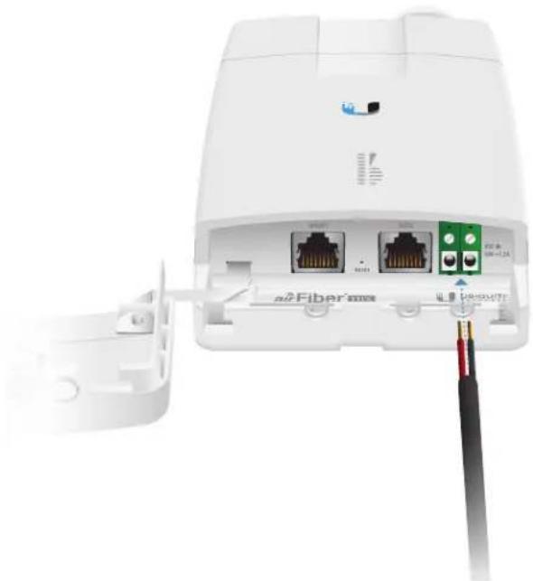
- Connect the other end of the DC power cable to a DC power supply that supplies +50VDC.

WARNING: Applying a negative voltage such as -48VDC will damage the radio.
- Connect the DC power supply to its source.
Surge Protection
For added protection, install two surge suppressors, such as the Ubiquiti Ethernet Surge Protector, model ETH-SP, at the end of each link. Install the first surge protector within one meter of the airFiber DATA port, and install the second surge protector at the ingress point of the location housing the wired network equipment.

Alignment
Tips
• To accurately align the airFiber X radios for best performance, you MUST align only one end of the link at a time.
- You may need to use additional hardware to compensate for issues such as the improper orientation of a mounting pole or significant elevation differences between airFiber X radios.
Establishing a Link
Adjust the positions of the Master and the Slave to establish a link. The following section features the airFiber X antenna, AF-11G35.

Note: The Master must be aimed first at the Slave because the Slave does not transmit any RF signal until it detects transmissions from the Master.

Note: For complete details on the antenna, refer to the Quick Start Guide for your specific model.
- Master Visually aim the Master at the Slave. To adjust the Master's position, adjust the azimuth and elevation:
Adjust the azimuth:
a. Loosen the four flange nuts on the two pole clamps.
b. Rotate the antenna to point towards the other end of the link.
c. Tighten the four flange nuts on the two pole clamps.

Adjust the elevation angle:
a. Loosen the eight hex head bolts to so that the washers can spin freely by hand.
b. Tighten or loosen the Elevation Adjustment Bolt to set the desired tilt.
c. Tighten the eight hex head bolts.


Note: Do NOT make simultaneous adjustments on the Master and Slave.
- Slave Visually aim the Slave at the Master. To adjust the Slave's position, adjust the azimuth and elevation as described in step 1.
- Check to see if a link is established. Ensure that the LINK LED is solidly lit green and the Signal LEDs of the Slave are displaying signal levels.

- Slave Aim the Slave at the Master to achieve the strongest signal level on the Master.

Note: Refer to "Signal LEDs" on page 2 for details on the signal values.

Note: Maximum signal strength can best be achieved by iteratively sweeping through both azimuth and elevation.
- Master Aim the Master at the Slave to achieve the strongest signal level on the Slave.
- Repeat steps 4 and 5 until you achieve an optimal link, with all four Signal LEDs solidly lit. This ensures the best possible data rate between the airFiber X radios.
- Lock the alignment on both airFiber X antennas by tightening all the nuts and bolts.
- Observe the Signal LEDs of each airFiber X radio to ensure that the values remain constant while tightening the nuts and bolts. If any LED value changes during the locking process, loosen the nuts and bolts, finalize the alignment of each airFiber X antenna again, and retighten the nuts and bolts.
Refer to the following chapters of this User Guide for details on the airFiber Configuration Interface:
• "Dashboard" on page 17
• "Wireless Tab" on page 21
• "Network Tab" on page 25
• "Services Tab" on page 29
• "System Tab" on page 33
• "Tools" on page 37
Installer Compliance Responsibility
Devices must be professionally installed and it is the professional installer's responsibility to make sure the device is operated within local country regulatory requirements.
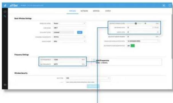
The Output Power, Antenna Gain, Cable Loss*, TX Frequency, and RX Frequency fields are provided to the professional installer to assist in meeting regulatory requirements.
* Cable Loss includes loss due to the Duplexer(s).
Chapter 2: Installation airFiber AF-11FX User Guide

Chapter 3: Navigation
The airFiber Configuration Interface is an advanced operating system capable of powerful wireless and routing features, built upon a simple and intuitive user interface foundation.
The airFiber X radio uses the airFiber Configuration Interface for easy configuration and management via a web browser.
There are two ways to access the airFiber Configuration Interface:
- Management Port Enabled by default. Use a direct connection to the Management port for out-of-band management.
- In-Band Management Enabled by default. In-band management is available through the local Data port or the Data port at the other end of the link. You can disable it on the Network tab. (See "Management Network Settings" on page 25 for more details.)
Accessing the airFiber Configuration Interface
Connect to the airFiber Configuration Interface.
- Make sure that your host machine is connected to the LAN that is connected to the Management port on the airFiber X radio.
-
Configure the Ethernet adapter on your host system with a static IP address on the 192.168.1.x subnet (for example, 192.168.1.100).
-
Launch your web browser. Type http://192.168.1.20 in the address field and press enter (PC) or return (Mac).

- Upon initial login, the Terms of Use appear on the login screen. Enter ubnt in the Username and Password fields, and select the appropriate choices from the Country and Language drop-down lists. Check the box next to I agree to these Terms of Use and the Ubiquiti Firmware License Agreement, and click Login.

- The airFiber Configuration Interface will appear, allowing you to customize your settings as needed.
Interface Pages
The airFiber Configuration Interface contains two main pages: Dashboard and Settings. Each web-based management page is used to configure a specific aspect of the AF-11FX device, and is accessed by clicking the appropriate icon in the navigation bar on the left side of the interface:
| Icon Web-Based Management Page | |
| Dashboard The “Dashboard” on page 17 displays read-only device status, statistics, and network monitoring links. The Dashboard is displayed by default when the airFiber Configuration interface is opened. | |
| Displays the Settings page which contains the following tabs:Wireless The “Wireless Tab” on page 21 configures basic wireless settings, including the wireless mode, link name, TX and RX frequency, output power, speed, and wireless security, as well as advanced wireless settings.Network The “Network Tab” on page 25 configures the management network settings, Internet Protocol (IP) settings, management VLAN, automatic IP aliasing, and data port Ethernet settings.Services The “Services Tab” on page 29 configures system management services: Ping Watchdog, Simple Network Management Protocol (SNMP), servers (web, SSH, telnet), Network Time Protocol (NTP) client, Dynamic Domain Name System (DDNS) client, system log, and device discovery.System The “System Tab” on page 33 controls firmware update, device customization, date settings, administrator account management, location management, and device maintenance (device reboot, factory default reset, configuration backup and upload, and support information download). You can also change the language of the web management interface. | |
At the lower left and upper right of the window are icons used to access additional tools and information:
| Icon Web-Based Management Page | |
| Displays the system log. See“Log” on page 40. | |
| Displays a list of network administration and monitoring tools. See“Tools” on page 37. | |
| Click this icon to immediately log out of the airFiber Configuration Interface. | |
Configuration Interface Notifications
Pending Changes
When you make changes to any settings on any page, the following buttons appear at the bottom of the page

Use the buttons to perform operations on all unsaved changes. You have three options:
Test Changes Click Test Changes to try changes without saving them. You have two options:
- Apply Click Apply to save changes.
- Discard Click Discard to cancel changes.
Note: If you do not click Apply within 180 seconds (the countdown is displayed), the device times out and resumes its earlier configuration.
Revert Changes Click Revert Changes to cancel all changes on all pages.
Save Changes Click Save Changes to immediately apply and save changes.
Product Verification
The airFiber Configuration Interface will verify whether a product is genuine or counterfeit.
For a genuine airFiber radio, the airFiber Configuration Interface will display a Genuine Product logo at the bottom of the Dashboard.

For any product that is not an official Ubiquiti product, the airFiber Configuration Interface will display a counterfeit warning. Please contact Ubiquiti at support@ubnt.com regarding this product.


Chapter 4: Dashboard
The Dashboard displays a read-only summary of the current link status information; local and remote device signal strength, capacity, and speed information; current values of the basic configuration settings, device settings and information, and Ethernet network status.
Link Status
The Link Status section of the Dashboard displays status information for the link as well as statistics for the Local and Remote ends of the link.

Link Name Displays the name assigned to the link.
(Link Distance) Displays the distance between the remote and local airFiber X radios.
Local
Device Name Displays the customizable name or identifier of the device. The Device Name (or host name) is displayed in registration screens and discovery tools.
MAC Address Displays the local radio's Management Ethernet MAC address.
Receive Capacity Displays the local device's potential RX throughput (how much the airFiber X radio can receive, after accounting for the modulation and error rates).
TX Power (EIRP) Displays the current average transmit output power (in dBm) of the local AF-11FX radio.
Conducted Displays the conducted transmit power out of the radio before any antenna gain.
Antenna Gain Displays the local antenna's gain in dBi.
RX Frequency Displays the frequency that the local AF-11FX radio is using to receive data.
RX Channel Width Displays the width of the channel that the local AF-11FX radio is using to receive data.
TX Frequency Displays the frequency that the local AF-11FX radio is using to transmit data.
TX Channel Width Displays the width of the channel that the local AF-11FX radio is using to transmit data.
Remote
Receive Capacity Displays the remote device's potential RX throughput (how much the airFiber X radio can receive, after accounting for the modulation and error rates) in Mbps.
TX Power (EIRP) Displays the current average transmit output power (in dBm) of the remote AF-11FX radio.
Remote IP Displays the Management Ethernet IP address of the remote AF-11FX radio.
MAC Address Displays the Management Ethernet MAC address of the remote AF-11FX radio.
Signal Strength
The Signal Strength section displays signal strength, capacity, and speed information.

Local
Signal Strength Displays the signal strength for Chain 0 and Chain 1.
Ideal Power Displays the ideal power level of the received signal.
Chain Imbalance Displays the difference between the actual and ideal power levels.
Local RX Real-Time Capacity/Speed Charts for Capacity (orange) and Throughput (blue) display the potential and current RX data traffic.
Modulation Rate Displays the current modulation rate:
| MIMO SISO | |
| 10x (1024QAM) 5x (1024QAM) | |
| 8x (256QAM) 4x (256QAM) | |
| 6x (64QAM) 3x (64QAM) | |
| 4x (16QAM) 2x (16QAM) | |
| 2x (QPSK) 1x (QPSK) | |
| 1x (QPSK) 1/4x (QPSK) | |
| 1/4x (QPSK) – | |
If Automatic Rate Adaptation is enabled on the Wireless tab, then Modulation Rate displays the current speed in use and depends on the Maximum Modulation Rate specified on the Wireless tab and current link conditions.
Remote
Signal Strength Displays the signal strength for Chain 0 and Chain 1.
Ideal Power Displays the ideal power level of the received signal.
Chain Imbalance Displays the difference between the actual and ideal power levels.
Remote RX Real-Time Capacity/Speed Charts for Capacity (orange) and Throughput (blue) display the potential and current RX data traffic.
Modulation Rate Displays the current modulation rate (see Modulation Rate description in the Local section above).
If Automatic Rate Adaptation is enabled on the Wireless tab, then Modulation Rate displays the current speed in use and depends on the Maximum Modulation Rate specified on the Wireless tab and current link conditions.
Device

Operating Mode Displays the mode of the airFiber X radio: Slave, Master, or Reset.
RF Link Status Displays the status of the airFiber X radio: RF Off, Syncing, Beaconing, Registering, Enabling, Listening, Operational, DFS CAC, or RADAR Detected.
Note: Most RF Link Status values map to specific flash rates of the Link Status LED (See "LEDs" on page 2 for more details.)
| Status Flash Rate of LED | |
| RF Off Off | |
| Beaconing Normal Flash (1:1 on/off cycle) | |
| Registering Long Flash (3:1 on/off cycle) | |
| Operational On | |
Version Displays the airFiber Configuration Interface software version.
Date Displays the current system date and time. The date and time are displayed in YEAR-MONTH-DAY HOURS:MINUTES:SECONDS format. The system date and time is retrieved from the Internet using NTP (Network Time Protocol). The NTP Client is enabled by default on the Services tab. The airFiber X radio has no internal clock, and the date and time may be inaccurate if the NTP Client is disabled or the device is not connected to the Internet.
Radio Mode Displays the radio mode: MIMO or SISO.
Uptime This is the total time the device has been running since the latest reboot (when the device was powered up) or software upgrade. The time is displayed in days, hours, minutes, and seconds.
Link Uptime This is the total time the airFiber link has been continuously operational. The time is displayed in days, hours, minutes, and seconds.
Regulatory Domain Displays the regulatory domain (FCC/IC, ETSI, or Other), as determined by country selection.
Security AES-128 is enabled at all times.
Conducted TX Power Displays the conducted transmit power out of the radio before any antenna gain.
Net Gain Displays the airFiber X radio's net antenna gain, which is the antenna gain minus cable loss. Antenna gain (the gain of the antenna being used) and cable loss (the loss in the cable from the radio to the antenna) are set using the Antenna Gain and Cable Loss fields on the Wireless tab.
(Ant Gain/Cable Loss) Displays the airFiber X radio's net antenna gain, which is the antenna gain minus cable loss. Antenna gain (the gain of the antenna being used) and cable loss (the loss in the cable from the radio to the antenna, including approx. 1 dB due to the Duplexers) are set using the Antenna Gain and Cable Loss fields on the Wireless tab.
Ethernet

MGMT MAC Displays the MAC address of the Management port.
MGMT Displays the speed and duplex of the Management port.
DATA Displays the speed and duplex of the Data port.
DATA Cable Length Displays the Ethernet cable length from radio to remote port. This is displayed only for cables longer than 20 m.
DATA Pair 0 (Pins 1,2) If the cable is functioning properly, displays the SNR of the twisted pair; if the cable has a fault, displays the fault ("open" or "short") and the distance at which the fault has occurred. If the remote port is administratively shut down, this field displays "normal".
DATA Pair 1 (Pins 3,6) If the cable is functioning properly, displays the SNR of the twisted pair; if the cable has a fault, displays the fault ("open" or "short") and the distance at which the fault has occurred. If the remote port is administratively shut down, this field displays "normal".
DATA Pair 2 (Pins 4,5) If the cable is functioning properly, displays the SNR of the twisted pair; if the cable has a fault, displays the fault ("open" or "short") and the distance at which the fault has occurred. If the remote port is administratively shut down, this field displays "normal".
DATA Pair 3 (Pins 7,8) If the cable is functioning properly, displays the SNR of the twisted pair; if the cable has a fault, displays the fault ("open" or "short") and the distance at which the fault has occurred. If the remote port is administratively shut down, this field displays "normal".
airFiber AF-11FX User Guide

Chapter 5: Wireless Tab
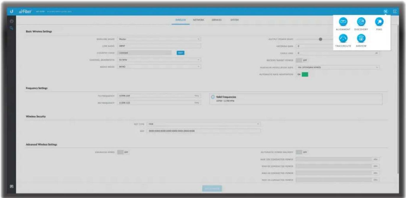
The Wireless tab contains options to set up the wireless part of the link. This includes wireless mode, link name, frequencies, output power, speed, wireless security, and advanced wireless settings.
Test Changes To try the changes without saving them, click Test Changes. A new message appears. You have two options:
- Apply To immediately save your changes, click Apply.
- Discard To cancel your changes, click Discard. If you do not click Apply within 180 seconds (the countdown is displayed), the AF-11FX radio resumes its earlier configuration.
Revert Changes To cancel your changes, click Revert Changes.
Save Changes To save your changes, click Save Changes.
Write down the settings you configure on the Wireless tab. You will need to enter the same settings on the AF-11FX radio at the other end of your PtP link. The exceptions are as follows:
- Wireless Mode Configure one AF-11FX radio as the Master and the other as the Slave.
- TX Frequency, RX Frequency The TX Frequency and RX Frequency on one AF-11FX radio are configured as the RX Frequency and TX Frequency, respectively, on the other radio.
Basic Wireless Settings
In this section, configure the basic wireless settings, such as wireless mode, link name, country code, frequencies, output power, speed, and gain.

Wireless Mode By default, the Wireless Mode is Slave. You must configure one airFiber X radio as Master because each PtP link must have one Master.
Link Name Enter a name for your PtP link. This name must be the same on both Master and Slave radios in order for them to connect.
Country Code This is preset to Licensed and cannot be changed.
Channel Bandwidth Select the appropriate channel size: 3.5, 5, 7, 10, 14, 20, 28, 30, 40, 50, or 56 MHz.

Note:. The available channel bandwidths depend on the regulatory requirements of the currently selected country or region.
Radio Mode Use this setting to configure the mode of the radio to MIMO or SISO.
Output Power (EIRP) Defines the maximum average transmit output power (in dBm) of the airFiber X radio. To specify the output power, use the slider or manually enter the output power value. The transmit power level maximum is limited according to country regulations.

Note: The Antenna Gain and Cable Loss should be configured before the Output Power. This is because the range of the Output Power field is affected by the Antenna Gain and Cable Loss values – changing the antenna gain or cable loss adjusts the maximum and minimum values you can select using the Output Power slider. Since the Output Power already includes the antenna gain and cable loss, it represents EIRP; therefore, the value of Output Power is actually the total power the radio is transmitting over the air. The current transmit power is displayed by the TX Power (EIRP) field on the Dashboard.

Note: The airFiber X radio may limit the output power to a value less than the value specified by this field, to comply with regulatory region requirements. For a list of maximum output power values by country and region, refer to "Frequency Ranges and Power Levels per Country/Region" on page 47.
Antenna Gain Enter the gain in dBi of the antenna that is used in your installation. An improper value could cause DFS false detections when operating on DFS frequencies.
Cable Loss Enter the cable loss in dB of the cable that is used in your installation. An improper value could cause DFS false detections when operating on DFS frequencies.
Receive Target Power To use the Automatic Transmit Power Control (ATPC) feature, enable this option and enter the desired power level that the receiver (on the far end of the link) should see from this radio.
In ATPC, each airFiber X radio monitors the amount of power received by the radio at the other end of the link. If the reported value differs from the Receive Target Power value, the radio automatically adjusts its transmit output power to match the Receive Target Power value. The radio will use its Output Power (EIRP) setting as the maximum level at which it will transmit to maintain the Receive Target Power.
Maximum Modulation Rate or Modulation Rate Higher modulations support greater throughput but generally require stronger RF signals and a higher Signal-to-Noise Ratio (SNR). By default, Automatic Rate Adaptation is enabled, and Maximum Modulation Rate is displayed. This allows the airFiber X radio to automatically adjust the modulation rate to changing RF signal conditions. Under certain conditions, you may prefer to lock the Maximum Modulation Rate to a lower setting to improve link performance.
When Automatic Rate Adaptation is disabled, Modulation Rate is displayed. Lock the Modulation Rate to the setting of your choice.
Select one of the available modulation rates. The available values depend on the Radio Mode setting:
• If Radio Mode is set to MIMO:
• 10x (1024QAM MIMO)
• 8x (256QAM MIMO)
- 6x (64QAM MIMO)
• 4x (16QAM MIMO)
• 2x (QPSK MIMO)
• 1x (QPSK SISO)
• 1/4x (QPSK SISO)
• If Radio Mode is set to SISO:
• 5x (1024QAM SISO)
• 4x (256QAM SISO)
• 3x (64QAM SISO)
• 2x (16QAM SISO)
• 1x (QPSK SISO)
- 1/4x (QPSK SISO)
Automatic Rate Adaptation Enabled by default, this option allows the airFiber X radio to automatically adjust the modulation rate to changing RF signal conditions.
Frequency Settings
The Valid Frequencies for your Country Code selection are displayed. Ensure that you use frequencies that comply with the local country regulations.

TX Frequency Enter a valid TX frequency. The current state is displayed.
RX Frequency Enter a valid RX frequency. The current state is displayed.
Wireless Security
airFiber uses 128-bit, AES (Advanced Encryption Standard) encryption at all times.

Key Type Specifies the character format.
- HEX By default, this option uses hexadecimal characters. 0-9, A-F, or a-f are valid characters.
- ASCII ASCII uses the standard English alphabet and numeric characters (0-9, A-Z, or a-z).
Key Select the format of the MAC address.
- HEX Enter 16 bytes (eight, 16-bit hexadecimal values). You can omit zeroes and use colons, similar to the IPv6 format. The default is:
0000:0000:0000:0000:0000:0000:0000:0000

Note: The airFiber Configuration Interface supports IPv6 formats excluding dotted quad and “::” (double-colon) notation.
- ASCII Enter a combination of alphanumeric characters. Using 128-bit SHA1 (Secure Hash Algorithm 1), the airFiber X radio hashes the ASCII key to create a 128-bit key for AES.
Advanced Wireless Settings

Enhanced MIMO Select this option to enable the Enhanced MIMO feature. Enhanced MIMO increases sensitivity which may result in greater TX throughput in low-noise environments. If enabling this feature does not result in improved throughput, the noise level is too high and you should disable this feature. This feature is disabled by default.
Automatic Power Backoff This feature allows the radio to automatically adjust the maximum TX power per modulation so that the radio never transmits at a higher power than each modulation rate can decode. The default values in the Max 10x/8x/6x/4x Conducted Power fields are values determined to work at all temperatures and all frequencies supported by the radio.
It may, however, be possible to increase the maximum TX power for one or more modulations based on your radio's operating environment. For example, if a radio is running at 6x and trying to switch into 8x operation, you can increase the Max 8x Conducted Power value 1 dB at a time to see if the radio can maintain 8x operation (Automatic Power Backoff must be enabled to allow the Max Conducted Power fields to be edited). The same can be done with 6x and 4x up to the maximum conducted power of the radio.
Max 10x/8x/6x/4x Conducted Power The maximum conducted power for the 10x/8x/6x/4x modulation rates. Each field is editable only if Automatic Power Backoff is enabled.
Restore Default Backoffs Click Restore to restore the default Max Conducted Power values.
airFiber AF-11FX User Guide

Chapter 6: Network Tab
The Network tab allows you to configure settings for the management network. There are two ways to access the airFiber Configuration Interface:
- Management Port Enabled by default. Use a direct connection to the Management port for out-of-band management.
- In-Band Management Enabled by default. In-band management is available through the local Data port or the Data port at the other end of the link.
The Management port and in-band management share the default IP address of 192.168.1.20.
Test Changes To try the changes without saving them, click Test Changes. A new message appears. You have two options:
- Apply To immediately save your changes, click Apply.
- Discard To cancel your changes, click Discard. If you do not click Apply within 180 seconds (the countdown is displayed), the AF-11FX radio resumes its earlier configuration.
Revert Changes To cancel your changes, click
Revert Changes.
Save Changes To save your changes, click Save Changes.
Management Network Settings
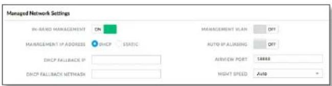
In-Band Management Enabled by default. In-band management is available through the local Data port or the Data port at the other end of the link.

Note: If In-Band Management is enabled, ensure that each airFiber X radio in a link has a unique IP Address. If the airFiber X radios use the same IP Address, you may lose access via the Data ports.
Management IP Address The airFiber X radio can use a static IP address or obtain an IP address from its DHCP server.
- DHCP Keep the default, DHCP, to use DHCP reservation on your router to assign a unique IP Address. The local DHCP server assigns a reserved IP address, gateway IP address, and DNS address to the airFiber X radio.

Note: If you select the DHCP option, ensure that you use DHCP reservation because if you do not know the IP address, then the only way to manage the airFiber X radio is to reset the airFiber X radio to its factory default settings. (Press and hold the Reset button for more than five seconds.) Its default Management IP Address is reset to 192.168.1.20.
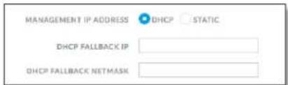
- DHCP Fallback IP Specify the IP address the airFiber X radio should use if a DHCP server is not found.
- DHCP Fallback Netmask Specify the netmask the airFiber X radio should use if a DHCP server is not found.
• Static Assign static IP settings to the airFiber X radio.

Note: IP settings should be consistent with the address space of the airFiber X radio's network segment.
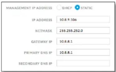
- IP Address Specify the IP address of the airFiber X radio. This IP will be used for device management purposes.
- Netmask When the netmask is expanded into its binary form, it provides a mapping to define which portions of the IP address range are used for the network devices and which portions are used for host devices. The netmask defines the address space of the airFiber X radio's network segment. The 255.255.255.0 (or "/24") netmask is commonly used on many Class C IP networks.
- Gateway IP Typically, this is the IP address of the host router, which provides the point of connection to the Internet. This can be a DSL modem, cable modem, or WISP gateway router. The airFiber X radio directs data packets to the gateway if the destination host is not within the local network.
- Primary DNS IP Specify the IP address of the primary DNS (Domain Name System) server.
- Secondary DNS IP Specify the IP address of the secondary DNS server. This entry is optional and used only if the primary DNS server is not responding.
Management VLAN If enabled, automatically creates a management Virtual Local Area Network (VLAN).
- VLAN ID Enter a unique VLAN ID from 2 to 4094.
Auto IP Aliasing If enabled, automatically generates an IP address for the corresponding WLAN/LAN interface. The generated IP address is a unique Class B IP address from the 169.254.X.Y range (netmask 255.255.0.0), which is intended for use within the same network segment only. The Auto IP always starts with 169.254.X.Y, with X and Y as the last two octets from the MAC address of the airFiber X radio. For example, if the MAC address is 00:15:6D:A3:04:FB, then the generated unique Auto IP will be 169.254.4.251. (The hexadecimal value, FB, converts to the decimal value, 251.)
The Auto IP Aliasing setting can be useful because you can still access and manage devices even if you lose, misconfigure, or forget their IP addresses. Because an Auto IP address is based on the last two octets of the MAC address, you can determine the IP address of a device if you know its MAC address.
airView Port The port number associated with the airView spectrum analyzer tool. The default value is 18888.
For detailed information on the airView tool, refer to "airView" on page 38.
Mgmt Speed This is the speed of the Management port. By default, the option is Auto. The airFiber X radio automatically negotiates transmission parameters, such as speed and duplex, with its counterpart. In this process, the networked devices first share their capabilities and then choose the fastest transmission mode they both support.
To manually specify the maximum transmission link speed and duplex mode, select one of the following options: 100 Mbps-Full, 100 Mbps-Half, 10 Mbps-Full, or 10 Mbps-Half. If you are running extra long Ethernet cables, a link speed of 10 Mbps could help to achieve better stability.
Full-duplex mode allows communication in both directions simultaneously. Half-duplex mode allows communication in one direction at a time, alternating between transmission and reception.
Data Port Ethernet Settings

DATA Speed This is the speed of the Data port.
The default is Auto, which allows the radio to operate at a speed of 1 Gbps. The airFiber X radio automatically negotiates transmission parameters, such as speed and duplex, with its counterpart. In this process, the networked devices first share their capabilities and then choose the fastest transmission mode they both support.
To manually specify the maximum transmission link speed and duplex mode, select one of the following options: 100 Mbps-Full, 100 Mbps-Half, 10 Mbps-Full, or 10 Mbps-Half.
Full-duplex mode allows communication in both directions simultaneously. Half-duplex mode allows communication in one direction at a time, alternating between transmission and reception.
Flow Control If enabled, the airFiber X radio generates and responds to Ethernet layer PAUSE frames. The airFiber X radio regulates inbound traffic from the customer's network to avoid buffer overflows within the airFiber X radio. Flow control has the effect of controlling the inter-packet spacing of packets headed into the airFiber Data interface.
Multicast Filter If enabled, the filter blocks multicast traffic from overloading the CPU when in-band management is enabled. This allows the airFiber X radio to be managed in-band when the customer's network is carrying large volumes of multicast traffic, such as IPTV. The filter does not block multicast traffic going over the radio; it simply blocks it from reaching the airFiber X radio's management interface CPU.
Ethernet Carrier Drop Settings
The Ethernet Carrier Drop settings are used to control failover switching between the primary and backup link in response to capacity loss due to rain.

Carrier Drop Operation This setting is used to control the Ethernet Carrier Drop feature. Settings are: Disabled, Enabled, and Use Pulse. The default is Disabled.
Use Pulse and Enabled are the two different methods used to signal to the failover mechanism that it should switch to the backup link:
- Use Pulse The LAN link is toggled off.
- Enabled The LAN link will be turned off and left off.
Pulse Duration (Available if Carrier Drop Operation is set to Use Pulse.) This is the length of time that the LAN link remains down to trigger failover. The default is 5 seconds.
Block Data After Pulse (Available if Carrier Drop Operation is set to Use Pulse.) Enable this option to stop data from passing through the link when it is experiencing loss of capacity. The default is Off.
Enable Ethernet If No Session Enable this option to allow management data (such as GUI, SNMP, and ping packets) to pass, even if the Block Data After Pulse option is enabled. The default is Off.
Wait for First Session Enable this option to cause the system to wait until the Ethernet link has been successfully established following a power cycle, to keep the link from being dropped due to the throughput being below threshold. The default is Off.
First Session Validation Timer Use this setting to specify how long to wait before triggering a link failure due to insufficient threshold capacity following a power cycle. The default is 0 seconds.
TX Capacity Low Threshold This is the minimum allowable TX capacity; if the TX capacity goes below this threshold, the Ethernet link will be dropped. The default is 0 Mbps.
TX Capacity High Threshold This is the TX capacity required before a dropped link can be declared to be operational again. The Ethernet link will remain down until the TX capacity reaches this threshold. The default is 0 Mbps. This setting should be greater than the TX Capacity Low Threshold to avoid flutter and multiple OSPF convergences.
RX Capacity Low Threshold This is the minimum allowable RX capacity; if the RX capacity goes below this threshold, the Ethernet link will be dropped. The default is 0 Mbps.
RX Capacity High Threshold This is the RX capacity required before a dropped link can be declared to be operational again. The Ethernet link will remain down until the RX capacity reaches this threshold. The default is 0 Mbps. This setting should be greater than the RX Capacity Low Threshold to avoid flutter and multiple OSPF convergences.
Low Threshold Timer This is the number of continuous seconds that the radio must remain under the minimum TX or RX capacity threshold before the link is dropped. If set to 0, then as soon as capacity drops below a set limit, the Ethernet link will be dropped. Default is 0 seconds.
High Threshold Timer This is the number of continuous seconds that the radio must remain above the maximum TX or RX capacity threshold before the link is declared operational again. The default is 0 seconds.
Chapter 6: Network Tab airFiber AF-11FX User Guide

Chapter 7: Services Tab
The Services tab configures system management services: Ping Watchdog, SNMP Agent, Web Server, SSH Server, Telnet Server, NTP Client, Dynamic DNS, System Log, and Device Discovery.
Test Changes To try the changes without saving them, click Test Changes. A new message appears. You have two options:
- Apply To immediately save your changes, click Apply.
- Discard To cancel your changes, click Discard. If you do not click Apply within 180 seconds (the countdown is displayed), the AF-11FX radio resumes its earlier configuration.
Revert Changes To cancel your changes, click
Revert Changes.
Save Changes To save your changes, click Save Changes.
Ping Watchdog
Ping Watchdog sets the airFiber X radio to continuously ping a user-defined IP address (the Internet gateway, for example). If it is unable to ping under the user-defined constraints, the airFiber X radio will automatically reboot. This option creates a kind of "fail-proof" mechanism.
Ping Watchdog is dedicated to continuous monitoring of the specific connection to the remote host using the Ping tool. The Ping tool works by sending ICMP echo request
packets to the target host and listening for ICMP echo response replies. If the defined number of replies is not received, the tool reboots the airFiber X radio.

Ping Watchdog Enables use of Ping Watchdog.
- IP Address To Ping Specify the IP address of the target host to be monitored by Ping Watchdog.
- Ping Interval Specify the time interval (in seconds) between the ICMP echo requests that are sent by Ping Watchdog. The default value is 300 seconds.
- Startup Delay Specify the initial time delay (in seconds) until the first ICMP echo requests are sent by Ping Watchdog. The default value is 300 seconds.
The Startup Delay value should be at least 60 seconds as the network interface and wireless connection initialization takes a considerable amount of time if the airFiber X radio is rebooted.
- Failure Count to Reboot Specify the number of ICMP echo response replies. If the specified number of ICMP echo response packets is not received continuously, Ping Watchdog will reboot the airFiber X radio. The default value is 3.
- Save Support Info Enabling this option generates a support information file.
SNMP Agent
Simple Network Monitor Protocol (SNMP) is an application layer protocol that facilitates the exchange of management information between network devices. Network administrators use SNMP to monitor network-attached devices for issues that warrant attention.
The airFiber X radio contains an SNMP Agent, which does the following:
- Provides an interface for device monitoring using SNMP
- Communicates with SNMP management applications for network provisioning
- Allows network administrators to monitor network performance and troubleshoot network problems

For the purpose of equipment identification, configure the SNMP Agent with contact and location information:
SNMP Agent Enables the SNMP Agent.
- SNMP Community Specify the SNMP community string. It is required to authenticate access to Management Information Base (MIB) objects and functions as an embedded password. The airFiber X radio also supports a read-only community string; authorized management stations have read access to all the objects in the MIB except the community strings, but do not have write access. The airFiber X radio supports SNMP v1. The default SNMP Community is public.
- Contact Specify the contact who should be notified in case of emergency.
- Location Specify the airFiber X radio's physical location.
Web Server

The following Web Server parameters can be set:
Secure Connection (HTTPS) If enabled, the Web Server uses secure HTTPS mode.
- Secure Server Port If secure HTTPS mode is used, specify the TCP/IP port of the Web Server.
Server Port If HTTP mode is used, specify the TCP/IP port of the Web Server.
Session Timeout Specifies the maximum timeout before the session expires. Once a session expires, you must log in again using the username and password.
SSH Server

The following SSH Server parameters can be set:
SSH Server This option enables SSH access to the airFiber X radio.
• Server Port Specify the TCP/IP port of the SSH Server.
- Password Authentication If enabled, you must authenticate using administrator credentials to grant SSH access to the airFiber X radio; otherwise, an authorized key is required.
- Authorized Keys Click Edit to import a public key file for SSH access to the airFiber X radio instead of using an admin password.

- Import Public Key File Click Import Public Key File to locate the new key file. Select the file and click Open to import the file for SSH access.
- Enabled Enables the specific key. All added keys are saved in the system configuration file; however, only the enabled keys are active on the airFiber X radio.
- Type Displays the type of key.
- Key Displays the key.
- Comment You can enter a brief description of the key.
- Action You have the following options:
- Add Adds a public key file.
- Edit Make changes to a public key file. Click Save to save your changes.
• Del Deletes a public key file. - Save Saves your changes.
- Close Discards your changes.
Telnet Server

The following Telnet Server parameters can be set:
Telnet Server This option activates Telnet access to the airFiber X radio.
- Server Port Specify the TCP/IP port of the Telnet Server.
NTP Client
Network Time Protocol (NTP) is a protocol for synchronizing the clocks of computer systems over packet-switched, variable-latency data networks. You can use it to set the system time on the airFiber X radio. If the Log option is enabled, then the system time is reported next to every log entry that registers a system event.

NTP Client Enables the airFiber X radio to obtain the system time from a time server on the Internet.
- NTP Server Specify the IP address or domain name of the NTP server.
Dynamic DNS
Domain Name System (DNS) translates domain names to IP addresses; Each DNS server on the Internet holds these mappings in its respective DNS database. Dynamic Domain Name System (DDNS) is a network service that notifies the DNS server in real time of any changes in the airFiber X radio's IP settings. Even if the airFiber X radio's IP address changes, you can still access the airFiber X radio through its domain name.

Dynamic DNS If enabled, the airFiber X radio allows communications with the DDNS server.
- Host Name Enter the host name of the DDNS server.
- Username Enter the user name of the DDNS account.
- Password Enter the password of the DDNS account.
- Show Password Check the box to display the password characters.
System Log

System Log This option enables the registration routine of system log (syslog) messages. By default it is disabled.
- Remote Log Enables the syslog remote sending function. System log messages are sent to a remote server, which is specified in the Remote Log IP Address and Remote Log Port fields.
- Remote Log IP Address The host IP address that receives syslog messages. Properly configure the remote host to receive syslog protocol messages.
- Remote Log Port The TCP/IP port that receives syslog messages. 514 is the default port for the commonly used system message logging utilities.
Every logged message contains at least a system time and host name. Usually a specific service name that generates the system event is also specified within the message. Messages from different services have different contexts and different levels of detail. Usually error, warning, or informational system service messages are reported; however, more detailed debug level messages can also be reported. The more detailed the system messages reported, the greater the volume of log messages generated.
For more information on the system log, refer to "Log" on page 40.
Device Discovery

Discovery Enables device discovery, so the airFiber X radio can be discovered by other Ubiquiti devices through the Discovery tool.
CDP Enables Cisco Discovery Protocol (CDP) communications, so the airFiber X radio can send out CDP packets to share its information.
Chapter 7: Services Tab airFiber AF-11FX User Guide
Chapter 8: System Tab
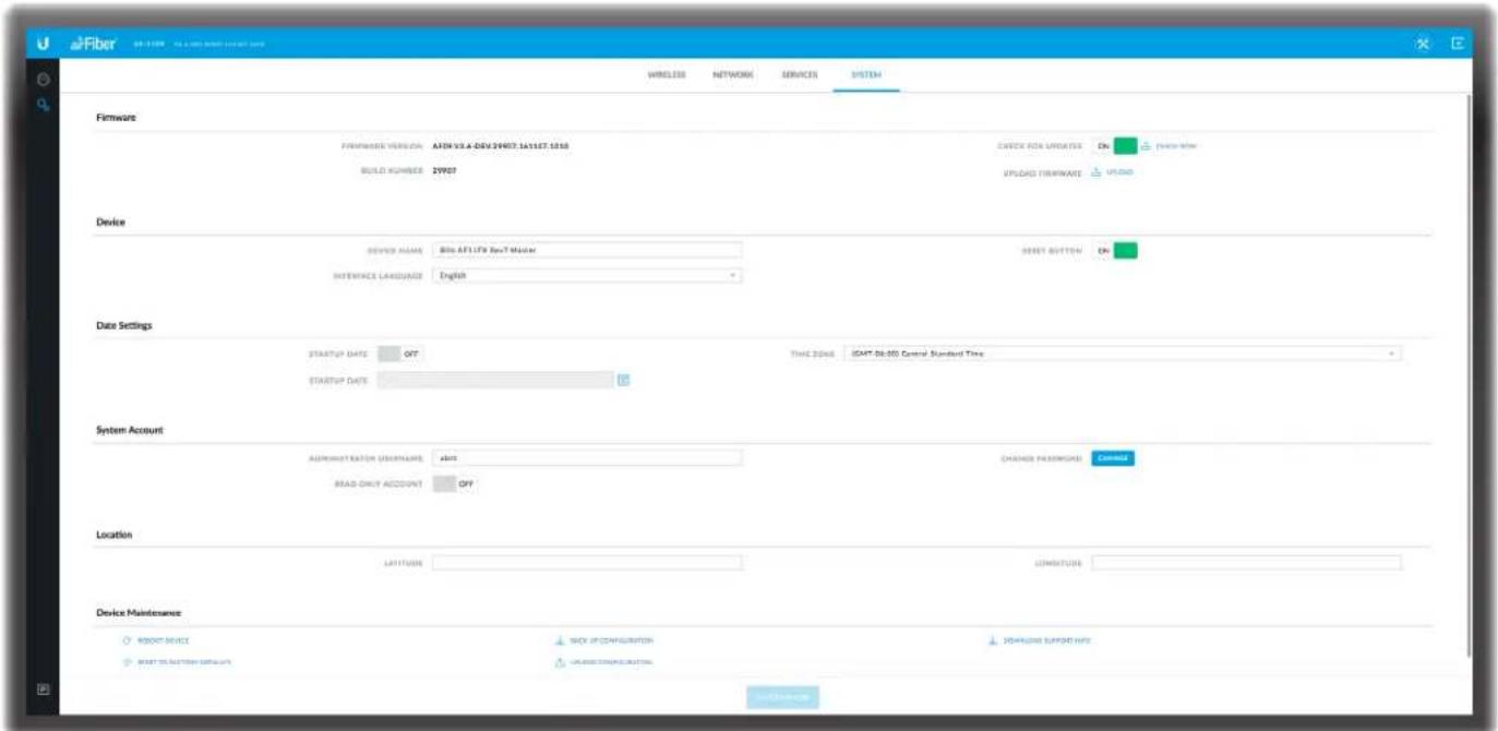
The System tab contains administrative options. This page enables the administrator to reboot the airFiber X radio, reset it to factory defaults, upload new firmware, back up or update the configuration, and configure the administrator account.
Test Changes To try the changes without saving them, click Test Changes. A new message appears. You have two options:
- Apply To immediately save your changes, click Apply.
- Discard To cancel your changes, click Discard. If you do not click Apply within 180 seconds (the countdown is displayed), the AF-11FX radio resumes its earlier configuration.
Revert Changes To cancel your changes, click
Revert Changes.
Save Changes To save your changes, click Save Changes.
Firmware Update
The controls in this section manage firmware maintenance.

Firmware Version Displays the current firmware version.
Build Number Displays the build number of the firmware version.
Check for Updates By default, the firmware automatically checks for updates. To manually check for an update, click Check Now.
Upload Firmware Click this button to update the airFiber X radio with new firmware.
The airFiber X radio firmware update is compatible with all configuration settings. The system configuration is preserved while the airFiber X radio is updated with a new firmware version. However, we recommend that you back up your current system configuration before updating the firmware.
This is a two-step procedure:
- Click Upload to locate the new firmware file. Select the file and click Open to upload the new firmware to the airFiber X radio.
- The Uploaded Firmware Version is displayed. Click Update to confirm, or click Discard if you do not wish to continue with the upload.
If the firmware update is in process, you can close the firmware update window, but this does not cancel the firmware update. Please be patient, as the firmware update routine can take three to seven minutes. You cannot access the airFiber X radio until the firmware update routine is completed.

WARNING: Do not power off, do not reboot, and do not disconnect the airFiber X radio from the power supply during the firmware update process as these actions will damage the airFiber X radio!
Device
The Device Name (host name) is the system-wide device identifier. The SNMP agent reports it to authorized management stations. The Device Name will be used in popular router operating systems, registration screens, and discovery tools.

Device Name Specifies the host name.
Interface Language Allows you to select the language displayed in the web management interface. English is the default language.
Reset Button To allow use of the airFiber X radio's physical reset button, check the box. To prevent an accidental reset to default settings, uncheck the box.

Note: You can reset the airFiber X radio to default settings via the airFiber Configuration Interface. Go to the System tab > Reset to Defaults.
Date Settings

Time Zone Specifies the time zone in relation to Greenwich Mean Time (GMT).
Startup Date When enabled, you are able to change the airFiber X radio's startup date.
- Startup Date Specifies the airFiber X radio's startup date. Click the Calendar icon or manually enter the date in the following format: 2-digit month/2-digit day/4-digit year. For example, for January 5, 2014, enter 01/05/2014 in the field.
System Accounts
You can change the administrator password to protect your device from unauthorized changes. We recommend that you change the default administrator password when initially configuring the device.

Administrator Username Specifies the name of the administrator.
Key icon Click this icon to change the administrator password.
- Current Password Enter the current password for the administrator account. It is required to change the Password or Administrator Username.
- New Password Enter the new password for the administrator account.
- Verify New Password Re-enter the new password for the administrator account.

Note: The password length is 8 characters maximum; passwords exceeding 8 characters will be truncated.
Read-Only Account Check the box to enable the read-only account, which can only view the Main tab. Configure the username and password to protect your device from unauthorized changes.
- Read-Only Account Name Specifies the name of the system user.
• Key icon Click this icon to change the read-only password. - New Password Enter the new password for the read-only account.
- Show Check the box to display the read-only password characters.
Location
After the on-board GPS determines the location of the airFiber X radio, its latitude and longitude are displayed. If the GPS does not have a fix on its location, then "Searching for Satellites" will be displayed.

Latitude The latitude of the airFiber X radio's location is displayed.
Longitude The longitude of the airFiber X radio's location is displayed.
Device Maintenance
The controls in this section manage the airFiber X radio maintenance routines: reboot device, reset to factory default settings, back up configuration, upload configuration, and download support information reports.

Reboot Device Initiates a full reboot cycle of the airFiber X radio. Reboot is the same as the hardware reboot, which is similar to the power-off and power-on cycle. The system configuration stays the same after the reboot cycle completes. Any changes that have not been applied are lost.
After the airFiber X radio reboots, the settings of the new configuration are displayed in the Wireless, Network, Advanced, Services, and System tabs of the airFiber Configuration Interface.
Reset to Factory Defaults Resets the airFiber X radio to the factory default settings. This option will reboot the airFiber X radio, and all factory default settings will be restored. We recommend that you back up your current system configuration before resetting the airFiber X radio to its defaults.
Back Up Configuration Click Download to download the current system configuration file. The airFiber X radio configuration is stored in a plain text file (.cfg file).
Upload Configuration Click Choose File to locate the new configuration file. Select the file and click Open. We recommend that you back up your current system configuration before uploading the new configuration.
Download Support Info This generates a support information file that the Ubiquiti support engineers can use when providing customer support. This file only needs to be generated at their request.
Chapter 8: System Tab airFiber AF-11FX User Guide
Chapter 9: Tools
Each tab of the airFiber Configuration Interface contains links to network administration and monitoring tools. To see these links, click the Tools®icon at the top right corner of the page. The available tools are:
• "Alignment" on page 37
• "Discovery" on page 38
• "Ping" on page 38
• "Traceroute" on page 38
- "airView" on page 38
Each tab of the airFiber Configuration Interface also contains the 📄log icon in the lower left corner of the page. Click this icon to display the system log (logging must enabled on the Services tab). For information on the Log feature, refer to:
• "Log" on page 40
Alignment
Use the Alignment tool to point and optimize the antenna in the direction of maximum link signal. The Antenna Alignment window is designed to refresh every 250 milliseconds.

Chain 0/1 (Actual/Ideal) Displays the absolute power level (in dBm) of the received signal for each chain.

Note: If "Overload" is displayed to indicate an overload condition, identify and eliminate any sources of strong in-band interference.
Remote Chain 0/1 Signal (Actual/Ideal) Displays the absolute power level (in dBm) of the received signal for each chain of the remote airFiber X radio.
Max Signal Displays the maximum signal strength (in dBm). To adjust the range of the Max Signal meter, use the slider or manually enter the new value. If you reduce the range, the color change will be more sensitive to signal fluctuations, indicating the offset of the maximum indicator value and the scale itself.
Discovery
The Device Discovery tool searches for all Ubiquiti devices on your network. The Search field automatically filters devices containing specified names or numbers as you enter them.
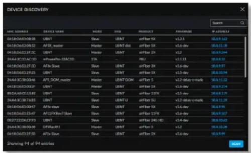
It reports the MAC Address, Device Name, Mode, SSID, Product type, Firmware version, and IP Address for each Ubiquiti device. To access a device configuration through its web management interface, click the device's IP address.
To refresh the window, click Scan.
Ping
You can ping other devices on the network directly from the airFiber X radio. The Ping tool uses ICMP packets to check the preliminary link quality and packet latency estimation between two network devices.
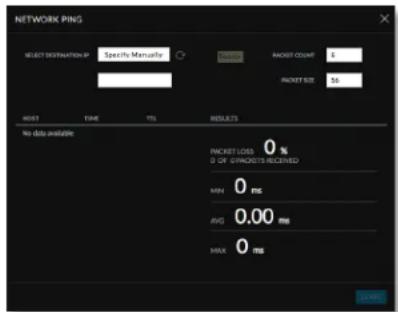
Network Ping
Select Destination IP You have two options:
- Select a remote system IP from the drop-down list, which is generated automatically.
- Select specify manually and enter the IP address in the field displayed below the option.
Packet Count Enter the number of packets to send for the ping test.
Packet Size Specify the size of the packet.
Start Click this button to start the test.
Packet loss statistics and latency time evaluation are displayed after the test is completed.
Traceroute
The Traceroute tool traces the hops from the airFiber X radio to a specified outgoing IP address. Use this tool to find the route taken by ICMP packets across the network to the destination host.

Destination Host Enter the IP address of the destination host.
Resolve IP Addresses Select this option to resolve the IP addresses symbolically rather than numerically.
Start Click this button to start the test.
Responses are displayed after the test is completed.
airView
Use the airView Spectrum Analyzer to analyze the noise environment of the radio spectrum and intelligently select the optimal frequency to install a PtP airFiber link.
There are two system requirements for the airView Spectrum Analyzer:
- Your system is connected to the device via Ethernet. Launching airView will terminate all wireless connections on the device.
- Java Runtime Environment 1.6 (or above) is required on your client machine to use airView.
On first use, the following window appears.

- Launch airView Spectrum Analyzer Click Launch airView Spectrum Analyzer to download the Java Network Launch Protocol (jnlp) file and complete the launch of airView.


Main View

Device Displays the device name, MAC (Media Access Control) address, and IP address of the device running airView.
Total RF Frames Displays the total number of Radio Frequency (RF) frames gathered since the start of the airView session or since the Reset All Data button was last clicked.
FPS Displays the total number of frames per second (FPS) gathered since the start of the airView session or since the Reset All Data button was last clicked. The wider the interval amplitude, the fewer the FPS will be gathered.
Reset All Data Click to reset all gathered data. Use this option to analyze the spectrum for another location or address.
File Menu
Click Exit to end the airView session.
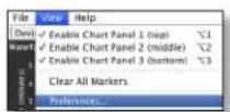
View Menu

Enable Chart Panel 1 (top) Displays the Waterfall or Channel Usage chart in Chart Panel 1, depending on which option you have selected in Preferences. This time-based graph shows the aggregate energy collected or channel usage for each frequency since the start of the airView session.
Enable Chart Panel 2 (middle) Displays the Waveform chart in Chart Panel 2. This time-based graph shows the RF signature of the noise environment since the start of the airView session. The energy color designates its amplitude. Cooler colors represent lower energy levels (with blue representing the lowest levels) in that frequency bin, and warmer colors (yellow, orange, or red) represent higher energy levels in that frequency bin.
Enable Chart Panel 3 (bottom) Displays the Real-time chart (traditional spectrum analyzer) in Chart Panel 3. Energy (in dBm) is shown in real time as a function of frequency.

Note: Energy is the power ratio in decibels (dB) of the measured power referenced to one milliwatt (mW).
Clear All Markers Resets all previously assigned markers. Markers are assigned by clicking a point, which corresponds with a frequency on the Real-time chart.
Preferences Changes airView settings, such as enabling or disabling charts and traces, or specifying the frequency interval.
Preferences
Select View > Preferences to display the Preferences - airView Spectrum Analyzer window.
Charts

Enable top chart Check the box to enable the top chart. Select the desired chart to display in the top chart panel on the main view. There are two options:
- Waterfall This time-based graph shows the aggregate energy collected for each frequency since the start of the airView session. The energy color designates its amplitude. Cooler colors represent lower energy levels (with blue representing the lowest levels) in that frequency bin, and warmer colors (yellow, orange, or red) represent higher energy levels in that frequency bin.
The Waterfall View's legend (top-right corner) provides a numerical guide associating the various colors to power levels (in dBm). The low end of that legend (left) is always adjusted to the calculated noise floor, and the high end (right) is set to the highest detected power level since the start of the airView session.
- Channel Usage For each channel, a bar displays a percentage showing the relative "crowdedness" of that specific channel. To calculate this percentage, the airView Spectrum Analyzer analyzes both the popularity and strength of RF energy in that channel since the start of an airView session.

Note: airFiber X radio channels are not related to Wi-Fi channels which are determined by IEEE standards. airFiber X radio channels are numbered consecutively starting with 0 and are 28 MHz in width.
Enable Waveform chart (middle) Check the box to enable the middle chart. This time-based graph shows the RF signature of the noise environment since the start of the airView session. The energy color designates its amplitude. Cooler colors represent lower energy levels (with blue representing the lowest levels) in that frequency bin, and warmer colors (yellow, orange, or red) represent higher energy levels in that frequency bin.
The spectral view over time will display the steady-state RF energy signature of a given environment.
Enable Real-time chart (bottom) Check the box to enable the bottom chart. This graph displays a traditional spectrum analyzer in which energy (in dBm) is shown in real time as a function of frequency. There are three traces in this view:
- Current (Yellow) Shows the real-time energy seen by the device as a function of frequency.
• Average (Green) Shows the running average energy across frequency.
• Maximum (Blue) Shows updates and maximum power levels across frequency.
Real-Time Traces

The following settings apply only to the Real-time chart:
Current Real-time Trace Check the Enable box to enable the real-time trace. When enabled, the yellow outline on the Real-time chart represents the real-time power level of each frequency. The refresh speed depends on the FPS.
Averages Trace Check the Enable box to enable the averages trace. When enabled, the averages trace is represented by the green area on the Real-time chart, which displays the average received power level data since the start of the airView session. To enable a shaded green area, check the Shaded Area box. To display only a green outline without the shaded area, uncheck the Shaded Area box.
Maximum Power Levels Trace Check the Enable box to enable the maximum power trace. When enabled, the maximum power trace is represented by the blue area on the Real-time chart, which displays the maximum received power level data since the start of the airView session. To enable a shaded blue area, check the Shaded Area box. To display only a blue outline without the shaded area, uncheck the Shaded Area box.
Frequency Range Select the amplitude of the frequency interval to be scanned from the Frequency Range drop-down list. Available frequencies are device-dependent. There are pre-defined ranges for the most popular bands. You can enter a custom range; select Custom Range from the Frequency Range drop-down list and enter the desired values in the Start and End fields.
Log
When logging is enabled (see "System Log" on page 31 for information on enabling the system log), this option lists all registered system events. By default, logging is not enabled.

Clear To delete all entries in the system log, click Clear.
Refresh To update the log content, click Refresh.
Appendix J: Specifications
| airFiber AF-11FX | |
| Dimensions 327 x 112 x 86 mm (12.87 x 4.41 x 3.39") | |
| Weight 2.26 kg (5.0 lb) | |
| RF Connectors (4) SMA Weatherproof, Two per Chain: TX 0, RX 0 (Chain 0) and TX 1, RX 1 (Chain 1)(2) N-Type Waterproof, One per Duplexer | |
| Power Supply 50V, 1.2A PoE Gigabit Adapter (Included) | |
| Power Method Passive Power over Ethernet or DC Power Block | |
| Supported Voltage Range 38-56VDC | |
| Mounting Enlarged airFiber X Mount | |
| Certifications FCC Part 101, ETSI EN 302 217 | |
| Operating Temperature -40 to 55°C (-40 to 131°F) | |
| AF-11FX Networking Interface | |
| Data Port (1) 10/100/1000 Ethernet Port | |
| Management Port (1) 10/100 Ethernet Port | |
| Auxiliary Port DC Power Block Input | |
| AF-11FX System | |
| Maximum Throughput | 1.2+ Gbps 1 |
| Maximum Range | 300+ km 1 |
| Encryption | 128-bit AES |
| OS | airFiber |
| Wireless Modes | SISO/MIMO |
| AF-11FX Radio | |
| Frequency Range | 10.7 - 11.7 GHz |
| Max. Conducted TX Power | 30 dBm(Dependent on Regulatory Region) |
| Frequency Accuracy | ±2.0 ppm |
| Channel Bandwidth | 3.5/5/7/10/14/20/28/30/40/50/56 MHz Selectable 2 |
| AF-11FX Suggested Max. TX Power | |
| 10x (1024QAM) | 18 dBm |
| 8x (256QAM) | 21 dBm |
| 6x (64QAM) | 24 dBm |
| 4x (16QAM) | 30 dBm |
| 2x (4QAM) | 30 dBm |
| 1x (QPSK) | 30 dBm |
Appendix J: Specifications airFiber AF-11FX User Guide
| AF-11FX Duplexer | |
| Low-Band Duplexer | Low Channel: 10.700 to 10.955 GHzHigh Channel: 11.200 to 11.445 GHz |
| High-Band Duplexer | Low Channel: 10.940 to 11.200 GHzHigh Channel: 11.440 to 11.700 GHz |
Appendix K: Safety Notices
- Read, follow, and keep these instructions.
- Heed all warnings.
- Only use attachments/accessories specified by the manufacturer.

WARNING: Do not use this product in location that can be submerged by water.

WARNING: Avoid using this product during an electrical storm. There may be a remote risk of electric shock from lightning.
Electrical Safety Information
-
Compliance is required with respect to voltage, frequency, and current requirements indicated on the manufacturer's label. Connection to a different power source than those specified may result in improper operation, damage to the equipment or pose a fire hazard if the limitations are not followed.
-
There are no operator serviceable parts inside this equipment. Service should be provided only by a qualified service technician.
-
This equipment is provided with a detachable power cord which has an integral safety ground wire intended for connection to a grounded safety outlet.
a. Do not substitute the power cord with one that is not the provided approved type. Never use an adapter plug to connect to a 2-wire outlet as this will defeat the continuity of the grounding wire.
b. The equipment requires the use of the ground wire as a part of the safety certification, modification or misuse can provide a shock hazard that can result in serious injury or death.
c. Contact a qualified electrician or the manufacturer if there are questions about the installation prior to connecting the equipment.
d. Protective earthing is provided by Listed AC adapter. Building installation shall provide appropriate short-circuit backup protection.
e. Protective bonding must be installed in accordance with local national wiring rules and regulations.
Appendix K: Safety Notices airFiber AF-11FX User Guide
Appendix L: Warranty
Limited Warranty
UBIQUITI NETWORKS, Inc ("UBIQUITI NETWORKS") warrants that the product(s) furnished hereunder (the "Product(s)") shall be free from defects in material and workmanship for a period of one (1) year from the date of shipment by UBIQUITI NETWORKS under normal use and operation. UBIQUITI NETWORKS' sole and exclusive obligation and liability under the foregoing warranty shall be for UBIQUITI NETWORKS, at its discretion, to repair or replace any Product that fails to conform to the above warranty during the above warranty period. The expense of removal and reinstallation of any Product is not included in this warranty. The warranty period of any repaired or replaced Product shall not extend beyond its original term.
Warranty Conditions
The above warranty does not apply if the Product:
(I) has been modified and/or altered, or an addition made thereto, except by Ubiquiti Networks, or Ubiquiti Networks' authorized representatives, or as approved by Ubiquiti Networks in writing;
(II) has been painted, rebranded or physically modified in any way;
(III) has been damaged due to errors or defects in cabling;
(IV) has been subjected to misuse, abuse, negligence, abnormal physical, electromagnetic or electrical stress, including lightning strikes, or accident;
(V) has been damaged or impaired as a result of using third party firmware;
(VI) has no original Ubiquiti MAC label, or is missing any other original Ubiquiti label(s); or
(VII) has not been received by Ubiquiti within 30 days of issuance of the RMA.
In addition, the above warranty shall apply only if: the product has been properly installed and used at all times in accordance, and in all material respects, with the applicable Product documentation; all Ethernet cabling runs use CAT5 (or above), and for outdoor installations, shielded Ethernet cabling is used, and for indoor installations, indoor cabling requirements are followed.

WARNING: Failure to properly ground your airFiber AF-11FX will void your warranty. (Please follow the instructions on "Install a Ground Wire" on page 5 for installation of the ground wires.)
Returns
No Products will be accepted for replacement or repair without obtaining a Return Materials Authorization (RMA) number from UBIQUITI NETWORKS during the warranty period, and the Products being received at UBIQUITI NETWORKS' facility freight prepaid in accordance with the RMA process of UBIQUITI NETWORKS. Products returned without an RMA number will not be processed and will be returned freight collect or subject to disposal. Information on the RMA process and obtaining an RMA number can be found at: www.ubnt.com/support/warranty.
Disclaimer
EXCEPT FOR ANY EXPRESS WARRANTIES PROVIDED HEREIN, UBIQUITI NETWORKS, ITS AFFILIATES, AND ITS AND THEIR THIRD PARTY DATA, SERVICE, SOFTWARE AND HARDWARE PROVIDERS HEREBY DISCLAIM AND MAKE NO OTHER REPRESENTATION OR WARRANTY OF ANY KIND, EXPRESS, IMPLIED OR STATUTORY, INCLUDING, BUT NOT LIMITED TO, REPRESENTATIONS, GUARANTEES, OR WARRANTIES OF MERCHANTABILITY, ACCURACY, QUALITY OF SERVICE OR RESULTS, AVAILABILITY, SATISFACTORY QUALITY, LACK OF VIRUSES, QUIET ENJOYMENT, FITNESS FOR A PARTICULAR PURPOSE AND NON-INFRINGEMENT AND ANY WARRANTIES ARISING FROM ANY COURSE OF DEALING, USAGE OR TRADE PRACTICE IN CONNECTION WITH SUCH PRODUCTS AND SERVICES. BUYER ACKNOWLEDGES THAT NEITHER UBIQUITI NETWORKS NOR ITS THIRD PARTY PROVIDERS CONTROL BUYER'S EQUIPMENT OR THE TRANSFER OF DATA OVER COMMUNICATIONS FACILITIES, INCLUDING THE INTERNET, AND THAT THE PRODUCTS AND SERVICES MAY BE SUBJECT TO LIMITATIONS, INTERRUPTIONS, DELAYS, CANCELLATIONS AND OTHER PROBLEMS INHERENT IN THE USE OF COMMUNICATIONS FACILITIES. UBIQUITI NETWORKS, ITS AFFILIATES AND ITS AND THEIR THIRD PARTY PROVIDERS ARE NOT RESPONSIBLE FOR ANY INTERRUPTIONS, DELAYS, CANCELLATIONS, DELIVERY FAILURES, DATA LOSS, CONTENT CORRUPTION, PACKET LOSS, OR OTHER DAMAGE RESULTING FROM ANY OF THE FOREGOING. In addition, UBIQUITI NETWORKS does not warrant that the operation of the Products will be error-free or that operation will be uninterrupted. In no event shall UBIQUITI NETWORKS be responsible for damages or claims of any nature or description relating to system performance, including coverage, buyer's selection of products (including the Products) for buyer's application and/or failure of products (including the Products) to meet government or regulatory requirements.
Limitation of Liability
EXCEPT TO THE EXTENT PROHIBITED BY LOCAL LAW, IN NO EVENT WILL UBIQUITI OR ITS SUBSIDIARIES, AFFILIATES OR SUPPLIERS BE LIABLE FOR DIRECT, SPECIAL, INCIDENTAL, CONSEQUENTIAL OR OTHER DAMAGES (INCLUDING LOST PROFIT, LOST DATA, OR DOWNTIME COSTS), ARISING OUT OF THE USE, INABILITY TO USE, OR THE RESULTS OF USE OF THE PRODUCT, WHETHER BASED IN WARRANTY, CONTRACT, TORT OR OTHER LEGAL THEORY, AND WHETHER OR NOT ADVISED OF THE POSSIBILITY OF SUCH DAMAGES.
Note
Some countries, states and provinces do not allow exclusions of implied warranties or conditions, so the above exclusion may not apply to you. You may have other rights that vary from country to country, state to state, or province to province. Some countries, states and provinces do not allow the exclusion or limitation of liability for incidental or consequential damages, so the above limitation may not apply to you. EXCEPT TO THE EXTENT ALLOWED BY LOCAL LAW, THESE WARRANTY TERMS DO NOT EXCLUDE, RESTRICT OR MODIFY, AND ARE IN ADDITION TO, THE MANDATORY STATUTORY RIGHTS APPLICABLE TO THE LICENSE OF ANY SOFTWARE (EMBEDDED IN THE PRODUCT) TO YOU. The United Nations Convention on Contracts for the International Sale of Goods shall not apply to any transactions regarding the sale of the Products.
Appendix M: Compliance Information
Installer Compliance Responsibility
Devices must be professionally installed and it is the professional installer's responsibility to make sure the device is operated within local country regulatory requirements.
It is also the responsibility of the professional installer to obtain the proper licensing through their respective license coordinators for this product.
Operating License
The AF-11FX operates in bands that require a license in most countries.

Note: In most countries it is illegal to operate the AF-11FX without a license from the national or regional regulating authority.
FCC
The AF-11FX has been verified by Ubiquiti Networks, Inc. as being in compliance with the requirements of the rules of the Federal Communications Commission (FCC), 47 C.F.R. Part 101, and may not be operated without a station license. In the United States such licenses are issued by the FCC to entities other than agencies of the United States government. Federal government agencies are licensed by the National Telecommunications and Information Administration (NTIA) acting upon the recommendation of the Interdepartment Radio Advisory Committee (IRAC).
Frequency Plan
The AF-11FX frequency plan is compliant with FCC and IC specifications, as listed in the following table:
| Band | Frequency Range (GHz) | Bandwidth (MHz) | T/R Spacing (MHz) | Reference |
| 11 GHz | 10.7 - 11.7 | 3.5, 5, 10, 30, 40, 80 | 490, 500 | FCC Part 101-147 |
RF Exposure Warning
The antennas used for this transmitter must be installed to provide a separation distance of at least 270 cm from all persons and must not be located or operating in conjunction with any other antenna or transmitter.
Australia and New Zealand

Warning: This is a Class A product. In a domestic environment this product may cause radio interference in which case the user may be required to take adequate measures.
CE Marking
CE marking on this product represents the product is in compliance with all directives that are applicable to it.

Compliance Documentation
For detailed compliance information, refer to the AF-11FX Declaration of Conformity document, available at: www.ubnt.com/compliance/
RoHS/WEEE Compliance Statement

English
European Directive 2012/19/EU requires that the equipment bearing this symbol on the product and/or its packaging must not be disposed of with unsorted municipal waste. The symbol indicates that this product should be disposed of separately from regular household waste streams. It is your responsibility to dispose of this and other electric and electronic equipment via designated collection facilities appointed by the government or local authorities. Correct disposal and recycling will help prevent potential negative consequences to the environment and human health. For more detailed information about the disposal of your old equipment, please contact your local authorities, waste disposal service, or the shop where you purchased the product.
Deutsch
Appendix N: Declaration of Conformity
| Česky [Czech] | UBIQUITI NETWORKS tímto prohlašuje, že toto UBIQUITI NETWORKS zařízeni, je ve shod se základními požadavky a dalšími příslušnými ustanoveními směrnice 1999/5/ES. |
| Dansk [Danish] | Hermed, UBIQUITI NETWORKS, erklærer at denne UBIQUITI NETWORKS enhed, er i overensstemmelse med de væsentlige krav og øvrige relevante krav i direktiv 1999/5/EF. |
| Nederlands [Dutch] | Hierbij verklaart UBIQUITI NETWORKS, dat deze UBIQUITI NETWORKS apparaat, in overeenstemming is met de essentiële eisen en de andere relevante bepalingen van richtlijn 1999/5/EG. |
| English | Hereby, UBIQUITI NETWORKS, declares that this UBIQUITI NETWORKS device, is in compliance with the essential requirements and other relevant provisions of Directive 1999/5/EC. |
| Eesti [Estonian] | Käesolevaga UBIQUITI NETWORKS kinnitab, et antud UBIQUITI NETWORKS seade, on vastavus olulistele nõuetele ja teistele asjakohastele sätetele direktiivi 1999/5/EÜ. |
| Suomi [Finnish] | Täten UBIQUITI NETWORKS vakuuttaa, että tämä UBIQUITI NETWORKS laite, on yhdenmukainen olennaisten vaatimusten ja muiden sitä koskevien direktiivin 1999/5/EY. |
| Français [French] | Par la présente UBIQUITI NETWORKS déclare que l'appareil UBIQUITI NETWORKS, est conforme aux exigences essentielles et aux autres dispositions pertinentes de la directive 1999/5/CE. |
| Deutsch [German] | Hiermit erklärt UBIQUITI NETWORKS, dass sich dieses UBIQUITI NETWORKS Gerät, in Übereinstimmung mit den grundlegenden Anforderungen und den anderen relevanten Vorschriften der Richtlinie 1999/5/EG befindet. |
| Ελληνική [Greek] | Δια του παρόντος, UBIQUITI NETWORKS, δηλώνει ότι αυτή η συσκευή UBIQUITI NETWORKS, είναι σε συμμόρφωση με τις βασικές απαιτήσεις και τις λοιπές σχετικές διατάξεις της οδηγίας 1995/5/EK. |
| Magyar [Hungarian] | Ezennel UBIQUITI NETWORKS kijelenti, hogy ez a UBIQUITI NETWORKS készülék megfelel az alapvető követelményeknek és más vonatkozó 1999/5/EK irányely rendelkezéseit. |
| Íslenska [Icelandic] | Hér, UBIQUITI NETWORKS, því yfir að þetta UBIQUITI NETWORKS tæki er í samræmi við grunnkröfur og önnur viðeigandi ákvæði tilskipun 1999/5/EB. |
| Italiano [Italian] | Con la presente, UBIQUITI NETWORKS, dichiara che questo dispositivo UBIQUITI NETWORKS, è conforme ai requisiti essenziali ed alle altre disposizioni pertinenti della direttiva 1999/5/CE. |
| Latviski [Latvian] | Ar šo, UBIQUITI NETWORKS, deklare, ka UBIQUITI NETWORKS ierice, ir saskaņā ar bütiskajām prasibām un citiem attiecīgiem noteikumiem Direktivā 1999/5/EK. |
| Lietuviškai [Lithuanian] | UBIQUITI NETWORKS deklaruoja, kad šis UBIQUITI NETWORKS jrenginys atitinka esminius reikalavimus ir kitas 1999/5/EB Direktyvos nuostatas. |
| Malti [Maltese] | Hawnhekk, UBIQUITI NETWORKS, tiddikjara li dan il-mezz UBIQUITI NETWORKS huwa konformi mar-rekwiziti essenzjali u dispožizzjonijiet rilevanti ohrajn ta 'Direttiva 1999/5/KE. |
| Norsk [Norwegian] | Herved UBIQUITI NETWORKS, erklærer at denne UBIQUITI NETWORKS enheten, er i samsvar med de grunnleggende kravene og andre relevante bestemmelser i direktiv 1999/5/EF. |
| Polski [Polish] | Niniejszym, Ubiquiti Networks, oświadcza, że urządzenie UBIQUITI NETWORKS, jest zgodny z zasadniczymi wymaganiami oraz pozostałymi stosownymi postanowieniami Dyrektywy 1999/5/WE. |
| Português [Portuguese] | UBIQUITI NETWORKS declara que este dispositivo UBIQUITI NETWORKS, está conforme com os requisitos essenciais e outras disposições da Directiva 1999/5/CE. |
| Română [Romanian] | Prin prezenta, UBIQUITI NETWORKS declară că acest dispozitiv UBIQUITI NETWORKS este în conformitate cu cerințele esențiale și alte prevederi relevante ale Directivei 1999/5/CE. |
| Slovensky [Slovak] | Týmto UBIQUITI NETWORKS, prehlasuje, že toto UBIQUITI NETWORKS zariadenie, je v súlade so základnými požiadavkami a dálšími relevantnými ustanoveniami smernice 1999/5/ES. |
| Español [Spanish] | Por medio de la presente UBIQUITI NETWORKS declara que este dispositivo UBIQUITI NETWORKS, cumple con los requisitos esenciales y cualesquiera otras disposiciones aplicables o exigibles de la Directiva 1999/5/CE. |
| Svenska [Swedish] | Härmed UBIQUITI NETWORKS, intygar att denna UBIQUITI NETWORKS enhet är i överensstämmelse med de väsentliga egenskapskrav och övriga relevanta bestämmelser som framgår av direktiv 1999/5/EG. |
Appendix O: Contact Information
Ubiquiti Networks Support
Ubiquiti Support Engineers are located around the world and are dedicated to helping customers resolve software, hardware compatibility, or field issues as quickly as possible. We strive to respond to support inquiries within a 24-hour period.
Ubiquiti Networks, Inc.
685 Third Avenue, 27th Floor
New York, New York 10017
www.ubnt.com
Online Resources
Support: ubnt.link/airFiber-Support
Community: community.ubnt.com/airfiber
Downloads: downloads.ubnt.com/airfiber

www.ubnt.com
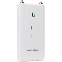

- AIRFIBER® 11FX
- TABLE OF CONTENTS
- CHAPTER 1: OVERVIEW....1
- CHAPTER 2: INSTALLATION ....5
- CHAPTER 3: NAVIGATION ..... 15
- CHAPTER 4: DASHBOARD ....17
- CHAPTER 5: WIRELESS TAB....21
- CHAPTER 6: NETWORK TAB ...... 25
- CHAPTER 7: SERVICES TAB....29
- CHAPTER 8: SYSTEM TAB....33
- CHAPTER 9: TOOLS....37
- APPENDIX J: SPECIFICATIONS....41
- APPENDIX K: SAFETY NOTICES....43
- APPENDIX L: WARRANTY 45
- APPENDIX M: COMPLIANCE INFORMATION 47
- CHAPTER 1: OVERVIEW
- INTRODUCTION
- AIRFIBER CONFIGURATION INTERFACE SYSTEM REQUIREMENTS
- LEDS
- SIGNAL LEDS
- CHAPTER 2: INSTALLATION
- INSTALLATION REQUIREMENTS
- OTHER REQUIREMENTS
- WARNING: FAILURE TO PROPERLY GROUND YOUR AIRFIBER X RADIO WILL VOID YOUR WARRANTY
- INSTALLATION OVERVIEW
- INSTALLING THE DUPLEXER FOR SISO MODE
- CHAPTER 2: INSTALLATION AIRFIBER AF-11FX USER GUIDE
- INSTALLING AN OPTIONAL DUPLEXER (MIMO MODE)
- CONNECTING POWER OVER ETHERNET
- AIRFIBER CONFIGURATION
- HARDWARE INSTALLATION
- INSTALL A GROUND WIRE
- MOUNT TO THE AIRFIBER X ANTENNA
- CONNECTING DATA
- CONNECTING POWER
- POWER OVER ETHERNET
- DC POWER
- SURGE PROTECTION
- ALIGNMENT
- TIPS
- ESTABLISHING A LINK
- INSTALLER COMPLIANCE RESPONSIBILITY
- CHAPTER 3: NAVIGATION
- ACCESSING THE AIRFIBER CONFIGURATION INTERFACE
- INTERFACE PAGES
- CONFIGURATION INTERFACE NOTIFICATIONS
- PENDING CHANGES
- PRODUCT VERIFICATION
- CHAPTER 4: DASHBOARD
- LINK STATUS
- LOCAL
- REMOTE
- SIGNAL STRENGTH
- DEVICE
- ETHERNET
- CHAPTER 5: WIRELESS TAB
- BASIC WIRELESS SETTINGS
- FREQUENCY SETTINGS
- WIRELESS SECURITY
- ADVANCED WIRELESS SETTINGS
- CHAPTER 6: NETWORK TAB
- MANAGEMENT NETWORK SETTINGS
- DATA PORT ETHERNET SETTINGS
- ETHERNET CARRIER DROP SETTINGS
- CHAPTER 7: SERVICES TAB
- REVERT CHANGES
- PING WATCHDOG
- SNMP AGENT
- WEB SERVER
- SSH SERVER
- TELNET SERVER
- NTP CLIENT
- DYNAMIC DNS
- SYSTEM LOG
- DEVICE DISCOVERY
- CHAPTER 8: SYSTEM TAB
- FIRMWARE UPDATE
- DATE SETTINGS
- SYSTEM ACCOUNTS
- LOCATION
- DEVICE MAINTENANCE
- CHAPTER 9: TOOLS
- DISCOVERY
- PING
- NETWORK PING
- TRACEROUTE
- AIRVIEW
- MAIN VIEW
- FILE MENU
- VIEW MENU
- PREFERENCES
- CHARTS
- REAL-TIME TRACES
- LOG
- APPENDIX J: SPECIFICATIONS
- APPENDIX K: SAFETY NOTICES
- ELECTRICAL SAFETY INFORMATION
- APPENDIX L: WARRANTY
- LIMITED WARRANTY
- WARRANTY CONDITIONS
- RETURNS
- DISCLAIMER
- LIMITATION OF LIABILITY
- NOTE
- APPENDIX M: COMPLIANCE INFORMATION
- OPERATING LICENSE
- FCC
- FREQUENCY PLAN
- RF EXPOSURE WARNING
- AUSTRALIA AND NEW ZEALAND
- CE MARKING
- COMPLIANCE DOCUMENTATION
- ROHS/WEEE COMPLIANCE STATEMENT
- ENGLISH
- DEUTSCH
- APPENDIX O: CONTACT INFORMATION
- UBIQUITI NETWORKS SUPPORT
- ONLINE RESOURCES
Brand : Ubiquiti Networks
Model : airFiber 11FX AF-11FX
Category : Wi-Fi repeater