
Studio Force II 48 - Lighting Chrome-Q - Free user manual and instructions
Find the device manual for free Studio Force II 48 Chrome-Q in PDF.


| Product Type | LED Lighting Fixture |
| Brand | Chrome-Q |
| Model | Studio Force II 48 |
| Dimensions (W x H x D) | 48 x 8 x 10 inches (122 x 20 x 25 cm) |
| Weight | 28 lbs (12.7 kg) |
| Power Supply | AC 100-240V, 50/60Hz |
| Power Consumption | 480W max |
| Light Source | 48 x 10W RGBW LEDs |
| Color Range | RGBW color mixing, 16.7 million colors |
| Beam Angle | 25° (interchangeable) |
| Control Protocol | DMX512, RDM, Master/Slave, Standalone |
| DMX Channels | 4/8/10/12 channels selectable |
| Housing Material | Aluminum alloy, steel |
| Cooling System | Silent fan, passive heat sink |
| IP Rating | IP20 (indoor use only) |
| Mounting Options | Floor stand, truss clamp, wall mount |
| Accessories Included | Power cable, DMX cable, mounting bracket, user manual |
| Safety Certifications | CE, RoHS |
| Maintenance | Wipe with dry cloth; avoid solvents |
| Spare Parts Availability | LED modules, power supply, control boards available |
| Repair Service | Authorized service centers worldwide |
Frequently Asked Questions - Studio Force II 48 Chrome-Q
User questions about Studio Force II 48 Chrome-Q
0 question about this device. Answer the ones you know or ask your own.
Ask a new question about this device
Download the instructions for your Lighting in PDF format for free! Find your manual Studio Force II 48 - Chrome-Q and take your electronic device back in hand. On this page are published all the documents necessary for the use of your device. Studio Force II 48 by Chrome-Q.
USER MANUAL Studio Force II 48 Chrome-Q
natural_image
Three black optical transducers with rainbow-colored grating, arranged in a row (no text or symbols visible)
Chroma-Q®
BRILLIANT SOLUTIONS
Part Number: CHSF2V12, CHSF2V12LR, CHSF2V12W,
CHSF2V48, CHSF2V48LR, CHSF2V48W,
CHSF2V72, CHSF2V72LR, CHSF2V72W
(Model: 652-1150, 652-1650, 652-1250,
641-4000, 641-4100, 641-4500,
641-5000, 641-5100, 641-5500)
Software Version 1.4
Manual: 641-0906 V1.2
Warranty Statement
Chroma-Q warrants to the original purchaser, with proof of purchase, that its delivered products shall be free from defects in material and workmanship under normal use for a period of 24 months from date of shipment.
Chroma-Q will repair, or at its option, provide an equivalent item or replace, the defective product during the stated warranty period. This warranty applies only to the repair or replacement of the product and only when the product is properly handled, installed and maintained according to Chroma-Q instructions. This warranty excludes defects resulting from improper handling, storage, installation, acts of God, fire, vandalism or civil disturbances. Purchaser must notify Chroma-Q in writing within 14 days of noticing the defect. This warranty excludes field labor or service charges related to the repair or replacement of the product.
The warranty contained herein shall not extend to any finished goods or spare parts from which any serial number has been removed or which have been damaged or rendered defective (a) as a result of normal wear and tear, willful or accidental damage, negligence, misuse or abuse; (b) due to water or moisture, lightning, windstorm, abnormal voltage, harmonic distortion, dust, dirt, corrosion or other external causes; (c) by operation outside the specifications contained in the user documentation; (d) by the use of spare parts not manufactured or sold by Chroma-Q or by the connection or integration of other equipment or software not approved by Chroma-Q unless the Customer provides acceptable proof to Chroma-Q that the defect or damage was not caused by the above; (e) by modification, repair or service by anyone other than Chroma-Q, who has not applied for and been approved by Chroma-Q to do such modification, repair or service unless the Customer provides acceptable proof to Chroma-Q that the defect or damage was not caused by the above; (f) due to procedures, deviating from procedures specified by Chroma-Q or (g) due to failure to store, install, test, commission, maintain, operate or use finished goods and spare parts in a safe and reasonable manner and in accordance with Chroma-Q's instructions (h) by repair or replacement of engines without factory training.
The warranty contained herein shall not apply to finished goods or spare parts which are sold “as is”, as “second-hand”, as “used”, as “demo” or under similar qualifications or to Consumables (“Consumables” is defined as any part(s) of goods or part(s) for use with goods, which part(s) of goods or part(s) for use with goods are consumed during the operation of the goods and which part(s) of goods or part(s) for use with goods require replacement from time to time by a user such as, but not limited to, light bulbs).
The warranty contained herein shall not apply, unless the total purchase price for the defective finished goods or spare parts has been paid by the due date for payment.
The warranty contained herein applies only to the original purchaser and are not assignable or transferable to any subsequent purchaser or end-user.
This warranty is subject to the shipment of the goods, within the warranty period, to the Chroma-Q warranty returns department, by the purchaser, at the purchaser's expense. If no fault is found, Chroma-Q will charge the purchaser for the subsequent return of the goods.
Chroma-Q reserves the right to change the warranty period without prior notice and without incurring obligation and expressly disclaims all warranties not stated in this limited warranty.
Disclaimer
The information contained herein is offered in good faith and is believed to be accurate. However, because conditions and methods of use of our products are beyond our control, this information should not be used in substitution for customer's tests to ensure that Chroma-Q products are safe, effective, and fully satisfactory for the intended end use. Suggestions of use shall not be taken as inducements to infringe any patent. Chroma-Q sole warranty is that the product will meet the sales specifications in effect at the time of shipment. Your exclusive remedy for breach of such warranty is limited to refund of purchase price or replacement of any product shown to be other than as warranted.
Chroma-Q reserves the right to change or make alteration to devices and their functionality without notice due to our ongoing research and development.
The Chroma-Q Studio Force II ^™ has been designed specifically for the lighting industry. Regular maintenance should be performed to ensure that the products perform well in the entertainment environment.
If you experience any difficulties with any Chroma-Q products please contact your selling dealer. If your selling dealer is unable to help please contact support@chroma-q.com. If the selling dealer is unable to satisfy your servicing needs, please contact the following, for full factory service:
Outside North America: North America:
Tel: +44 (0)1494 446000 Tel: 416-255-9494
Fax: +44 (0)1494 461024 Fax: 416-255-3514
support@chroma-q.com support@chroma-q.com
For further information please visit the Chroma-Q website at www.chroma-q.com.
Chroma-Q and Studio Force II ^™ are trademarks, for more information on this visit
http://www.chroma-q.com/trademarks.asp. The rights and ownership of all trademarks are recognized.
Important Notice:
As per the requirements in the Occupational Safety and Health Administration standards for product approval, please refer to the OSHA web pages http://www.osha.gov/dts/otpca/nrtl/ for information on the list of Nationally Recognized Testing Laboratories (NRTLs) and the scope of recognition.


WARNING!
Read the safety precautions in this section before installing, powering, operating or servicing this product.
The following symbols are used to identify important safety information on the product and in this document:

Warning! Safety Hazard. Risk of severe injury or death.

Warning! Fire Hazard.
Warning! Hazardous Voltage. Risk of severe lethal electric shock.

Warning! Refer to User manual.
Warning!
Read the user manual before installing and operating the Chroma-Q Studio Force II ^TM . For future reference, keep and use the manual.
Safety precautions given in user manual must be followed at all times and the manuals of all the devices you connect it to. Observe all the warnings printed on product and in manuals. Make sure whoever is involved in working on or using the Chroma-Q Studio Force II ^TM has carefully read and understood all the safety precautions and listed warnings.
- Install, connect, operate and service devices only as described in this manual and in connected devices' manuals and only in accordance with local laws and regulations. All Chroma-Q manuals are available for download from www.chroma-q.com.
- Chroma-Q Studio Force II ^TM does not have user-serviceable parts. Refer any operation not described in this manual to support@chroma-q.com.
If you experience difficulties with any Chroma-Q products please contact your local dealer. If your local dealer is unable to help then please contact support@chroma-q.com.
If you are having trouble finding what you are looking for on our website, then contact our Chroma-Q marketing department by sending an email to marketing@chroma-q.com.
PROTECTION FROM ELECTRIC SHOCK
- Use only the cables specified in this manual and on the Chroma-Q website at www.chroma-q.com to interconnect devices in the installation. If the specified cables are not long enough for an intended cable run, consult Chroma-Q for assistance in finding or creating a safe alternative solution.
- Provide a means of locking out AC mains power that allows power to the installation to be shut down and made impossible to reapply, even accidentally, during work on the installation.
- Shut down power to the installation during service and when it is not in use.
- Before applying power to the installation, check that all power distribution equipment and cables are in perfect condition and rated for the current requirements of all connected devices.
- Isolate the installation from power immediately if any product, power cable or power plug is in any way damaged, defective or wet, or if it shows signs of overheating.
- Do not immerse a Chroma-Q Studio Force II ^TM fixture in water or expose it to high-pressure water jets.
PROTECTION FROM BURNS AND FIRE
- The Studio Force II ^TM is designed to be cooled by forced air convection. Provide free airflow around the fixture and a minimum clearance of 10 mm (0.4 in.) in all directions.
- Do not operate the Studio Force II ^TM if the ambient operating temperature exceeds 40°C (104°F).
- Do not modify the Studio Force II ^TM in any way not described in this manual or install other than genuine Chroma-Q parts. Use only accessories approved by Chroma-Q.
PROTECTION FROM INJURY
- Ensure that the installation hardware and supporting surface or structure can hold at least 10 times the weight of all the devices they support.
- Block access below the work area and work from a stable platform whenever installing, servicing or moving the Studio Force II ^TM .
- As soon as work is completed, check that all hardware and components are securely fastened to supporting structures.
- Make sure there are no flammable materials close to the product during operation.
- Make sure the power cord is not crimped or damaged.
- Avoid direct eye exposure to the light source while the product is on.
- Never try to repair the product. Repairs carried out by unskilled people can lead to damage or malfunction and/or invalidate your warranty. Please contact the nearest authorized dealer or contact support@chroma-q.com.

Keep this User Manual for future consultation. If this product is used by another user, be sure that they also receive this document.
Contents
Contents....5
- Product overview....7
- Operation....8
2.1. Unpacking the units....8
2.2. Cabling 8
2.3. Mounting....9
2.4. Optics 9
Cyc & Border Lens....9
2.5. Control....10
2.6. Main Menu....11
Configuration option buttons....12
DMX 12
- Mode 12
3.1. Mode Select Options 13
3.2. Mode Options 15
3.3. Grouping Options 16
3.4. Pixel ordering Options 17
3.5. DMX Footprints....17
- Set up Menu 18
4.1. DMX Data....19
4.2. Fan Speed....19
4.3. Rotate Display 19
4.4. PWM Frequency....20
4.5. DMX Lost....20
4.6. Lock feature....21
4.7. Reset and Factory Defaults 22
4.8. Upload Engine 23
4.9. FW Version....23
4.10. DMX Source 23
4.11. Engine Temp 23
- Look Store 24
- Thermal Performance....25
- Troubleshooting....25
- Maintenance....25
- Specification 26
9.1. Technical specifications....26
9.2. Technical Drawings 27
Studio Force II 72....27
Studio Force II 48....28
Studio Force II 12....29
- Menu Tree 30
- DMX Map 31
11.1. Studio Force II DMX map for RGBW Control Mode: 31
11.2. Studio Force II DMX map for RGB Control Mode: 31
11.3. Studio Force II DMX map for HSi Control Mode: 32
11.4. Studio Force II DMX map for KHi Control Mode: 32
11.5. Studio Force II DMX map for Cine-Q i-KH-RGBW Control Mode....33
11.6. Studio Force II DMX map for Cine-Q i-KH-RGBW 16bit Control Mode ....34
11.7. Studio Force II DMX map group modes 35
11.8. Studio Force II DMX map Control channel 35
- RDM FUNCTIONS 36
12.1. FREQUENCY, FAN_SPEED and GROUPING 36
1. Product overview
The Chroma-Q Studio Force II ^TM LED batten range is a powerful lineup of professional lighting industry. With up to ≈36,000/ Studio Force II ^TM 72, ≈24,000/ Studio Force II ^TM 48, ≈6,500/ Studio Force II ^TM 12 hot lumens output, these super bright fixtures are specifically designed for TV Broadcast and film applications but also performs particularly well in other situations demanding high quality tunable white light such as touring key lights, exhibitions, corporate events and theatre lighting.
Optional slide-in "Cyc Light" and "Border Light" optical lens accessories are available to adjust the light output to suit a wide range of applications.
The Chroma-Q Studio Force II ^TM lighting fixture is designed for professional indoor entertainment lighting. The fixture can be wall or floor mounted with the adjustable quick-release end-plate fixing system. For hung bar or truss mounting, additional bar clamp hardware is required.
The Studio Force II ^TM features integrated power supplies and can be operated as a stand-alone unit or be remotely controlled through ANSI E1.11 USITT DMX 512-A protocol via a cable or a Lumen Radio wireless connection (when using the optional RF module).
The Studio Force II ^TM is available in three lengths, the Studio Force II ^TM V72 model which features a total of 24 high output cells (or pixels), the Studio Force II ^TM V48 model which features a total of 16 high output cells (or pixels) and the Studio Force II ^TM V12 model which features a total of 4 high output cells (or pixels). Each cell provides a homogenized output with no unsightly color shadowing like fixtures using traditional individual light emitters.
The control options incorporate a choice of KHi (Kelvin, Hue and intensity), Cine-Q (Intensity, Kelvin, Hue, Red, Green, Blue, White and Crossfade between KH and RGBW), RGBW (Red, Green, Blue, and White), RGB (Red, Green, and Blue), HSi (Hue, Saturation and intensity) and control modes.
An extra control parameter channel can be added to any of the modes, the channel will be placed as the last parameter of the fixture.
The product's robust extruded aluminum construction houses a discreet cable management system. Additional protection is built around the lenses for a truly road proof fixture.
2. Operation
2.1. Unpacking the units
The Studio Force II package includes the Studio Force II fixture, power cord, preinstalled mounting bracket and a Quick Start Guide. It is strongly recommended that original packaging is kept, for the ease of transportation.
2.2. Cabling
The Studio Force II ^TM utilizes Neutrik powerCON true1 connectors for power input and through connections. The DMX control data input and through connections are via two Neutrik XLR 5-pin male and female connectors. The chassis are ground bonded.
XLR-5 Pinout: Power and Data Input Location
| Pin# | Function |
| 1 | Ground (Screen) |
| 2 | Data Minus |
| 3 | Data Plus |
| 4 | Spare Data Minus |
| 5 | Spare Data Plus |
Table 1 (XLR PIN)

natural_image
Close-up of a black electronic component with attached wires and connectors (no visible text or symbols)Figure 1 (Connection)
Power Cable Pinout:
| International Colour Code | Connections | North American Colour Code | Connections |
| Green and Yellow | Earth (E) | Green | Ground (Green) |
| Blue | Neutral (N) | White | Neutral (Silver) |
| Brown | Live (L) | Black | Hot (Gold) |
Table 2 (Power Cable Colour Code)
Important Notice:
The use of an optical splitter for DMX signal distribution is highly recommended when several fixtures are not plugged into the same power source.
Maximum Number of fixtures connected in a series:
Important Notice: Actual number of fixtures connected in series may be lower, based on your branch circuit inrush rating.
| Fixture | Wattage | @110V | @220V |
| SF II 72 | 800W | 2 x SF II 72 | 4 x SF II 72 |
| SF II 48 | 550W | 3 x SF II 48 | 6 x SF II 48 |
| SF II 12 | 150W | 10 x SF II 12 | 20 x SF II 12 |
Table 3 (Fixtures in series)
2.3. Mounting
The Studio Force II ^™ fixtures are equipped with built-in mounting brackets or trunnions for floor mounting. The mounting brackets feature a pair of quick release levers for easy tilt adjustment. The hidden lever gives user quick access to unlock/lock the fixture tilt mechanism without using any tools and leaves the fixture side flat to place them next to each other without any gap. Wall and truss mounting applications may require additional hardware.
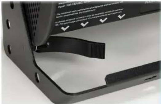
Figure 2 (SF-II 12 - Quick lever tilt adjustment)
Note: Secure the fixture with a safety bond. Fixing holes are provided in the endplates and fixture brackets.
2.4. Optics
The Studio Force II ^TM fixtures are built with lenses that optimize the beam spread. The unit comes with preinstalled symmetric lenses for high intensity homogenized output and extremely uniform wash. The beam distribution is symmetrical when Studio Force II ^TM is used to directly illuminate an area on stage. The fixture throws intense uniform white output at extreme intensity and provides a tight beam angle of ≈22^ .

natural_image
Six circular white objects arranged in a row, resembling decorative or abstract forms, with no visible text or symbols.Figure 3 (Symmetrical Lens)
Cyc & Border Lens
"Cyc Lens" and "Border Lens" are slide-in optical accessories available to adjust the light output of the Studio Force II™ fixtures, to suit a wide range of applications. One accessory slot is provided on the front of the fixture to hold a slide-in lens accessory. Matching indentations on both ends of lens are provided for locking the lens in place.
Studio Force II comes standard with a 22^× 22^ beam angle optics. 2 additional lenses can be position in front
the standard optics. The output beam angle with Border Lens is 43^ × 43^ and with CYC Lens, 80^ × 35^ . This can be seen in Figure 4 <

Figure 4 (Beam Angle)
Spring Plungers are pre-installed at the far ends of the accessory slot to lock in-place the slide-in panels. The height of the spring plungers is pre-set at the factory and requires no further adjustment.

Figure 5 (Optional slide-in lenses)
2.5. Control
Studio Force II™ fixture can operate as a stand-alone unit or can be controlled remotely via ANSI E1.11 USITT DMX 512-A protocol. The control function settings can be accessed through the touchscreen LCD display at the rear of the fixture.
Power-up Screen:

Figure 6 (Start-up Screen)
2.6. Main Menu
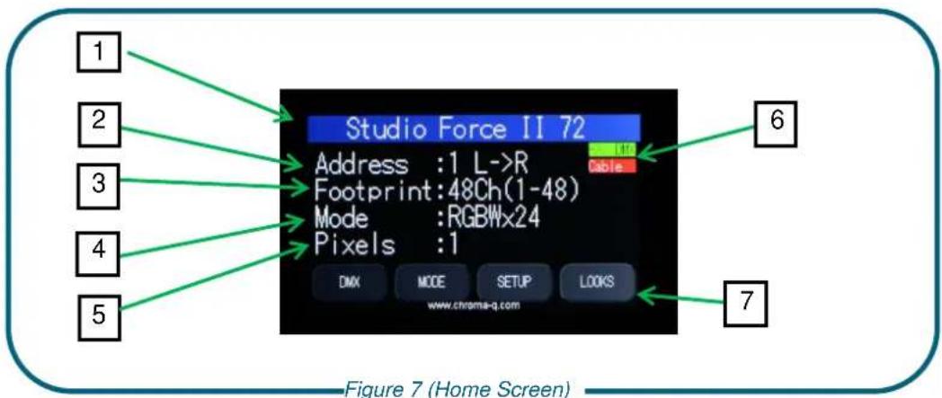
Once the unit is powered up, the touch screen LCD display shows the Main Menu with:
- The model name
- Address: The DMX starting address and orientation
- Footprint: number of DMX slots used in the current configuration
- Mode: current assigned control mode
- Pixels: Current dedicated pixels (or grouping) as per selected grouping & control mode
- Data Signal/Source Indicator: Current input status (DMX cable/DMX wireless/No data cable/No data Wireless)
- Configuration option buttons: Operational and control changes can be made by selecting any of the four configuration option buttons shown in the picture above to access DMX (address), Mode, Setup and preset Looks operation.
L→R shows LED pixels will be controlled beginning at left, going towards right. This can be reversed by choosing R→L in the Mode Menu options.
Note: The "Left" side of the fixture is at power/dmx IN; the "Right" side is at power/dmx out.
The LCD is backlit when the main menu is accessed and will turn off when left undisturbed for 5 seconds.
| Data Signal Indicator- Shows the presence and status of DMX signal | |
| No Data | - appears when the fixture is set at a DMX controllable mode and is not connected to an external DMX source/ console. |
| >> >DMX | - appears when the fixture is set at a DMX controllable mode and is receiving a DMX signal from an external DMX source/ console. |
| DMX >> | -appears when the fixture is set at Master and is outputting a DMX data signal. |
Table 4 (Data Signal Indicator)
Configuration option buttons
DMX
The factory default address is 1. The LCD screen displays the current DMX start address and the new DMX start address. In this screen, the numeric command buttons can be tapped, to set the new DMX start address.

| Command Button | Description |
| 0 – 9 | Tap in combination, to enter the new DMX start address |
| Apply | Tap to save the new DMX address. |
| Escape | Tap to Exit the screen. |
Table 5 (DMX Change Command Buttons)
To set/change the DMX start address,
- Main menu, tap on DMX
- Next screen will be, "Change DMX Address"
- Tap on 0-9 command buttons in combination, to enter the new DMX start address
- Tap on Apply to save
- Control goes back to the Main menu screen and the new DMX start address will be displayed
- Tap on Escape anytime to cancel
3. Mode
www.chroma-q.com
3.1. Mode Select Options
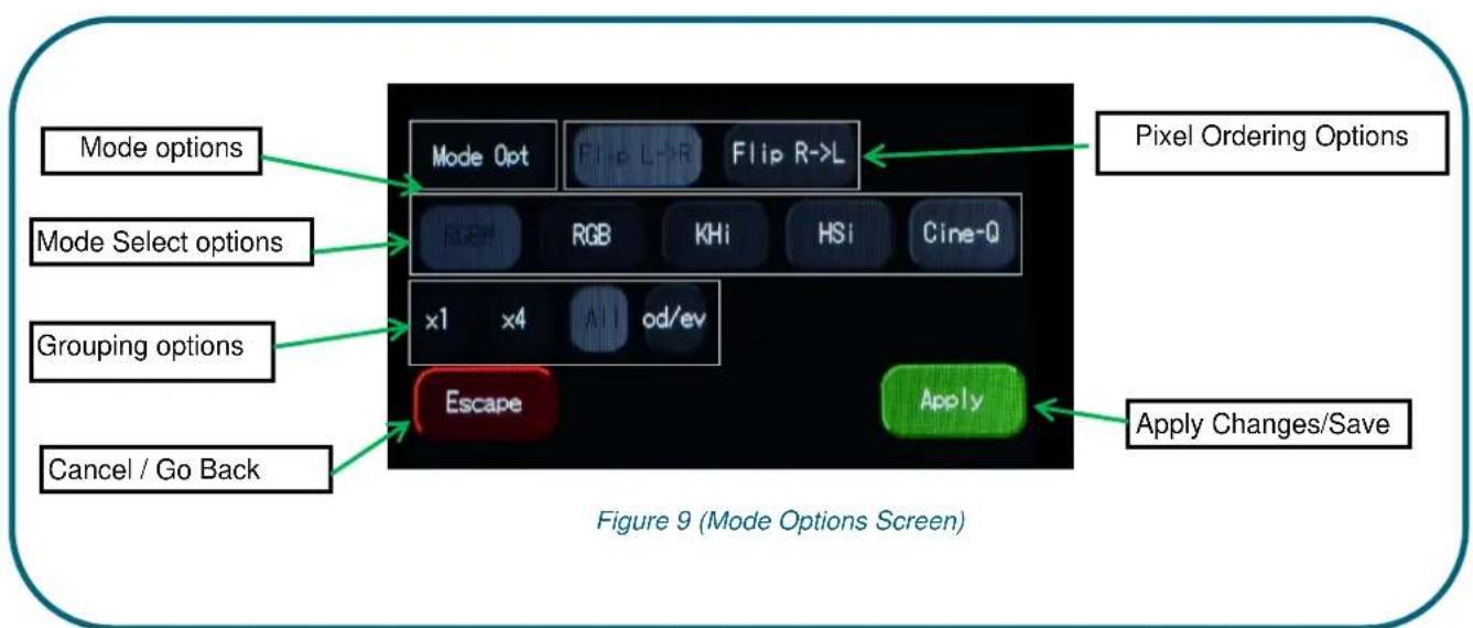
KHi (Kelvin, Hue, and intensity) gives 3 parameter channels to each group; 1 channel for colour temperature and 1 for hue (±Green), and third for the intensity. Hue channel when set at 50%, the colour output is at black body curve. Above 50%, it shifts towards green and below 50% it shifts towards red area on the black body curve. A separate definable intensity channel is particularly useful when creating intensity chases or when the grand master is used. Below table shows the CCT output, at different K, H, i settings. The DMX map is shown in Table 19 (DMX Map-KHi).
| K | H | i | CCT |
| 0% | 50% | 100% | ≈2800K |
| 12% | 50% | 100% | ≈3200K |
| 50% | 50% | 100% | ≈4400K |
| 75% | 50% | 100% | ≈5600K |
| 100% | 50% | 100% | ≈6500K |
Table 6 (KHi-CCT Output)
Cine-Q (Intensity Kelvin, Hue, Red, Green, Blue, White and Crossfade) is a combination of the KHI and RGBW mode, with the ability to crossfade between either mode. It gives 8 or 9 parameter channels to each group; one global intensity, one parameter for colour temperature and one for hue (±Green), and then Red, Green, Blue and White parameters. A crossfade parameter allows to fade from KH to RGBW parameters. The default value for Kelvin and Hue parameters should be 50%. The crossfade parameter can be set to 16-bit for a more accurate crossfade when using very long transition. The DMX map is shown in Table 20 (DMX Map-CINE-Q-iKHRGBW).

flowchart
graph TD
    A["INTENENSITY"] --> B["K&H"]
    B --> C["RGBW"]
    C --> D["CROSSFADE"]
    B --> E["SINGLE CELL"]
    C --> E
    E --> F["6 5 0 0 TO 2 8 0 0 k"]
    E --> G["GRE EN S H I F T"]
    E --> H["RED GREEN B L U E"]
    E --> I["WHITE"]
    style A fill:#f9f,stroke:#333
    style B fill:#ccf,stroke:#333
    style C fill:#cfc,stroke:#333
    style D fill:#fcc,stroke:#333
    style E fill:#cff,stroke:#333
    style F fill:#ffc,stroke:#333
    style G fill:#ffc,stroke:#333
    style H fill:#cfc,stroke:#333
    style I fill:#cfc,stroke:#333
Figure 10 (CINE-Q CROSSFADE)
RGBW (Red, Green, Blue and White): This mode assigns 4 DMX channels to set Red, Green, Blue and White levels in each cell, or group of cells. It provides 4 parameter channels that directly affect the intensity of each color within a group. Color is mixed by adjusting the levels of each of the four channels using an external DMX controller/ console. The DMX footprint will be determined by the selected grouping option. White (of about 3,500K) is achieved with only white channel at full. Refer to the Table 7 (SFII 72 DMX Grouping), Table 8 (SFII 48 DMX Grouping), Table 9 (SFII 12 DMX Grouping), for detail on grouping selection and DMX footprints. The DMX map is shown in Table 16 (DMX Map-RGBW).
To set the fixture to RGBW mode,
- On the Main Menu, tap Mode
- On the Mode screen, tap RGBW
- Tap Apply to save or Escape to cancel
RGB (Red, Green, and Blue) gives 3 parameter channels directly affecting the intensity of the corresponding group. Color is mixed by adjusting the levels of the three primary colors in each group. The DMX footprint will be determined by grouping option selected. The white color is automatically mixed in when all three colour parameters are engaged. The DMX map is shown in Table 17 (DMX Map-RGB).
To set the RGB mode,
- On the Main Menu, tap Mode
- On the Mode screen, tap RGB
- Tap Apply to save or Escape to cancel
HSi (Hue, Saturation and Intensity) gives 3 control channels to each group; 2 channels for hue and saturation and one intensity channel. A separate definable intensity channel is particularly useful when creating intensity chases or when the grand master is used. The hue channel has 255 different colors available and the saturation channel specifies the saturation level of that color. The saturation channel is fully saturated at full. White is achieved with the intensity channel to full and the saturation channel at zero. With this mode enabled, the Hue channel is from Red to Red (R→G→B→R). The DMX map is shown in Table 18 (DMX Map-HSi).
**Extended Control Channel: An extra Control parameter can be enabled, it will be place as the last parameter of the fixture control mode. The Control channel allows for remotely control certain aspect of the fixture such as the fan speed, PWM frequency and more functions.
3.2. Mode Options
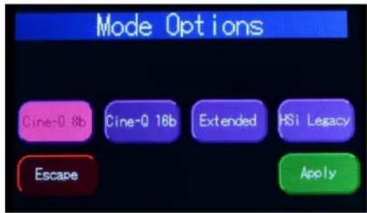
Cine-Q 16b The crossfade parameter can be set to 16-bit for a more accurate crossfade and better granularity, when using very long transition. When set at this mode, one extra channel (#9) is assigned for very small step increase/decrease in the intensity (0.0% to 1.0%) with change in the DMX fader value form 0-255. See Table 21 (DMX Map-CINE-Q-iKHRGBW-16bit) for the DMX Map.
| Mode | i | K | H | R | G | B | W | X | x |
| Cine-Q 8b | 1 | 2 | 3 | 4 | 5 | 6 | 7 | 8 | -- |
| Cine-Q 16b | 1 | 2 | 3 | 4 | 5 | 6 | 7 | 8 | 9 |
**Extended This setting assigns one extra channel in the end, which allows remote override of certain settings such as engine frequency, fan speed, Dimmer curve and DMX Lost state. This option allows users to temporarily override touch screen menu entered settings, using one extra channel on a DMX console. To override a current setting in the fixture,
- Set the value of this channel to the desired setting (DMX Value) listed in the Table 23 (DMX Map-Extended Control Channel).
- Wait for 5 sec.
- The fixture will retain that setting, until it is changed again or the fixture is power cycled.
- To avoid any unintentional settings override, set the extended channel back to DMX value 0.
After the power cycle, the extended control setting will be reset and the fixture will default back to the last settings set by the touch screen display menu or the RDM.
HSi Legacy The option allows the new Studio force fixtures match the HSi pattern, with old Chroma-Q HSi mode enabled fixtures. With Legacy hue mode enabled, the Hue channel is from Blue to Blue (B→G→R→B).
3.3. Grouping Options
Studio Force II ^TM offers a powerful, wide variety of grouping options for the individual cells (or pixels) within each fixture. Grouping is independent of control mode selection. A Studio Force II ^TM 72 fixture consists of 24 cells, a Studio Force II ^TM 48 fixture consists of 16 cells and a Studio Force II12 ^TM fixture consists of 4 cells. "Cell" or pixel grouping allows individual control of each single cell or various grouping of cells as defined in the tables below. In "ALL" grouping, all cells in the Studio Force II ^TM 72/48/12, the fixtures will be controlled as 1 group. In x1 each cell is being controlled independently for a total of 24, 16 or 4 individual cells for the Studio Force II ^TM 72, 48 or 12 respectively. The number in the table below, indicate the group number.
Od / Ev: Controls every other cell (pixels) in two groups of control – odd cell and even cells.
X4: (48 and 72 models only) Controls cells in group of 4
X1: Each cells are controlled individually
Grouping & DMX Addressing
| Grouping: Studio Force II ^TM 72 | Flip: L→R | |||||||||||||||||||||||
| Group Selected | Group Number(s) | |||||||||||||||||||||||
| All | 1 | 1 | 1 | 1 | 1 | 1 | 1 | 1 | 1 | 1 | 1 | 1 | 1 | 1 | 1 | 1 | 1 | 1 | 1 | 1 | 1 | 1 | 1 | 1 |
| x4 | 1 | 1 | 1 | 1 | 2 | 2 | 2 | 2 | 3 | 3 | 3 | 3 | 4 | 4 | 4 | 4 | 5 | 5 | 5 | 5 | 6 | 6 | 6 | 6 |
| x1 | 1 | 2 | 3 | 4 | 5 | 6 | 7 | 8 | 9 | 10 | 11 | 12 | 13 | 14 | 15 | 16 | 17 | 18 | 19 | 20 | 21 | 22 | 23 | 24 |
| Od/Ev | 1 | 2 | 1 | 2 | 1 | 2 | 1 | 2 | 1 | 2 | 1 | 2 | 1 | 2 | 1 | 2 | 1 | 2 | 1 | 2 | 1 | 2 | 1 | 2 |
Table 7 (SFII 72 DMX Grouping)
| Grouping: Studio Force II^TM 48 | Flip: L→R | |||||||||||||||
| Group Selected | Group Number(s) | |||||||||||||||
| All | 1 | 1 | 1 | 1 | 1 | 1 | 1 | 1 | 1 | 1 | 1 | 1 | 1 | 1 | 1 | 1 |
| x4 | 1 | 1 | 1 | 1 | 2 | 2 | 2 | 2 | 3 | 3 | 3 | 3 | 4 | 4 | 4 | 4 |
| x1 | 1 | 2 | 3 | 4 | 5 | 6 | 7 | 8 | 9 | 10 | 11 | 12 | 13 | 14 | 15 | 16 |
| Od/Ev | 1 | 2 | 1 | 2 | 1 | 2 | 1 | 2 | 1 | 2 | 1 | 2 | 1 | 2 | 1 | 2 |
Table 8 (SFII 48 DMX Grouping)
| Studio Force II^TM 12 | L→R | |||
| Group Selected | Group Number(s) | |||
| All | 1 | 1 | 1 | 1 |
| x1 | 1 | 2 | 3 | 4 |
| Od/Ev | 1 | 2 | 1 | 2 |
Table 9 (SFII 12 DMX Grouping)
3.4. Pixel ordering Options
The starting DMX address can be selected to be on the right or left of the fixture as indicated on the display. The "Left" side of the fixture is at power/dmx IN; the "Right" side is at power/dmx out. Table #10, is an example of address ordering for a Studio Force II™ 72, with x1 Grouping selected.
| L→R | 1 | 2 | 3 | 4 | 5 | 6 | 7 | 8 | 9 | 10 | 11 | 12 | 13 | 14 | 15 | 16 | 17 | 18 | 19 | 20 | 21 | 22 | 23 | 24 |
| R→L | 24 | 23 | 22 | 21 | 20 | 19 | 18 | 17 | 16 | 15 | 14 | 13 | 12 | 11 | 10 | 9 | 8 | 7 | 6 | 5 | 4 | 3 | 2 | 1 |
Table 10 (Flip Grouping)
3.5. DMX Footprints
Number of DMX Channels used in Mode/Grouping Combinations P.S.: Add one extra channel when Extended mode is enabled
| Studio Force II^TM 72 | ||||||
| Control Mode | KHi | Cine-Q | Cine-Q16bit | RGBW | RGB | HSi |
| Grouping | ||||||
| All | 3 | 8 | 9 | 4 | 3 | 3 |
| x4 | 18 | 48 | 54 | 24 | 18 | 18 |
| x1 | 72 | 192 | 216 | 96 | 72 | 72 |
| Od/Ev | 6 | 16 | 18 | 8 | 6 | 6 |
Table 11 (SFII 72 Mode-Grouping DMX Values)
| Studio Force II^TM 48 | ||||||
| Control Mode | KHi | Cine-Q | Cine-Q16bit | RGBW | RGB | HSi |
| Grouping | ||||||
| All | 3 | 8 | 9 | 4 | 3 | 3 |
| x4 | 12 | 32 | 36 | 16 | 12 | 12 |
| x1 | 48 | 128 | 144 | 64 | 48 | 48 |
| Od/Ev | 6 | 16 | 18 | 8 | 6 | 6 |
Table 12 (SFII 48 Mode-Grouping DMX Values)
| Studio Force IITM 12 | ||||||
| Control Mode | KHi | Cine-Q | Cine-Q 16bit | RGBW | RGB | HSi |
| Grouping | ||||||
| All | 3 | 8 | 9 | 4 | 3 | 3 |
| x1 | 12 | 32 | 36 | 16 | 12 | 12 |
| Od/Ev | 6 | 16 | 18 | 8 | 6 | 6 |
Table 13 (SFII 12 Mode-Grouping DMX Values)
4. Set up Menu
Studio Force II ^TM technical operation can be changed and viewed using the Setup menu options.
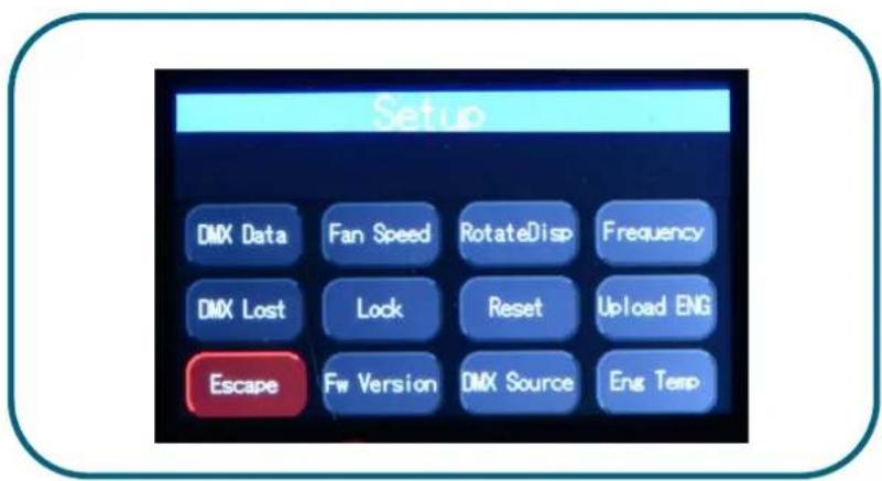
Figure 11 (Setup Menu Screen)
| Command | Description |
| DMX Data | Displays the incoming DMX levels for the assigned channels. |
| Fan Speed | 4 Fan Speed options are accessed through the Fan Speed screen:Quiet – internal fan is off and maximum intensity reduced to 80%.Studio – internal fan is at low speed.Live – internal fan is on.Live-Quiet – internal fan is automatically switched ON when light output is ON and vice-versa. |
| Rotate Disp | This button rotates the orientation of the Touch Screen Display 180 degrees |
| Frequency | Frequency options can be viewed and selected. Available options:750 Hz, 1500 Hz, 3000Hz, 6000 Hz, 12000Hz, 24000Hz. |
| DMX Lost | The fixture can be set with 3 options when DMX data is lost:Last data – holds the last valid DMX stateNo Output – the fixture switches to offLook – select a prerecorded Look to execute |
| Lock | The touch screen LCD can be set to lock or unlock in the Lock feature screen. |
| Reset | Reset Settings options are accessed through the Reset Setting screen:Default – Factory default settingsUser – User defined settings |
| Upload ENG | The fixture can be set for light engine software upload/ upgrade through this screen. |
| FW Version | Displays current software version. |
| DMX Source | Displays current DMX source – cable or wireless |
| Eng Temp | Displays LIVE value for temperature of all the engines in fixture. |
| Escape | Exit the screen |
Table 14 (Setup Menu Options)
4.1. DMX Data
This option allows user to see the DMX channel intensity levels, being received by the fixture. This DMX channel entered will be formatted and displayed on this screen, based on selected mode and grouping. The values read from 0 to 99 (as 0%-100% intensity).

Figure 12 (DMX Data Screen)
To show DMX Data,
- On the Main Menu, tap SETUP
- Then tap DMX Data
- The display shows the DMX start channel and the values (0-99) of the DMX channels
- Tap Escape to go to back
4.2. Fan Speed
The internal fan of the fixture can be set to four speed options to regulate noise levels and the cooling process.

Figure 13 (Fan Mode Select Screen)
| Quiet | The internal fans are off and light output is reduced by 20%. |
| Studio | The fan speed is at low velocity and light output is at 100%. |
| Live | The fan speed is at high velocity and the light output at 100% |
| Live-Quiet | Internal fans are turned off when all DMX values are at 0%. |
Note: Studio Force II ^TM unit is internally temperature protected at all times.
To set the Fan Speed Mode,
- On the Main Menu, tap Setup
- Then tap Fan Speed option
- On the Fan Speed screen, select a Fan Speed option, and then tap Apply to save
4.3. Rotate Display
Display screen menu can be rotated 180^ (upside down) by tapping on this button.
To set the orientation of the display,
- On the Main Menu screen, tap Setup Menu.
- On the Screen Setup screen, tap RotateDisp
- The display screen rotates by 180 degrees
4.4. PWM Frequency
The Studio Force II has following frequency settings available: 750 Hz, 1500 Hz, 3000 Hz, 6000 Hz, 12000 Hz, 24000 Hz. This allows for the LED scan rate to be synchronized with the video camera and avoid a flickering effect.
Trade-off: Better dimming is achieved at lower frequencies; flickering effect is minimized at higher PWM frequencies.

Figure 14 (PWM Select Screen)
To set the Frequency,
- On the Main Menu, tap Setup Menu
- On the Setup screen, tap Frequency
- On the Frequency screen, select and tap a Frequency option, then tap Apply to save
4.5. DMX Lost
If DMX is not detected various output options can be selected in this mode:

Figure 15 (DMX Lost Mode Select Screen)
| OFF | will snap to off after 5 seconds |
| Hold | will hold the last valid DMX state |
| Look 1-31 | will snap to the user saved look |
To set DMX Lost action;
- On the Main Menu, tap Setup Menu
- On the Setup screen, tap DMX Lost
- On the When DMX Lost screen, select and tap an output option, then tap Apply to save
Note: If a Look is selected for playback when DMX is lost, the unit will playback the selected look on power up, as long as DMX is not present.
4.6. Lock feature
Factory default sets the display screen to turn off and lock when untapped for 30 seconds. A lock symbol appears on the screen, when tapped. This feature provides protection against accidental user input.
To disable or enable the lock,
- On the Main Menu, tap Setup Menu
- On the Setup screen, tap Lock button.
- On the Lock Feature screen, tap Enable or Disable, then tap Apply to save

Figure 16 (Lock Feature Select Screen)
If the Lock feature is enabled, touch and hold the lock icon for 5 seconds to unlock.

Figure 17 (Lock Feature Select Icon)
4.7. Reset and Factory Defaults
In this menu,
- Current user settings can be saved.
- The fixture can be reset to the save user settings.
- The fixture can be reset to the factory default settings. All recorded Looks are erased.

Figure 18(Reset Settings Screen)
To save the current user settings,
- Review all settings
- On the Main Menu, tap Setup Menu
- On the Setup screen, tap Reset
- On the Reset Setting screen, press and hold
"Save User" for 5 seconds to save the current settings.
(Follow the text prompt that appears on the screen)
To reset the fixture to the save user settings,
- On the Main Menu, tap Setup Menu
- On the Setup screen, tap Reset
- On the Reset Setting screen, tap User
- Press and hold Apply for 3 seconds to restore the saved user settings
To reset the fixture to the factory default settings,
- On the Main Menu, tap Setup Menu
- On the Setup screen, tap Reset
- On the Reset Setting screen, tap Default
- Press and hold Apply for 3 seconds to restore the factory default settings
| DMX Address | 1 |
| Foot Print | 3ch (1-3) |
| Mode | KHI |
| Lock | Disabled |
| Pixels | All |
| DMX Lost | Last data (HOLD) |
| Fan Speed | Live |
| Frequency | 750Hz |
| Reset | Default |
| Flip | L→R |
| Cine-Q 8b | Enabled |
Table 15 (Factory Default Settings)
4.8. Upload Engine
RECOMMENDED ONLY FOR FACTORY TRAINED PERSONNEL.
LED Engine software can be uploaded to the fixture from the Chroma-Q Uploader II by accessing this menu.
Refer to the Quick Start Guide of the Chroma-Q Uploader II.
Link: http://www.chroma-q.com/support/quick-start/CHUSBLOADERII_Uploader-quickstartguide.pdf
Software for the LED engines must be uploaded to the Studio Force II ^TM using the Chroma-Q Uploader II:
- In "Setup", select "Upload Engines" then press Enter, and the display shows "Ready"
- Connect an XLR 5-pin cable from the Uploader to the individual Studio force II unit
- Power-up the Uploader - display shows the file name, and "Ready"
- Press the "ERASE TARGET" button once to clear the target firmware
- Press the "Start Uploading" button once to execute the uploading
- An animated progress is displayed on the Uploader and CF unit indicating the upload process
- "UPLOADING DONE" appears on the Uploader upon completion of a successful upload and the target device resets to the Main Menu
- Power-cycle the unit
Note: The Chroma-Q Uploader II must be purchased separately.
4.9. FW Version
This screen displays current software version of fixture at the address header. For added versatility, Individual firmware versions of all the engines are also displayed.
4.10. DMX Source
This enables the input connection.

Figure 19 (DMX Source Select Screen)
| INPUT | DMX from console via cable |
| WIRELESS | Lumen Radio input |
Select the DMX source and press Apply.
4.11. Engine Temp
Tap on this to see individual temperature in ^9 Celsius of each engine in the fixture. Each LED engine drives two cells on the Studio Force II ^TM .
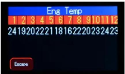
Figure 20 (Light Engine Temp Screen)
5. Look Store
Looks can be recorded to the internal flash memory by users and will be preserved on power down. However, looks will be returned to default setting if Default Reset is performed.

Figure 21 (Look Selection Screen)
- Set the Studio Force II ^TM to the desired color and intensity using a DMX console.
- Go to the Look Store screen as shown above and select the Look number where the Look will be stored.
- Press Store for 2 seconds to save the Look.
- "Look Stored" will be displayed on the screen to confirm.
- Multiple looks can be saved from Look (1-31).
- Playback button allows the user to check what look is at (1-31).
6. Thermal Performance
The Studio Force II™ 12, 48 & 72 feature in-built fans that control the internal temperature of the fixture. If the internal temperature of the Studio Force exceeds 75^ the output of the fixture will be reduced as an automatic protection feature. This may happen when the ambient temperature is over 40^ or the internal fans are blocked or damaged due to mishandling of the fixture. The airflow to and from the fan must not be constricted to maintain the maximum light output of the Studio Force II™.
7. Troubleshooting
Troubleshooting is a process of elimination. First, rule out the other field factors (i.e. bad connections, faulty cables and power supplies). For technical support and/or parts, please contact nearest Chroma-Q dealer.
| Symptom | Possible Cause | Solution |
| Fixture does not respond to DMX control. | 1. Set to wrong or different DMX address.2. Bad cable connecting DMX control and fixture. Bad in/through connection between adjacent fixtures.3. Console patch is incorrect. | 1. Check DMX address and Mode settings.2. Check/replace DMX run from the console.3. Check DMX values in the Setup/DMX Data screen as described above to verify the fixture is “seeing” the DMX data. |
| Noise from fixture unit. | Fan malfunction. | Check fan. |
| Low LED output. | Internal temperature is over the limit. Fan is not working. | ·Verify Engine temperature using the Setup/ Eng Temp screen.·Check “Fan Control” mode. Check fan.·Check for airflow - to and from the internal fan.·Check area ventilation. |
8. Maintenance
With care, the Studio Force ^™ II will require little or no maintenance. However, as the unit is likely to be used in a stage environment, we recommend periodical inspection and cleaning of any resulting dust on the unit.
Do not spray liquids on the front or rear panel. Do not use solvents to clean the fixture. If the front enclosure requires cleaning, wipe with a mild detergent on a damp cloth.
9. Specification
9.1. Technical specifications
| Studio Force II V72 | Studio Force II V48 | Studio Force II V12 | |
| Product | CHSF2V72 | CHSF2V48 | CHSF2V12 |
| Dimensions: | 1759mm x182mm x177mm 69.25" x7.25" x 7" | 1,181mm x 165mm x191mm / 46.5" x 6.5"x 7.5" | 335mm x 190mmx 218mm / 13.2" x7.5" x 8.6" |
| Weight: | 24kg / 53lbs | 18 Kg / 40lbs | 5 Kg / 11lbs |
| Power input | 100-240VAC, 800VA, 50-60Hz | 100-240VAC, 550VA, 50-60Hz | 100-240VAC, 160VA, 50-60Hz |
| Power | Neutrik powerConTRUE1 | ||
| Data | Neutrik XLR 5-pin | ||
| Control | ANSI E1.11 USITT DMX 512-A | ||
| Cooling | Forced - 2 fans | Forced - 2 fans | Forced - 1 fan |
| Construction: | Anodized aluminum extrusion | ||
| Color: | RAL 9005/ Black, RAL 9016/ White | ||
| LED Pixels: | 24 | 16 | 4 |
| Optics: | Specialized close focus lens | ||
| Beam angle: | ~ 22° (approx.) | ||
| Beam | Symmetrical direct illumination | ||
| CCT: | Adjustable 1000 – 10000K (fully calibrated between 2800K and 6500K) | ||
| CRI: | Up to 94 | ||
| Lamp Life: | Up to 50,000 hours | ||
| IP Rating: | IP20 | ||
| Operating | 0°C to 40°C | ||
| Approvals: | CISPR 22:2006/EN55022:2006 & CISPR 24:1997/EN55024:1998 ICES-003:2004 & FCC Part 15 Subpart B:2007CSA C22. No. 166-M1983:R2008UL 1573:2003; UL 8750 | ||
CE
9.2. Technical Drawings
Studio Force II 72
![[1743.1] 68.63](/content/2026/05/980299/images/7c2c2cfea27049b05c6d8be0aa72d8fb069f27d12d6d232abb275e4129fc2f62.jpg)
![[1769] 69.64](/content/2026/05/980299/images/368e101178f768997ec3962252e0c9c0fbc995a51b5c250cc46be4d64783def7.jpg)
![[1673.7] 65.89 [93.2] 3.67](/content/2026/05/980299/images/96b2ac32be7c08b27450df01e77ef6911393e946506a1a7309026ae82d3e2735.jpg)
![[3.2] .13 [92.1] 3.63 [147.8] 5.82 [189.1] 7.45 [139.7] 5.50 [165.1] 6.50](/content/2026/05/980299/images/e725373828814a6d7727b0b671eb0c020aa76ca1ae74e21eb00cbb088d0b4ae8.jpg)
www.chroma-q.com
Studio Force II 48

other
| Dimension | Value | | --------- | ------- | | Total Length | 1165.2 | | Total Height | 45.88 |![[1184.8] 46.64](/content/2026/05/980299/images/81bcdd19da7810771b58ffddd1f48dad1b9e1b93dde79b2c39e312441bd9266f.jpg)
![[93.2] 3.67 [1089.5] 42.89](/content/2026/05/980299/images/f0d0d067eaea0ba8cbb4361ba8e973c0904f1a6fc149a2657a55dc0bc0190743.jpg)
![[3.2] .13 [92.1] 3.63 [147.8] 5.82 [185.8] 7.32 [139.7] 5.50 [165.1] 6.50](/content/2026/05/980299/images/5157478c2012d0d98511faeee4982b0f4a1251c65ad9782092729796983a9c1b.jpg)
Studio Force II 12
![© Chroma-Q® Studio Force II V12 [334.5] 13.17](/content/2026/05/980299/images/fd21f8528fffc23a98015fa4c235c185eca479836c564efb92181a64fec3f1f8.jpg)
![[168.2] 6.62 [133.4] 5.25 [3] .12 [168.7] 6.64 [208.4] 8.20 [191.2] 7.53](/content/2026/05/980299/images/78ea9ad0b67ccd8459fafada8e775509ec01f2cd98894b56cbc71abb670f6658.jpg)
![[111.1] 4.375 [319.1] 12.56](/content/2026/05/980299/images/1b0b652dd268cafec70957b28696846d606e353769ea49cc61b8da5b021895de.jpg)
- Menu Tree

flowchart
graph TD
    A["Main Menu"] --> B["DMX"]
    A --> C["MODE"]
    A --> D["SETUP"]
    A --> E["LOOKS"]

    B --> F["Address"]
    B --> G["Group"]
    G --> H["x1"]
    G --> I["x4"]
    G --> J["od/ev"]
    G --> K["All"]
    G --> L["RGBW"]
    G --> M["RGB"]
    G --> N["KHi"]
    G --> O["HSi"]
    G --> P["Cine-Q"]
    G --> Q["Cine-Q 8/16 bit"]
    G --> R["Extended On/Off"]
    G --> S["HSi Legacy on/off"]

    C --> T["Mode"]
    T --> U["Mode Opt"]
    U --> V["Flip R>L"]
    U --> W["Flip L>R"]
    C --> X["DMX Data"]
    C --> Y["Fan Speed"]
    X --> Z["Quiet"]
    X --> AA["Studio"]
    X --> AB["Live"]
    X --> AC["Live-Quiet"]

    C --> AD["Frequency"]
    AD --> AE["750 Hz"]
    AD --> AF["1,500 Hz"]
    AD --> AG["3,000 Hz"]
    AD --> AH["6,000 Hz"]
    AD --> AI["12,000 Hz"]
    AD --> AJ["24,000 Hz"]

    D --> AK["DMX Lost"]
    AK --> AL["Hold"]
    AK --> AM["OFF"]
    AK --> AN["Look (Select)"]

    D --> AO["Lock"]
    AO --> AP["Disable"]
    AO --> AQ["Enable"]

    D --> AR["Reset"]
    AR --> AS["Default"]
    AR --> AT["User"]
    AR --> AU["KHL"]

    D --> AV["Upload Eng"]
    AV --> AW["Cable"]

    D --> AX["Fw Version"]
    AX --> AY["Wireless"]

    D --> AZ["DMX Source"]
    AZ --> BA["Cable"]

    D --> BB["Eng Temp"]

    D --> BC["Select"]
    BC --> BD["Playback"]

    D --> BE["Store"]
www.chroma-q.com
11. DMX Map
11.1. Studio Force II DMX map for RGBW Control Mode:
Table 16 (DMX Map-RGBW)
| RGBW | Value | Function | Fade Status | Default Value |
| 1 | Red | |||
| 0 - 255 | Minimum → Maximum Intensity | Fade | 0 | |
| 2 | Green | |||
| 0 - 255 | Minimum → Maximum Intensity | Fade | 0 | |
| 3 | Blue | |||
| 0 - 255 | Minimum → Maximum Intensity | Fade | 0 | |
| 4 | White | |||
| 0 - 255 | Minimum → Maximum Intensity | Fade | 0 | |
| 5** | Extended Controls | |||
| 0 - 255 | See Control channel table for details | Snap | 0 |
**
Channel 1 through 4 will repeat for each cell control according to the selected grouping mode
Control parameter is only present when Extended mode is enabled
Control parameter is always last, its position will change according the grouping mode.
For example, in odd/even grouping mode, the control parameter would be on 9
11.2. Studio Force II DMX map for RGB Control Mode:
Table 17 (DMX Map-RGB)
| RGB | Value | Function | Fade Status | Default Value |
| 1 | Red | |||
| 0 - 255 | Minimum → Maximum Intensity | Fade | 0 | |
| 2 | Green | |||
| 0 - 255 | Minimum → Maximum Intensity | Fade | 0 | |
| 3 | Blue | |||
| 0 - 255 | Minimum → Maximum Intensity | Fade | 0 | |
| 4** | Extended Controls | |||
| 0 - 255 | See Control channel table for details | Snap | 0 |
Note: Channel 1 through 3 will repeat for each cell control according to the selected grouping mode
**
Control parameter is only present when Extended mode is enabled
Control parameter is always last, its position will change according the grouping mode.
For example, in odd/even grouping mode, the control parameter would be on 7
11.3. Studio Force II DMX map for HSi Control Mode:
Table 18 (DMX Map-HSi)
| HSi | Value | Function | Fade Status | Default Value |
| 1 | Hue* | |||
| 0 - 255 | Color Spectrum 0 → 360 Red → Red | Fade | 0 | |
| 2 | Saturation | |||
| 0 - 255 | Desaturated → Saturated | Fade | 0 | |
| 3 | Intensity | |||
| 0 - 255 | Minimum → Maximum Intensity | Fade | 0 | |
| 4** | Extended Controls | |||
| 0 - 255 | See Control channel table for details | Snap | 0 |
Note: Channel 1 through 3 will repeat for each cell control according to the selected grouping mode
* With Legacy hue mode enabled, the Hue channel is from Blue to Blue
** Control parameter is only present when Extended mode is enabled
Control parameter is always last, its position will change according the grouping mode.
For example, in odd/even grouping mode, the control parameter would be on 7
11.4. Studio Force II DMX map for KHi Control Mode:
Table 19 (DMX Map-KHi)
| KHi | Value | Function | Fade Status | Default Value |
| 1 | Kelvin | |||
| 0 - 255 | Warm → Cold | Fade | 128 | |
| 0 | 2800K | |||
| 64 | 3200K | |||
| 128 | 4400K | |||
| 192 | 5600K | |||
| 255 | 6500K | |||
| 2 | Hue | |||
| 0 - 255 | Minus Green → Plus Green | Fade | 128 | |
| 3 | Intensity | |||
| 0 - 255 | Minimum → Maximum Intensity | Fade | 0 | |
| 4** | Extended Controls | |||
| 0 - 255 | * See Control channel table for details | Snap | 0 |
Note: Channel 1 through 3 will repeat for each cell control according to the selected grouping mode
** Control parameter is only present when Extended mode is enabled
Control parameter is always last, its position will change according the grouping mode.
For example, in odd/even grouping mode, the control parameter would be on 7
11.5. Studio Force II DMX map for Cine-Q i-KH-RGBW Control Mode
Table 20 (DMX Map-CINE-Q-iKHRGBW)
| Cine-Q I-KH-RGBW | Value | Function | Fade Status | Default Value |
| 1 | Intensity | |||
| 0 - 255 | Minimum → Maximum Intensity | Fade | 0 | |
| 2 | Kelvin | |||
| 0 - 255 | Warm → Cold | Fade | 128 | |
| 0 | 2800K | |||
| 64 | 3200K | |||
| 128 | 4400K | |||
| 192 | 5600K | |||
| 255 | 6500K | |||
| 3 | Hue (Tint) | |||
| 0 - 255 | Minus Green → Plus Green | Fade | 128 | |
| 4 | Red | |||
| 0 - 255 | Minimum → Maximum Intensity | Fade | 0 | |
| 5 | Green | |||
| 0 - 255 | Minimum → Maximum Intensity | Fade | 0 | |
| 6 | Blue | |||
| 0 - 255 | Minimum → Maximum Intensity | Fade | 0 | |
| 7 | White | |||
| 0 - 255 | Minimum → Maximum Intensity | Fade | 0 | |
| 8 | Q-Fade | |||
| 0 - 255 | KH → RGBW | Fade | 0 | |
| 9** | Extended Controls | |||
| 0 - 255 | * See Control channel table for details | Snap | 0 |
Note: Channel 1 through 8 will repeat for each cell control according to the selected grouping mode
Control parameter is only present when Extended mode is enabled
Control parameter is always last, its position will change according the grouping mode.
For example, in odd/even grouping mode, the control parameter would be on 17
11.6. Studio Force II DMX map for Cine-Q i-KH-RGBW 16bit Control Mode
Table 21 (DMX Map-CINE-Q-iKHRGBW-16bit)
| Cine-Qi-KH-RGBW16bit | Value | Function | Fade Status | Default Value |
| 1 | Intensity | |||
| 0 - 255 | Minimum → Maximum Intensity | Fade | 0 | |
| 2 | Kelvin | |||
| 0 - 255064128192255 | Warm → Cold2800K3200K4400K5600K6500K | Fade | 128 | |
| 3 | Hue (Tint) | |||
| 0 - 255 | Minus Green → Plus Green | Fade | 128 | |
| 4 | Red | |||
| 0 - 255 | Minimum → Maximum Intensity | Fade | 0 | |
| 5 | Green | |||
| 0 - 255 | Minimum → Maximum Intensity | Fade | 0 | |
| 6 | Blue | |||
| 0 - 255 | Minimum → Maximum Intensity | Fade | 0 | |
| 7 | White | |||
| 0 - 255 | Minimum → Maximum Intensity | Fade | 0 | |
| 8 | 0 - 65535 | Q-Fade (msb) | Fade | 0 |
| KH → RGBW | ||||
| 9 | Q-Fade (lsb) | |||
| KH → RGBW | ||||
| 10** | Extended Controls | |||
| 0 - 255 | * See Control channel table for details | Snap | 0 |
Note: Channel 1 through 9 will repeat for each cell control according to the selected grouping mode
Control parameter is only present when Extended mode is enabled
Control parameter is always last, its position will change according the grouping mode.
For example, in odd/even grouping mode, the control parameter would be on 19
11.7. Studio Force II DMX map group modes
Table 22 (DMX Map-Grouping Modes)
| Grouping mode | Description | Number of individual cells control | ||
| Studio Force II 12 | Studio Force II 48 | Studio Force II 72 | ||
| All | Entire fixture as one | 1 | 1 | 1 |
| X4 | Group by 4 cells | 1 | 4 | 6 |
| Odd/Even | Fixture is alternating cells | 2 | 2 | 2 |
| Single | Individual cell control | 4 | 16 | 24 |
11.8. Studio Force II DMX map Control channel
Table 23 (DMX Map- Extended Control Channel)
| Function name | Default | From | To | Description |
| Control channel | ||||
| No Function | 0 | 2 | ||
| Reserved | 3 | 40 | Reserved for future feature | |
| Fan Speed Off (if possible) | 41 | 42 | Fan will never start, fixture output can be reduced or limited | |
| Fan Speed Low | 43 | 44 | Slow fan speed (fixture output can be reduced or limited) | |
| Fixed fan speed = full | 45 | 46 | Maximum speed on fan | |
| Fixed fan speed = full, regulated light output intensity | X | 47 | 48 | Maximum speed on fan but only when needed |
| Reserved | 49 | 70 | Reserved for future feature | |
| PWM 750 | 71 | 72 | Set PMW rate | |
| PWM 1500 | 73 | 74 | Set PMW rate | |
| PWM 3000 | 75 | 76 | Set PMW rate | |
| PWM 6000 | X | 77 | 78 | Set PMW rate |
| PWM 12000 | 79 | 80 | Set PMW rate | |
| PWM 24000 | 81 | 82 | Set PMW rate | |
| Reserved | 83 | 150 | Reserved for future feature | |
| DMX Lost default Fixture stay to the last state | X | 151 | 152 | |
| DMX Lost default Fixture goes black | 153 | 154 | ||
| Reserved | 155 | 156 | Reserved for future feature | |
| DMX Lost default fixture to selected look | 157 | 158 | ||
| Reserved | 159 | 248 | Reserved for future feature | |
| No Function | 249 | 255 |
Values must be held for 5 second before its function is activated
12. RDM FUNCTIONS
Studio Force II RDM Supported parameters are:
DEVICE_INFO
IDENTIFY_DEVICE
DMX_START_ADDRESS
SOFTWARE_VERSION_LABEL
DEVICE LABEL
SENSOR DEFINITION
PARAMETER DESCRIPTION
DMX_PERSONALITY
DMX PERSONALITY DESCRIPTION
DEVICE MODEL DESCRIPTION
MANUFACTURER_LABEL
DEVICE_LABEL
SENSOR DEFINITION
SENSOR VALUE
REST_DEVICE
12.1. FREQUENCY, FAN\_SPEED and GROUPING
RDM Values for Frequency are as follows
| Byte Value | Frequency |
| 0x01 | 750Hz |
| 0x02 | 1500Hz |
| 0x03 | 300Hz |
| 0x04 | 6000Hz |
| 0x05 | 12000Hz |
| 0x06 | 24000Hz |
RDM Values for Fan Speed Modes are as follows
| Byte Value | Fan Speed |
| 0x01 | Quiet |
| 0x02 | Studio |
| 0x03 | Live |
| 0x04 | Live-Quiet |
RDM Values for Grouping are as follows
| Byte Value | Grouping |
| 0x01 | X1 |
| 0x02 | X2 |
| 0x03 | X4 |
| 0x04 | Od/Ev |

- Warranty Statement
- Disclaimer
- Important Notice:
- WARNING!
- Read the safety precautions in this section before installing, powering, operating or servicing this product.
- PROTECTION FROM ELECTRIC SHOCK
- PROTECTION FROM BURNS AND FIRE
- PROTECTION FROM INJURY
- Contents
- Contents....5
- Cyc & Border Lens....9
- Product overview
- Operation
- Unpacking the units
- Cabling
- Maximum Number of fixtures connected in a series:
- Mounting
- Optics
- Cyc & Border Lens
- Control
- Main Menu
- Configuration option buttons
- DMX
- Mode
- Mode Select Options
- Mode Options
- Grouping Options
- Pixel ordering Options
- DMX Footprints
- Set up Menu
- DMX Data
- Fan Speed
- Rotate Display
- PWM Frequency
- DMX Lost
- Lock feature
- Reset and Factory Defaults
- Upload Engine
- RECOMMENDED ONLY FOR FACTORY TRAINED PERSONNEL.
- FW Version
- DMX Source
- Engine Temp
- Look Store
- Thermal Performance
- Troubleshooting
- Maintenance
- Specification
- Technical specifications
- Technical Drawings
- Studio Force II 72
- Studio Force II 12
- DMX Map
- Studio Force II DMX map for RGBW Control Mode:
- Studio Force II DMX map for RGB Control Mode:
- Studio Force II DMX map for HSi Control Mode:
- Studio Force II DMX map for KHi Control Mode:
- Studio Force II DMX map for Cine-Q i-KH-RGBW Control Mode
- Studio Force II DMX map for Cine-Q i-KH-RGBW 16bit Control Mode
- Studio Force II DMX map group modes
- Studio Force II DMX map Control channel
- RDM FUNCTIONS
- FREQUENCY, FAN\_SPEED and GROUPING
Brand : Chrome-Q
Model : Studio Force II 48
Category : Lighting