
ELVOX 46NVR.32 - Video recorder Vimar - Free user manual and instructions
Find the device manual for free ELVOX 46NVR.32 Vimar in PDF.


| Product Type | Network Video Recorder (NVR) |
| Brand | Vimar |
| Model | ELVOX 46NVR.32 |
| Video Channels | 32 |
| Recording Resolution | Up to 4K (8MP) per channel |
| Compression | H.265, H.264, MJPEG |
| Hard Drive Support | Up to 2 SATA HDDs (max 10TB each) |
| Dimensions (W x D x H) | 430 x 300 x 55 mm (rackmount 1U) |
| Weight | Approx. 4.5 kg (without HDD) |
| Power Supply | 100-240V AC, 50/60 Hz, max 60W |
| Power Consumption | < 30W (without HDD) |
| Operating Temperature | -10°C to 55°C |
| Humidity | 10% - 90% (non-condensing) |
| Video Output | 1x HDMI, 1x VGA |
| Audio | 1x RCA input, 1x RCA output |
| Network Interface | 10/100/1000 Mbps Ethernet (RJ-45) |
| USB Ports | 2x USB 2.0, 1x USB 3.0 |
| Remote Viewing | Via mobile app (iOS/Android) or PC client |
| Supported Protocols | ONVIF, RTSP, HTTP, DHCP, NTP |
| Maintenance | Keep vents clean; avoid moisture; periodic HDD check |
| Safety | Overvoltage protection; internal fan for cooling |
| Spare Parts & Repairability | HDD, fan, power supply unit are user-replaceable |
| General Information | Supports PoE cameras via external switch; 1-year warranty |
Frequently Asked Questions - ELVOX 46NVR.32 Vimar
User questions about ELVOX 46NVR.32 Vimar
0 question about this device. Answer the ones you know or ask your own.
Ask a new question about this device
Download the instructions for your Video recorder in PDF format for free! Find your manual ELVOX 46NVR.32 - Vimar and take your electronic device back in hand. On this page are published all the documents necessary for the use of your device. ELVOX 46NVR.32 by Vimar.
USER MANUAL ELVOX 46NVR.32 Vimar
natural_image
Nighttime outdoor scene with illuminated streetlights and a paved area (no visible text or symbols)natural_image
Dark, low-contrast image of a paved outdoor area with no visible text or symbols- Luce uniforme
natural_image
Exterior view of a paved outdoor area with concrete foundations and grassy slopes (no signage or text visible)- Luce sufficiente
natural_image
Interior view of a modern living room with wooden ceiling, framed artwork, and decorative lighting (no visible text or symbols)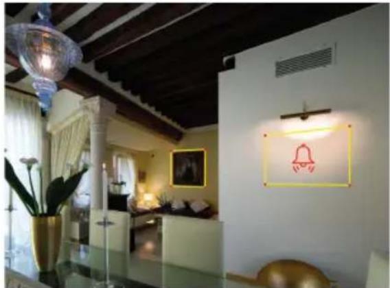
natural_image
Interior view of a modern living room with wooden ceiling, white walls, and decorative lighting (no visible text or symbols)natural_image
Dark indoor scene with illuminated furniture and plants, no visible text or symbolsnatural_image
Interior view of a modern hotel lobby with chandeliers and seating (no visible text or signage)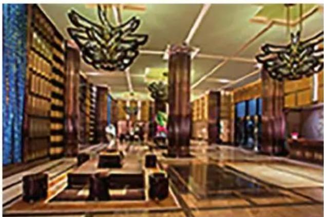
natural_image
Interior view of a grand hotel lobby with ornate wooden furniture and overhead chandelier lighting (no visible text or signage)natural_image
Interior of a grand hotel lobby with ornate ceiling lights and marble flooring (no visible text or signage)natural_image
Interior view of a futuristic, reflective corridor with high-rise buildings and hanging chandeliers (no visible text or symbols)5 - Interferenza
natural_image
Interior hallway with a black silhouette of a person walking, enclosed by red bounding boxes and a digital kiosk (no visible text or symbols)natural_image
Exterior night view of a modern hotel complex with palm trees, swimming pools, and illuminated windows (no signage or text visible)natural_image
Exterior view of a modern building with white structural elements and dark architectural details (no visible text or symbols)natural_image
Black-and-white photo of a vehicle under construction with bright headlights illuminating the engine (no visible text or symbols)natural_image
Crowd of people gathered outside a modern building at night, with no visible text or signagenatural_image
Crowded train station platform with multiple buses and passengers waiting, no visible text or signagenatural_image
Exterior view of a modern urban plaza with tall glass buildings and trees, silhouetted figures walking under a curved structure (no signage or text visible)natural_image
Crowded pedestrian crossing with checkered floor, many pedestrians walking (no visible text or signage)5.2.5 Ricerca del veicolo (Vehicle Search)
bar
| Event | Count | |---|---| | Day 2023/03/16 | 25 | | Week 2023/03/16 | 10 | | Month 2023/03/16 | 0 | | Quarter 2023/03/16 | 0 | | Customization 2023/03/16 | 0 | | Total: 2023/03/16 | | | | | | | | | | | | | | | | | | | | | | | | | | | | | | | | | | | | | | | | | | | | | | | | | | | Statistics Chart : Export5.5 Check-in Volto (Face Check-In)
- Installation requirements ....44
- Smart alarm avents 44
2.1 Abandoned or removed object....44
2.2 Exception detection....45
2.3 Line crossing/instruction detection....46
2.4 Face detection (NVR only)....48
- Video configuration analisys on DVR/NVR....51
3.1 Intelligence alarm....51
3.1.1 Object abandoned or removed....51
3.1.2 Exception....52
3.1.3 Tripwire....54
3.1.4 Intrusion area detection....55
3.1.5 Face Detection 57
- AI Event Management ....58
4.1 Face Recognition 58
4.1.1 Face Detection Settings 58
4.1.2 Face Database Management 59
4.1.3 Face Recognition Settings 62
4.2 Tripwire 63
4.3 Intrusion Detection 64
4.4 Abandoned/Missing Object Detection 64
4.5 Line Crossing Counting 65
4.6 Exception Detection 66
- Intelligent Analytics ....68
5.1 Target Detection View 68
5.1.1 Human Body/Vehicle Detection View 68
5.1.2 Face Detection / Match View 68
5.2 Smart Search 71
5.2.1 Face Search 71
5.2.2 Track Playback 75
5.2.3 Face Search by Snapshot 77
5.2.4 Human Body Search 77
5.2.5 Vehicle Search 78
5.2.6 Combination Search 79
5.3 View Statistical Information 79
5.4 Face Attendance 79
5.5 Face Check-In 81
DVR/NVR video analysis configuration
Introduction:
The video analysis includes all those functions, considered to be the evolution of the conventional motion detector, which use analytical algorithms to identify certain events within the scene, drastically reducing the number of false positive alarms generated.
This document aims mainly to describe some environmental and installation precautions for devices integrating video analysis functions to prevent malfunctions and limit the generation of false positive alarms.
1. Installation requirements
This series of network cameras support a lot of smart alarm function, such as object removal detection, exception detection, line crossing detection and region intrusion detection.
Before enabling the above-mentioned alarm functions, the following installation requirements must be met, in order to obtain the maximum benefit from the algorithm used to analyse the scene, improve the detection success rate and minimise malfunctions (false alarm, no alarm).
1) Cameras should be installed in settled places, lest too much shaking affects the accuracy of detection.
2) Avoid the reflective surfaces (like shiny floors, mirrors, glass, lake surfaces and so on).
3) Avoid narrow or too much shadowing monitoring places.
4) Avoid such monitoring scenario - the object color is similar to the background color. For example, a person in white walks in the snow. This will bring poor monitoring effect.
5) The monitoring images shouldn't have large changes after enabling the smart alarms, or it will result in frequency alarm triggers (for example, the auto focus function or automatic white balance is automatically enabled).
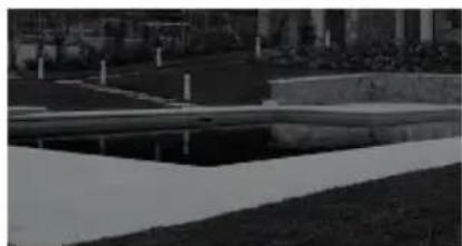
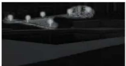
6) At any time of day or night, please make sure the image of cameras is clear and with adequate light, avoiding over-exposure or too dark on both sides of the scene. See the following pictures.
natural_image
Nighttime outdoor scene with illuminated structures and a large illuminated object (no visible text or symbols)
natural_image
Dark, low-contrast image of a paved outdoor area with no visible text or symbols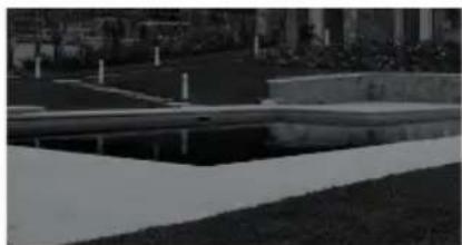
natural_image
Exterior view of a modern office building (no signage)- Uneven light, too dark on the left 2. Evenly distributed light 3. Sufficient light
2. Smart alarm events
2.1 Abandoned or removed object
This function is able to detect an abandoned or removed object in a pre-defined area within the frame perimeter. When detected the relative alarms are generated.
The alarm will be triggered when detecting the objects removed from the pre-defined area.
1) The range of the detection object occupies from 1/50 to 1/3 of the whole image.
2) The detection time of objects in the camera shall be from 3 to 5 seconds.
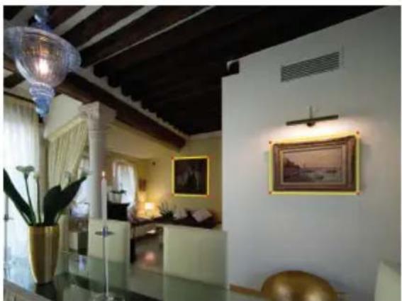
The defined area cannot be covered frequently and continuously (like people and traffic flow). is necessary for object removal detection that the drawn frame must be very close the margin of the object in enhancing the sensitivity and accuracy of the detection. See the following pictures.
natural_image
Interior view of a modern living room with wooden ceiling, framed artwork, and large glass table (no visible text or symbols)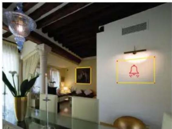
natural_image
Interior view of a modern living room with wooden ceiling, wall-mounted lighting, and decorative wall art (no visible text or symbols)Application Scenarios: object security, rubble flow, illegal parking detection, illegal posting of posters, defacement of building, etc.
DVR/NVR video analysis configuration
2.2 Exception detection
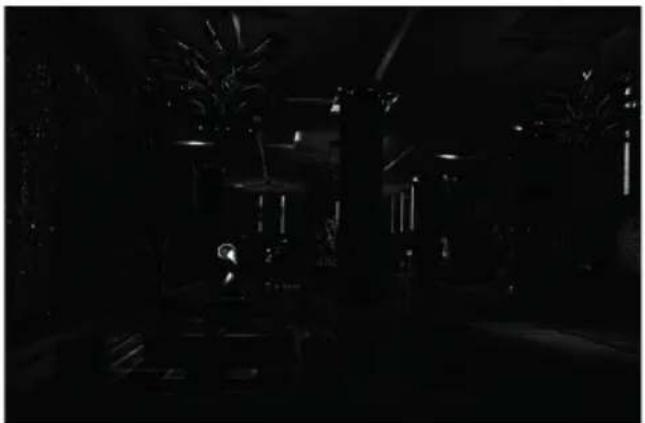
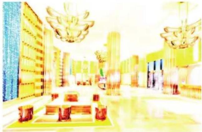
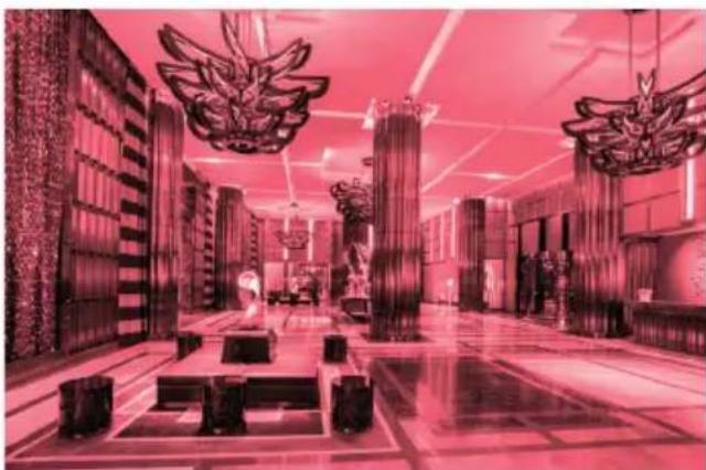
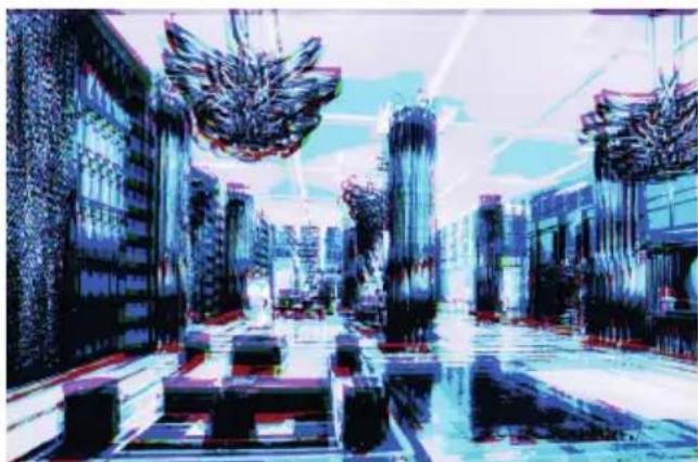
This function can detect the change of surveillance environment affected by the external factors and the blur and cast of the surveillance images and some certain actions can be taken when the alarm is triggered. Detect the exception of the image in the whole surveillance scene, including six kinds of exception events - low light, excessive brightness, low definition, color cast, interference and scene change. See the following pictures.
natural_image
Dark indoor scene with illuminated furniture and plants, no visible text or symbols1 - Low light 2 - Excessive brightness
natural_image
Interior view of a luxury hotel lobby with chandeliers and seating (no visible text or signage)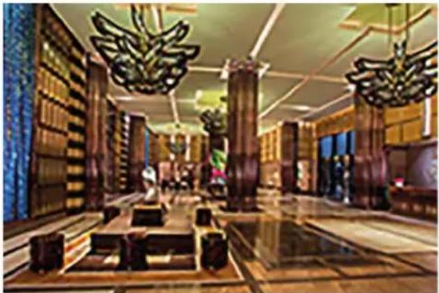
natural_image
Interior of a grand hotel lobby with ornate wooden furniture and large chandelier sculptures (no visible text or signage)3- Low definition
natural_image
Interior of a grand hotel lobby with ornate ceiling lighting and chandeliers (no visible text or signage)4 - Color cast
natural_image
Interior view of a modern, futuristic luxury or digital art space with reflective flooring and hanging ornaments (no visible text or symbols)5 - Interference
DVR/NVR video analysis configuration
2.3 Line crossing/instruction detection
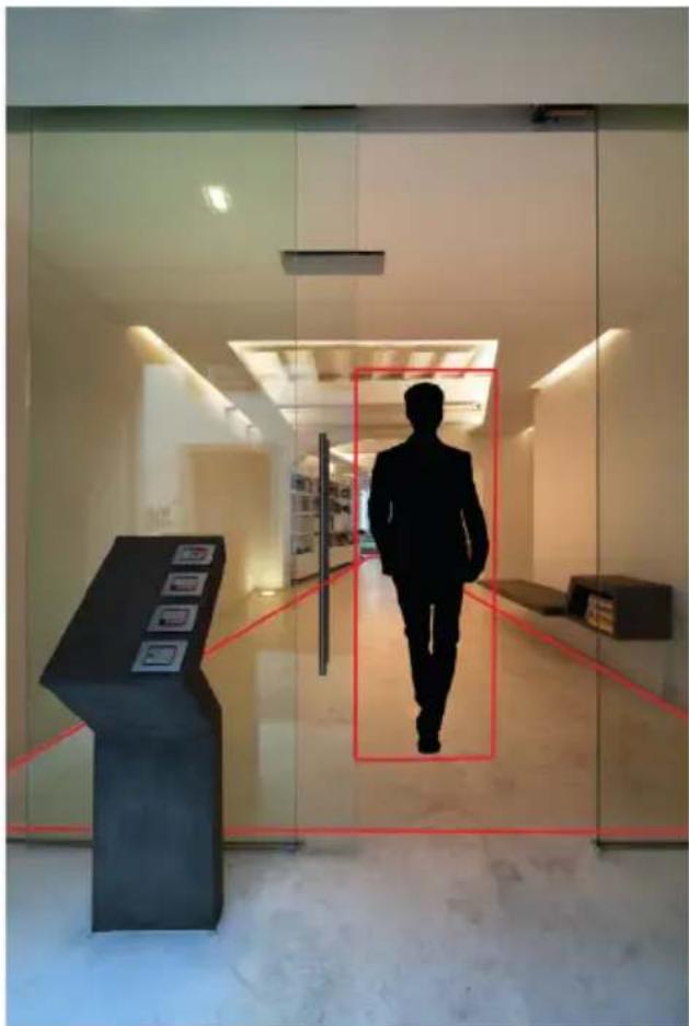
The relevant alarms will be triggered if someone or something crosses the pre-defined alarm lines or areas.
natural_image
Interior view of a modern glass building with a black silhouette of a person walking through the doorway, featuring a display stand and red measurement lines (no readable text or symbols)Line Crossing: detect the objects in the visual field and the alarms will be triggered when crossing the alarm lines toward positive or negative direction or both directions.
Region Intrusion: the alarms will be triggered when the objects in the visual field enter or leave the boundary of the area.
Installation requirement
1- Avoid the scenees with many trees or the scenes with many illumination changes (like many flasching headlights). The ambient brightness of the scenes shouldn't be too low, because dimply lighted scenes will decrease the accuracy of the alarm,
2- Cameras should be mounted at a minimum of 2,8 m
3- The mounting view angle of the camera tries to keep about 45°
4- The detected objects accounting for the proportion in the whole image should not be less than 1% and the largest sizes of the detected objects accounting for the proportion in the whole image should not be more than 1/8.
5- Make sure cameras can view objects for at least 2 second in the detected area for accurate detection.
DVR/NVR video analysis configuration
Inapplicable scenes
The accuracy of the intelligent video analysis is closely related to the complexity of the scenes. The following scenes are not applicable for intelligent video analysis is, which will decrease the accuracy.
natural_image
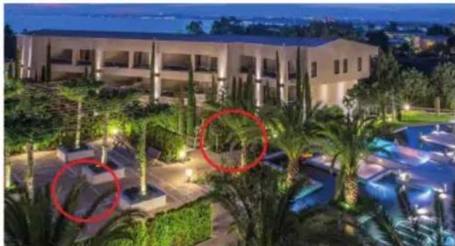
Exterior night view of a modern hotel complex with palm trees and illuminated swimming pools (no signage or text visible)1 - There are many trees in the monitoring scene. This circumstance is complex. When it's windy, the swaying branches of trees will cause interference. As a result, smart alarm functions inapplicable.
natural_image
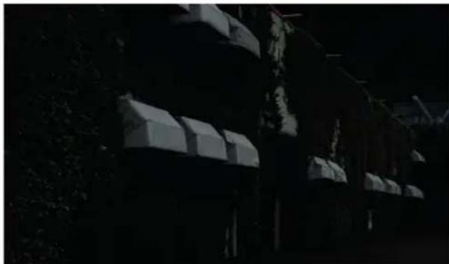
Exterior view of a modern building with arched windows and trees in the background (no visible text or symbols)2 - Scene with too low brightness
natural_image
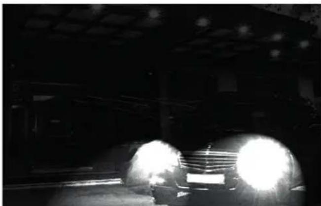
Black-and-white photo of a car with bright headlights illuminating the engine, no visible text or symbols3 - Scene with light changing frequently
natural_image
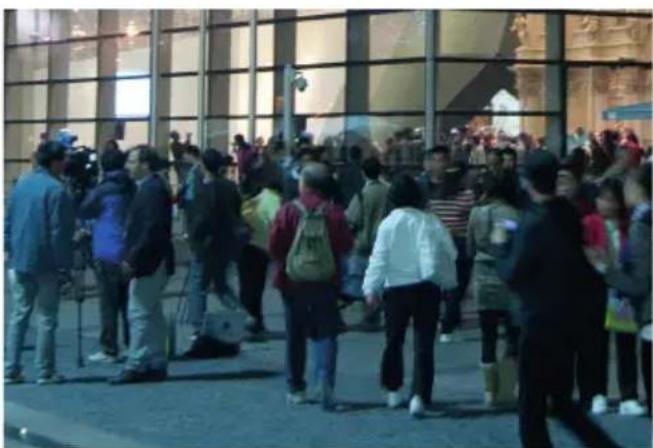
Crowd of people gathered outside a modern building at dusk, with no visible text or signage4 - Small mounting angle of depression (it is not available for line crossing and region intrusion detection)
Application scenarios:
Region Intrusion: this function can be applicable to important supervision places, danger areas and prohibited areas, like military administrative zones, house breaking, scenic high danger areas, no man's areas, etc.
Line Crossing: it can be used in electronic fence, warning line of flood prevention, parking lots, traffic instruction, etc.
DVR/NVR video analysis configuration
2.4 - Face detection (NVR only).
Face detection: this function allows you to recognize faces in the visual field, upon recognition, the NVR will be able to activate the related actions, such as recording, activating alarms, etc.
Installation requirements:
1 - The camera is installed in front of the channel, and capture the face from straight front.
2 - Installation height H is about 2.0 \~ 3.5 m (can be adjusted according to lens focus and capture distance).
3 - Camera depression angle α less than or equal to 15°.
4 - The capture distance D is adjusted according to the selected camera lens focus.
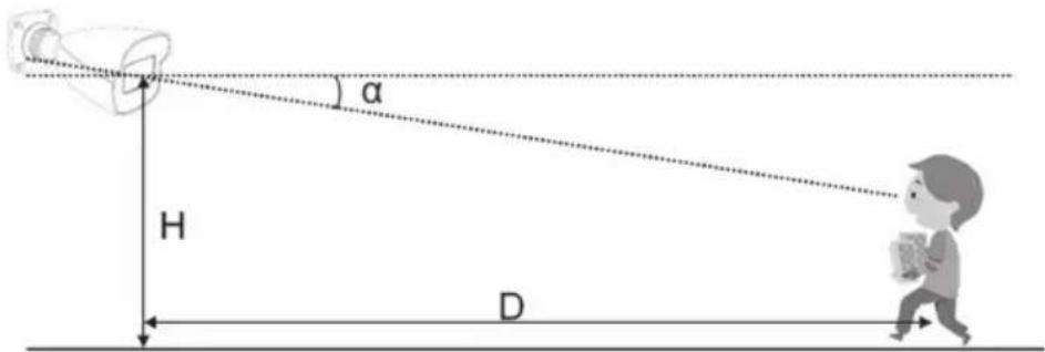
1 - In order to guarantee the captured face recognition rate, the requirement for face capture are:
- left or right face turn angle is less than about 30^ ,
- pitching angle is less than 20^ .
2 - Face illumination must be uniform, if the brightness is low or there is a large area of shadow, need to do the light filling.
3 - When the capture scenario is backlight, the camera's BLC/HLC/WDR need to be turned on, or fill the light.
4 - The face recognition do not support black & white mode for now.
| Monitoring width | Lens focus | Best capture distance | Installation height | Depression angle |
| 2.5 m 8 mm | 3.8 m 2.2 m | 10^ | ||
| 2.5 m 12 mm | 5.7 m 2.5 m | 10^ | ||
| 2.5 m 16 mm | 7.6 m 2.9 m | 10^ |
Remark: The lower the camera depression angle (that means the lower the installation height) we have, the better captured straight face we get.
Factors That Affect Capture & Recognition.
| Factors Image Explanation | ||
| Obscured face |  | Wearing sunglasses, mask, hat or face is being obscured by other objects, will cause no recognition at all. |
| Small face, side face |  | The screen size of the human face is less than 1/15 screen, which can not be captured.Face pitching angle is larger than 20°, left or right face turn angle is more than about 30°, will lead recognition rate reduced or no recognition at all. |
| Low brightness face |  | Low brightness face or face with large area of shadows, will cause low accurate recognition. |
DVR/NVR video analysis configuration
| Factors Image Explanation | ||
| Low resolution face | 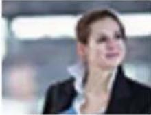 | Double image face, low resolution face will caused no recognition. |
| Black & white face | 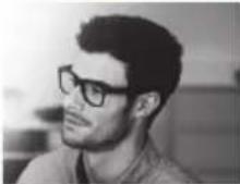 | The face recognition do not support black & white mode for now. |
Typical scenarios.
Indoor corridor installation.
| Install height 2.5 m | 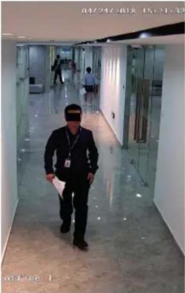 | |
| Install angle Depression angle about 7° | ||
| Install mode Ceiling mount. | ||
| Lens focus 12 mm | ||
| Capture distance 2 ~ 7 m | ||
| Screen occupation ratio | 8% ~ 20% | |
| Other | Corridor mode, white light compensation in straight front. | |
Overpass Installation.
| Install height 2.5 m | 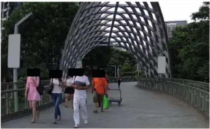 | |
| Install angle Depression angle about 10° | ||
| Install mode Ceiling Mode. | ||
| Lens focus 16 mm | ||
| Capture distance 2 ~ 10 m | ||
| Screen occupation ratio | 8% ~ 20% | |
| Other | Cloudy, white light compensation in straight front at night. | |
DVR/NVR video analysis configuration
Gates installation.
| Install height 2.5 m | 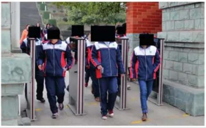 | |
| Install angle Depression angle about 10° | ||
| Install mode Ceiling Mode. | ||
| Lens focus 16 mm | ||
| Capture distance 2 ~ 10 m | ||
| Screen occupation ratio | 8% ~ 20% | |
| Other | Cloudy, white light compensation in straight front at night. | |
Not recommended scenarios.
Airport, train station, bus station, subway entrance and exit, square, hall and other large population density areas are not suitable for use..
Backlight scene, face brightness is too low, face cannot be detected, not suitable for use.
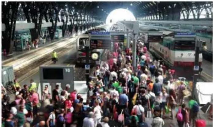
natural_image
Crowded train station platform with multiple buses and passengers waiting, no visible text or signage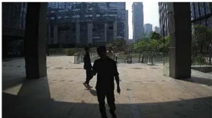
natural_image
Exterior view of a modern urban plaza with tall buildings and trees, silhouetted figures walking (no signage or text visible)At the intersection, the face pixel is too small and the shooting Angle is too big, is not suitable for use.
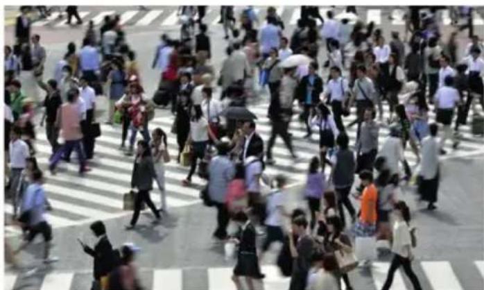
natural_image
Crowded pedestrian crossing with pedestrians and pedestrians on a city street (no visible text or signage)DVR/NVR video analysis configuration
3. Video configuration analisys on DVR/NVR
3.1 Intelligence alarm
3.1.1 Object abandoned or removed
Object detection configuration:
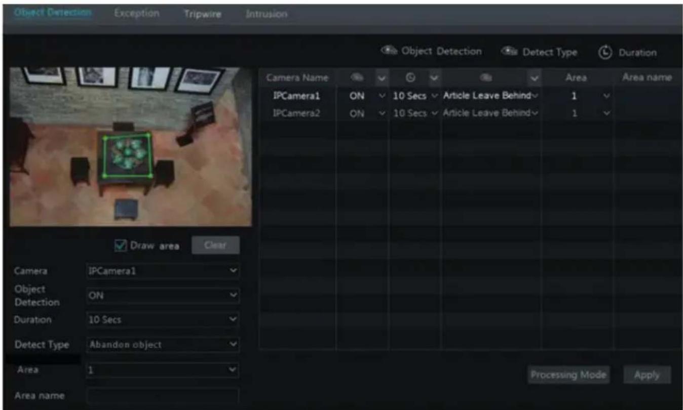
1) Click Start → Settings → Camera → Intelligent Detection → Object Detection to go to the following interface.
2) Select the camera, enable the object detection and set the duration and detect type.
There are two detect types: Abandon Object and Missing Object.
Abandon Object: The relevant alarms will be triggered if there are articles left in the detection area drew by the users.
Missing Object: The relevant alarms will be triggered if there are articles missing in the detection area drew by the users.
3) Select the warning area and input the area name. You can add 4 warning areas at most.
4) Draw the warning area of the object detection. Refer to the interface as shown above. Check "Draw Area" and then click around the area where you want to set as the warning area in the image (the warning area should be a closed area). Uncheck the "Draw Warning Area" if you finish the drawing. Click "Clear" button to delete the warning area.
5) Click "Apply" to save the settings.
6 Click "Processing Mode" to go to the alarm handling configuration interface of object detection.
Object detection alarm handling configuration:
1) Click Start → Settings → Alarm → Intelligence Alarm → Object Detection to go to the following interface.
DVR/NVR video analysis configuration
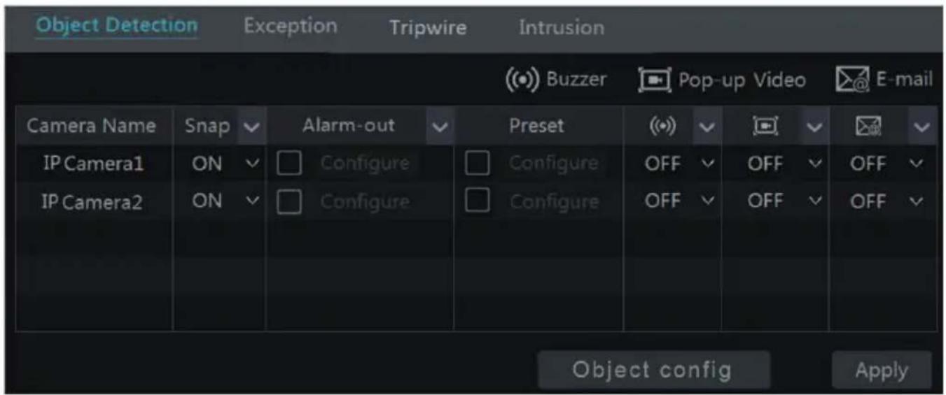
2) Enable or disable "Snap", "Alarm-out", "Preset", "Buzzer", "Pop-up Video" and "E-mail".
The alarm handling setting of object detection alarm is similar to that of the sensor alarm (see GUI full user manual, Sensor Alarm for details).
3) Click "Apply" to save the settings. You can click "Object Config" to go to the object detection configuration interface.
3.1.2 Exception
Exception Configuration:
1) Click Start → Settings → Camera → Intelligent Detection → Exception to go to the following interface.
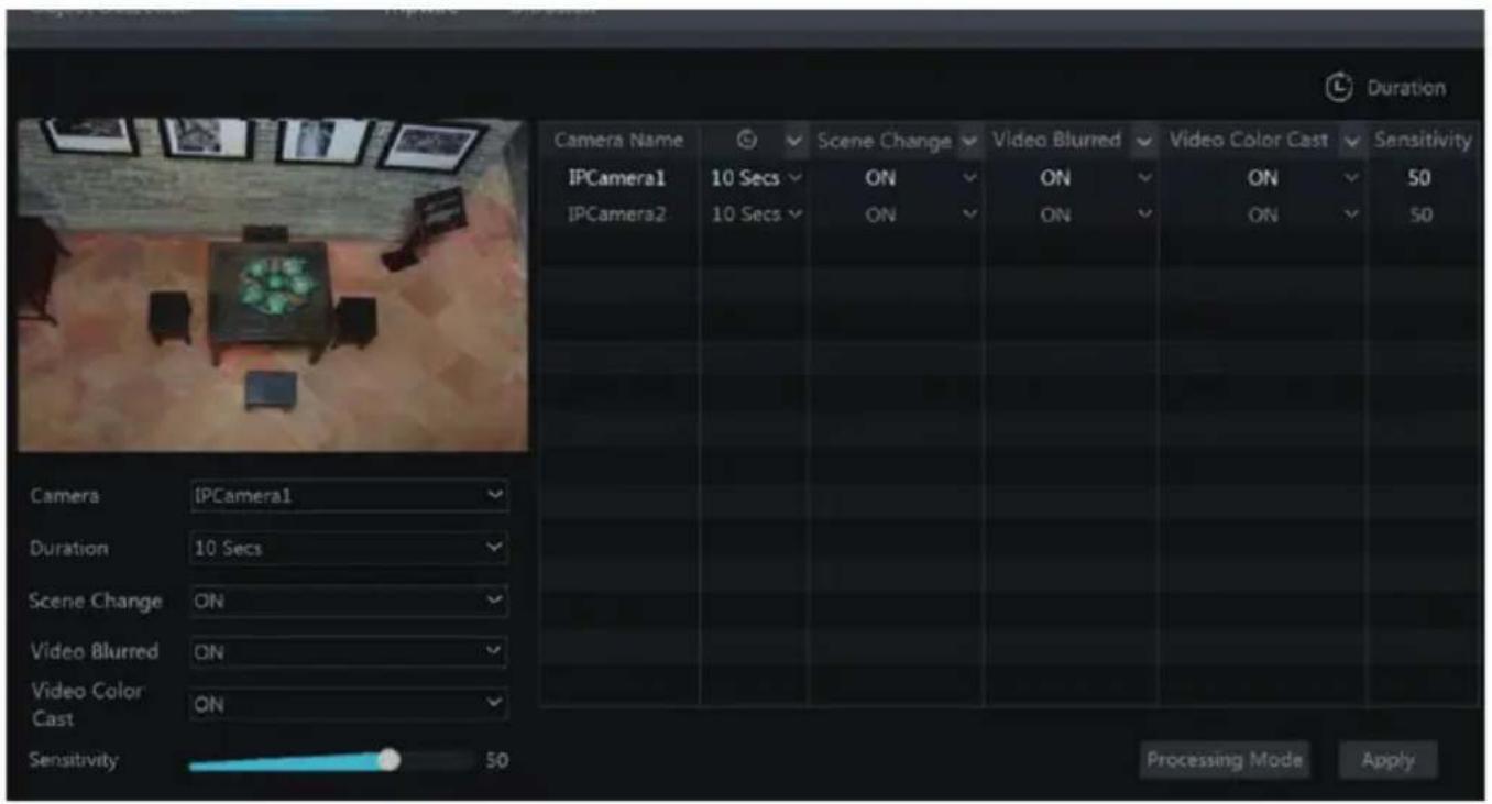
2) Select the camera and enable the relevant detection as required.
Scene Change: The relevant alarms will be triggered if the scene of the monitor video has changed.
Video Blurred: The relevant alarms will be triggered if the monitor video is blurred.
Video Color Cast: The relevant alarms will be triggered if color cast happens to the monitor video.
DVR/NVR video analysis configuration
3) Set the duration and drag the slider to set the sensitivity of the exception detection.
The sensitivity value of Scene Change Detection: the bigger the value is, the more sensitive the system responds to the amplitude of the scene change.
The sensitivity value of Video Blur Detection: the bigger the value is, the more sensitive the system responds to the defocus of the device image. You should just the value according to the real situation.
The sensitivity value of Video Color Cast Detection: the bigger the value is, the more sensitive the system responds to the color cast of the device image. You should also consider other factors.
4) Click "Apply" to save the settings.
5) Click "Processing Mode" to go to the alarm handling configuration interface of exception detection.
Exception alarm handling configuration:
1) Click Start → Settings → Alarm → Intelligence Alarm → Exception to go to the interface.
2) Enable or disable "Snap", "Alarm-out", "Preset", "Buzzer", "Pop-up Video" and "E-mail".
The alarm handling setting of exception detection alarm is similar to that of the sensor alarm (see 9.1 Sensor Alarm for details).
3) Click "Apply" to save the settings. You can click "Exception Config" to go to the exception detection configuration interface.
DVR/NVR video analysis configuration
3.1.3 Tripwire
Line Crossing Configuration:
The relevant alarms will be triggered if someone or something crosses the alert line drew by the users.
1) Click Start → Settings → Camera → Intelligent Detection → Tripwire to go to the following interface.
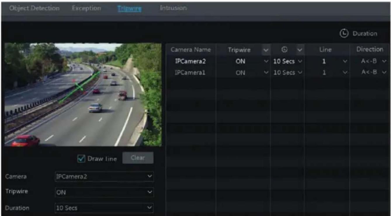
2) Select the camera, enable the tripwire detection and set the duration.
3) Select the line and direction. You can add 4 lines at most.
Direction:
A<->B, A->B and A<-B optional. It is the crossing direction of the intruder who crosses over the alert line.
A<->B: the alarm triggers when the intruder crosses over the alert line from B to A or from A to B.
A->B: the alarm triggers when the intruder crosses over the alert line from A to B.
A<-B: the alarm triggers when the intruder crosses over the alert line from B to A.
4) Draw the alert surface. Refer to the interface as shown above. Check "Draw line" and then drag the mouse in the image to draw an alert line. Uncheck the "Draw line" if you finish the drawing. Click "Clear" button to delete the alert line.
5) Click "Apply" to save the settings.
6) Click "Processing Mode" to go to the alarm handling configuration interface of line crossing detection.
DVR/NVR video analysis configuration
Line Crossing Alarm Handling Configuration:
1) Click Start → Settings → Alarm → Intelligence Alarm → Tripwire to go to the following interface.
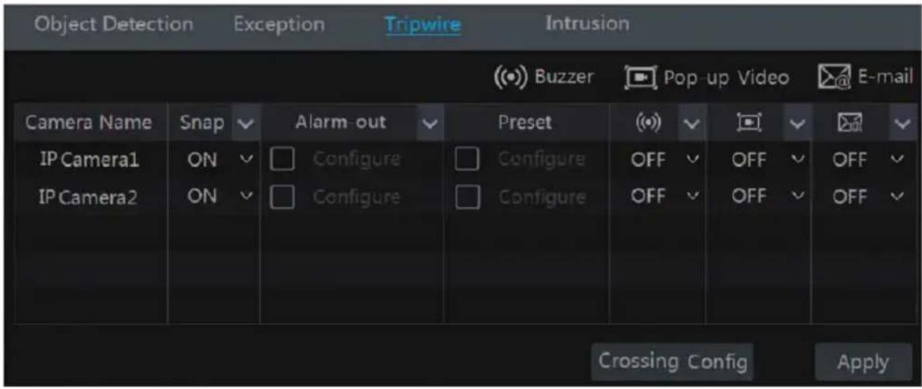
2) Enable or disable "Snap", "Alarm-out", "Preset", "Buzzer", "Pop-up Video" and "E-mail".
The alarm handling setting of line crossing alarm is similar to that of the sensor alarm (see GUI full user manual, Sensor Alarm for details).
3) Click "Apply" to save the settings. You can click "Crossing Config" to go to the line crossing configuration interface.
3.1.4 Intrusion area detection
Intrusion Configuration:
The relevant alarms will be triggered if someone or something intrudes into the warning areas or moves in the warning areas drew by the users.
1) Click Start → Settings → Camera → Intelligent Detection → Intrusion to go to the following interface.
2) Select the camera, enable the intrusion detection and set the duration.
3) Select the warning area. You can add 4 warning areas at most.
4) Draw the warning area of the intrusion detection. Refer to the interface as shown below.
Check "Draw area" and then click around the area where you want to set as the warning area in the image (the warning area should be a closed area). Uncheck the "Draw area" if you finish the drawing. Click "Clear" button to delete the warning area.
5) Click "Apply" to save the settings.
6) Click "Processing Mode" to go to the alarm handling configuration interface of intrusion detection.
DVR/NVR video analysis configuration
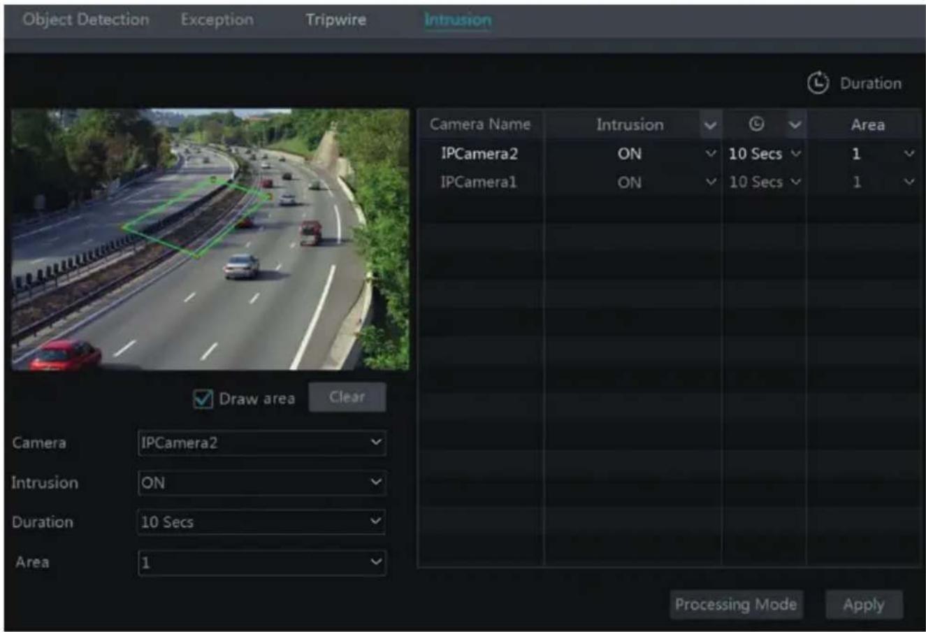
Intrusion detection alarm handling configuration
1) Click Start → Settings → Alarm → Intelligence Alarm → Intrusion to go to the following interface.
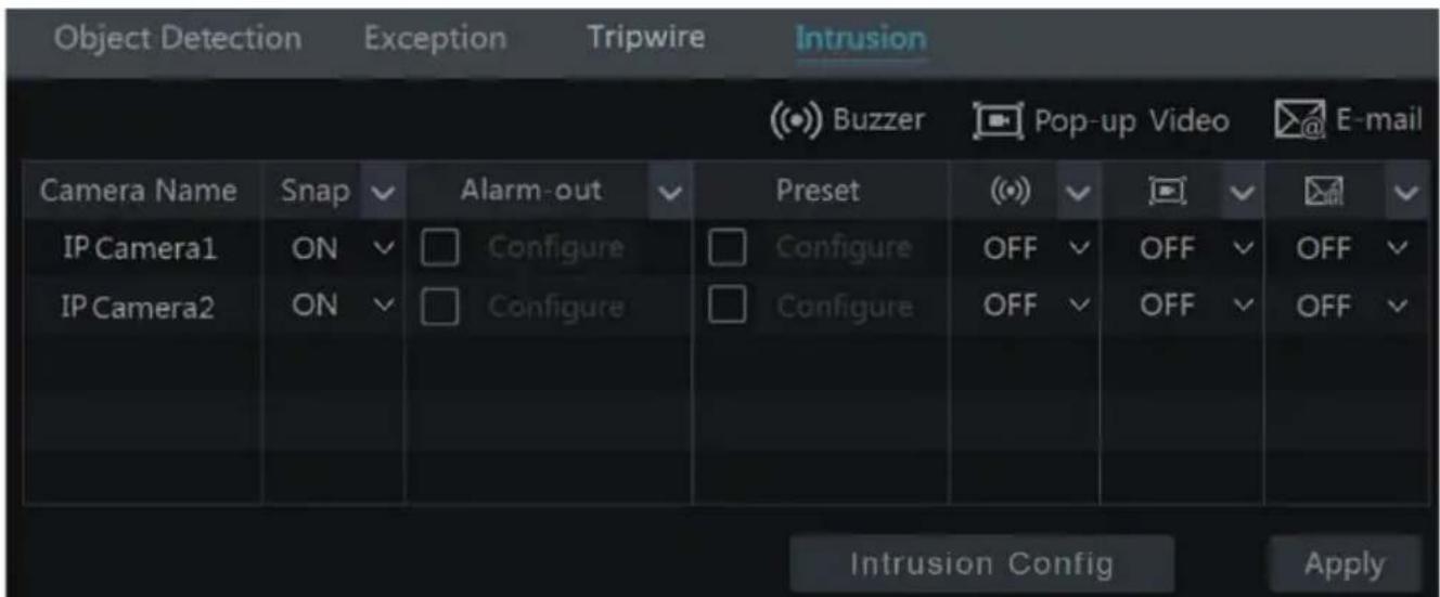
2) Enable or disable "Snap", "Alarm-out", "Preset", "Buzzer", "Pop-up Video" and "E-mail". The alarm handling setting of intrusion detection alarm is similar to that of the sensor alarm (see GUI full user manual, Sensor Alarm for details).
3) Click "Apply" to save the settings. You can click "Intrusion Config" to go to the intrusion detection configuration interface.
DVR/NVR video analysis configuration
3.1.5 Face Detection
Face Detection: Alarms will be triggered if target people intrude into the pre-defined alarm areas.
1 - Click Start → Settings → Camera → Smart Settings → Face Detection to go to the following interface.
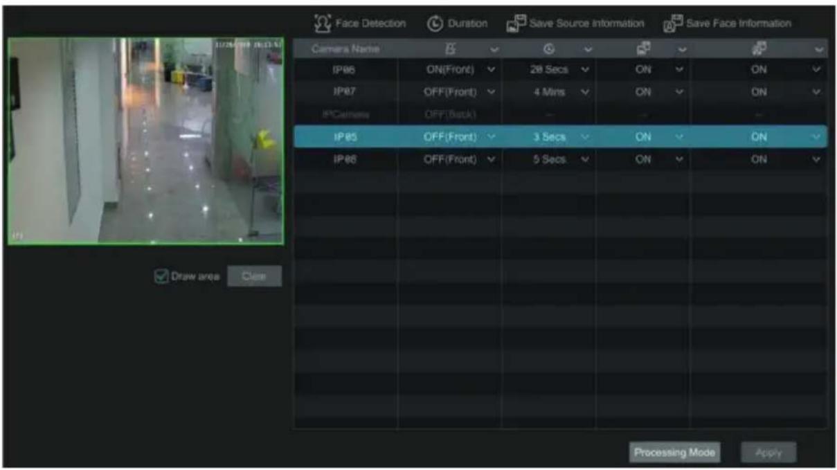
2 - Select the camera, enable the face detection and set the duration.
If the added cameras are face detection cameras, on (front) or off (front) can be selected.
3 - Enable save source information and save face information.
4 - Select the alarm area. Draw the alarm area of the intrusion detection. Refer to the interface as shown below. Check "Draw area" and then drag the mouse to draw a detection area. Click "Clear" to Delete the alarm area.
5 - Click "Apply" to save the settings.
6 - Click "Processing Mode" to go to the alarm handling configuration interface of face detection.
Face Detection Alarm Handling Configuration:
1 - Click Start → Settings → Alarm → Face Detection to go to the following interface.
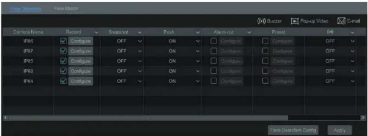
2 - Enable or disable "Snapshot", "Push", "Alarm-out", "Preset", "Buzzer", "Pop-up Video" and "E-mail". The alarm handling setting of face detection alarm is the same as the sensor alarm.
Click "Apply" to save the settings. You can click "Face Detection Config" to go to the face detection configuration interface.
4 AI Event Management
4.1 Face Recognition
Important: Only some models support the face recognition function. If your device doesn't support this function, please skip the following steps.
Please set face recognition function according to the following procedures:
Set face detection and alarm linkage → Add face group → Add faces to the face group → Enable and set successful recognition (or stranger) → Set successful recognition (or stranger) alarm linkage
4.1.1 Face Detection Settings
Face Detection: Alarms will be triggered if someone intrudes into the pre-defined alarm areas.
1) Click Start → Settings → AI/Event → AI Event → Face Recognition → Detection to go to the following interface.
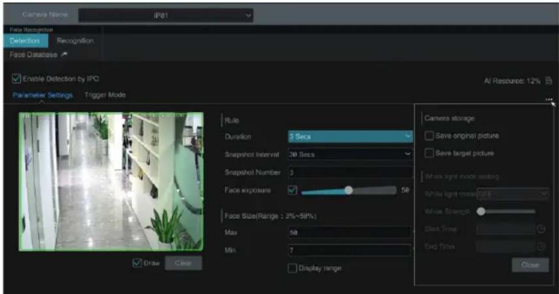
2) Select the camera, check "Enable Detection by IPC" and set the duration.
Note: Some models may support face detection by NVR. For these models, the camera without AI function also can be added and used to detect faces through NVR. But if face detection by NVR is enabled for one camera (without AI), the people/vehicle perimeter detection cannot be enabled simultaneously, and vice-versa.
3) Set the snapshot interval and snapshot number. The snapshot interval refers to the time interval that the camera captures the same face during its continuous tracking period. The snapshot number refers to the picture number of the same face captured during its continuous tracking period (For example: the snapshot interval is set to "30 seconds" and the snapshot number is set to "3"; then the camera will capture the same face once every 30 seconds and it will capture this face 3 times at most during its continuous tracking period).
4) Enable face match exposure as need. When the brightness of the captured face is not enough, it can be enabled. (Only some IPCs support this function)
5) Set the alarm area. Click "Draw" and then drag the mouse to draw a detection area. Click "Clear" to delete the alarm area. Then set the detectable face size by defining the maximum value and the minimum value (The default size range of a single face image occupies from 3% to 50% of the entire image).
6) Enable "Save Source Information" or/and "Save Face Information" as needed. If enabled, the system will automatically save the corresponding images on the SD card. For the models with LED light, white light mode also can be set.
7) Click "Apply" to save the settings.
8) Click "Trigger Mode" to go to face detection alarm linkage setting interface:
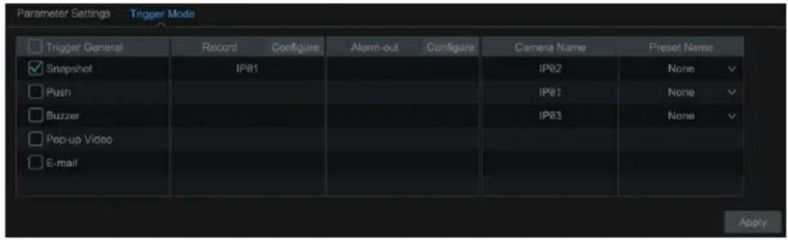
Face Detection Alarm Linkage Configuration:
- Trigger "Record", "Snapshot", "Push", "Alarm-out", "Preset", "Buzzer", "Pop-up Video" and "E-mail" as needed.
Record: Click the "Configure" button to pop up the window. Select camera on the left side and then click

to set the camera as the trigger camera. Select trigger camera on the right side and then click to cancel the trigger camera. Click "OK" to save the settings. The trigger cameras will record automatically when faces are detected.
Alarm-out: Click the "Configure" button to pop up the window. Then the "Trigger Alarm-out" window will pop up automatically. Configure the trigger alarm-out in the window. The system will trigger the alarm-out automatically when faces are detected. You need to set the delay time and the schedule of the alarm outputs.
Preset: Click ▼ and then select the preset for each camera.
Snapshot: check it. The current camera will capture images automatically when faces are detected.
Push: If it is enabled, the system will send messages when faces are detected.
Buzzer: if it is enabled, the system will begin to buzz when faces are detected.
Pop-up Video: if it is enabled, the system will pop up the corresponding video automatically when faces are detected.
E-mail: if it is enabled, the system will send an e-mail when faces are detected. Before you enable the email, please configure the recipient's e-mail address first.
Enable "IPC_Audio" or "IPC_Light" as needed (only some IPCs support these two functions).
9) Click "Apply" to save the settings.
4.1.2 Face Database Management
1) Click Start → Settings → AI/Event → AI Event → Face Recognition → Face Database to go to the following interface as shown below.
For the first time, you can click "+" or "Add Group" to add groups.
2) To add targets for each group.
- Select a list and then click to expand the list as shown below.
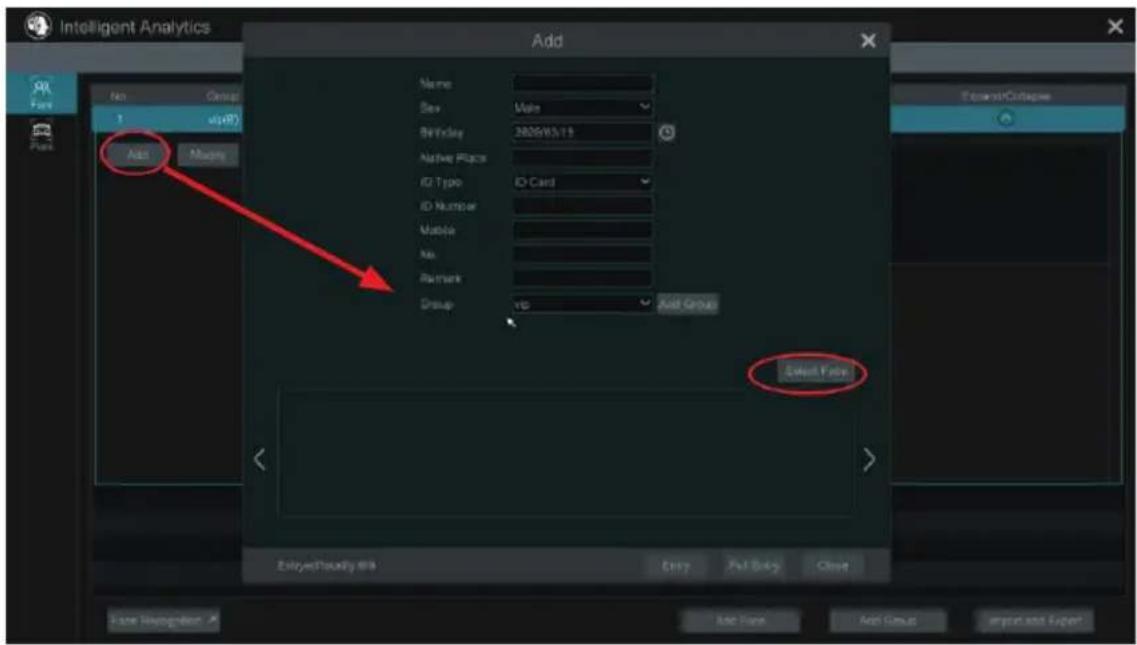
- Click "Add" and then click "Select Face" to add face images. You can add faces from snapshot gallery or external faces.
Adding faces from snapshot gallery: Select search time or self define the search time and then click "Search" to search target faces. Then select the desired faces and click "Select".
Save the face pictures in your USB storage device and then insert the USB storage device into the USB port of the NVR.
Go to the face database interface. Click expand the group and then click "Add". Select "External faces" to select face pictures. You can select one face to add or multiple faces to add.
To add multiple faces: a. put face pictures and the description file (.csv or .txt) to one specific folder (please edit the detailed descriptions of these pictures according to the personal information description); b. click "All" to select all face pictures; c. click "Full Entry".
Note: the added image must be less than 70KB and the image format shall be ".jpg" and ".jpeg".
• After that, add the corresponding information, like name, gender, birthday, ID number, phone number and so on.
Having saved the target image, click the image and then the detailed information will be listed on the right.
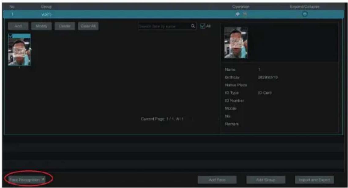
- Import and Export Face database Insert your mobile storage device into the USB interface of the NVR and then click "Import and Export" to import or export the face database settings.
4.1.3 Face Recognition Settings
After the face database and face pictures are added, click "Face Recognition" to return to the face recognition setting interface. Click the "Recognition" tab to go to the following interface.
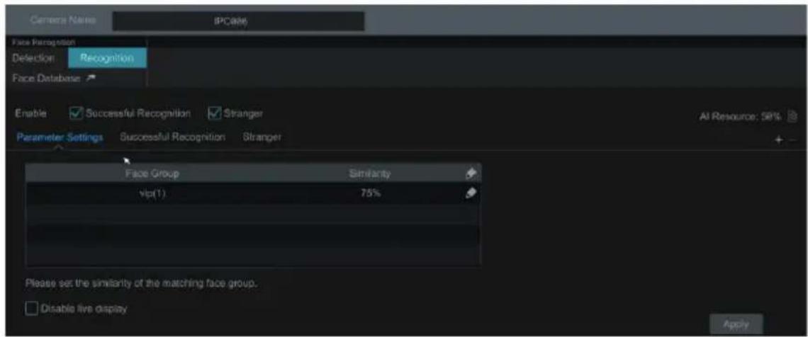
1) Enable "Successful Recognition" or "Stranger". Click "Parameter Settings" to set the similarity of the matching face group.
Disable live display: if checked, the live view interface (target detection tab) will not display captured faces in real time.
2) Set the alarm linkage items of successful recognition.
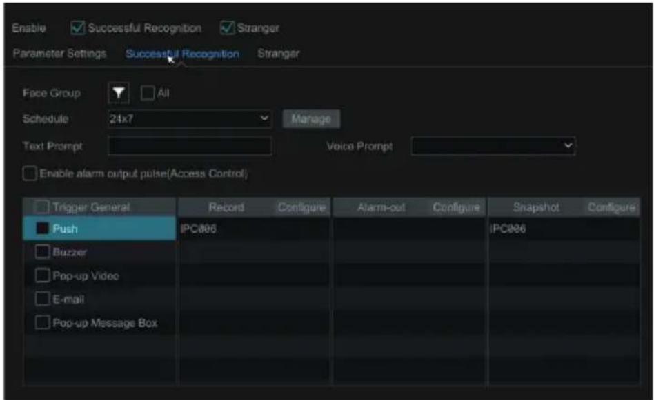
- Select one or more face groups and then choose the schedule. Click "Manage" to set the schedule.
• Text prompt and voice prompt not supported. - Enable alarm output pulse (access control).
- Trigger record, snapshot, alarm-out, buzzer, push, pop-up video, E-mail and pop-up message box as needed. The alarm linkage settings are similar to the face detection alarm (see 4.1.1 Face Detection Settings for details).
- Click "Apply" to save the settings.
3) Set the stranger alarm linkage items. When the captured face picture doesn't match the face pictures in the face database or their similarity is lower than the set value, the captured person will be regarded as a stranger.
- Configure the schedule
• Text prompt and voice prompt not supported. - Trigger record, snapshot, alarm-out, buzzer, push, pop-up video, E-mail and pop-up message box as needed. The alarm linkage settings are similar to the face detection alarm (See 4.1.1 Face Detection Settings for details).
- Click "Apply" to save the settings.
4) Click "+" to add more successful recognition tasks. Select the added task and then click "-" to delete it.
4.2 Tripwire
Tripwire/Line Crossing Configuration:
Alarms will be triggered if the people or vehicles cross the pre-defined alarm line.
1) Click Start → Settings → AI/Event → AI Event → Tripwire to go to the following interface.
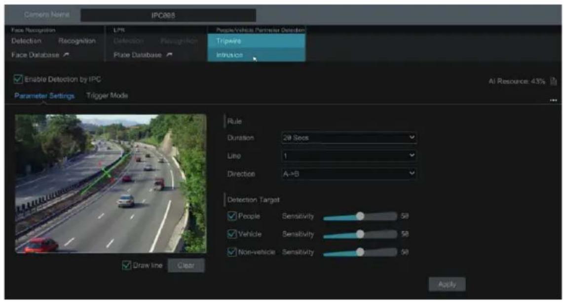
2) Select the camera, enable tripwire detection by IPC and set the duration.
Note: Some models may support tripwire detection by NVR.
3) Select the direction.
Direction: A<->B, A->B and A<-B optional. It is the crossing direction of the target that crosses over the alert line.
A<->B: the alarm triggers when the target crosses over the alert line from B to A or from A to B.
A->B: the alarm triggers when the target crosses over the alert line from A to B.
A<-B: the alarm triggers when the target crosses over the alert line from B to A.
4) Draw line. Refer to the interface as shown above. Check "Draw line" and then drag the mouse in the image to
draw an alert line. Uncheck the "Draw line" if you finish the drawing. Click the "Clear" to delete the alert line.
5) Click "Detection Target" to choose the detection target and the sensitivity. The detection target includes people, vehicle and non-vehicle. Only some IPCs can detect human or vehicle separately. If the camera doesn't support this function, please skip this step.
6) Click “...” to choose “Save original picture” or “Save target picture” on the SD card of the camera. (If your camera doesn’t support this function, please skip this step).
7) Click "Trigger Mode" to configure tripwire alarm linkage items.
- Enable or disable "Record", "Snapshot", "Push", "Alarm-out", "Preset", "Buzzer", "Pop-up Video" and "E-mail". The alarm linkage settings are the same as the face detection alarm (see 4.1.1 Face Detection Settings for details).
- Enable "IPC_Audio" or "IPC_Light" as needed (functions not supported by cameras).
8) Click "Apply" to save the settings.
4.3 Intrusion Detection
Intrusion Detection Configuration:
Alarms will be triggered if the people or vehicles intrude into the pre-defined area.
1) Click Start → Settings → AI/Event → AI Event → Intrusion to go to the following interface.
2) Select the camera, enable the intrusion detection by IPC and set the duration.
Note: Some models may support tripwire detection by NVR.
3) Select regional activities. "Appear" or "Cross" can be selected (if your camera doesn't support region entrance/ exiting detection, "Cross" will not be enabled). If "Cross" is selected, you can choose the crossing direction.
4) Select the alarm area. Up to 4 alarm areas can be set up.
5) Draw the alarm area of the intrusion detection. Refer to the interface as shown below. Check "Draw Area" and then click around the area where you want to set as the alarm area in the image (the alarm area should be a closed area). Uncheck the "Draw Area" if you finish the drawing. Click the "Clear" to delete the alarm area.
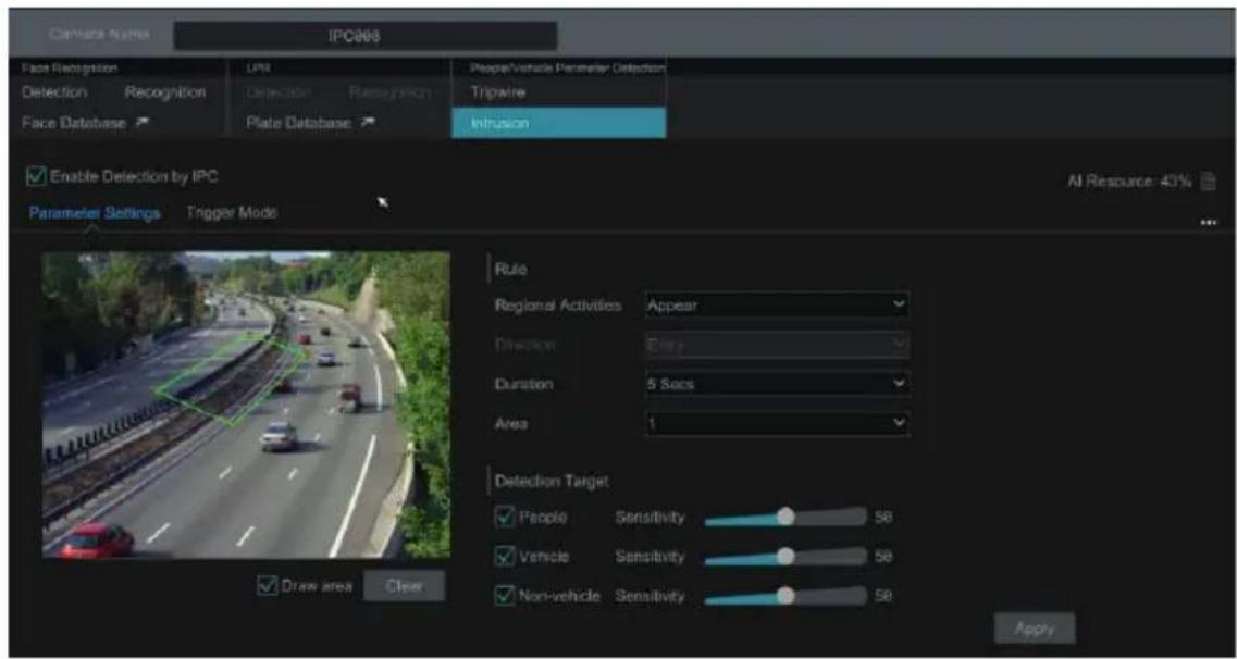
6) Click "Detection Target" to choose the detection target and the sensitivity. The detection target includes people, vehicle and non-vehicle.
7) Click "Trigger Mode" to configure intrusion detection alarm linkage items.
- Enable or disable "Record", "Snapshot", "Push", "Alarm-out", "Preset", "Buzzer", "Pop-up Video" and "E-mail". The alarm linkage settings are the same as the face detection alarm (see 4.1.1 Face Detection Settings for details).
- Enable "IPC_Audio" or "IPC_Light" as needed (functions not supported by cameras).
8) Click "Copy To" to copy all settings to other cameras.
9) Click "Apply" to save the settings.
4.4 Crowd Density Detection
Only some IPCs may support this function.
Crowd Density Configuration:
Alarms will be triggered if the crowd density exceeds the set threshold value in the pre-defined area.
1) Click Start → Settings → AI/Event → AI Event → Crowd Density to go to the following interface.
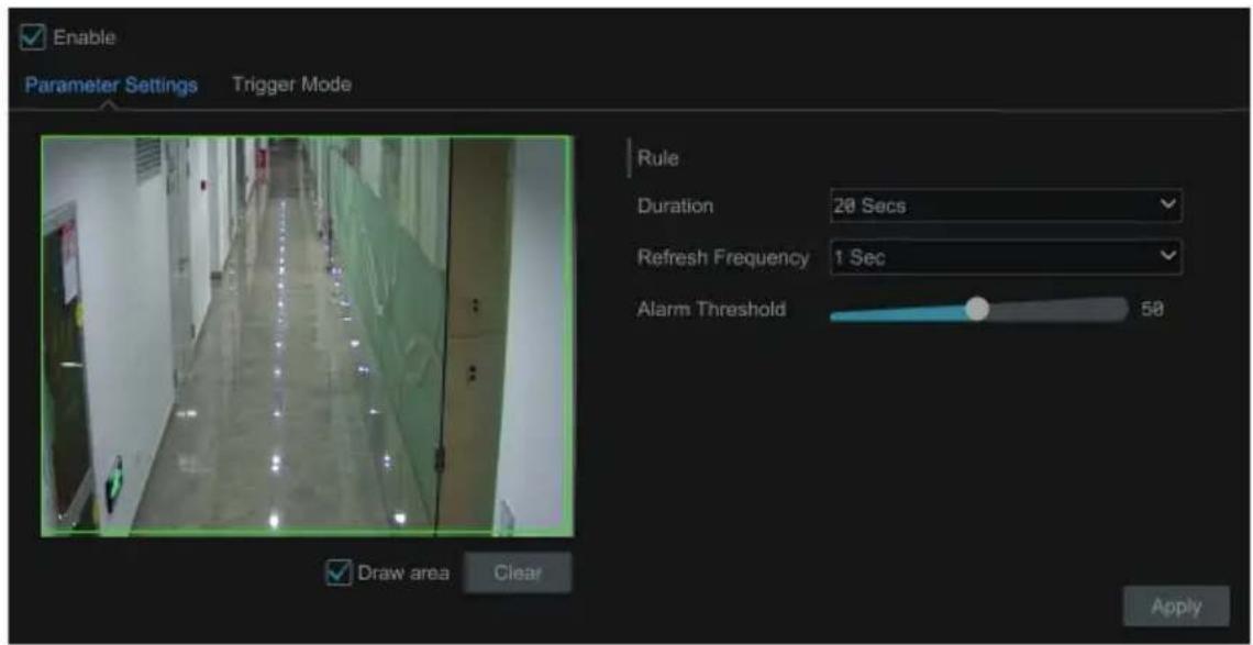
2) Select the camera, enable the crowd density detection and set the duration, refresh frequency and alarm threshold.
Refresh Frequency: It refers to the refresh time of the detection result report.
Alarm Threshold: Alarms will be triggered once the percentage of the crowd density in a specified area exceeds the pre-defined threshold value.
3) Select the alarm area. Draw the alarm area of the crowd density detection. Refer to the interface as shown below. Check "Draw Area" and then drag the mouse to draw a rectangle area. Uncheck the "Draw Area" if you finish the drawing. Click the "Clear" to delete the alarm area.
4) Click 📄 to configure crowd density detection alarm linkage items. Enable or disable "Record", "Snapshot", "Push", "Alarm-out", "Preset", "Buzzer", "Pop-up Video" and "E-mail". The alarm linkage settings are the same as the face detection alarm (see 4.1.1 Face Detection Settings for details).
5) Click "Apply" to save the settings.
4.5 Line Crossing Counting
Only some IPCs may support this function.
• People counting in the pre-defined area:
This function is to calculate the number of people entering or exiting in the detected area on the video by detecting, tracking and counting the head shapes of people.
Note: Only some specific IPCs may support this function.
1) Click Start → Settings → AI/Event → AI Event → Line Crossing Counting to go to the following interface.
2) Select the camera, enable the line crossing people counting detection and set the duration, sensitivity, statistic cycle, enter threshold, departure threshold and retention threshold.
Statistic cycle: Always, daily, weekly and monthly are optional.
Manual Reset: The current number of people counting will be cleared and the statistic cycle will restart by clicking "Manual Reset" button.
3) Set the alarm area and entrance direction. Click "Draw Area" and drag the mouse to draw a rectangle area. Drag the rectangle to change its position. Uncheck the "Draw Area" if you finish the drawing. Click "Clear" to clear the area. Click and drag the arrow or the other end of the arrow line to change the people entrance direction.
6) Click "Apply" to save the settings.
• Line Crossing People/Vehicle/Non-Vehicle Counting
Only some IPCs support this function. If your camera doesn't support this function, please skip the following instructions.
1) Click Start → Settings → AI/Event → AI Event → Line Crossing Counting to go to the following interface.
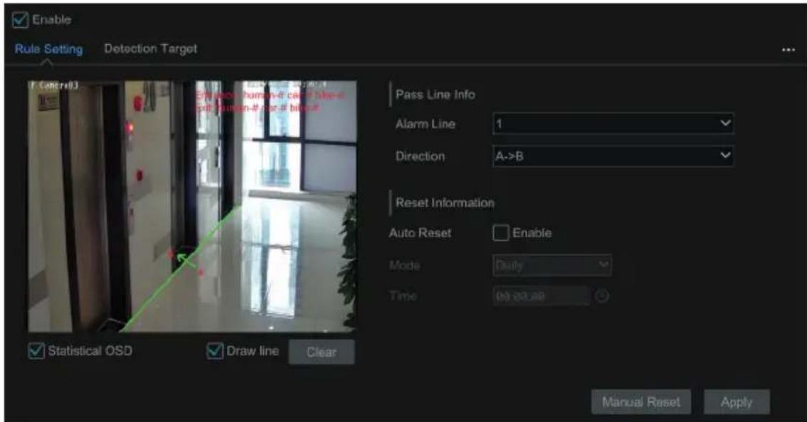
2) Enable line crossing counting.
3) Check "Draw line" and then drag the mouse on the small window to draw the crossing line.
Uncheck "Draw line" to finish the drawing. Click "Clear" to delete the alert line.
Direction: A->B and A<-B are optional. It is the crossing direction of the target that crosses over the alert line.
4) Check "Statistical OSD", the statistical information will be displayed on the live view interface.
5) Set the reset information. You can set reset information manually or enable "Auto Reset" as needed.
6) Click the "Detection Target" tab to set the detection target, including people, vehicle and non-vehicle.
7) Click "Apply" to save the settings.
4.6 Exception Detection
Exception Detection Configuration:
1) Click Start → Setting → AI/Event → AI Event → Exception Detection to go to the following interface.
2) Select the camera and detection duration and then enable the relevant detection as needed.
Scene Change: Alarms will be triggered if the scene of the monitor video has changed.
Video Blurred: Alarms will be triggered if the video becomes blurry.
Video Color Cast: Alarms will be triggered if the video becomes obscured.
3) Set the sensitivity of the exception detection.
4) Click "Trigger Mode" to configure exception alarm linkage items. Enable or disable "Record", "Snapshot", "Push", "Alarm-out", "Preset", "Buzzer", "Pop-up Video" and "E-mail". The alarm linkage settings are the same as the face detection alarm (see 4.1.1 Face Detection Settings for details).
5) Click "Apply" to save the settings.
5.1 Target Detection View
Only some models support target detection view. If your device doesn't support it, please skip the following instructions.
5.1.1 Human Body/Vehicle Detection View
Only when the camera supports human body/vehicle detection, can you view the real-time captured people or vehicle pictures. The setting steps are as follow:
1) Enable the Tripwire/Intrusion function of IPCs/NVR, draw the line or area and choose the detection target (see 4.2 Tripwire and 4.3 Intrusion Detection for details).
2) Go to live view interface and then click 📄 to go to the target detection interface of this channel. In this interface, you can switch the channel on the top right. You can also click 📄 on the top right corner of the live view interface and then choose the target detection tab to go to the target detection interface of multi-channel as shown below. Click the captured picture on the right of the live interface to see the snapshot detailed information, such as snapshot time, camera, event type and target type.
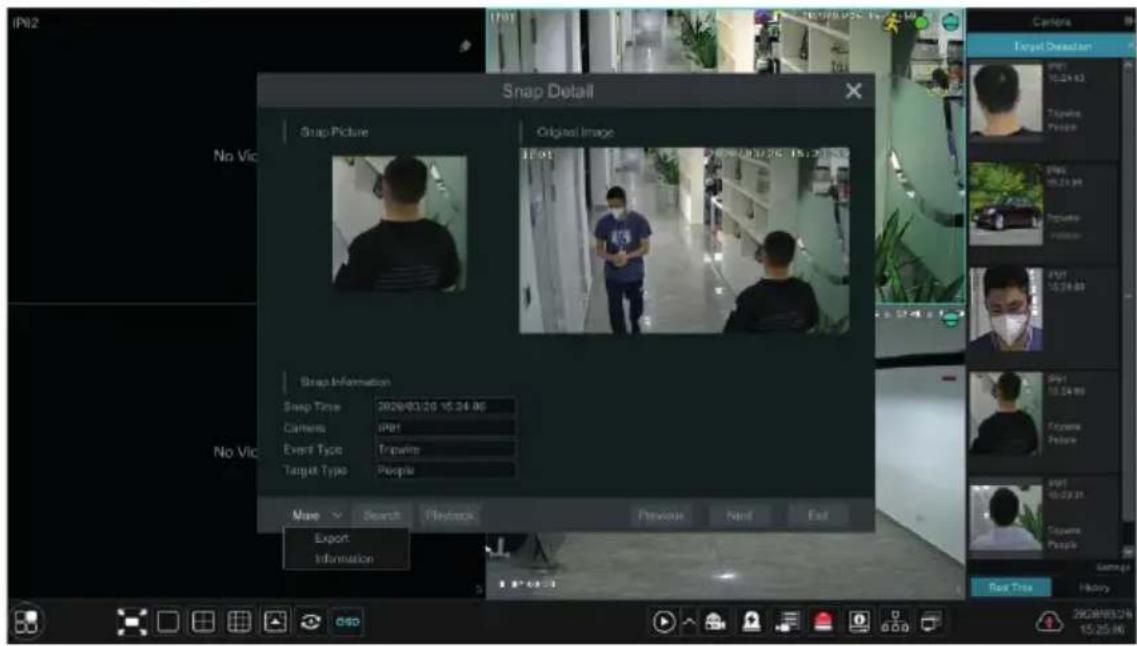
Click "More" to bring up a dropdown list. You can export the captured pictures by clicking "Export" or view the target ID by clicking "Information". Click "Search" to go to smart human body/vehicle search interface. The system will automatically search captured people/vehicles. Click "Playback" to go to the playback interface.
5.1.2 Face Detection/Match View
Only the face recognition NVR supports the following functions. If your NVR doesn't support them, please skip the following instructions.
The setting steps are as follow:
1) Enable face detection function.
2) Enable face recognition function and set the alarm linkage items.
3) Go to live view interface and click on a face detection channel.
This will bring a toolbar under the channel. Then click 📄 to go to the target detection interface of this channel. In this interface, you can switch the channel on the top right. You can also click 📄 on the top right corner of the live view interface and then choose the target detection tab to go to the target detection interface of multi-channel as shown below.
For unknown faces, you can select this face and click 🧑 under the captured face to register this face (see the following picture); click 🔒 to quickly go to the smart face search interface where you can search the matching face information; click ▶ to quickly go to the smart face playback interface; click 🧑 view snapshot details.
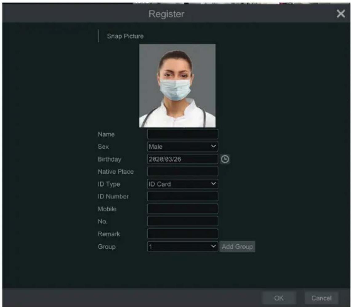
Before registering target face pictures, please add groups for them in advance.
After the face pictures are registered, the system will compare them automatically once the corresponding faces are captured next time. Refer to the following picture.
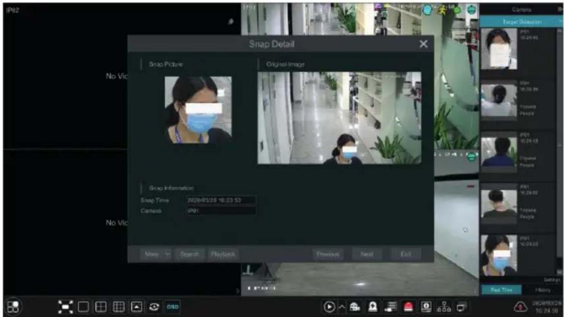
Double click the face picture to see the snapshot details, such as snapshot picture, original image, snapshot time and camera. Click "more" and then a dropdown list will display. Click "Register" to register the current snapshot. Click "Search" to go to face search interface. Click "Playback" to go to the playback interface. Click "Export" to export this snapshot details. Click "Information" to view face ID.
In the face match interface, click "Settings" to pop up the following window.
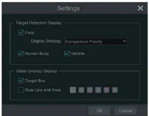
Target Detection Display: Face, human body and vehicle can be enabled. If disabled, the captured target picture will not be displayed under the target detection tab in the live view interface.
Display Strategy: Two options-Comparison priority and only comparison
Video Overlay Display:
If "Target box" is clicked, you will see the target traced by a little red box.
If "Rule Line and Area" is checked, you will see the rule line of tripwire detection and detection area of intrusion detection displayed on the screen. You can select the color of the rule lien and area as needed.
When the captured face pictures are successfully recognized, click the picture on the right to pop up a face detail window as shown below. In this window, you can see the captured face picture, the matched picture of face library and the relevant information. You also can view the original image, search image by snapshot, play back by snapshot and export the face details by clicking "More" button.
Additionally, you can view the historical captured face pictures and face match information in the face match interface by clicking "History" tab. Besides registering face pictures in the live view interface, you can also add target face pictures in the face database interface.
5.2 Smart Search
5.2.1 Face Search
Only some models support this function. If your device doesn't support it, please skip the following instructions.
Face Search by Event
1) Click Start → Intelligent Analytics → Search → Face to go to the following interface.
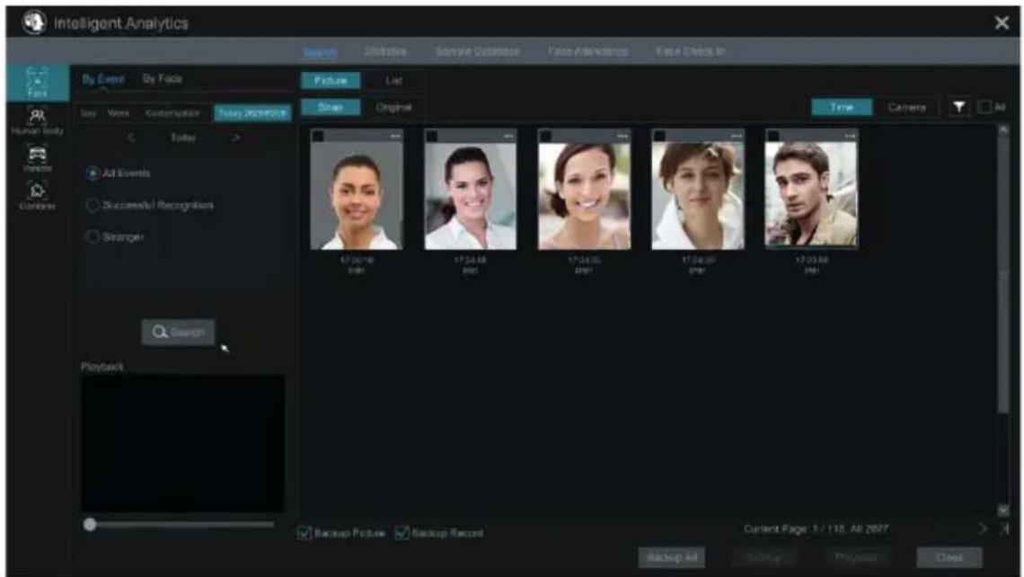
2) Click to choose face detection cameras.
3) Select all events, successful recognition or stranger.
4) Click "Search" to search face pictures. You can view face pictures by time or by camera.
5) Click the searched face picture to play in the small playback window; select a face picture and click "Backup" to export it.
Click "Original" to see the original image as shown below.
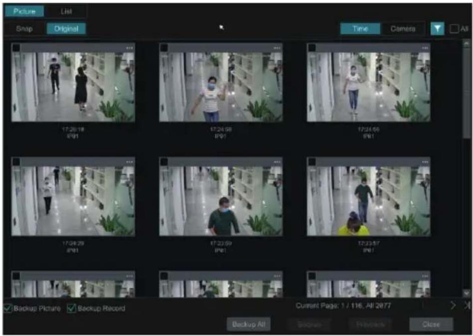
Click "List" to view the snapshot information list. Click view the detail information; click to book up the image.
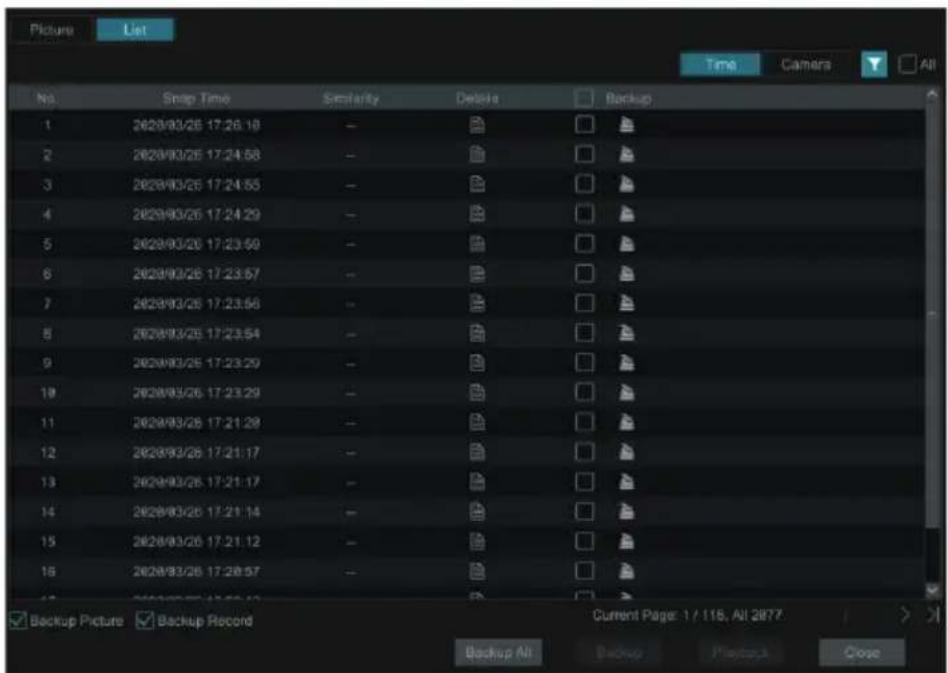
Face Search by Face
In the face picture search interface, click "By Face" to go to the following interface.
1) Click + to add the target face which can be searched and added from recent, face database, snapshot gallery
and external faces. A single face picture or multiple face pictures can be added and searched. (Take a single face picture for example)
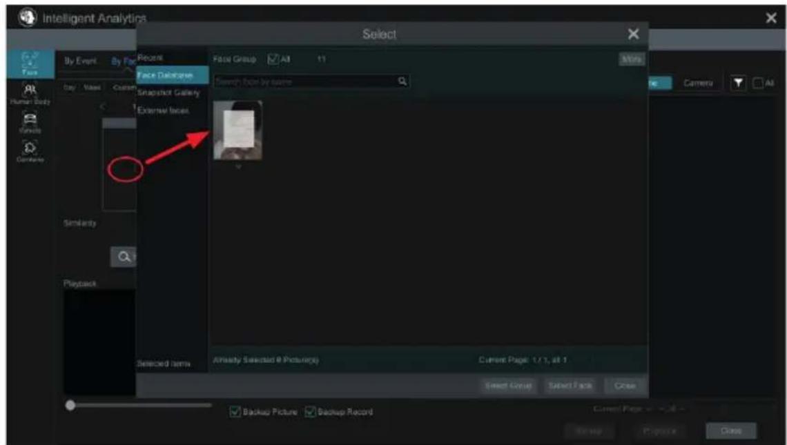
To add target face from recent
a. Choose the face.
b. Click "Select Face".
To add target face from face database:
a. Click "More" to choose groups.
b. Select a target face and click "Select Face".
To add target face from snapshot gallery:
a. Select time and click "More" to choose cameras.
b. Click "Search".
c. Check a face and click "Select Face".
To add target face from external face:
a. Save the target face to the mobile storage device and then insert this device into the USB interface of NVR.
b. Select "External Face" to import the face in this interface.
2) Set similarity and then click "Search".
3) Click the searched image to play records in the small window.
4) Select the searched image and click "Backup Picture" or "Backup Record". Then click "Backup" to build backups for pictures or records.
• View Image by List
Click "List" tab to view images by time as shown below.
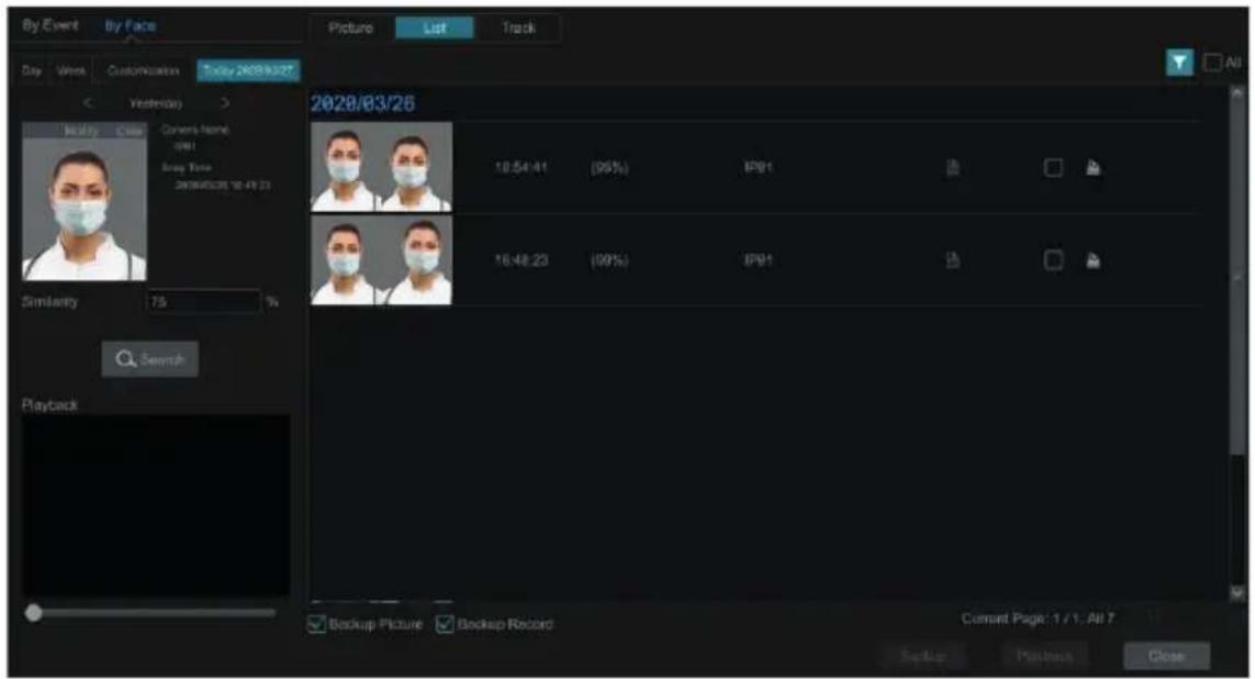
Click the searched image to play. Click to view the detail information of the compared target face.
• View Match Images
Click "Match" tab to view match images as shown below.
5.2.2 Track Playback
Select "Track" to go to the following interface.
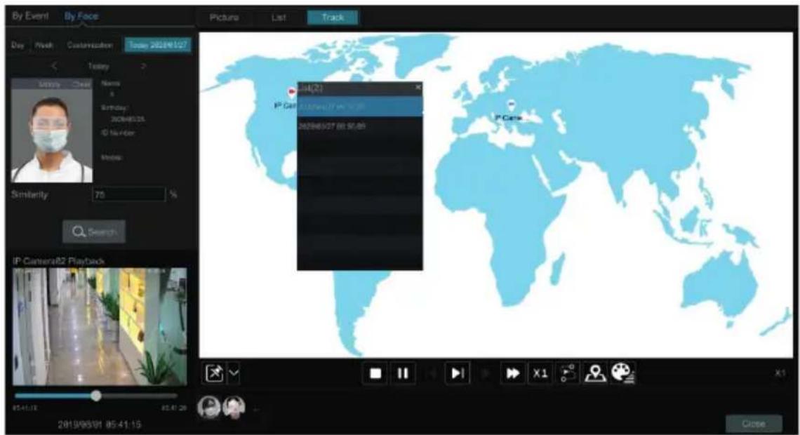
Note: Only when two or more cameras detect this person, can his/her track can be viewed here.
Descriptions of buttons on the track interface
 | Fixed Window Frame | ||
 | Followed Window Fast Forward (x2 x4) | ||
 | Exchange Window Normal Speed | ||
 | Stop Start/Stop Track | ||
 | Play Edit Map |
 | Previous Edit Color |  | |
 | Next |
Click on the camera name and then an event list appears. Click one item to play the record.
Click button beside the fixed window icon to show "Followed Window" and "Exchange Window" icons. The small playback window will float on the map window by clicking "Followed Window" as shown below.
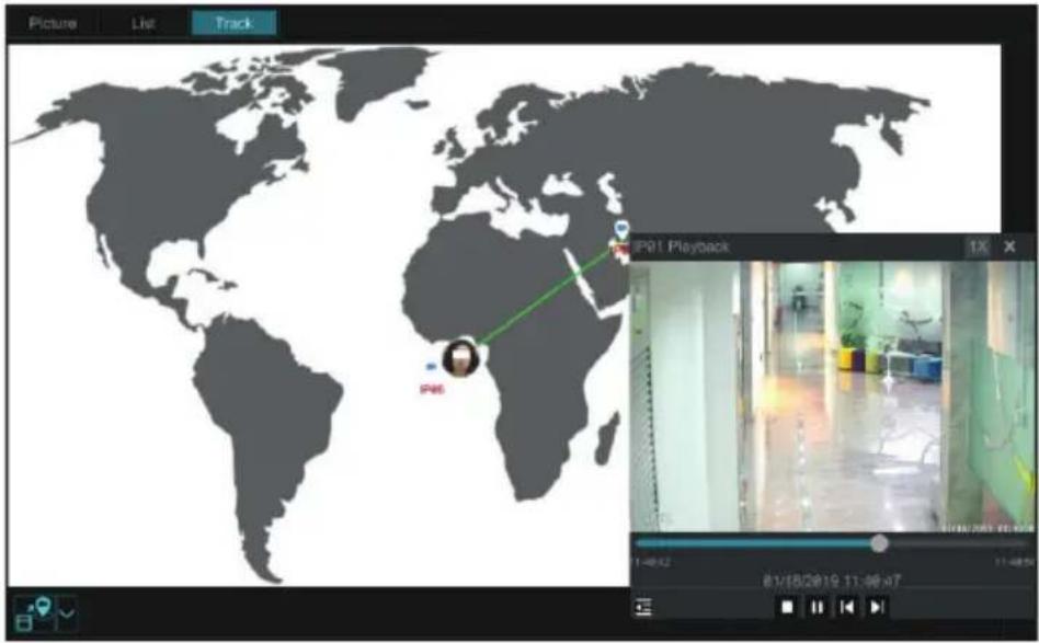


Click to switch play speed. 1x and 2x can be switched. Click to view event list. Click one item to play this event.
Click "Exchange Window" to switch the position of the map window and the playback window.
Click 📄 button to go to the following interface.
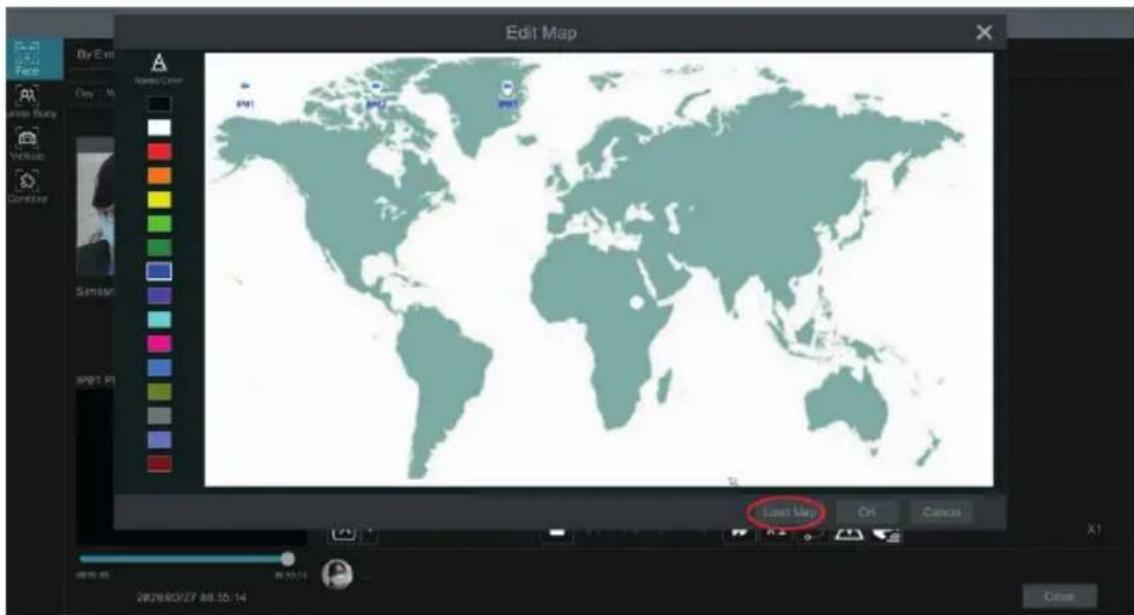
Click "Load Map" to add a map. Then drag the camera names on the map to change their locations. Choose a color on the left color list to set your favorite color for camera names.
Load Map:
1) Save the map to the USB storage device and then insert the USB storage device into the NVR.
2) Click "Load Map" button to upload the map.

button to modify the colors of camera name and track line and set the line width.
5.2.3 Face Search by Snapshot
In the live or playback interface, click on a face detection camera and then select the toolbar. This will bring the following window.
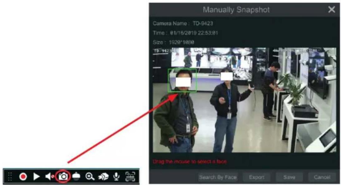
Drag the mouse to select a face and then click "Search by Face" to go to the face search by face interface. You can see its snapshot pictures, match pictures, original pictures and so on by clicking the corresponding tab.
5.2.4 Human Body Search
Click Start → Intelligent Analytics → Smart Search → Human Body to go to the human body search interface. Select the search time, camera and event and then click "Search" to view the searched pictures.
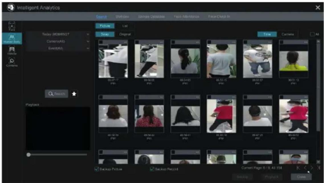
Click the searched picture to play the record in the small window. Select pictures and check "Backup Picture" and/or "Backup Record" and then click "Backup" to back up the pictures and /or records. Click "Original" to view the captured
original pictures. Click "List" to view the file list of the captured pictures.
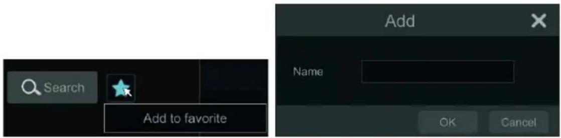
Click and select "Add to favorite" to add a favorite group and save the current searched pictures to the favorite group. Then you can quickly view these figure pictures by clicking and choosing the group name.
5.2.5 Vehicle Search
1) Click Start → Intelligent Analytics → Smart Search → Vehicle to go to the vehicle search interface.
2) Select the time, camera, event and vehicle type. Then click "Search" to search vehicles.
Event: Intrusion, Tripwire, Line Crossing Counting.
License plate recognition not supported.
Attribution: Vehicle or non-vehicle can be selected.
You can view face pictures by time or by camera.
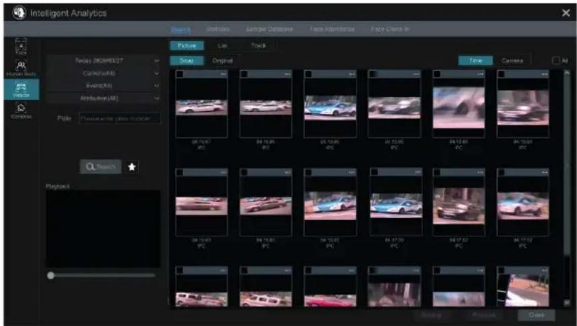
Click a searched vehicle picture to play it in the small window. Select vehicle pictures and check "Backup Picture" and/or "Backup Record" and then click "Backup" to back up the pictures and/or records.
3) Click "Original" to see the original pictures; click "List" to view the snapshot information list. Click 📄 to view the detail information; click 📋 to back up the image.
NOTE: License plate recognition not supported.
Click 🙏 to add a favorite group and save the current searched pictures to the favorite group. Then you can quickly view these vehicle pictures by clicking 🙏 and choosing the group name.
5.2.6 Combination Search
If you want to view the human body, vehicle or face pictures simultaneously, you can choose combination search.
2) Select the search time, camera, event and vehicle as needed.
Click a searched picture to play it in the small window. Select pictures and check "Backup Picture" and/or "Backup Record" and then click "Backup" to back up the pictures and /or records.
Click 📂 to add a favorite group and save the current searched pictures to the favorite group. Then you can quickly view these pictures by clicking 📂 and choosing the group name.
5.3 View Statistical Information
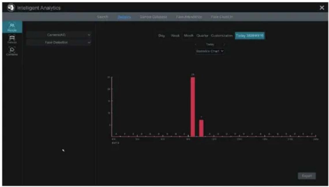
Click Start → Intelligent Analytics → Statistics to go to the following interface. In this interface, you can view the people and vehicle statistical information or you can customize the statistical information.
bar
Intelligent Analytics | Time | Value | |---|---| | 09:10-10 | 0 | | 10:00-10 | 0 | | 11:00-11 | 0 | | 12:00-13 | 0 | | 13:00-14 | 0 | | 14:00-15 | 0 | | 15:00-16 | 0 | | 16:00-17 | 0 | | 17:00-18 | 0 | | 18:00-19 | 0 | | 19:00-20 | 0 | | 20:00-21 | 0 | | 21:00-22 | 0 | | 22:00-23 | 0 | | 23:00-24 | 0 |View People Information:
Note: The person information includes face information and figure information.
1) Select the time.
2) Select cameras.
3) Select events as needed, such as face detection, face recognition, intrusion, tripwire, etc.
Note: Face recognition events (successful recognition & stranger) are available for some models. If Face Recognition-Successful Recognition event is selected, you can choose "Detail Chart" to view.
View Vehicle Information:
- Click "Vehicle"
- Select the time and cameras.
- Select events as needed.
- Select the vehicle attribution.
To customize statistical information:
Click "Combine" and then select events, people and vehicle as needed.
5.4 Face Attendance
This function is only available for some models. If your device doesn't support it, please skip the following instructions. Click Start → Intelligent Analytics → Face Attendance to go to the following interface.
To search attendance information
1) Click behind camera and group to choose the desired cameras and groups.
2) Set the attendance date. You can choose day, week, month and today or customize the time period.
3) Set the start time and the end time of working.
4) Click "Search" to view the attendance state.
If some specific person's attendance state needs to know, you can click "Advanced" and then enter the name and choose the type.
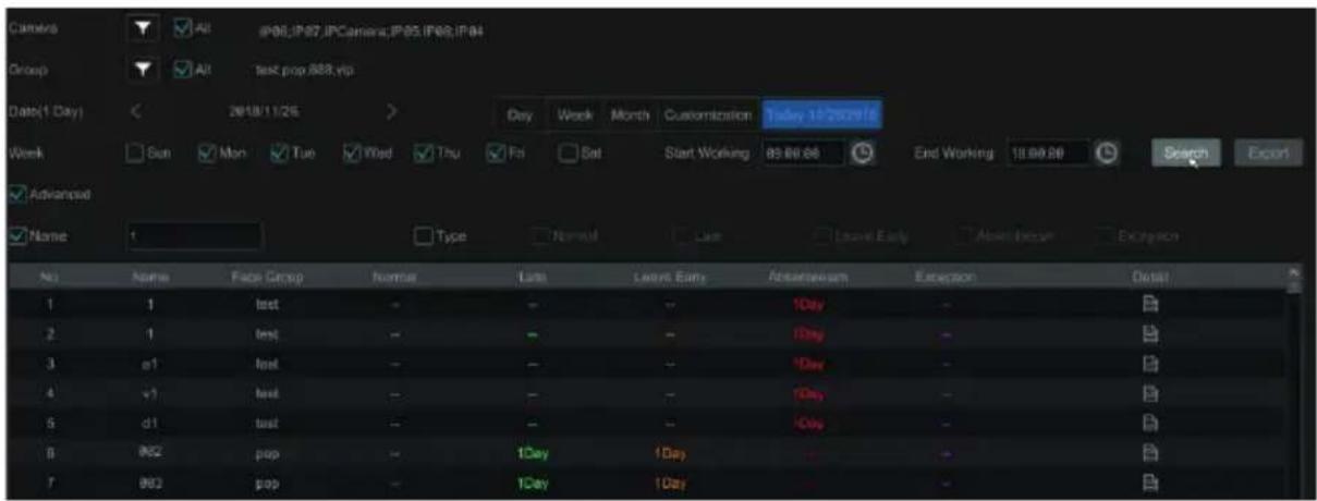
Click "Export" to export the searched attendance information.
Click to view the detailed information of attendance. In this interface, click go to the face search interface.
5.5 Face Check-In
Click Start → Intelligent Analytics → Face Attendance to go to the following interface.
The search steps of face check-in are as follows.

behind camera and group to choose the desired cameras and groups.
2) Set the check-in date. You can choose day, week, month and today or customize the time period.
3) Set the start time and the end time of face check-in.
4) Click "Search" to view the check-in state.
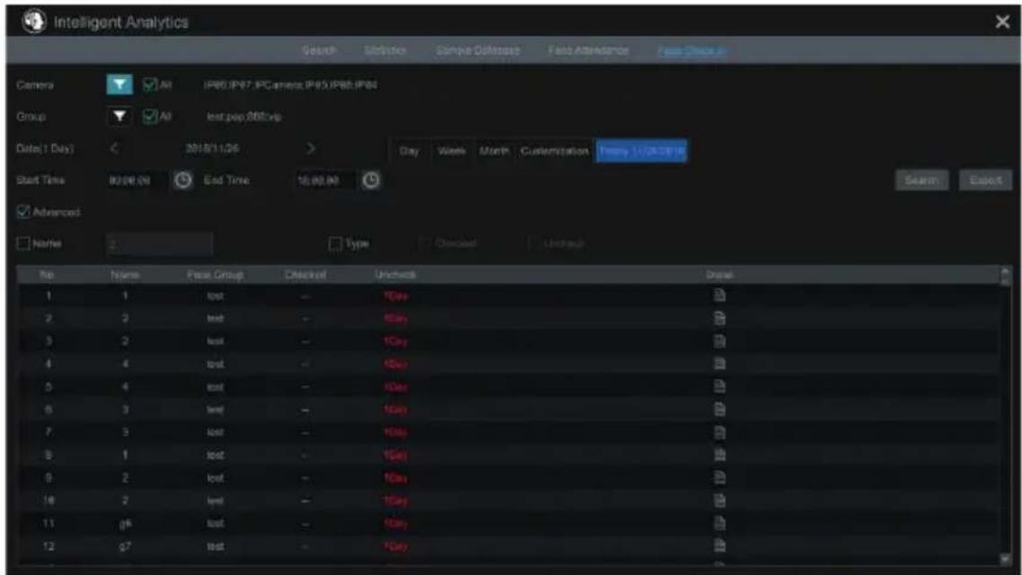
If you want to know the detailed check-in information of someone, please click "Advanced" and then enter the name and choose the type to search.
Click to view the detailed information. In this interface, the checked image can be viewed. Click to view the registered face picture of this person.

- Ricerca del veicolo (Vehicle Search)
- Check-in Volto (Face Check-In)
- DVR/NVR video analysis configuration
- Introduction:
- Installation requirements
- Smart alarm events
- Abandoned or removed object
- Exception detection
- Line crossing/instruction detection
- Installation requirement
- Inapplicable scenes
- Application scenarios:
- - Face detection (NVR only).
- Installation requirements:
- Typical scenarios.
- Not recommended scenarios.
- Video configuration analisys on DVR/NVR
- Intelligence alarm
- Object abandoned or removed
- Object detection alarm handling configuration:
- Exception
- Exception alarm handling configuration:
- Tripwire
- Direction:
- Line Crossing Alarm Handling Configuration:
- Intrusion area detection
- Intrusion Configuration:
- Intrusion detection alarm handling configuration
- Face Detection
- Face Detection Alarm Handling Configuration:
- AI Event Management
- Face Recognition
- Face Detection Settings
- Face Detection Alarm Linkage Configuration:
- Face Database Management
- Face Recognition Settings
- Tripwire
- Tripwire/Line Crossing Configuration:
- Intrusion Detection
- Intrusion Detection Configuration:
- Crowd Density Detection
- Crowd Density Configuration:
- Line Crossing Counting
- • People counting in the pre-defined area:
- • Line Crossing People/Vehicle/Non-Vehicle Counting
- Exception Detection
- Exception Detection Configuration:
- Target Detection View
- Human Body/Vehicle Detection View
- Face Detection/Match View
- Video Overlay Display:
- Smart Search
- Face Search
- Face Search by Event
- Face Search by Face
- • View Image by List
- • View Match Images
- Track Playback
- Face Search by Snapshot
- Human Body Search
- Vehicle Search
- Combination Search
- View Statistical Information
- Face Attendance
- Face Check-In
Brand : Vimar
Model : ELVOX 46NVR.32
Category : Video recorder