
FBL1200 PRO - Access Control System ZKTeco - Free user manual and instructions
Find the device manual for free FBL1200 PRO ZKTeco in PDF.


| Product Type | Access Control System with Face Recognition |
| Brand | ZKTeco |
| Model | FBL1200 PRO |
| Dimensions (H×W×D) | 210 × 105 × 25 mm |
| Weight | 0.5 kg |
| Power Supply | 12V DC, 1A |
| Power Consumption | ≤ 12W |
| Display | 2.8-inch TFT color screen |
| Camera | IR camera for face recognition |
| Recognition Speed | ≤ 1 second per user |
| User Capacity | 1,000 face templates |
| Card Capacity | 1,000 RFID cards (optional) |
| Communication | TCP/IP, RS485, USB Host |
| Access Control Interfaces | Lock relay, door sensor, exit button |
| Operating Temperature | -10°C to 45°C |
| Operating Humidity | 20% to 80% RH |
| Ingress Protection | IP54 (indoor use) |
| Mounting | Wall mount (bracket included) |
| Main Functions | Face recognition, card and password verification, door control, time attendance, alarm |
| Maintenance | Clean camera lens with soft dry cloth; avoid moisture |
| Safety | Built-in tamper switch; data encryption for user templates |
| Spare Parts & Repairability | Power adapter, mounting screws, replacement brackets; service by authorized technicians |
| General Information | Compatible with ZKTeco software (Access, Time & Attendance) |
Frequently Asked Questions - FBL1200 PRO ZKTeco
User questions about FBL1200 PRO ZKTeco
0 question about this device. Answer the ones you know or ask your own.
Ask a new question about this device
Download the instructions for your Access Control System in PDF format for free! Find your manual FBL1200 PRO - ZKTeco and take your electronic device back in hand. On this page are published all the documents necessary for the use of your device. FBL1200 PRO by ZKTeco.
USER MANUAL FBL1200 PRO ZKTeco
Flap Barrier Turnstile-FBL6000 Pro Series
Applicable Model(s): FBL1000 Pro series, FBL1200 Pro series, FBL2000 Pro series, FBL2200 Pro series, FBL4000 Pro series, FBL4200 Pro series, FBL5000 Pro series, FBL5200 Pro series, FBL6000 Pro series, FBL6200 Pro series
Version: 1.1
Date: October 2019
Contents
- Product Introduction.... 1
1.1 Product Appearance and Dimensions 1
1.2 Technical Parameters....2
1.3 Model Number and Access Control....2 - Power-on Test Prior to Installation 3
- Electric and Civil Installation 4
- Menu Operation....7
- Wiring Diagram 9
- Product Maintenance....10
6.1 Chassis....10
6.2 Movement....10
6.3 Power 10
1. Product Introduction
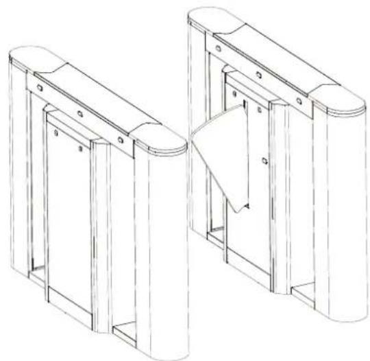
The wing gate is composed of the chassis, core component, wing arms, a PCB (printed circuit board), infrared sensors, a reader, and the access control system.
The system uses standard electric interfaces. It meets fire fighting passage requirements and is equipped with dedicated fire control linkage interfaces. The entire system complies with the same quality standard to ensure reliability, stability, and smoothness of the system during running.
The wing gate is applicable to work attendance, access control, consumption management, and special passage control of enterprises and institutional organizations. It is conducive to the management of ticket check passages in stations, wharves, convention and exhibition centres, and swimming pools.
1.1 Product Appearance and Dimensions
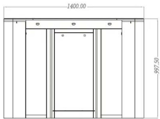
Below is the design and dimensions of FBL6000 Pro:
natural_image
Technical line drawing of two mechanical gate structures with no visible text or symbols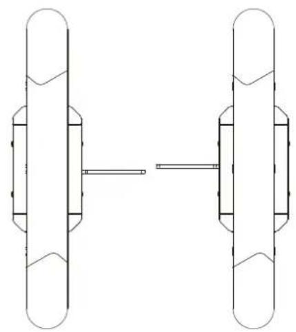
natural_image
Pure mechanical diagram showing two vertical components connected by a horizontal bar, without any text, labels, or symbols.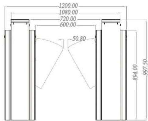
1.2 Technical Parameters
| Dimension (mm) | FBL6000 Pro: L = 1400, W =300, H = 1000 | ||
| Lane width | 600mm | Input voltage | AC110 ~ 240V;50 - 60Hz |
| Input control signal | Switching signal | Output voltage | DC24V |
| Time of opening/closing | 1 second (adjustable) | Relative humidity | 5% - 80% |
| Temperature | -28°C to 60°C | Passage rate | Maximum 30/minute |
| Infrared sensor | 5 | Working environment | Indoor |
1.3 The model number and access control
| Access Model | None | C3-200 and 2*Wiegand reader | inBio 260 and 2* FR1500/ID reader | 2*Facedepot 7B device |
| FBL6000 Pro | √ | |||
| FBL6011 Pro | √ | |||
| FBL6022 Pro | √ | |||
| FBL6033 Pro | √ | |||
| FBL6200 Pro | √ | |||
| FBL6211 Pro | √ | |||
| FBL6222 Pro | √ | |||
| FBL6233 Pro | √ |
Figure 1-1
2. Power-on Test Prior to Installation
Test Procedure:
-
Connect a temporary test cable to the device and supply the input power of AC100-240V adaptive to the device (Note that a ground cable must be connected.)
-
Wait 30 seconds till the wing gate completes the self-test procedure.
-
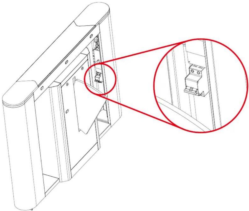
Start the air switch inside the wing gate to check whether the wing gate functions properly and check whether the LED indicators function properly. If they all function properly, start the civil installation. If an exception occurs, contact your sales agent.
natural_image
Technical line drawing of a mechanical assembly with two red circles highlighting a detail (no text or symbols present)Figure 2-1 Air Switch
3. Electric and Civil Installation
1. Device installation conditions
The location where the device is installed must be a concrete flat surface so that the expansion screws can be fastened firmly. If the planned foundation does not meet this criterion, consult professional building or decoration personnel and create stable conditions for firmly fastening of the wing gate.
2. Determination of the location of device installation
Decide the installation location based on the space needed as illustrated in Figure 3-1A and Figure 3-1B.
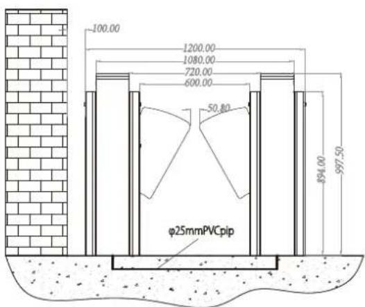
Figure 3-1A Single-Passage Wing Gate
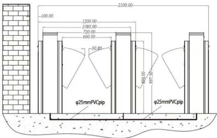
Figure 3-1B Dual-Passage Wing Gate
3. Cable connection
For the location of the hole where the cables come out, please refer to Figure 3-2 below.
4. Device installation
a) Turn on the master machine and slave machine, adjust the wing arms to ensure that the wing arms are in the same line and the distance between wings is 50 ~mm . Turn the wings to the OFF state.
b) Test whether the infrared rays transmitted by infrared sensors on both sides align with each other.
c) Make marks: Mark the screw hole of the base and chassis base edges on the ground.
d) Drill holes: Get ready a hammer drill and a 14 mm drill bit, vertically drill a hole with the depth of 80 mm in the screw hole centre marks.
Alternatively, drill holes according to installation hole positions, see Figure 3-2 for installation hole positions. The unit of the figures in the drawings is mm.
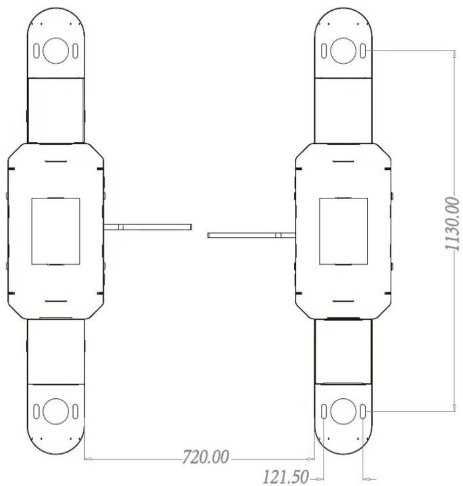
Figure 3-2
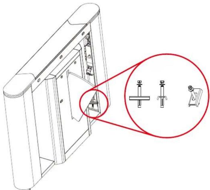
e) Apply screw glue to the outer surface and threads of the expansion screws, insert expansion screws, and put the master machine and slave machine in the marked positions. Use a level to check whether the installation ground foundation is level. If not, use a pad for adjustment.
Note: Eight expansion screws must be completely inserted, as shown in Figure 3-3.
natural_image
Technical line drawing of a mechanical assembly with three labeled components (no text or symbols present)Figure 3-3
5. Card Swiping Warning Lines
It is recommended that a warning line is set to prompt users to swipe cards outside the warning lines, as shown in Figure 3-4.
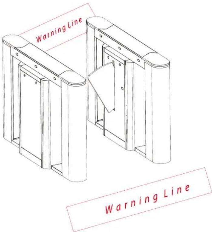
Figure 3-4
4. Menu Operation
- Menu
There are four keys on the control panel, including "UP", "DOWN", "ENT", and "ESC". Press "ENT" to modify settings, press "UP" and "DOWN" button to select a function, and press "ESC" to exit.
● The menu has the following options:
1. Passing mode
Two-way swipe (default)
Left free, Right swipe
Left swipe, Right free
Two-way free
Left prohibit, Right swipe
Left swipe, Right prohibit
Left prohibit, Right free
Left free, Right prohibit
Two-way prohibit
2. Opening speed
Low speed
Medium speed (default)
High speed
3. Closing speed
Low speed
Medium speed (default)
High speed
4. Volume setting
Volume: off
The value ranges from 1 to 16 (default 5).
1 is the minimum value; 16 is the maximum value.
5. Opening duration
After the gate is opened, it will be automatically closed if no one passes through within a certain duration. The default value is 10 seconds. The value ranges from 5 to 60.
6. Reset the counter
Exit counter
Entry counter
All (default)
7. Gate closing delay time
Time: 0\~10s (default 0s)
8. Trailing alarm detection
Mode: Close the door and audio alarm
Audio alarm only (default)
Disable the alarm function
9. Swiping mode
Method: Allow card swiping in the channel (default)
Do not allow card swiping in the channel
10. False direction entry
Mode: Close the door and audio alarm
Audio alarm only (default)
Disable the alarm function
11. Set fire signal
Enable (default)
Disable
12. Exchange voice of door opening
Yes
No (default)
13. Speed compensation of master machine
Compensation value: 000
1\~20 (default: 000)
14. Speed compensation of slave machine
Compensation value: 000
1\~20 (default: 000)
15. Gate closing mode
Out of the anti-pinch area, close the gate. (default)
Out of the channel, close the gate.
16. Memory opening
Whether to open: No (default)
Yes
17. System working mode
Mode: Working mode (default)
Test mode
Restore to factory
18. Version number
Version: V7.0.3
5. Wiring Diagram
Below is the wiring diagram:
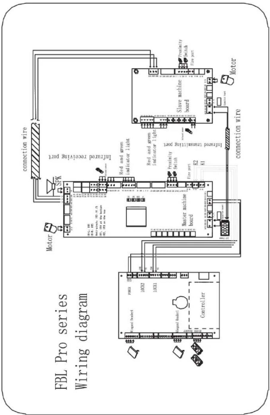
Figure 5-1
6. Product Maintenance
6.1 Chassis
The chassis is made of SAE 304 stainless steel. When the device has been used for a long period, there may be rust or stain on the surface of the chassis. Remember to regularly sand the surface along the grain softly and carefully, then coat the surface with anti-rust oil. Avoid covering the infrared sensors.
6.2 Movement
Cut off the power supply before maintenance. Then, open the door, wipe off the dust on the surface, and lubricate the transmission mechanism. Check and tighten other connection parts.
6.3 Power
Cut off the power supply before maintenance. Check the plug connection; if anything is loose, fix it. Do not randomly change any connection positioning. Check the external power insulation regularly. Do periodic check for any kind of leakage. Check if the technical parameters of each interface are normal. Check the service life of the electronic components.
Caution: The above-mentioned maintenance method of the swing gates, especially the movement and the electric control maintenance, must be carried out by professional personnel. Always remember to cut off the power supply before maintenance and repair.
- Flap Barrier Turnstile-FBL6000 Pro Series
- Contents
- Product Introduction
- Product Appearance and Dimensions
- Technical Parameters
- The model number and access control
- Power-on Test Prior to Installation
- Test Procedure:
- Electric and Civil Installation
- Device installation conditions
- Determination of the location of device installation
- Cable connection
- Device installation
- Card Swiping Warning Lines
- Menu Operation
- - Menu
- ● The menu has the following options:
- Passing mode
- Opening speed
- Closing speed
- Volume setting
- Opening duration
- Reset the counter
- Gate closing delay time
- Trailing alarm detection
- Swiping mode
- False direction entry
- Set fire signal
- Exchange voice of door opening
- Speed compensation of master machine
- Speed compensation of slave machine
- Gate closing mode
- Memory opening
- System working mode
- Version number
- Wiring Diagram
- Product Maintenance
- Chassis
- Movement
- Power
Brand : ZKTeco
Model : FBL1200 PRO
Category : Access Control System