791-44 - Receiver Xantech - Free user manual and instructions
Find the device manual for free 791-44 Xantech in PDF.


| Product Type | IR Receiver |
| Brand | Xantech |
| Model | 791-44 |
| Dimensions (approx.) | 1.5 x 1.0 x 0.5 inches |
| Weight (approx.) | 0.5 oz |
| Power Supply | 12V DC via connection to IR distribution block |
| IR Reception Range | Up to 30 feet (line of sight) |
| Carrier Frequency | 30-60 kHz (compatible with most IR remotes) |
| Connection Type | 3.5mm mono mini plug |
| Compatibility | Xantech IR distribution systems |
| Mounting | Surface mount with included adhesive or screws |
| LED Indicator | Red LED lights when IR signal received |
| Operating Temperature | 32°F to 104°F (0°C to 40°C) |
| Housing Material | ABS plastic |
| Color | Black |
| Maintenance | Wipe with dry cloth |
| Safety | Do not expose to moisture or direct sunlight |
| Spare Parts / Repairability | Not user serviceable; contact Xantech for replacement |
Frequently Asked Questions - 791-44 Xantech
User questions about 791-44 Xantech
0 question about this device. Answer the ones you know or ask your own.
Ask a new question about this device
Download the instructions for your Receiver in PDF format for free! Find your manual 791-44 - Xantech and take your electronic device back in hand. On this page are published all the documents necessary for the use of your device. 791-44 by Xantech.
USER MANUAL 791-44 Xantech
INSTALLATION INSTRUCTIONS
791.44 AMPLIFIED CONNECTING BLOCK
The Model 791-44 is an Amplified Connecting Block that permits up to 10 single or 10 dual emitters (or any combination thereof) to be driven directly at high or low power levels. Up to 100 emitter ports may be driven using 790-00 passive connecting blocks 'daisy chained' from the HIGH IR OUT port. The 791-44 interfaces all Xantech IR Receivers and Keypads to the emitters along with a power supply in an infrared repeater system. It can also serve to provide emitter expansion at the output port of other Xantech devices, such as the 590 Programmable Controller, the 710 Fone Link™ and the 796 Zone Expander. A floating terminal is provided for "STATUS" line connections.
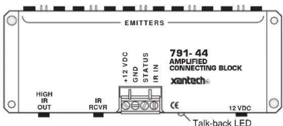
Fig. 1 Model 791-44
SPECIFICATIONS
- 4-screw plug-in terminal for +12VDC, GND, STATUS, & IR IN.
- Quick connect "IR RCVR" input (3.5mm mini stereo jack).
- Red talk-back LED flashes with IR input signal.
- Ten EMITTER output ports, parallel driven (3.5mm mini mono jacks).
- HIGH IR OUT port for emitter expansion (3.5mm mini mono jack). See Fig. 5.
- Use of included jumpers connect either a 100 or a 470-Ohm resistor in series with each emitter jack for high or low power operation.
• 282/283/284/286 series of Emitters may be used in any combination. - Power requirements: 12 volts DC. Uses 781RG or 782-00 Power Supplies (see item 3 below).
• 2.1 mm coaxial power jack. - Dimensions: 6" W x 2-1/4" D x 15/16" H
INSTALLATION
Fig. 2, next page, illustrates a typical installation of a 791-44 in an IR repeater system. A variety of Xantech IR Receivers and a keypad are shown. When configuring a system, please keep the following items in mind:
- More IR receivers may be wired in parallel, in the same manner as shown, up to a maximum of twelve. More than twelve is not recommended because IR noise picked up by the many IR receivers may cause erratic operation and reduce remote control range.
NOTE: This restriction does not apply to Xantech Smart Pads. These may be added virtually without limit, provided power supply requirements are taken into consideration. See item 3.
- Be sure to connect the +12V, Output and Gnd of each IR receiver and keypad to the respective +12VDC, IR IN and GND of the connecting block as shown.
- Power Supply Requirements. You may combine many Xantech keypads, IR receivers, controllers and emitters in a system. Having sufficient power supply voltage and current available is critical for proper operation. Be sure to take the following factors into consideration:
a) The maximum current for proper operation from a 781RG Power Supply is 120 mA (milliamps).
b) The maximum current from a 782-00 Power Supply is 1000 mA.
c) Most IR receivers draw 2 mA without signal and 10 mA with signal (check specs. on actual model).
d) Each 730 Smart Pad draws 7 mA without signal and 65 mA with signal.
e) Each Smart Pad _2 or 3 draws 85 mA with or without signal.
f) Each emitter draws 3 mA in low power mode and 12 mA in high power mode.
g) Add 10 mA for each 794 or 797 Interface module used, if they are powered from the 791-44.
h) When using combinations of these devices, add up the currents as shown in the following example. Then choose the power supply or supplies. Do not exceed their maximum current capabilities as noted above!
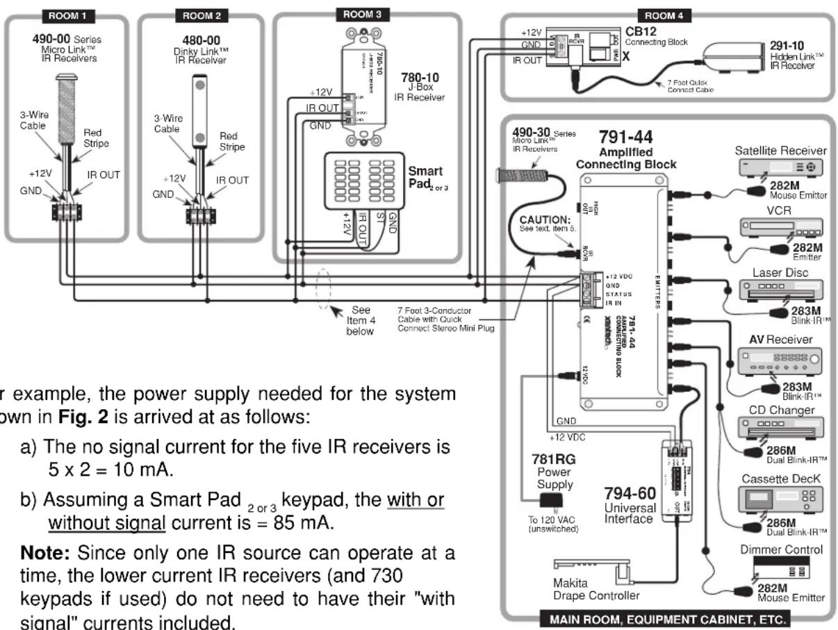
Fig. 2 A typical 791-44 System
d) The current for six emitters is 6 × 3 = 18 mA (in the low power mode. Also the 286 dual emitters count as only one, since they are in series).
e) Now add up all the currents from steps 1 through 4.
10 mA + 85 mA + 10 mA + 18 mA = 123 mA total.
Therefore, in this case, one 781RG power supply can be used.
NOTE: To avoid current "hogging", never connect regulated supplies, such as the 781RG or the 782-00, in parallel!
CAUTION: Do not use unregulated 12V power supply adapters from other manufacturers. These may deliver excessive voltage to the IR receivers and cause them to "latch-up". When this occurs, the "talk-back" LEDs and 283 Blink IR's (if used) will stay on continuously!
- For clarity, connections in this illustration are shown going to a 3-conductor bus in a "daisy chain" fashion. In an actual installation, however, it is recommended that 4-conductor "home-runs" be pulled from each room to the 791-44 Connecting Block in the main room. This maintains higher power supply voltage to each IR receiver and keypad for best operation (plus a spare lead).
- The "IR RCVR" jack on the 791-44 allows the 490-30 (and other Xantech IR Receivers outfitted with a 3.5 mm stereo mini plug) to be plugged directly into the 791-44. You can do this when the 791-44 Connecting Block is within reach of the IR receiver's cable -- such as when installing the 490-30 in a cabinet where the controlled equipment is behind closed doors.
CAUTION: Plug only Xantech IR Receivers equip-ped with a stereo mini plug into the IR RCVR jack. Do not plug in emitters or other devices. To do so will destroy emitters and damage power supplies!
CAUTION For Shielded Wire and Long Lead Lengths
When using long lengths (>50 feet) of inter-room shielded cable, it may be necessary to connect a 470 Ohm 1/8 Watt resistor between IR IN (signal) and GND at the 4-screw terminals of the 791-44. Refer to Fig. 3.
The resistor discharges the cable capacitance more quickly, allowing IR codes of high bit rates to pass without data loss for consistent command executions.
Emitter Output Ports - High and Low Power Settings
The emitter ports are driven in parallel with a choice of either a 100 Ohm or a 470 Ohm resistor connected in series with each port. The 100 Ohm choice delivers high power output and the 470 Ohm setting is lower power. The high power setting is achieved by plugging a small jumper (10 are supplied) onto the pair of pins adjacent to the desired emitter port, as shown in Fig. 4 below. The low power option is with the jumper removed.
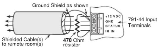
Fig. 3 Using a 470 Ohm Capacitance Discharge Resistor
NOTE: The 791-44's are shipped from the factory with the jumpers removed (low power position).
Consider the following factors when choosing high or low power modes:
- In the majority of cases, when you mount an emitter on the IR sensor window of the controlled device, you would use the low power mode (jumpers removed). This prevents overload of high gain sensor circuits and allows proper operation.
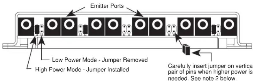
- The high power mode may be used in installations where you mount the emitters on an adjacent cabinet wall or door a short distance from the unit's sensor. Another instance is when you place an emitter inside the device, but cannot place it close to the IR sensor. In such cases, you may need the extra power of the high power mode to blast through printed circuit boards or around chassis structures. In addition, when using the lower output 283 and 286 Blink IR's, you may need the high power mode for some devices that have less sensitive IR sensors.
- The resistors also provide current sharing to each emitter and allow the use of dual emitters in combination with single emitters. You may, therefore, connect any combination of the 282, 283, 284, & 286 series of emitters in the same system, such as that illustrated in Fig. 2, to drive the desired number of devices.
When using less than 10 of the emitter ports, you may plug into any of them without regard to order.
Emitter Expansion
If more than 10 emitter ports are needed, you may daisy chain from the HIGH IR OUT port on the 791-44 to the IN/OUT port on a model 790 passive connecting block as follows:
You may daisy chain up to a maximum of 9 model 790's for 100 emitter ports total as shown in Fig. 5. Be sure to use an adequate power supply. CAUTION: Never plug emitters directly into the HIGH IR OUT or HIGH IN/OUTports. To do so will destroy the emitters!
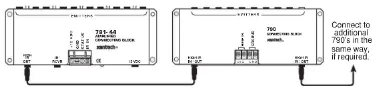
Fig. 5 Emitter Expansion
Using The "STATUS" Terminal on the 791-44
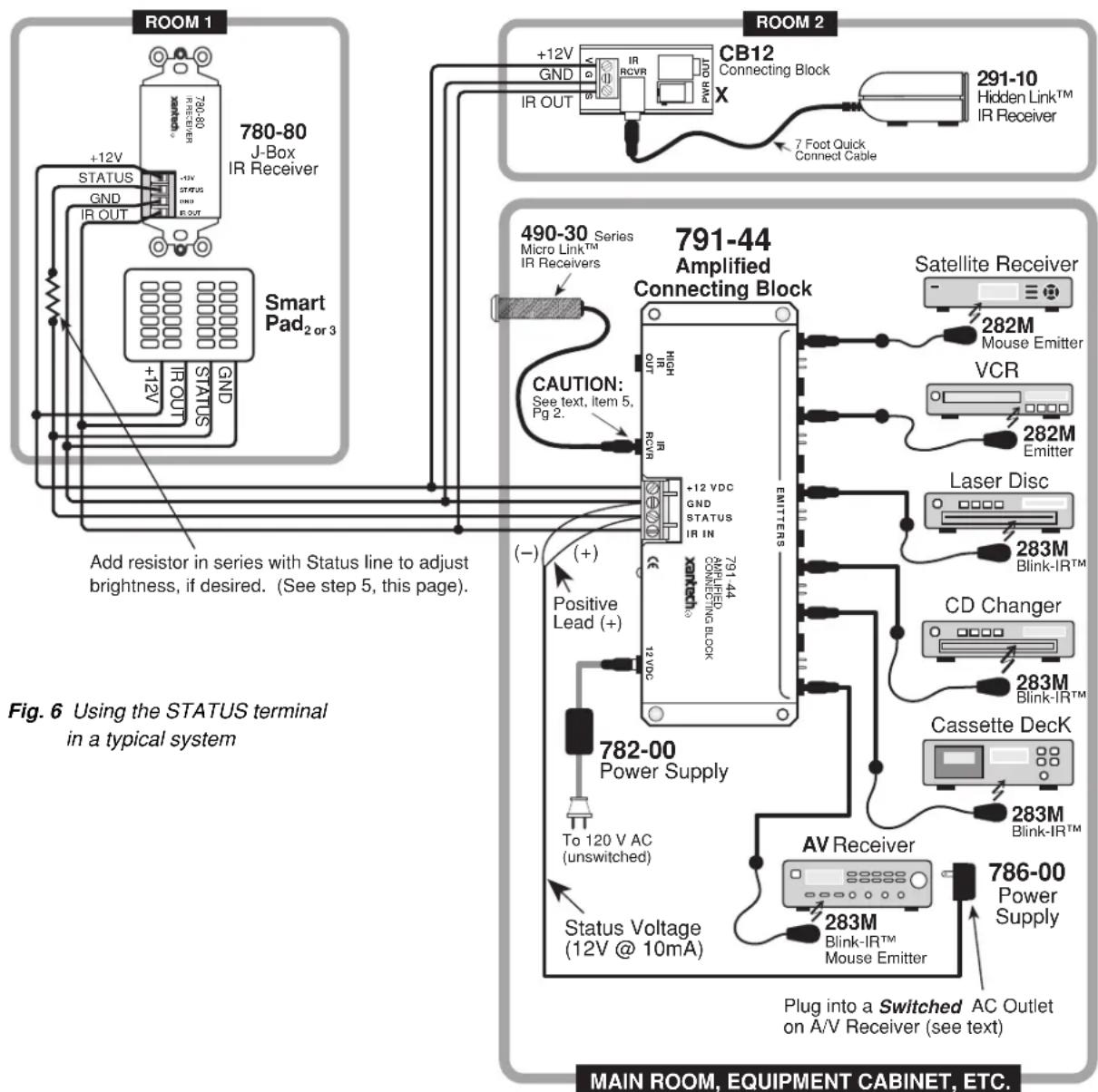
Fig. 6 illustrates a single zone system where the Status indicator on a Xantech 780-80 IR Receiver and on a Smart Pad _2 or 3 in a remote room, shows the ON/OFF status of an A/V receiver.
The STATUS and GND terminals on the 791-44 provide convenient tie points for the voltage that drives STATUS indicators on certain Xantech products (such as the 780-80 IR Receiver & Smart Pad _2 or 3).
To connect such a system, proceed as follows:
- Unplug all power plugs for the A/V system.
- Plug a 12V adapter, such as the Xantech 786-00 Power Supply, into a switched AC Outlet on the back of the A/V receiver (or integrated amplifier, preamp, etc.).
- Cut the attached plug off the 12V adapter and connect the two leads to the STATUS and GND terminals on the 791-44 (+" to STATUS, "-" to GND).
- Connect the 4-conductor inter-room cable between the 791-44, the Smart Pad _2 or 3 and the 780-80 as shown in Fig.6.
- If you wish to adjust the brightness of the Status LED on the 780-80, place a resistor in series with the STATUS lead as shown in Fig. 6. Use a value that achieves the desired brightness level (usually 1k Ohm to 10k Ohm, 1/8 watt).
NOTE: The brightness of the STATUS LEDs (bank indicators) on the Smart Pad _2 or 3 cannot be adjusted! Do not use a resistor in series with them!
MOUNTING
The 791-44 can be conveniently mounted to a wall or shelf by using the two sheet-metal screws supplied. You may also apply the 4 self adhesive rubber feet (supplied) if you wish to place the unit on a finished surface. The unit may be mounted in any orientation to accommodate the installation.
Brand : Xantech
Model : 791-44
Category : Receiver