HL95K - Receiver Xantech - Free user manual and instructions
Find the device manual for free HL95K Xantech in PDF.


| Product Type | Infrared Repeater Receiver |
| Brand | Xantech |
| Model | HL95K |
| Dimensions | 2.00" x 3.15" x 0.70" (51mm x 80mm x 18mm) |
| Power Supply | Included 781ERGPS, 12VDC, 200mA |
| Receiver Power Requirements | +12VDC, 20mA |
| Reception Range | Up to 80 feet (depending on remote output and ambient conditions) |
| Reception Angle | 55 degrees off axis |
| Carrier Frequency Bandwidth | 25 - 60 kHz |
| Maximum Transmission Length | 1 mile using 18 gauge wire |
| Maximum Current Output | 100mA |
| Included Items | HL Series IR Receiver, 789-44 Connecting Block, 4x 283D Designer Emitters, 781ERGPS Power Supply |
| Cable | 7-foot with 3.5mm stereo mini plug |
| Connector Wiring | Tip: Signal, Ring: Ground, Sleeve: +12VDC |
| Compatibility | Xantech connecting blocks (789-44, CB12, CB60, 791-44) |
| Special Features | Plasma/LCD/LED/CFL friendly, red talk-back LED, color-coded connectors |
| Installation Method | Quick-start plug-and-play with connecting block |
| Remote Room Capability | Up to 12 receivers using CB12 connecting block |
| Warranty | Limited Lifetime |
| Maintenance | Wipe with a dry cloth |
| Safety | Use only with provided power supply |
| Spare Parts | 283D emitters, connecting blocks available |
| Repairability | Contact Xantech support for service |
Frequently Asked Questions - HL95K Xantech
User questions about HL95K Xantech
0 question about this device. Answer the ones you know or ask your own.
Ask a new question about this device
Download the instructions for your Receiver in PDF format for free! Find your manual HL95K - Xantech and take your electronic device back in hand. On this page are published all the documents necessary for the use of your device. HL95K by Xantech.
USER MANUAL HL95K Xantech
Hidden Link™ Shelf Top Extended Range
Plasma\LCD\LED\CFL Friendly IR Receiver
xantech
DESCRIPTION
The Hidden Link IR Receiver is a small shelf-top infrared repeater assembly. It includes an IR receiver. a 789-44 Connecting Block, a Power supply, and 4 283D emitters. The Hidden Link IR Receiver is equipped with a 7-foot cable and a 3.5mm stereo mini plug, which is plugged directly into the "IR RCVR" jack on the 789-44. It can also be plugged into the "AUX" or "IR RCVR" jack of other Xantech connecting blocks, such as the models CB12, CB60, and 791-44. The Hidden Link IR Receiver is primarily intended for use in installations where the connecting block is within reach of its 7-foot cable – as when installing the Hidden Link IR Receiver in a cabinet where the controlled equipment is behind closed doors.
FEATURES
- Very small package, only 2.00"L x 3.15"W x 0.70"H.
• System testing red-talk-back LED. - Includes 789-44 Connecting Block, Power supply, and four 283D emitters for easy system installation.
SPECIFICATIONS
- Infrared carrier frequency bandwidth: 25 – 60 kHz.
- Reception range: Up to 80 feet, depending on remote control output strength and ambient conditions.
• Nominal reception angle: 55 degrees off axis. - Cable requirements: See "INSTALLATION" below.
• Max. transmission length: 1 mile using 18 gauge wire.
• Maximum current output: 100mA - Drives IR emitters through Xantech Connecting Blocks, Controllers, etc.
- Dimensions: 2.00"x3.15"x0.70" (51mm x 80mm x 18mm)
• Power requirements: +12VDC, 20mA.
INSTALLATION
QUICK-START
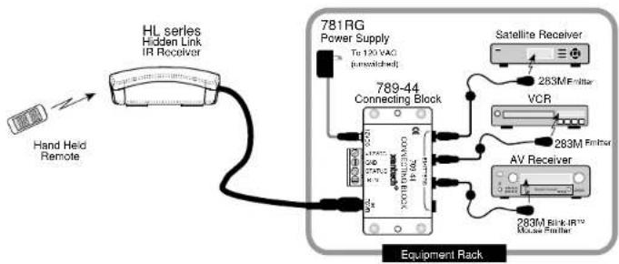
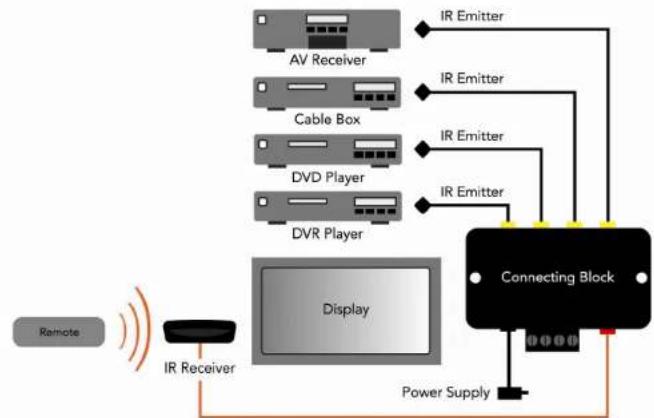
A typical system will use an IR receiver, several emitters, and a power supply all connected to a connecting block.
- Connect the IR receiver to the "IR RCVR" port on the connecting block. The 'red' connector is installed to the 'red' plug. Note: In some extended distances, additional 3-conductor may be required and can be connected to the terminals on the connecting block.
- Connect the Emitters to the connecting block. The 'yellow' connector is installed to the 'yellow' plug.
- Connect the power supply to the connecting block.
- Installation complete
In this system a 286D Dual Blink-IR Designer Emitter is shown connected to the "OUT" jack of the 789-44. A single emitter could also be used, such as the model 282D or 283D. If expansion beyond four emitters is required, use a Xantech 791-44 Connecting Block in place of the 789-44.
CABLE CONNECTIONS
The HL series may also be used where the 7-foot cable is not long enough. Simply cut off the mini plug, strip the leads and splice them to a 3-conductor extension cable with a terminal block or other means. Then connect the extension cable to the 3-terminal block on a CB12 or a 789-44 as shown in the figure below.
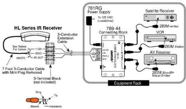
| 3.5mm mini plug Signal Name | Wire Color | |
| TIP SIGNAL WHITE | ||
| RING GROUND BLACK | ||
| SLEEVE +12VDC RED | ||
The 3-conductor inter-room cable (24 gauge up to 200', 22 gauge up to 600', 20 gauge up to 2000', 18 gauge up to 5000'), is run to the main room.
While it is possible to make wired connections without the connecting block, it is not recommended. The connecting block reduces installation time, helps to eliminate errors, allows easy troubleshooting and permits easy system upgrades later, if needed.
REMOTE ROOM APPLICATION
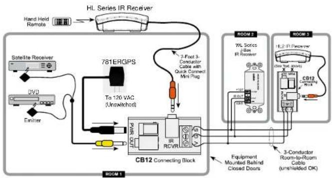
The optional CB12 Connecting Block has a three terminal input strip for connection of external infrared receivers should you wish to control your equipment from other rooms.
- The terminals are marked V G S. (V = +12V, G = Ground, and S = IR Signal).
- Make connections as shown in the figure below. Run a 3-conductor cable (24 to 18 gauge wire, stranded or solid) from each remote room to the VGS terminals of the CB12.
- When you use a Hidden Link IR Receiver in a remote room, do not plug in a power supply or use the "OUT" jack in the CB12, as shown in the figure below.
- You may use more IR receivers, connected in the same manner, up to a maximum of 12.
flowchart
graph TD
    A["Hand Hold Remote"] --> B["HL Series IR Receiver"]
    B --> C["7-Port 3-Conductor Cable with Quick Connect Mini Plug"]
    C --> D["To 120 VAC (Unswitched)"]
    D --> E["CB12 Connecting Block"]
    E --> F["Room 1"]
    E --> G["Room 2"]
    E --> H["Room 3"]
    E --> I["Equipment Mounted Behind Closed Doors"]
    I --> J["3-Conductor Room-to-Room Cable (unshielded OK)"]
    J --> K["7-Port 3-Conductor Cable with Quick Connect Mini Plug"]
    K --> L["7-Port 3-Conductor Cable with Quick Connect Mini Plug"]
    L --> M["7-Port 3-Conductor Cable with Quick Connect Mini Plug"]
    M --> N["7-Port 3-Conductor Cable with Quick Connect Mini Plug"]
    N --> O["7-Port 3-Conductor Cable with Quick Connect Mini Plug"]
    O --> P["7-Port 3-Conductor Cable with Quick Connect Mini Plug"]
    P --> Q["7-Port 3-Conductor Cable with Quick Connect Mini Plug"]
    Q --> R["7-Port 3-Conductor Cable with Quick Connect Mini Plug"]
    R --> S["7-Port 3-Conductor Cable with Quick Connect Mini Plug"]
    S --> T["7-Port 3-Conductor Cable with Quick Connect Mini Plug"]
    T --> U["7-Port 3-Conductor Cable with Quick Connect Mini Plug"]
    U --> V["7-Port 3-Conductor Cable with Quick Connect Mini Plug"]
    V --> W["7-Port 3-Conductor Cable with Quick Connect Mini Plug"]
    W --> X["7-Port 3-Conductor Cable with Quick Connect Mini Plug"]
    X --> Y["7-Port 3-Conductor Cable with Quick Connect Mini Plug"]
    Y --> Z["7-Port 3-Conductor Cable with Quick Connect Mini Plug"]
    Z --> AA["7-Port 3-Conductor Cable with Quick Connect Mini Plug"]
    AA --> AB["7-Port 3-Conductor Cable with Quick Connect Mini Plug"]
    AB --> AC["7-Port 3-Conductor Cable with Quick Connect Mini Plug"]
    AC --> AD["7-Port 3-Conductor Cable with Quick Connect Mini Plug"]
    AD --> AE["7-Port 3-Conductor Cable with Quick Connect Mini Plug"]
    AE --> AF["7-Port 3-Conductor Cable with Quick Connect Mini Plug"]
    AF --> AG["7-Port 3-Conductor Cable with Quick Connect Mini Plug"]
    AG --> AH["7-Port 3-Conductor Cable with Quick Connect Mini Plug"]
    AH --> AI["7-Port 3-Conductor Cable with Quick Connect Mini Plug"]
    AI --> AJ["7-Port 3-Conductor Cable with Quick Connect Mini Plug"]
    AJ --> AK["7-Port 3-Conductor Cable with Quick Connect Mini Plug"]
    AK --> AL["7-Port 3-Conductor Cable with Quick Connect Mini Plug"]
    AL --> AM["7-Port 3-Conductor Cable with Quick Connect Mini Plug"]
    AM --> AN["7-Port 3-Conductor Cable with Quick Connect Mini Plug"]
    AN --> AO["7-Port 3-Conductor Cable with Quick Connect Mini Plug"]
    AO --> AP["7-Port 3-Conductor Cable with Quick Connect Mini Plug"]
    AP --> AQ["7-Port 3-Conductor Cable with Quick Connect Mini Plug"]
    AQ --> AR["7-Port 3-Conductor Cable with Quick Connect Mini Plug"]
    AR --> AS["7-Port 3-Conductor Cable with Quick Connect Mini Plug"]
    AS --> AT["7-Port 3-Conductor Cable with Quick Connect Mini Plug"]
    AT --> AU["7-Port 3-Conductor Cable with Quick Connect Mini Plug"]
    AU --> AV["7-Port 3-Conductor Cable with Quick Connect Mini Plug"]
    AV --> AW["7-Port 3-Conductor Cable with Quick Connect Mini Plug"]
    AW --> AX["7-Port 3-Conductor Cable with Quick Connect Mini Plug"]
    AX --> AY["7-Port 3-Conductor Cable with Quick Connect Mini Plug"]
    AY --> AZ["7-Port 3-Conductor Cable with Quick Connect Mini Plug"]
    AZ --> BA["7-Port 3-Conductor Cable with Quick Connect Mini Plug"]
    BA --> BB["7-Port 3-Conductor Cable with Quick Connect Mini Plug"]
    BB --> BC["7-Port 3-Conductor Cable with Quick Connect Mini Plug"]
    BC --> BD["7-Port 3-Conductor Cable with Quick Connect Mini Plug"]
    BD --> BE["7-Port 3-Conductor Cable with Quick Connect Mini Plug"]
    BE --> BF["7-Port 3-Conductor Cable with Quick Connect Mini Plug"]
    BF --> BG["7-Port 3-Conductor Cable with Quick Connect Mini Plug"]
    BG --> BH["7-Port 3-Conductor Cable with Quick Connect Mini Plug"]
    BH --> BI["7-Port 3-Conductor Cable with Quick Connect Mini Plug"]
    BI --> BJ["7-Port 3-Conductor Cable with Quick Connect Mini Plug"]
    BJ --> BK["7-Port 3-Conductor Cable with Quick Connect Mini Plug"]
    BK --> BL["7-Port 3-Conductor Cable with Quick Connect Mini Plug"]
    BL --> BM["7-Port 3-Conductor Cable with Quick Connect Mini Plug"]
    BM --> BN["7-Port 3-Conductor Cable with Quick Connect Mini Plug"]
    BN --> BO["7-Port 3-Conductor Cable with Quick Connect Mini Plug"]
    BO --> BP["7-Port 3-Conductor Cable with Quick Connect Mini Plug"]
    BP --> BQ["7-Port 3-Conductor Cable with Quick Connect Mini Plug"]
    BQ --> BR["7-Port 3-Conductor Cable with Quick Connect Mini Plug"]
    BR --> BS["7-Port 3-Conductor Cable with Quick Connect Mini Plug"]
    BS --> BT["7-Port 3-Conductor Cable with Quick Connect Mini Plug"]
    BT --> BU["7-Port 3-Conductor Cable with Quick Connect Mini Plug"]
    BU --> BV["7-Port 3-Conductor Cable with Quick Connect Mini Plug"]
    BV --> BW["7-Port 3-Conductor Cable with Quick Connect Mini Plug"]
    BW --> BX["7-Port 3-Conductor Cable with Quick Connect Mini Plug"]
    BX --> BY["7-Port 3-Conductor Cable with Quick Connect Mini Plug"]
    BY --> BZ["7-Port 3-Conductor Cable with Quick Connect Mini Plug"]
    BZ --> CA["7-Port 3-Conductor Cable with Quick Connect Mini Plug"]
    CA --> CB["7-Port 3-Conductor Cable with Quick Connect Mini Plug"]
    CB --> CC["7-Port 3-Conductor Cable with Quick Connect Mini Plug"]
    CC --> CD["7-Port 3-Conductor Cable with Quick Connect Mini Plug"]
    CD --> CE["7-Port 3-Conductor Cable with Quick Connect Mini Plug"]
    CE --> CF["7-Port 3-Conductor Cable with Quick Connect Mini Plug"]
    CF --> CG["7-Port 3-Conductor Cable with Quick Connect Mini Plug"]
    CG --> CH["7-Port 3-Conductor Cable with Quick Connect Mini Plug"]
    CH --> CI["7-Port 3-Conductor Cable with Quick Connect Mini Plug"]
    CI --> CJ["7-Port 3-Conductor Cable with Quick Connect Mini Plug"]
    CJ --> CK["7-Port 3-Conductor Cable with Quick Connect Mini Plug"]
    CK --> CL["7-Port 3-Conductor Cable with Quick Connect Mini Plug"]
    CL --> CM["7-Port 3-Conductor Cable with Quick Connect Mini Plug"]
    CM --> CN["7-Port 3-Conductor Cable with Quick Connect Mini Plug"]
    CN --> CO["7-Port 3-Conductor Cable with Quick Connect Mini Plug"]
    CO --> CP["7-Port 3-Conductor Cable with Quick Connect Mini Plug"]
    CP --> CQ["7-Port 3-Conductor Cable with Quick Connect Mini Plug"]
    CQ --> CR["7-Port 3-Conductor Cable with Quick Connect Mini Plug"]
    CR --> CS["7-Port 3-Conductor Cable with Quick Connect Mini Plug"]
    CS --> CT["7-Port 3-Conductor Cable with Quick Connect Mini Plug"]
    CT --> CU["7-Port 3-Conductor Cable with Quick Connect Mini Plug"]
    CU --> CV["7-Port 3-Conductor Cable with Quick Connect Mini Plug"]
    CV --> CW["7-Port 3-Conductor Cable with Quick Connect Mini Plug"]
    CW --> CX["7-Port 3-Conductor Cable with Quick Connect Mini Plug"]
    CX --> CY["7-Port 3-Conductor Cable with Quick Connect Mini Plug"]
    CY --> CZ["7-Port 3-Conductor Cable with Quick Connect Mini Plug"]
    CZ --> DA["7-Port 3-Conductor Cable with Quick Connect Mini Plug"]
    DA --> DB["7-Port 3-Conductor Cable with Quick Connect Mini Plug"]
    DB --> DC["7-Port 3-Conductor Cable with Quick Connect Mini Plug"]
    DC --> DD["7-Port 3-Conductor Cable with Quick Connect Mini Plug"]
    DD --> DE["7-Port 3-Conductor Cable with Quick Connect Mini Plug"]
    DE --> DF["7-Port 3-Conductor Cable with Quick Connect Mini Plug"]
    DF --> DG["7-Port 3-Conductor Cable with Quick Connect Mini Plug"]
    DG --> DH["7-Port 3-Conductor Cable with Quick Connect Mini Plug"]
    DH --> DI["7-Port 3-Conductor Cable with Quick Connect Mini Plug"]
    DI --> DJ["7-Port 3-Conductor Cable with Quick Connect Mini Plug"]
    DJ --> DK["7-Port 3-Conductor Cable with Quick Connect Mini Plug"]
    DK --> DL["7-Port 3-Conductor Cable with Quick Connect Mini Plug"]
    DL --> DM["7-Port 3-Conductor Cable with Quick Connect Mini Plug"]
    DM --> DN["7-Port 3-Conductor Cable with Quick Connect Mini Plug"]
    DN --> DO
PLACEMENT
The IR receiver should be located so that it is not directly facing a light source such as lamps or displays (standard, LCD, and Plasma). When mounted near a display, it should be flush to the display and away from light reflections that may occur.
1.
Hidden-Link (HL) IR Receiver Kit
DESCRIPTION
The HL Series Kit comes with everything needed for a complete IR repeater system. With a Xantech IR Kit, equipment can now be concealed for clean room design. In addition, a centralized IR receiver means there is only one IR target resulting in improved remote control interaction. Featuring color-coded connectors, a Xantech IR Kit is now an easy to install, and allows a worry-free installation.
INCLUDED ITEMS
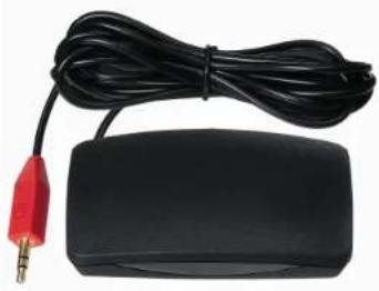
ITEM A: (1) HL Series IR Receiver
natural_image
Black electronic device with red and black connectors, connected by a black cable (no visible text or symbols)ITEM B: (1) 789-44 Connecting Block
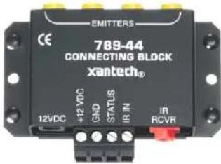
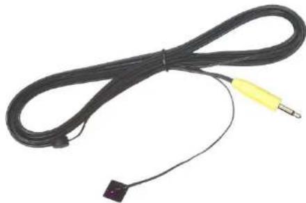
ITEM C: (4) 283D Designer Emitters
natural_image
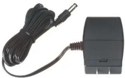
Coiled black cable with a yellow and black connector, no visible text or symbolsITEM D: (1) 781ERGPS Power Supply
natural_image
Black electronic device with coiled cable and connector (no visible text or symbols)1
STEP 1:
Plug in the 2.1mm Coaxial power plug of the 781ERGPS Power Supply (ITEM D) into the jack labeled 12VDC on the 789-44 Connecting Block (ITEM B).
Plug the AC end of the 781ERGPS Power Supply (ITEM D) into a 'un-switched' 120V AC Line outlet.
STEP 2:
Connect the 3.5mm stereo mini plug from the 481D IR Receiver (ITEM A) to the 'IR RCVR' input located on the 789-44 Connecting Block (ITEM B).
The RED connector connects to the RED receptacle.
STEP 3:
Plug in the 283D Designer Emitters 3.5mm mono mini plug (ITEM C) into the jacks labeled EMITTERS on the 789-44 (ITEM B) and affix the opposite end to the IR Sensor Window of the controlled equipment. Extra double sided adhesive tape is included.
The YELLOW connector connects to the YELLOW receptacle.
flowchart
graph TD
    A["Remote"] --> B["IR Receiver"]
    B --> C["Display"]
    C --> D["Connecting Block"]
    D --> E["Power Supply"]
    E --> F["AR"]
    F --> G["AV Receiver"]
    F --> H["Cable Box"]
    F --> I["DVD Player"]
    F --> J["DVR Player"]
    G --> K["IR Emitter"]
    H --> L["IR Emitter"]
    I --> M["IR Emitter"]
    J --> N["IR Emitter"]
IR Troubleshooting Guide
NOTE: Due to the many variables in a given installation, the troubleshooting countermeasures you will have to take may vary from job to job. Each installation is different due to the number of IR receivers in use, length of wire runs, type of wire, amount of ambient IR noise present, etc.... Therefore, your countermeasures for a particular job will range from nothing at all, to any combination of the solutions listed below.
IR Receivers: Model #'s DL, HL, ML, and WL series
Symptom #1: DIM or NO Talk Back LED during IR Reception or reduced operational range
| Cause: Solution | ||
| 1. | Weak Batteries in Transmitting Remote. | Replace batteries. |
| 2. | Bad Emitter or no emitter plugged into connecting block. | Test emitter and verify wiring. |
| 3. | Signal wire between IR Receiver and the Connecting Block is open. | Recheck wiring. |
| 4. | Power Supply not putting out proper voltage. | Verify supply is a 12VDC regulated supply reading between 11.5 to 13VDC under load. Should be using Power Supply Model 781ERGPS (12VDC Regulated, 200mA) or 782ERGPS (12VDC Regulated, 1.2A) |
| 5. | Output from the IR receiver/connecting block is connected to a high impedance IR input jack on a component. | If you are using a passive connecting block, such as a 789-44, and the system is not working, try the amplified connecting block, model 791-44. Put one of the small plastic case jumpers supplied with the block on the pins next to the emitter jack. This will provide the IR-in jack on the component with a hotter signal. |
| 6. | IR Receiver is inoperable. | Replace Receiver. |
| 7. | (XTRALINK Only) RF Amplifier is being used on same COAX Line anywhere between the Coupler (CPL94) and Injector (INJ94). | Need to use a Bypass Kit (model BYPASS94 Kit) to route the IR control signals around the amplifier(s). |
Symptom #2: TB LED on IR Receiver (and/or Emitters) Dimly lit or flickering
| Cause: Solution | ||
| 1. | Signal and ground wires are reversed or shorted either at the connecting block or IR receiver. | Recheck your wiring. |
| 2. | Defective emitter. | Replace Emitter |
| 3. | Relatively high levels of ambient noise. This can be due to any of the following: Sunlight, fluorescent Lighting or Plasma Displays. | In this case use either a SUN filter (SUNKIT), or any of our 'Plasma/CFL Friendly' IR Receivers (DL85/95, HL85/95, ML85/95, WL85/95). These can also be used in direct sunlight and in the presence of 'tube style' fluorescent lighting. |
| 4. | EMI induced noise. This can be due to light dimmer controls or other radiating electronic devices (PC's or any poorly shielded electronic device). | Reposition IR Receiver and/or cabling away from emitting device. You can also place a 470Ohm resistor in parallel with the IR Signal and GND connections on the connecting block. This will also help alleviate any stray capacitance in the cable. |
| 5. | Plasma Interference | Use an 85 or 95 series Plasma 'Friendly' IR Receiver. If already using a 85 or 95 unit, please note the Plasma interference can be reflected off of any item it comes into contact with within approx. 3ft. From the front of the display. Keeping this in mind, make sure that the IR receiver is free from any obstruction that might reflect back into the receiving eye. |
Symptom #3: TB LED on IR Receiver (and/or Emitters) on solid
| Cause: Solution | ||
| 1. | Plasma Interference | Use a 85 or 95 series Plasma 'Friendly' Receiver. If already using a this unit, please note the Plasma interference can be reflected off of any item it comes into contact with within approx. 3ft. From the front of the display. Keeping this in mind, make sure that the IR receiver is free from any obstruction that might reflect back into the receiving eye. |
| 2. | Voltage and Ground wires are reversed at the connecting block or IR Receiver | Recheck your wiring. |
| 3. | Relatively high levels of ambient noise. This can be due to any of the following: Sunlight, fluorescent Lighting or Plasma Displays. | In this case use either a SUN filter (SUNKIT), or any of our 'Plasma/CFL Friendly' IR Recivers (DL85/95, HL85/95, ML85/95, WL85/95). These can also be used in direct sunlight and in the presence of 'tube style' fluorescent lighting. |
| 4. | EMI induced noise. This can be due to light dimmer controls or other radiating electronic devices (PC's or any poorly shielded electronic device). | Reposition IR Receiver and/or cabling away from emitting device. You can also place a 470Ohm resistor in parallel with the IR Signal and GND connections on the connecting block. This will also help alleviate any stray capacitance in the cable. |
| 5. | Power Supply not putting out proper voltage. | Verify supply is a 12VDC regulated supply reading between 11.5 to 13VDC under load. |
Symptom #4: TB LED on IR Rec. blinks but 283D or 286D 'Blink' style Emitters do not
| Cause: Solution | ||
| 1. | There may be a short, such as a staple driven through the Signal and GND wires of the IR Receiver and/or the emitter. | Recheck your wiring. |
| 2. | Emitter may be shorted internally | Replace Emitter or use TEST EMITTER to check circuit. |
| 3 | (XTRALINK Only) TV on same splitter with no IR Receiver installed | Place a DC Blocker (Model 203-00) on any TV Leg without IR Receiver |
Symptom #5: Intermittent IR control (i.e. buttons on remote need to be pressed multiple times)
| Cause: Solution | ||
| 1. | Plasma Interference | Use a 85 or 95 series Plasma 'Friendly' Receiver |
| 2. | Relatively high levels of ambient noise. This can be due to any of the following: Sunlight, fluorescent Lighting or Plasma Displays. | In this case use either a SUN filter (SUNKIT), or any of our 'Plasma/CFL Friendly' IR Receivers (DL85/95, HL85/95, ML85/95, WL85/95). These can also be used in direct sunlight and in the presence of 'tube style' fluorescent lighting. |
| 3. | Long Wire Runs - shielded wire typically of 100 feet (30 meters) or longer causes a filter effect due to accumulated capacitance of the wire. Intermittent, or no IR control, could actually be because of the longer wire runs. | Putting a 470-ohm resistor in parallel at the connecting block between signal and ground will effectively discharge the capacitance of the wire. This will allow the signal to travel farther on shielded wire. Adding a resistor between the input and ground of the connecting block will drop the IR level down somewhat. Passive connecting blocks, such as the 789-44, may not have enough signal output for consistent control of the equipment. You may have to upgrade to an amplified connecting block to bring the IR level back to normal. In these cases, the 791-44 would be an ideal connecting block for single zone systems while the 795-20 would work best for a 2-4 zone system. |
Symptom 6: Emitters function but some (or all) components do not respond.
| Cause: Solution | ||
| 1. | Emitter placement is incorrect. | Reposition the Emitter so that it is directly over the components sensor window.Consult the components owners' manual of the unit for the exact location of the IR Sensor Window. |
| 2. | Emitter placement is correct but the signal is overpowering the unit or there is bleed-through from other emitters close by. | Reposition the Emitter to a position that is suitable for the unit. Use a 283 or 286D Blink style emitter (they have a lower output than non-blink emitters 282 and 284M). If the components do not need to be controlled directly without an IR Repeater system (components are located in an equipment closet), place a Mouse Emitter Shield cover over the Emitter (PN#MS1). The rounded (non-stick) side of the emitter is a hi-output side and can reflect off other devices and overpower some components IR Sensors. If using a CB12 connecting block, try a 789-44 connecting block. This has a series resistor at the output, which will limit current to the Emitter. |
Symptom #7: Absolutely No Functionality (How to determine which component is at fault)
| Component to Test Instructions | ||
| 1. | Verify Power Supply | With a Multimeter, measure the DC Voltage of the supply while it is connected to the Connecting Block. Put the Negative lead of the meter on the terminal marked GND and the Positive Lead on the terminal marked 12VDC (or V). You should get a reading between 11.5VDC and 13.0VDC. If not, remove the supply from the Connecting block and measure again this time directly on the 2.5mm Coaxial plug. If it reads between 11.5VDC and 13VDC, power supply is most likely good. Reconnect to the Connecting Block and proceed to step 2. NOTE: In most cases this will indicate the supply is good but in some cases the supply can still be bad (i.e. reads good when not plugged in but may not be able to handle the current load of the system.) |
| 2. | Verify Emitter. (283D or 286D Blink Style ONLY) | Remove the power supply from the connecting block and all Emitters from the output. Place a jumper wire on the connecting block between IR and +12v. Reconnect the Power Supply and one emitter. The Emitter should Light bright and solid. Repeat for all emitters. |
| 3. | Verify Emitter. (282M or 284M NON Blink Style) | Use a diode tester to verify proper Emitter operation. Remove Emitter from Connecting Block. Place the Positive Lead of the tester on the TIP of the Mono Mini Plug and the Negative Lead on the Shield of the Mono Mini Plug. Meter should read a voltage. When the leads are reversed (Positive lead on Shield and Negative lead on TIP) you should not get any voltage reading at all. |
| 4. | Verify IR Receiver. | Remove the power supply from the connecting block and all Emitters from the output. Place a jumper wire on the connecting block between IR Signal and GND. Reconnect the Power Supply. With a known good hand-held remote, shoot a constant IR Command at the receiver and verify the TB LED on the Receiver lights. |
xantech
Limited Warranty
Xantech® warrants its products to be free of defects in materials or workmanship. This is a Limited Lifetime warranty from the date of purchase by the original consumer. Any products returned to Xantech and found to be defective by Xantech within the warranty period will be repaired or replaced, at Xantech's option, at no charge. Xantech will not be responsible for the actual cost of installation or removal of the product, nor for any incidental or consequential damages. Some states do not allow the exclusion or limitation of incidental or consequential damages, so the above limitation may not apply to you. This warranty gives you specific legal rights. You may have additional legal rights that vary from state to state.
Xantech Corporation
13100 Telfair Ave., Sylmar CA 91342 | Xantech.com
Installation Instructions, HL95K © 2009 Xantech Corporation Document # 08905317A
This document is copyright protected. No part of this manual may be copied or reproduced in any form without prior written consent from Xantech Corporation. Xantech Corporation shall not be liable for operational, technical, or editorial errors/omissions made in this document.
Brand : Xantech
Model : HL95K
Category : Receiver