
710105 - Uncategorized CaterChef - Free user manual and instructions
Find the device manual for free 710105 CaterChef in PDF.


| Product Type | Warming Appliance |
| Brand | CaterChef |
| Model | 710105 |
| Dimensions (L x D x H) | 400 x 300 x 200 mm |
| Weight | 5 kg |
| Power Supply | 230 V, 50 Hz, 1500 W |
| Main Material | Stainless Steel |
| Capacity | 1 compartment (GN 1/1) |
| Temperature Range | 30 °C to 85 °C |
| Main Functions | Warming, thermostatic temperature control |
| Maintenance and Cleaning | Clean with a damp cloth and mild detergent; do not immerse |
| Safety | Safety thermostat, automatic shut-off in case of overheating |
| Spare Parts | Heating element, thermostat, indicator light, switch available |
| Repairability | Repairable by a qualified professional; parts available on request |
| Warranty | 2 years |
| Country of Manufacture | China |
| Certifications | CE, RoHS |
| Intended Use | Professional (catering, food service) |
Frequently Asked Questions - 710105 CaterChef
User questions about 710105 CaterChef
0 question about this device. Answer the ones you know or ask your own.
Ask a new question about this device
Download the instructions for your Uncategorized in PDF format for free! Find your manual 710105 - CaterChef and take your electronic device back in hand. On this page are published all the documents necessary for the use of your device. 710105 by CaterChef.
USER MANUAL 710105 CaterChef
natural_image
Exterior view of a stainless steel multi-pan office table cart with wheels and side panels (no text or symbols visible)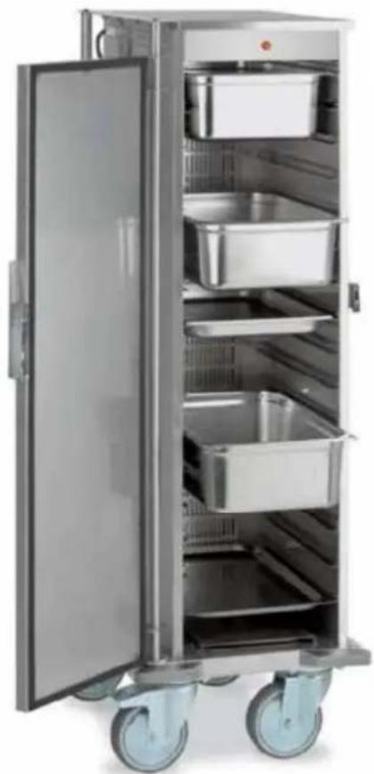
natural_image
Interior view of a stainless steel multi-compartment kitchen cabinet with open doors and wheels (no visible text or labels)
Instruction manual
natural_image
Line drawing of a rectangular industrial cart with wheels and side panels (no text or symbols)Summary
Instruction manual
THERMOVEGA 1/1 C16
THERMOVEGA 1/1 L10
THERMOVEGA 2/1 C16
THERMOVEGA 1/1 SH C10
THERMOVEGA BAKE
EN
- Instruction warnings....2
- Safety and Right Use Warnings....2
- Warranty....2
3.1 Unpacking....2 - Appliance Start Up....3
- Technical Features....3
- Troubleshooting....3
- Cleaning and maintenance....4
- Disposal 4
- Spare parts....4
- Wiring diagrams....5
1. Instruction warnings
User has to hold the whole instructions. User must store up this document in case of use. The manufacturer is not responsible of any damage incurred due to the failure of improper use of this manual.
All measures in this manual are in mm.

2. Safety and Right Use Warnings
These products meet the latest technological evolutions and current safety guidelines. Trolley line THERMOVEGA, object of this booklet, is designed to be in compliance with directives and field laws, in order to guarantee a safe and reliable product.
Any other use will be considered inappropriate to the original destination. The producer is not responsible of any damage caused by an improper use. Responsibility lies only on user. A proper use also includes compliance with the instructions for use and installation
and any additional documentation as well as the conditions of inspection and maintenance.
3. Warranty
We thank you for purchasing a this product, designed and produced for a professional environment. Due to commercial and construction requirements, the manufacturer reserves the right to make changes in order to enhance the quality and use of product. The producer, in compliance with European Community legislation, grants its products for 12 months. This warranty does not include electrical parts, labour and all replacements related to an improper use of the good. Any manipulation carried out automatically excludes the liability of the manufacturer. The products or parts to be replaced or repaired for unequivocal defects in workmanship and materials used must be in a “free port” at the offices of the producer, who after a careful inspection, will repair or replace them. The repairs are carried out exclusively at the headquarters of the manufacturer, and none cost incurred by the customer for repairs will be refunded by the manufacturer unless explicitly agreed.
ANY MANIPULATION AUTOMATICALLY EXCLUDES THE MANUFACTURER'S LIABILITY AND THE WARRANTY ON THIS PRODUCT.
3.1 Unpacking
This item is packed and shipped assembled. The manufacturer declines every responsibility for damages of someone or something caused by the failure to comply with the instructions of this manual. Do not make any structural change to the trolley.
The elements composing the trolley (plastic, polyurethane foam, bubble wrap, Styrofoam, cardboard and so on) must be kept away from children as potential sources of danger and must be collected and disposed off separately in accordance with local regulations.
The manufacturer declines every responsibility of damage of someone or something caused by the failure to comply with the instructions of this manual.
After the unpacking of the item from its packing, proceed by removing the adhesive plastic tape before starting up the product. Any residual glue has to be removed carefully (do not use abrasive cleaners).
The device is designed to run on AC to the voltage specified on the technical data plate (located on the bottom of the tank).
The grounding line is marked by the colours yellow/green and must not be interrupted.
The device is provided with a cable in accordance with the CE regulations and with a schuko plug (that can be replaced, when necessary, with a different plug, suitable for the specified wattage and in accordance to the current regulations and guidelines; when necessary, replace the provided cable with a new one with the same features)
Before switching on the appliance
- Check if the electrical system can withstand the appliance's load (WATT as indicated on the technical plate)
- Make sure that the electrical system is provided with ground connection according to the current norms and guidelines.
- Connect the appliance with the ground network through a cable connected to the specific screw placed on the external casing of the appliance.
4. Appliance Start Up
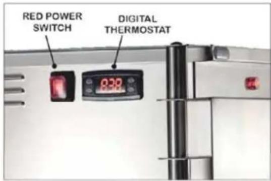
Once ready to start the appliance, plug the device in the electrical system and press the red power switch placed on the upper part of the unit.
As you turn on the appliance the thermostat display will flash and then it will displa 90°C".
Once started up, the appliance reaches the pre-set temperature quickly (depending by the starting temperature, the room temperature and the exposure of the buffet trolley).
The thermostat is set from the manufacturer on +75 °C for a optimal use of the device. Use the attached instructions to change the settings of the digital thermostat.

WARNING: Once the thermostat reaches the max standard temperature (75°C) set from the manufacturer, the inside temperature will increase up to about 15°C (according to the situation, to the quantity of product inside the appliance, etc...). This is not a defect but the result of the double insulated walls effect which retain the heat for a long time even
FIRST SERVICE WARNINGS:
Some unpleasant smells and smoke could come out the appliance during the first use of the heated appliance because of the production traces of grease, FOR THE FIRST SERVICE TURN ON THE APPLIANCE (WITH NOTHING INSIDE) AND LEAVE THE DOOR OPEN FOR SOME MINUTES, in order to eliminate any residual that could affect the food inside.
WARNING:
Once turned on, the appliance will reach the desired temperature very quickly. In order to avoid any inconvenience, turn the device on only shortly before starting the service and turn it off shortly after the end. Do not make any structural change to the appliance.
5. Technical Features
| Thermovega 1/1 C16 | Thermovega 1/1 L10 | Thermovega 2/1 C16 | Thermovega 1/1 SH C10 | Thermovega Bake | |
| Heating elements | 1700 W | 1700 w | 1700 W | 700 W | 700 W |
| Power supply | 230 V | ||||
| Temperature Range | +30°/+75°C | ||||
| Shape guides | 16 x "type" | 10 x "type" | 16 x "type" | 10 x "C" type | 10 x "type" |
| Weight (Kg) | 80 | 80 | 120 | 45 | 50 |
6. Troubleshooting
| Problem Possible reasons Solutions | ||
| The trolley does not heat up | Power cut Check the power presence in the electricity network. | |
| Heating element is burned Contact the retailer | ||
| Thermostat is broken Contact the retailer | ||
| Switch button is broken | Contact the retailer | |
| Power cable is worried-out | Replace the cable with a new one with the same technical features | |
7. Cleaning and maintenance

WARNING:
Before any cleaning operation un plug the device from the electrical system. Never wash the appliance with water jets in order to prevent water seepage inside the electrical components.
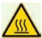
Before any cleaning operation wait for the appliance to be cooled down (wa it at least one hour from the end of the service).
The thermic trolley should be cleaned with specific cleansers for stainless steel. The trolley is supplied with a safety thermostat set to 150^ C, which works in case of malfunction of the electronic thermo stat. To reset the system following an interruption due to the safety thermostat, unscrew the top and push the red button on it.
8. Disposal
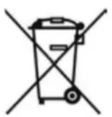
At the end of its life cycle, the device must be disposed according to the current regulations and must, where possible, be disassembled and disposed according to the nature of its various components. The packing materials (plastic, foam, bubble wrap, styrofoam, cardboard etc) must be kept away from children as potential sources of danger and must be collected and disposed separately in accordance with the local regulations.
This marking shown on the product or its literature, indicates that it should not be disposed with other household wastes at the end of its working life.
To prevent possible harm to the environment or human health from uncontrolled waste disposal, please separate this from other types of wastes and recycle it responsibly to promote the sustainable reuse of material resources. Household users should contact either the retailer where they purchased this product, or their local government office, for details of where and how they can take this item for environmentally safe recycling.
9. Spare parts
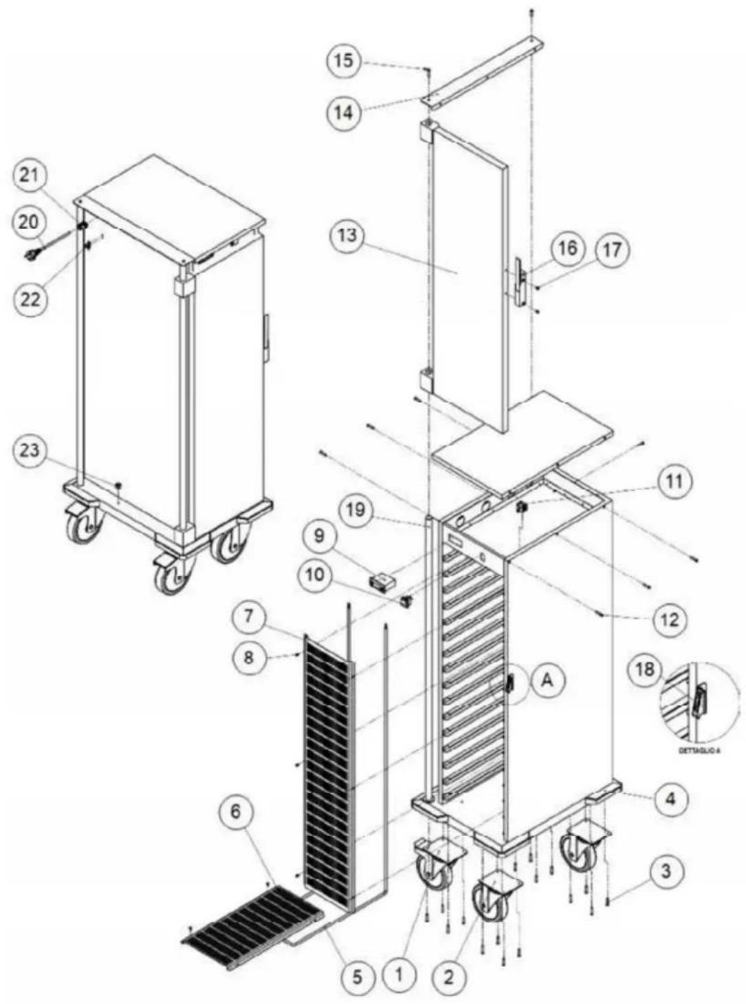
Please find attached assembly and components list at the end of this booklet.
10. Wiring diagrams
THERMOVEGA 1/1 C16- THERMOVEGA 1/1 L10
THERMOVEGA 1/1 SH C10 - THERMOVEGA BAKE
THERMOVEGA 2/1 C16
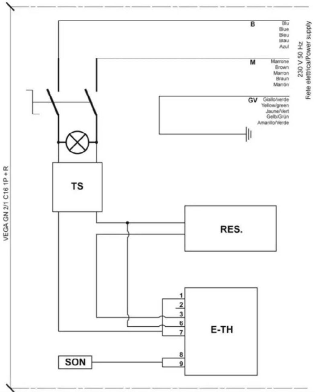
flowchart
graph TD
    A["SON"] --> B["TS"]
    B --> C["E-TH"]
    C --> D["RES."]
    D --> E["GSV"]
    E --> F["M: Marrone, Brown, Marron, Braun, Marrón"]
    E --> G["B: Blu, Blue, Bleu, Blau, Azul"]
    E --> H["M: Giallo/verde, Yellow/green, Jaune/Vert, Gelb/Grün, Amarillo/Verde"]
    style A fill:#f9f,stroke:#333
    style B fill:#ccf,stroke:#333
    style C fill:#cfc,stroke:#333
    style D fill:#fcc,stroke:#333
    style E fill:#ffc,stroke:#333
    style F fill:#fcc,stroke:#333
    style G fill:#fcc,stroke:#333
    style H fill:#fcc,stroke:#333
| Ref. | Description |
| TS | Safety Thermostat |
| E-TH Electronic Thermostat | |
| SON | Probe Electronic Thermostat |
| RES | Heating Element |
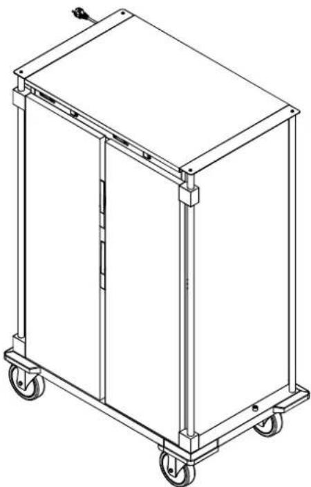
natural_image
Line drawing of a rectangular industrial cart with wheels and side panels (no text or symbols)Index
Article:
THERMOVEGA 1/1 C16
THERMOVEGA 1/1 L10
THERMOVEGA 2/1 C16
THERMOVEGA 1/1 SH C10
THERMOVEGA BAKE
FR
THERMOVEGA 1/1 SH C10 - THERMOVEGA BAKE
THERMOVEGA 2/1 C16
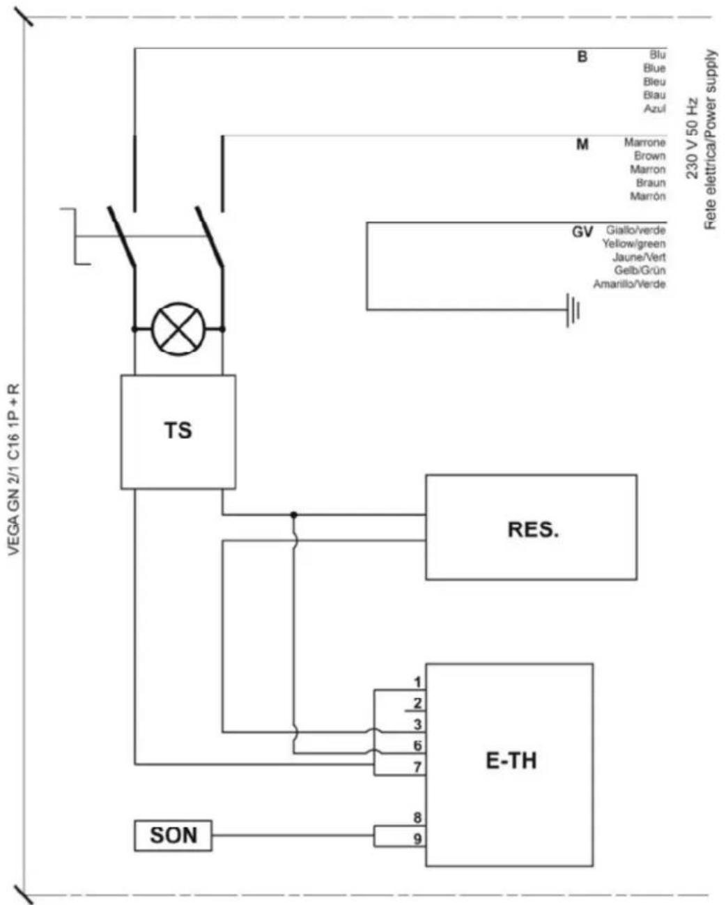
flowchart
graph TD
    A["SON"] --> B["E-TH"]
    B --> C["RES."]
    C --> D["TS"]
    D --> E["BS"]
    E --> F["230 V 50 Hz Fete eletrica/Power supply"]
    style A fill:#f9f,stroke:#333
    style B fill:#ccf,stroke:#333
    style C fill:#cfc,stroke:#333
    style D fill:#fcc,stroke:#333
    style E fill:#cff,stroke:#333
    style F fill:#ffc,stroke:#333
| THERMOVEGA 2/1 C16 | |||
| Ref. | Cod. | Q.ty Description | |
| 1 | RF 160 | 2 | Castor with brake ∅160 |
| 2 | RS 160 | 2 | Standard castor ∅160 |
| 3 16 Screws | |||
| 4 4 Plastic bumpers | |||
| 5 1 Heating element W2000 | |||
| 6 1 | Horizontal grid | ||
| 7 1 | Vertical grid | ||
| 8 10 | Grid screws | ||
| 9 1 | Electronic thermostat | ||
| 10 1 | Power switch | ||
| 11 1 | Safety Thermostat | ||
| 12 7 | Top screws | ||
| 13 1 | Door | ||
| 14 1 | Push handle bracket | ||
| 15 2 | Push handle bracket screws | ||
| 16 1 | Door handle | ||
| 17 2 | Door handle screws | ||
| 18 1 | Hook lock | ||
| 19 2 | Push handle | ||
| 20 1 | Schuko cable | ||
| 21 1 | Cable gland | ||
| 22 1 | Cable clamp | ||
| 23 1 | Doorstopper | ||
THERMOVEGA 1/1 C16 – THERMOVEGA 1/1 L10
| THERMOVEGA 1/1 C16 -THERMOVEGA 1/1 L10 | |||
| Ref. | Code | Quantity | Description |
| 1 RF 160 2 Castor with brake ∅160 | |||
| 2 RS 160 2 Standard castor ∅160 | |||
| 3 | 16 $ | ||
| 4 4 Plastic bumpers | |||
| 5 | 1 | Heating element W2000 | |
| 6 | 1 | Horizontal grid | |
| 7 1 | Vertical grid | ||
| 8 | 10 | Grid screws | |
| 9 1 | Electronic thermostat | ||
| 10 | 1 | Power switch | |
| 11 | 1 | Safety Thermostat | |
| 12 | 7 | Top screws | |
| 13 | 1 | Door | |
| 14 | 1 | Push handle bracket | |
| 15 | 2 | Push handle bracket screws | |
| 16 | 1 | Door handle | |
| 17 | 2 | Door handle screws | |
| 18 | 1 | Hook lock | |
| 19 | 2 | Push handle | |
| 20 | 1 | Schuko cable | |
| 21 | 1 | Cable gland | |
| 22 | 1 | Cable clamp | |
| 23 | 1 | Doorstopper | |
Installation and operating instructions
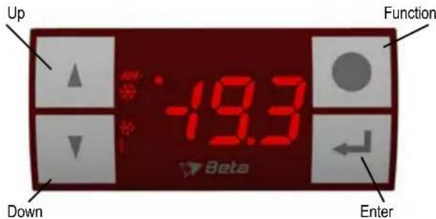
RC31 II Series Electronic On/Off controllers
- KEYBOARD FUNCTIONS
Enter: to activate the programming mode and to view and to confirm the new values.
Function: 1) to show the Haccp records; 2) pushed for 5 seconds, to start or stop manually the defrost (if LFc=0) without waiting dSd, or to switch on/off the controller (if LFc=1). The off mode, or stand-by, is stored in memory; 3) in programming mode, to quit the parameters menu without saving the new values (escape command); 4) during an alarm event, to switch off the optional internal buzzer and relay.
Up: 1) to display, for a few seconds, the probe 1 snap temperature; 2) during the programming mode, to scroll the parameters menu and to increase the value of the selected parameter.
Down: 1) pushed together with the Enter key, for 5 seconds, to lock / unlock the keyboard; 2) during the programming mode, to scroll the parameters menu and to decrease the value of the selected code.

Light on → compressor is running (output relay K1 is on, Act=0); Flashing → waiting for a time delay to switch on the compressor.

Light on → heater is running (output relay K1 is on, Act=1); Flashing → waiting for a time delay to switch on the heater.

Light on → defrost action is running.
The upper left point is flashing in programming mode and is lit on if an external contact is active (digital input) or during the stand-by mode. The number "1" indicates the current probe temperature shown on the display.
1.00 GENERAL DESCRIPTION AND INSTALLATION NOTICE
The RC31 models are controllers specifically designed to manage static refrigerating units, for positive (or normal) temperatures. Simply modifying a parameter, it is possible to select between direct and inverse action, to control also heating appliances.
The controllers have 1 analog input for ntc/ptc temperature probe and 1 output relay for cooling or heating control, optionally a digital-input for an external switch and optionally 1 alarm relay or buzzer. In cooling mode, it performs defrost by stopping the compressor for a defined time. RC31 detects temperature alarm conditions referred to the temperature probe, storing into its memory the last tree events (Haccp feature). Through the TTL port, an external master device can read and write the RC31 registers, in order to monitor and change its functioning.
1.10 Installation notice
The installation must be done only by specialized personnel in according to the rules in force in the country where the controllers are used. The instrument is conceived for controlling and regulation, not for safety function. It must be installed in a place protected from extreme vibrations, impact, water, corrosive gases, and where temperature and moisture do not exceed the maximum rating levels indicated in the specifications. The probe is not waterproof, it should be placed with its head upward, so that drops would not penetrate into the bulb and damage the sensor. Maintain the length of the electrical wires as short as possible in order to keep the noise picked by them at low level; otherwise a shielded wire will be needed, and the shield will be connected to the ground. Pay attention to connect correctly the probe PTC300 type, it is polarized: cathode must be at ground level.
1.20 ELECTRICAL WIRING
We recommend to protect the power supply of t he controller from electrical noise, spikes and especially from voltage surges and drops. This can be easily done following these recommendations:
-separate the power supply of the loads (compressor, heaters, fans) from the power supply of the controller. This alleviates problems related to voltage dips that can arise during the switch-on of the loads, that may disturb the controller's microprocessor causing unexpected resets.
-the cables of the probes and the ones of the controller supply or the loads must be separated, to reduce spikes and noise on the sensor. This improves the stability of the reading and it also makes the commutation of the device more accurate.
1.30 CRITICAL ENVIRONMENT
For applications in heavy industrial environment these rules should be followed.
- After having identified the source of noise spikes, it is recommended to apply a line filter to the source in question of the type specifically designed to solve EMC (Electromagnetic compatibility) related problems. Sometimes it may be sufficient an RC type filter, also called «snubber», connected in parallel to the external relay coils, or circuit breakers.
- An independent power supply should be used to power the device in extreme conditions.
ATEX reserves the right to make changes without further notice to any products herein to improve reliability, function or design. ATEX does not assume any responsibility for any improper use or application of any product or circuit described herein. ATEX products are not designed, intended, or authorized to be use as components in systems or applications intended to support or sustain life, or for any other application in which the failure of the ATEX product could create a situation where personal injury or death may occur.
ATEX Industries srl
33078 S. Vito al Tagliamento – PN Italy
Tel.: +39 0434 85183 r.a.
web: www.atex.it - e-mail : beta@atex.it
2.00 TECHNICAL SPECIFICATIONS
POWER : 230 Vac ±10% 50/60 Hz (3VA max);
SUPPLY or 115 Vac ±10% 50/60 Hz (3VA max);
or 12 Vac/dc ±10% (150mA max) (use only SELV power s.);
or 9..24 Vac/dc (use only SELV power supply).
INPUTS: 1 temperature sensor, 1 Digital-In external contact (max 1mA);
types: Ntc standard 10Kohm@25°C Beta=3435-25/85 (-40..+125°C);
Ptc 990ohm@25°C KTY81(2)-121 (meas. range -50..+150°C);
Ptc 1Kohm@100°C KTY84-130 (measure range -40..+300°C);
Pt1000 1Kohm@0°C 2-wires (measure range -50..+350°C).
OUTPUTS: 1 spdt relay 250Vac 8A max resistive (K1 - main relay);
1 spst relay 250Vac 5A max resistive (optional alarm);
(other main relay power are available: 16A, 2HP)
SERIAL PORT: TTL level, ModBus protocol, RTU type, 9600 baud, 8bit char, even parity, 1 bit stop;
DISPLAY: 3 digit LED, 14 mm height, high intensity red;
MEASURING RANGE: -50...+300 °C / -50 ... +572 °F (if Ptc300);
- resolution: 0.1 °C / 0.1 °F (within -19.9 .. +99.9);
- accuracy @25°C: ±0.5 °C + 1 digit;
To define the max measure error, add the accuracy of the connected probe. - connections terminal block with screw for max 2.5mm ^4 gauge wire;
- operating temperature: -10 ... +60 °C;
- storage temperature: -25 ... +70 °C;
- storage humidity: 30 ... 90 % r.H., non condensing;
- plastic casing (PC+ABS rear box, PC frontal panel);
- frontal panel IP65, if appropriate mounting gasket;
- max temperature of the switch head: 60 °C;
- pollution degree: 2;
- rated impulse voltage: 2.5 KV;
- PTI of insulating material: 175 (circuit board 250);
- class of protection against electric shock: II (for correct install.);
- class of protection against voltage sourges: category II;
- type of disconnection: 1.B micro disconnection (relay).
Typical terminal connections (See the label on top of the instrument for the right diagram connection).
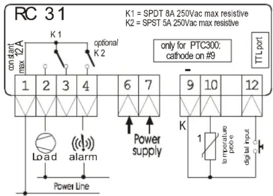
flowchart
graph TD
    A["RC 31"] --> B["K1 = SPDT 8A 250Vac max resistive"]
    A --> C["K2 = SPST 5A 250Vac max resistive"]
    B --> D["12A con start max K1"]
    C --> E["6 7"]
    D --> F["1 2 3 4"]
    E --> G["9 10 12"]
    F --> H["Load"]
    G --> I["Power supply"]
    H --> J["Power Line"]
    I --> K["alarm"]
    J --> L["temperature power"]
    K --> M["digital input"]
    L --> N["TTL port"]
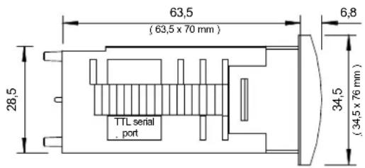
Frontal dimensions: 34.5 x 76.5 mm
Mounting hole dim.: 29 x 71 mm
3.00 SETTING THE RC31
3.10 Menu Level 1 - Adjust the main (SEt) and secondary SET POINT (desired temperature value)
1) Press and release the Enter key “↓”, SET is displayed. The upper point will flash to indicate programming mode entering. To view/change St2, press “▲” or “▼” to move to St2 (energy saving secondary Set Point);
2) Press and release “←” to view the Set Point value, adjust it by using “▲” or “▼” (it is only possible values inside the SLo and SHi range);
3) Press and release “-” to confirm the data, after 15sec. the RC31 will leave programming mode and the new data will be stored in the memory. When tdi=3, adjust the SEt value simply by pressing the “Up” or “Down” keys. Then press the “Enter” key to return to the point 1).
3.20 Menu Level 2 - Adjust all the other OPERATING PARAMETERS
1) Press the Enter key “-” and hold it for 6 seconds. The upper point will flash to indicate programming mode entering. If no password is set (PSS=0), the code of the first variable SHy will appear, go to point 3. If password is set, will appear “PAS” request;
2) (password request) Press and release the Enter key “-”, “0” will be shown; press “▲” to enter the right password value and then press and release the Enter key to confirm it. If the value entered does not match the stored password (PSS), the controller exits the programming mode;
3) (SHy showed) press “▲” or “▼” to scroll all the parameter codes;
4) While a code is displayed press and release the Enter key “←” to view its content, adjust it by pressing “▲” or “▼”;
5) Press and release “☐” to confirm the data, after 15sec. the RC31 will quit the programming mode and the data will be stored in the memory.
WARNING:
- the instrument must not be reset before leaving the programming mode, otherwise the new setting will be lost;
- if the "Function" key is pressed during the programming mode, the user will exit the progr. mode without saving, RC31 will lose the new setting;
- the controller automatically interrupts any setting operation if any push-button isn't pressed for at least 15 seconds and store the current data;
- after having modified any parameter the controller must be restarted (unplug and plug again) .
3.30 Keyboard locking
Press and hold both the Enter key “J” + the Down key “▼” for 6 second, in order to lock and unlock the keyboard (the upper-left point will flash).
If the controller shows "Pof" it means the keyboard is locked, if it shows "Pon" the keyboard is unlocked.
When the keyboard is locked it is possible to view any parameters value but not to change them.
3.40 How to show the stored alarm temperatures (Haccp feature)
The RC31 stores the last 3 temperature alarm events: the temperature of probe 1 has been lower than ALo or higher than AHi.
- when the controller is showing the temperature (i.e. not in programming mode), press and release the "Function" key;
- it will show "HcP" (Haccp) and, if any alarm data are stored, it will show "AL1", min/max temperature reached and for how long (minutes) the temperature 1 was over ALo or AHi, then "AL2", min/max alarm ... . AL1 is referred to the most recent event. AL3 is the oldest.
When the RC31 is showing the Haccp data, pressing the "Function" key for 5 seconds will erase the alarm data stored (it will show "--").
The controller will show only data for alarms of events which have come back to normal. If an alarm is running, it could be ended decreasing the ALo or increasing the AHi value. At the end of an alarm the RC31 stores the Haccp data in its memory.
During the defrost actions there is no alarm recording. RC31 doesn't have a battery inside, if power fails occurs it does not check/record any data.
Changing the temperature measure unit ("unt" param.), the logged temperatures / parameters values reflect unit set in the past (not convert).
4.10 MAIN OUTPUT parameters
| Param. code | Description | Range Default | |
| SEt | Set point: it is the desired temperature. | SLo .. SHi °C | 5 °C |
| St2 | Secondary set point. Useful for the external contact function.When Eio=±3, switching an external contact, it is possible to change the active Set point value between SEt and St2. | SLo .. SHi °C | 8 °C |
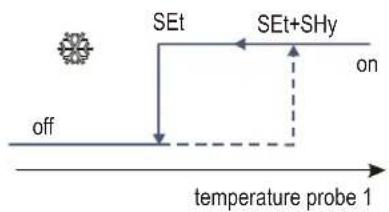
| SHy | Set point Hysteresis (ex HyS). Delta temperature value to avoid regulating oscillations (see figures below).(i.e.: if act=0, the compressor switches off at SEt and switches on at SEt+SHy value). | 0.1 .. 40 °C | 2 °C |
| SLo | Low Set Point limit (ex LoS).It is the min value of SEt parameter range. The user cannot select a SEt value lower than SLo. | -50 .. SHi °C | -40 °C |
| SHi | High Set Point limit (ex HiS).It is the max value of SEt parameter range. The user cannot select a SEt value higher than SHi. | SLo .. 285 °C | 110 °C |
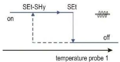
| Act | Action of the main output relay K1: direct for cooling systems, inverse for heating control.0: direct action (refrigeration). As temperature rises over (Set+SHy), it switches on the K1 output (for a compressor);1: inverse action (heating). As the temperature falls below (Set-SHy), RC31 switches on the K1 output (for a heater). | 0 .. 1 | 0 |
| rA1 | Anticycle retard (ex Acy), useful for compressor drive. When the K1 output is switched-off, the controller waits at least rA1 minutes to switch on again the K1 relay. It is also the delay for the first activation of the K1 relay at power on. | 0 .. 20 minutes | 0 m |
| ro1 | Retard to switch on the K1. It is the delay to switch on the K1 relay from the request to activate it.When the temperature requires to activate the K1 output, the software starts to waiting ro1 minutes before switching on the output relay. This delay is not considered when PF1. After defrost, K1 output waits also ro1 (see also dAd). | 0 .. 20 minutes | 0 m |
| PEc | Probe 1 error, output K1 mode (ex CPF). If there is a probe 1 fault (temperature out of range, shortcircuit or probe disconnected, RC31 measur.circuit fault) the RC31 starts to manage the K1 relay by time and shows PF1 on display.0: K1 always off; 1: K1 always on; 2: K1 on for PE1 minutes and off for PE0 minutes. | 0 .. 2 | 2 |
| PE1 | Probe 1 error, K1 relay on (ex Con). The time to switch on the K1 relay when there is a PF1 error (if PEc=2). | 0 .. 45 minutes | 15 m |
| PE0 | Probe 1 error, K1 relay off (ex Cof). The time to switch off the K1 relay when there is a PF1 error (if PEc=2). | 0 .. 45 minutes | 30 m |
Act=0 - direct action
cooling mode, K1 relay drives a compressor
flowchart
graph TD
    A["off"] --> B["SEt"]
    B --> C["SEt+SHy"]
    C --> D["on"]
    style A fill:#f9f,stroke:#333
    style B fill:#ccf,stroke:#333
    style C fill:#cfc,stroke:#333
    style D fill:#fcc,stroke:#333
Act=1 - inverse action
heating mode, K1 relay drives a heater
flowchart
graph TD
    A["SEt-SHy"] --> B["SEt"]
    B --> C["off"]
    D["on"] --> A
    E["temperature probe 1"] --> F
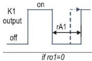
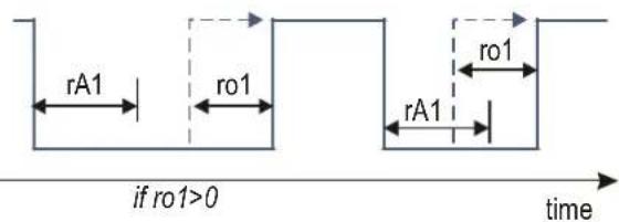
WARNING: during the installation, take care to set proper rA1 value to avoid compressor or relay faults.
4.20 ALARM parameters
The temperature alarm events are always linked to the probe 1. The alarm hysteresis is 0,4 °C fixed.
| Param. code | Description | Range | Default |
| AtP | Alarm type values.0: ALo, AHi are absolute temperature values; 1: ALo, AHi are temperature values relating to the SET value. | 0 .. 1 | 0 |
| ALo | Low temperature threshold alarm (ex LoA). If the temperature goes below this value (ALo-0,4), the controller activates an alarm signal on the display and starts recording the minimum temperature and the duration of the alarm (Haccp function). Also it switches on internal buzzer and alarm relay, if present (optional). | AtP=0, -50..(AHi-1) AtP=1, -50 .. -0.5°C | -40 °C |
| AHi | High temperature threshold alarm (ex HiA). If the temperature goes up over this limit value (AHi+0,4), the controller activates an alarm signal on the display and starts to record the max temperature and the time duration of the alarm signal. Also it switches on internal buzzer and alarm relay, if present (optional). | AtP=0 (ALo+1)..150 AtP=1 0.5 .. 285°C | 110 °C |
| Adi | Alarm delay at the power on. The RC31 does not check any temperature alarm for Adi hours from the power on. | 0 .. 10 hours | 0 h |
| ALd | Alarm delay on running time.The temperature must be in the alarm range for ALd minutes to switch on the alarm signal. | 0 .. 120 minutes | 0 m |
| AdF | Alarm delay after defrost. After the end of any defrost, the RC31 waits AdF minutes before checking any temp. alarm. | 0 .. 180 minutes | 0 m |
| Ad0 | Alarm delay after de-activation of the external contact (digital input).I.e.: after closing the room door, the RC31 waits Ad0 minutes before checking the temperature for alarm. | 0 .. 240 minutes | 0 m |
| Ad1 | Alarm delay from the activation of the external contact. The delay count starts immediately without waiting Eid.I.e.: after opening the room door, the RC31 waits Ad1 minutes before checking the temperature for alarm | 0 .. 120 minutes | 0 m |
Note: The alarm signal management is disabled during the defrost actions (no start, nor stop alarm).
When AtP=1, ALo & AHi are always referred to the SEt value, also if St2 is activated by an external input.
4.30 DEFROST parameters
The RC31 does not perform any defrost action when inverse action is set (if act=1).
| Param. code | Description Range Default | ||
| dPt | Defrost time period. It is the period of time between two defrost actions. | 1 .. 240 (dtS) | 6 h |
| ddt | Defrost duration. It is the duration of each defrost action. If ddt=0 the defrost function is disabled. | 0 .. 240 (dtS) | 30 m |
| dtS | Defrost time scale (ex tiS). It changes the time scale of dPt and ddt.0: dPt hours, ddt minutes; 1: dPt minutes, ddt seconds; | 0 .. 1 0 | |
| dSd | Defrost start delay. It is a delay between the time to start of the defrost action and its real beginning (switch off of the output). At the power on of the controller, it starts the first defrost action after dPt hours + dSd minutes (and the successive starts after dPt). If an external contact activates the defrost action (if Eio=±4), it starts after dSd minutes. | 0 .. 120 minutes | 0 m |
| dAd | Delay to switch on the compressor after a defrost end (ex Add). Dripping Time. After a defrost cycle, the compressor is stopped to assure dripping of possible water still present in the evaporator. | 0 .. 120 minutes | 0 m |
| ddd | Displayed during the defrost action.0: the temperature at the defrost start; 1: the message “dEF”; 2: the SET value; 3: the currently temperature.When 0, 1, 2, the value will be shown on the display until the controller will have reached again the Set Point value. | 0 .. 3 0 |
4.40 Various parameters
| Param. | Description Range Default | ||
| Eio | External contact digital input operation (ex dio).- Negative value: digital input signal is active if external contact is closed.- Positive value: dig. input is active if contact is opened.0: disabled; ±1: not allowed; ±2: door open, switch off the main output K1 relay; ±3: St2 is the desired temperature (instead of SET); ±4: start defrost (for another defrost start command, de-activate and activate again the ext.contact); ±5: toggle to stand-by mode (the off state is not stored in memory); ±6: external alarm, switch off all the relays, switch on the optional internal buzzer and relay. | -6..6 | 0 |
| Eid | Ext. contact input delay (ex did).From the activation of the external contact, RC31 waits Eid minutes to start the Eio function. | 0..60 minutes | 0 m |
| Prt | Probes type.0: probe input line able to read 10Kohm NTC temperat. sensor; 1: no avail.; 2: 990ohm PTC; 3: PTC300; 4: PT1000. | 0..4 0 | |
| rES | Display temperature resolution.0: the temperature is shown in tenths of degrees; 1: temperature without decimal point. | 0..1 0 | |
| Unt | Temperature unit measurement. 0: Celsius degree; 1: Fahrenheit degree.(changing Unt, RC31 doesn't match any parameter. Rearrange temperature param. values to adjust the control) | 0..1 0 | |
| oF1 | Temperature probe 1 calibration. To modify the temperature value measured by the probe 1. | -10..10 °C | 0 °C |
| tdi | Temperature displayed. 0: temperature probe 1; 2: SET value; 3: the SET value is displayed and it can be adjusted simply by pressing the "Up" or "Down" keys (without enter into menu level 1).When tdi=0 or 2, pressing the "Up" key it displays for a few seconds the currently temperature measured by probe 1.When tdi=3, pressing the "Enter" key it displays for a few seconds the currently temperature measured by probe 1. | 0..3 0 | |
| utd | Update temperature filter. Different averages are performed to avoid noise spikes on the probe measurements.0: filter disabled (3 measures displayed/seconds); 10: the temperature average is evaluated on the longest time span. | 0..10 | 5 |
| LFc | Long pushing Function configuration.0: pushing for 5s the "Function" key start/stop defrost;1: pushing for 5s the "Function" key toggle on/off the RC31 (stand-by mode activation). | 0..1 0 | |
| PSS | Password setting. It is possible to set a password to access on the 2nd menu parameter.0: password request disabled. | 0..999 | 0 |
| LVS | Low voltage sensing. To improve the functioning, RC31 continuously verifies the power supply. 0: function disabled;1: short voltage drop is not detected (min sensitivity); 10: short voltage drop is detected (max sensitivity). | 0..10 | 1 |
| nAd | Slave device number address. It is the address of the controller in a bus network with ModBus-RTU protocol.0: serial port is disabled. When a key is pushed or in programming mode, RC31 does not always answer to the serial port. (after having changed this value, the RC31 must be restarted) | 0..247 | 0 |
5.00 Troubleshooting
| Message | Description, cause | Output |
| Hit | The measured temperature of probe 1 is higher than the (AHi+0,4) parameter value. If AtP=1, the temperature is higher than (SEt+AHi+0,4). | The main K1 output doesn't change.Switch on the optional buzzer or relay.*The controller starts to save the alarm data (haccp). |
| Lot | The measured temperature of probe 1 is lower than the (ALo-0,4) parameter value. If AtP=1, the temperature is lower than (SEt-ALo-0,4). | The main K1 output doesn't change.Switch on the optional buzzer or relay.*The controller starts to save the alarm data (haccp). |
| ALE | Extern alarm. When Eio=±6 and the external contact is active. | The main output K1 relay is switched off.Switch on the optional buzzer or relay. |
| PF1 | The probe input line is opened/disconnected or short circuited.The measured temperature is out of the range. | K1, compressor (or heater) operation is according to PEc.Switch on the optional buzzer or relay. |
| EEP | Memory error.The parameter list could be corrupted. The fridge control is not assured.Immediately check every parameter value, save the correct value, restart the RC31. | Not predictable. |
| LoV | Low voltage detection on the power supply. Check the voltage value, noises (par. 1.20). | All the outputs are switched off. |
| dOP | Door opened. When Eio = ±2 and the external contact is active. | Switch off the main output K1 relay. |
| OFF | The controller is going to switch off the outputs and display (stand-by mode). | All the output relays are switched off. |
- Summary
- Instruction warnings
- Safety and Right Use Warnings
- Warranty
- ANY MANIPULATION AUTOMATICALLY EXCLUDES THE MANUFACTURER'S LIABILITY AND THE WARRANTY ON THIS PRODUCT.
- Unpacking
- Before switching on the appliance
- Appliance Start Up
- FIRST SERVICE WARNINGS:
- WARNING:
- Technical Features
- Troubleshooting
- Cleaning and maintenance
- Disposal
- Spare parts
- Wiring diagrams
- Index
- FR
- THERMOVEGA 1/1 C16 – THERMOVEGA 1/1 L10
- Installation and operating instructions
- - KEYBOARD FUNCTIONS
- GENERAL DESCRIPTION AND INSTALLATION NOTICE
- Installation notice
- ELECTRICAL WIRING
- CRITICAL ENVIRONMENT
- TECHNICAL SPECIFICATIONS
- SETTING THE RC31
- Menu Level 1 - Adjust the main (SEt) and secondary SET POINT (desired temperature value)
- Menu Level 2 - Adjust all the other OPERATING PARAMETERS
- Keyboard locking
- How to show the stored alarm temperatures (Haccp feature)
- DEFROST parameters
Brand : CaterChef
Model : 710105
Category : Uncategorized