
Pro NMS - NAS Edimax - Free user manual and instructions
Find the device manual for free Pro NMS Edimax in PDF.


| Type de produit | Network Attached Storage (NAS) |
| Dimensions (approx.) | 200 x 150 x 50 mm |
| Poids (approx.) | 1.2 kg |
| Alimentation | 12 V DC, 2 A, 24 W |
| Fonctions principales | Partage de fichiers, sauvegarde, streaming multimédia, accès à distance, support RAID |
| Entretien et nettoyage | Essuyer avec un chiffon sec, maintenir une ventilation adéquate |
| Sécurité | Éviter l'humidité, utiliser l'adaptateur secteur fourni |
| Pièces détachées et réparabilité | Disques durs remplaçables, adaptateur secteur remplaçable |
| Informations générales | Prend en charge plusieurs utilisateurs et protocoles réseau |
Frequently Asked Questions - Pro NMS Edimax
User questions about Pro NMS Edimax
0 question about this device. Answer the ones you know or ask your own.
Ask a new question about this device
Download the instructions for your NAS in PDF format for free! Find your manual Pro NMS - Edimax and take your electronic device back in hand. On this page are published all the documents necessary for the use of your device. Pro NMS by Edimax.
USER MANUAL Pro NMS Edimax
No.3, Wu-Chuan 3rd Road, Wu-Gu, New Taipei City 24891, Taiwan
Email: support@edimax.com.tw
Edimax Technology Europe B.V.
Fijenhof 2, 5652 AE Eindhoven, The Netherlands
Email: support@edimax.nl
Edimax Computer Company
3350 Scott Blvd., Bldg.15 Santa Clara, CA 95054, USA
Live Tech Support: 1(800) 652-6776
Email: support@edimax.com
Contents
I. Product Informaon....5
II. Quick Setup.... 6
III. Soware Layout....12
IV. Features....19
IV-1. LOGIN, LOGOUT & RESTART 19
IV-2. DASHBOARD 21
IV-2-1. System Informaon 22
IV-2-2. Devices Informaon....22
IV-2-3. Managed AP....23
IV-2-4. Managed AP Group....24
IV-2-5. Acve Clients ....25
IV-3. ZONE PLAN.... 26
IV-4. NMS MONITOR 29
IV-4-1. Access Point 29
IV-4-1-1. Managed AP....29
IV-4-1-2. Managed AP Group....31
IV-4-2. WLAN 33
IV-4-2-1. Acve WLAN 33
IV-4-2-2. Acve WLAN Group 34
IV-4-3. Clients .... 34
IV-4-3-1. Acve Clients .... 34
IV-4-4. Rogue Devices....35
IV-4-5. Informaon....36
IV-4-5-1. All Events/Acvies 36
IV-4-5-2. Monitoring....37
IV-5. NMS Sengs....38
IV-5-1. Access Point 38
IV-5-2. WLAN 49
IV-5-3. RADIUS....53
IV-5-4. Access Control 59
IV-5-5. Guest Network....62
IV-5-6. Zone Edit....66
IV-5-7. Firmware Upgrade....68
IV-5-8. Advanced 69
IV-5-8-1. System Security....69
IV-5-8-2. Date & Time 69
IV-6. Local Network 71
IV-6-1. Network Sengs 71
IV-6-1-1. LAN-Side IP Address....71
IV-6-1-2. LAN Port Sengs....74
IV-6-1-3. VLAN 75
IV-6-2. 2.4GHz 11bgn....76
IV-6-2-1. Basic 76
IV-6-2-2. Advanced 78
IV-6-2-3. Security 80
IV-6-2-3-1. No Authencaon 81
IV-6-2-3-2. WEP....81
IV-6-2-3-3. IEEE802.1x/EAP 82
IV-6-2-3-4. WPA-PSK 82
IV-6-2-3-5. WPA-EAP 82
IV-6-2-3-6. Additional Authencaon 83
IV-6-2-4. WDS 84
IV-6-3. 5GHz 11ac 11an....86
IV-6-3-1. Basic 86
IV-6-3-2. Advanced 88
IV-6-3-3. Security 90
IV-6-3-4. WDS 92
IV-6-4. WPS....94
IV-6-5. RADIUS....95
IV-6-5-1. RADIUS Sengs....96
IV-6-5-2. Internal Server 97
IV-6-5-3. RADIUS Accounts 99
IV-6-6. MAC Filter 101
IV-6-7. WMM....103
IV-7. Local Sengs 105
IV-7-1. Operaon Mode 105
IV-7-2. Network Sengs 105
IV-7-2-1. System Informaon 105
IV-7-2-2. Wireless Clients....108
IV-7-2-3. Wireless Monitor 109
IV-7-2-4. Log....110
IV-7-3. Management 112
IV-7-3-1. Admin....112
IV-7-3-2. Date and Time....114
IV-7-3-3. Syslog Server....116
IV-7-3-4. I'm Here 117
IV-7-4. Advanced 118
IV-7-4-1. LED Sengs 118
IV-7-4-2. Update Firmware....118
IV-7-4-3. Save/Restore Sengs....120
IV-7-4-4. Factory Default 122
IV-7-4-5. Reboot 122
IV-8. Toolbox.... 123
IV-8-1. Network Connecvity 123
IV-8-1-1. Ping 123
IV-8-1-2. Trace Route....123
V. Appendix ......124
V-1. Conguring your IP address....124
V-1-1. Windows XP 125
V-1-2. Windows Vista 127
V-1-3. Windows 7....129
V-1-4. Windows 8....133
V-1-5. Mac 137
VI. Best Pracce ....139
VI-1. How to Create and Link WLAN & Access Point Groups....139
I. Product Informaon
Edimax Pro Network Management Suite (NMS) supports the central management of a group of access points, otherwise known as an AP Array. NMS can be installed on one access point and support up to 8 Edimax Pro access points with no additional wireless controller required, reducing costs and facilitang ecient remote AP management.
Access points can be deployed and congured according to requirements, creang a powerful network architecture which can be easily managed and expanded in the future, with an easy to use interface and a full range of funconality – ideal for small and mid-sized oce environments. A secure WLAN can be deployed and administered from a single point, minimizing cost and complexity.
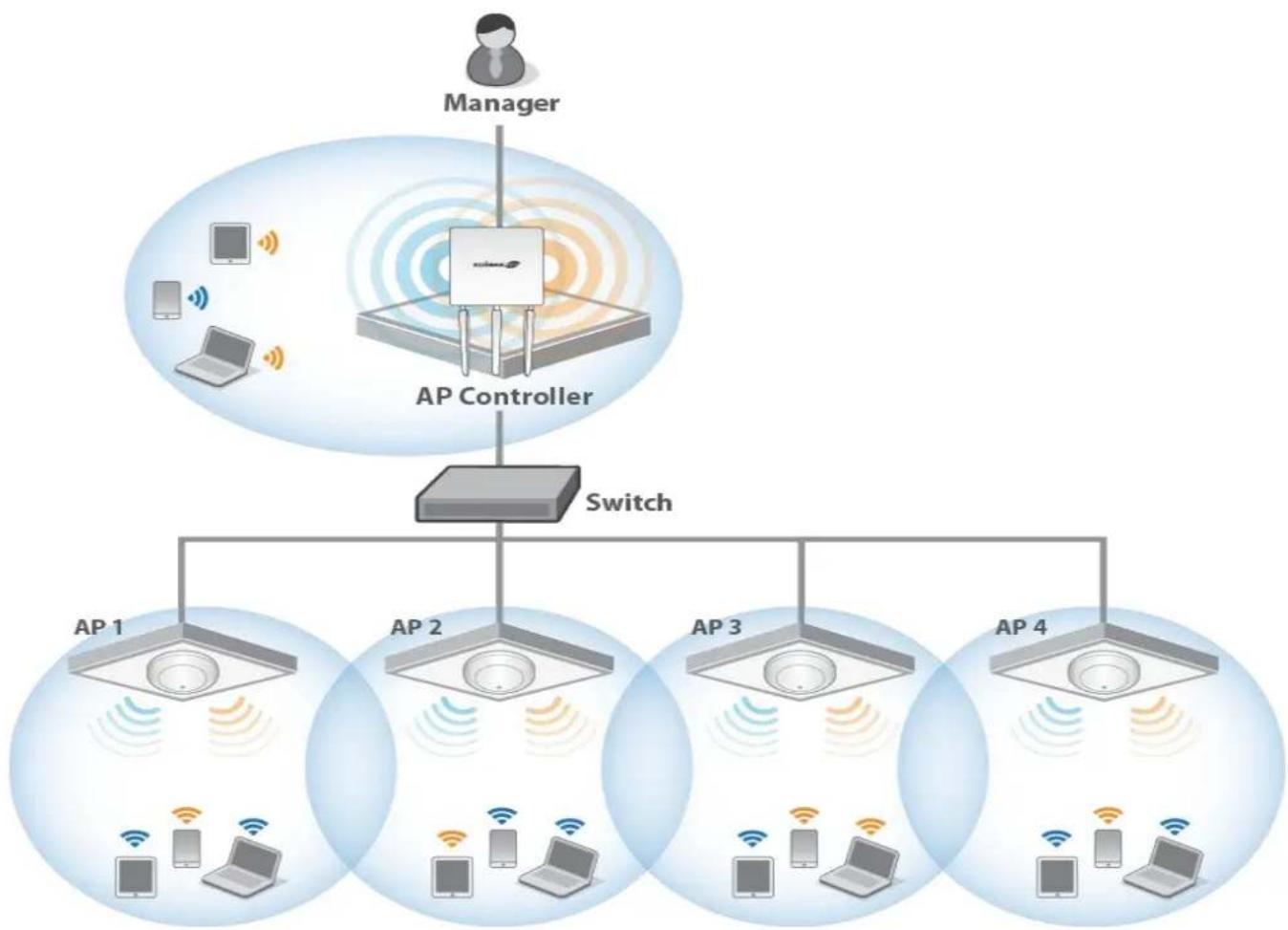
flowchart
graph TD
    A["Manager"] --> B["AP Controller"]
    B --> C["Switch"]
    C --> D1["AP 1"]
    C --> D2["AP 2"]
    C --> D3["AP 3"]
    C --> D4["AP 4"]
    D1 --> E1["Microphones with Wi-Fi"]
    D2 --> E2["Laptops with Wi-Fi"]
    D3 --> E3["Laptops with Wi-Fi"]
    D4 --> E4["Laptops with Wi-Fi"]
    style A fill:#f9f,stroke:#333
    style B fill:#ccf,stroke:#333
    style C fill:#cfc,stroke:#333
    style D1 fill:#ffc,stroke:#333
    style D2 fill:#ffc,stroke:#333
    style D3 fill:#ffc,stroke:#333
    style D4 fill:#ffc,stroke:#333
Edimax Pro NMS is simple to setup. An overview of the system is shown below:
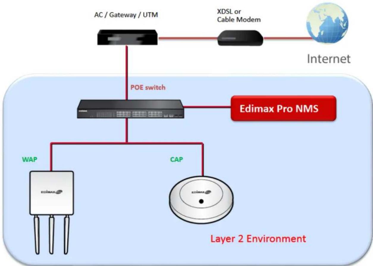
flowchart
graph TD
    A["Internet"] --> B["POE switch"]
    B --> C["EDimax Pro NMS"]
    C --> D["Layer 2 Environment"]
    D --> E["WAP"]
    D --> F["CAP"]
    E --> G["XOIMAX"]
    F --> H["XOIMAX"]
    G --> I["AC / Gateway / UTM"]
    H --> J["XDSL or Cable Modem"]
One AP (access point) is designated as the AP Controller (master) and other connected Edimax Pro APs are automatically designated as Managed APs (slaves). Using Edimax Pro NMS you can monitor, congregate and manage all Managed APs (up to 8) from the single AP Controller.
Follow the steps below:

Ensure you have the latest rmware from the Edimax website for your Edimax Pro products.
- Connect all APs to an Ethernet or PoE switch which is connected to a gateway/router.
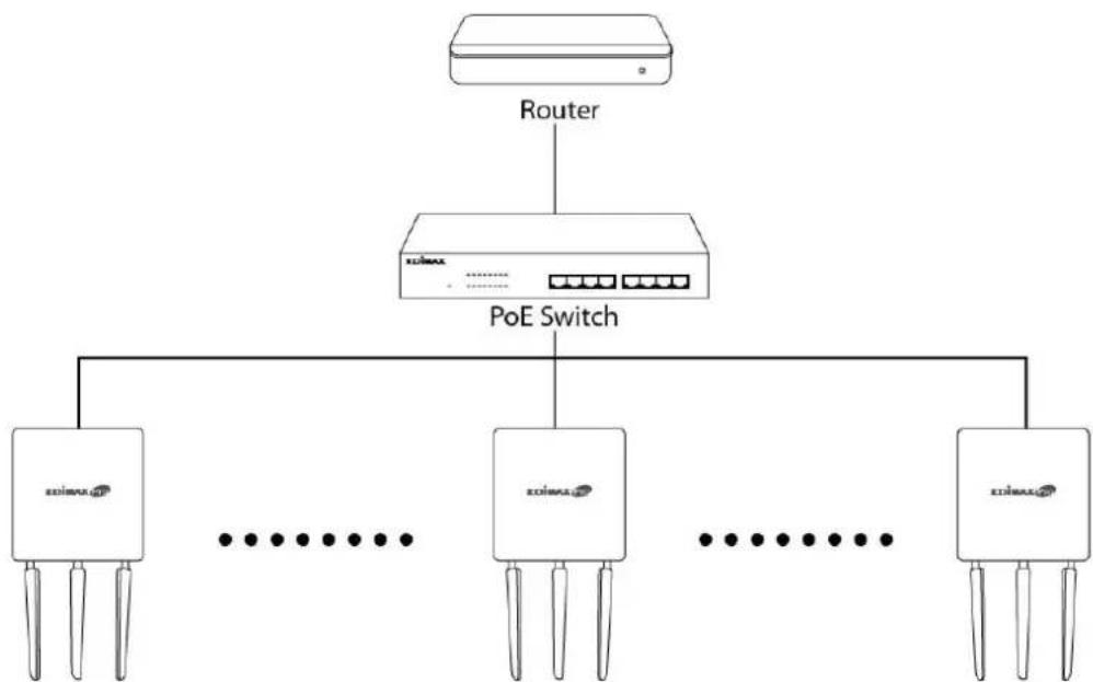
flowchart
graph TD
    A["Router"] --> B["PoE Switch"]
    B --> C["Terminal 1"]
    B --> D["Terminal 2"]
    B --> E["Terminal 3"]
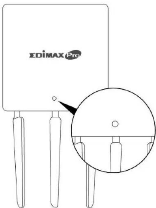
- Ensure all APs are powered on and check LEDs.
- Designate one AP as the AP Controller which will manage all other connected APs (up to 8).
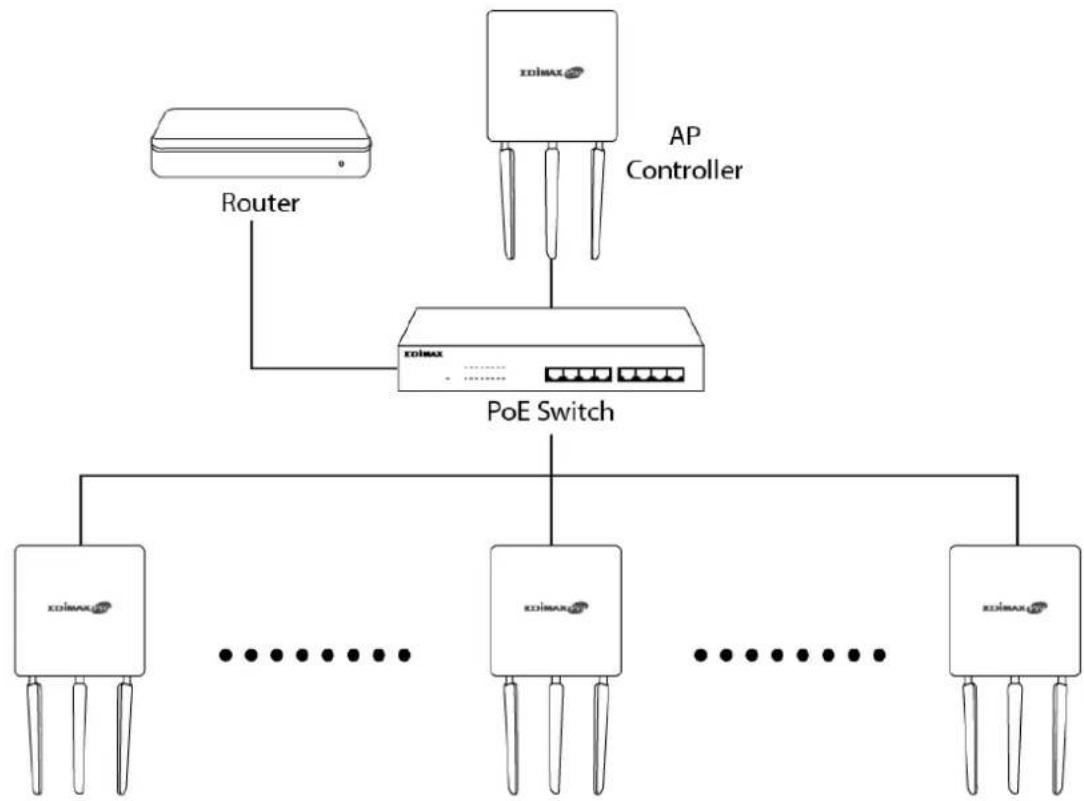
flowchart
graph TD
    A["Router"] --> B["Xolmax"]
    C["AP Controller"] --> B
    B --> D["PoE Switch"]
    D --> E["Xolmax"]
    D --> F["Xolmax"]
    D --> G["Xolmax"]
    E --> H["..."]
    F --> I["..."]
    G --> J["..."]
- Connect a computer to the designated AP Controller using an Ethernet cable.
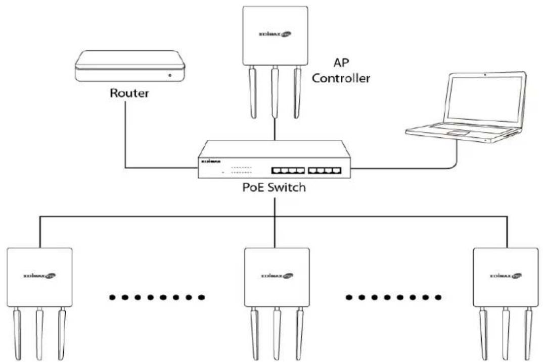
- Open a web browser and enter the AP Controller's IP address in the address eld. The default IP address is 192.168.2.2

Your computer's IP address must be in the same subnet as the AP Controller. Refer to V-1. Conguring your IP Address for help.
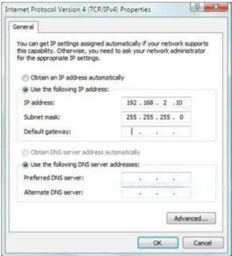

If you changed the AP Controller's IP address, or if your gateway/router uses a DHCP server, ensure you enter the correct IP address. Refer to your gateway/router's sengs.
-
Enter the username & password to login. The default username & password are admin & 1234.
-
You will arrive at the Edimax Pro NMS Dashboard. Go to "Management" → "Operaon Mode" and select "AP Controller Mode" from the drop down menu.
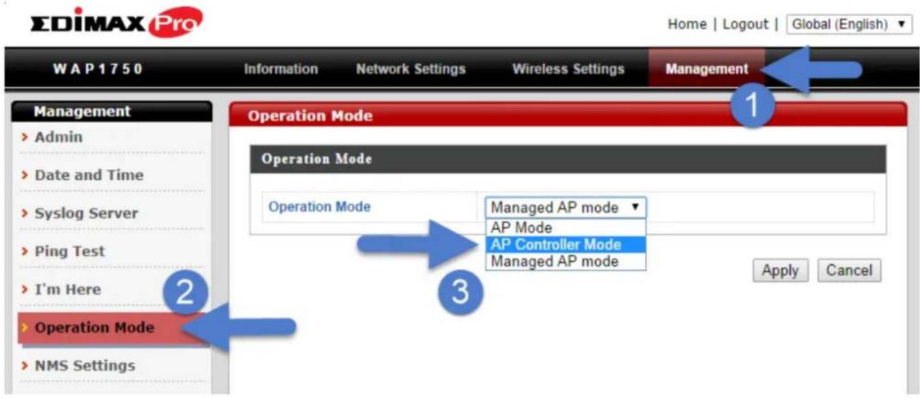
- Click "Apply" to save the sengs.

- Edimax Pro NMS includes a wizard to quickly setup the SSID & security for Managed APs. Click “Wizard” in the top right corner to begin.

- Follow the instructions on-screen to complete Steps 1, 2 & 3 and click "Finish" to save the sengs.
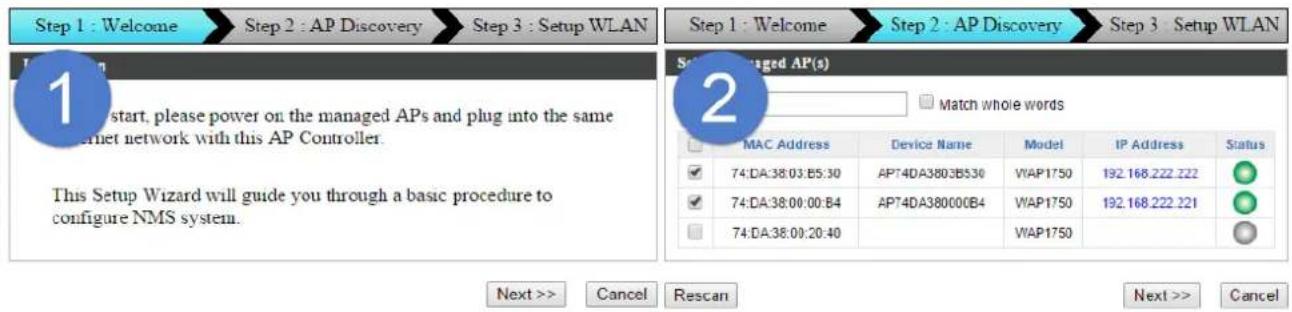
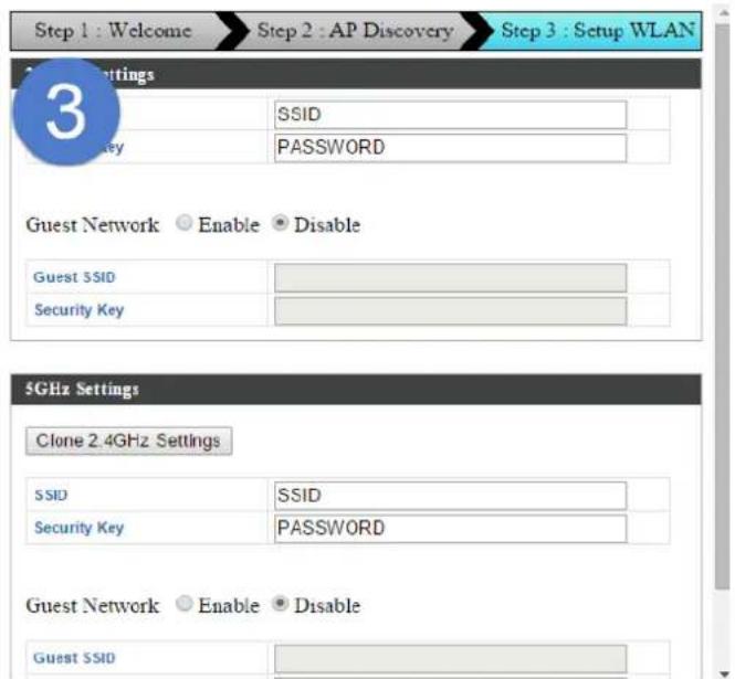

If any of your Managed APs are not found during Step 2 AP Discovery, reset the Managed AP to its factory default sengs. Refer to the Managed AP's user manual for help.
- Your AP Controller & Managed APs should be fully functional. Use the top menu to navigate around Edimax Pro NMS.
EDIMAX Pro

Use Dashboard, Zone Plan, NMS Monitor & NMS Seings to congregate Managed APs.
Use Local Network & Local Sengs to congregate your AP Controller.
The top menu features 7 panels: Dashboard, Zone Plan, NMS Monitor, NMS Sengs, Local Network, Local Sengs & Toolbox.
Dashboard


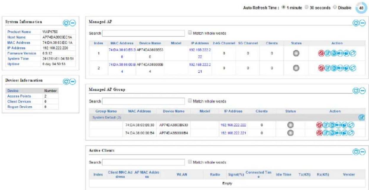
The Dashboard panel displays an overview of your network and key system informaon, with quick links to access conguraon opons for Managed APs and Managed AP groups. Each panel can be refreshed, collapsed or moved according to your preference.
Zone Plan

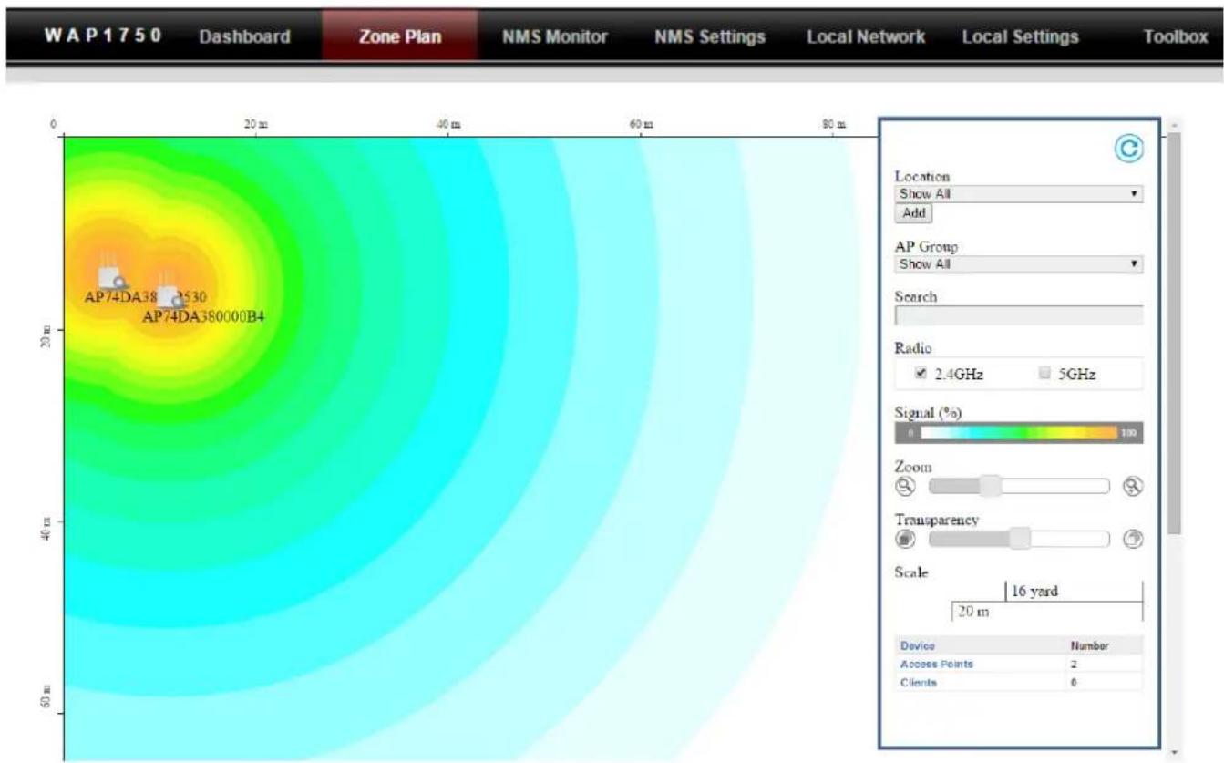
heatmap
| Sensor ID | Location | Show All | Add | | --------------- | ------------ | -------- | --- | | AP74DA38 | AP74DA38 | Yes | No | | AP74DA380000B4 | AP74DA38 | Yes | No |Zone Plan displays a customizable live map of Managed APs for a visual representaon of your network coverage. Each AP icon can be moved around the map, and a background image can be uploaded for user-dened locaon proles using NMS Sengs → Zone Edit. Opons can be congured using the menu on the right side and signal strength is displayed for each AP.
NMS Monitor


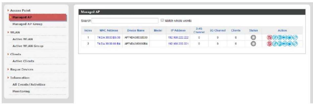
The NMS Monitor panel provides more detailed monitoring informaon about the AP Array than found on the Dashboard, grouped according to categories in the menu down the le side.
NMS Sengs

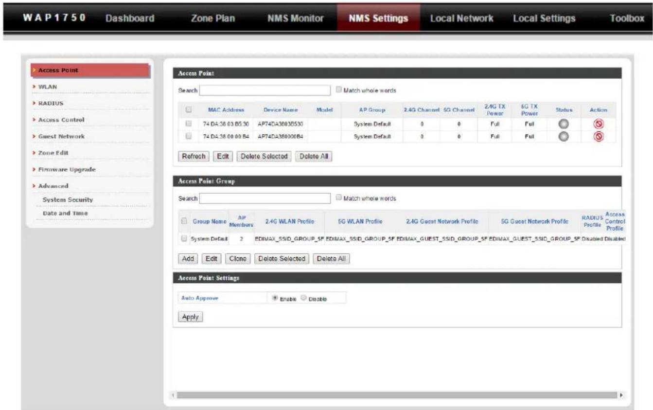
NMS Sengs provides extensive conguraon opons for the AP Array. You can manage each access point, assign access points into groups, manage WLAN, RADIUS & guest network sengs as well as upgrade rmware across mulple access points. The Zone Plan can also be congured using “Zone Edit”.
Local Network

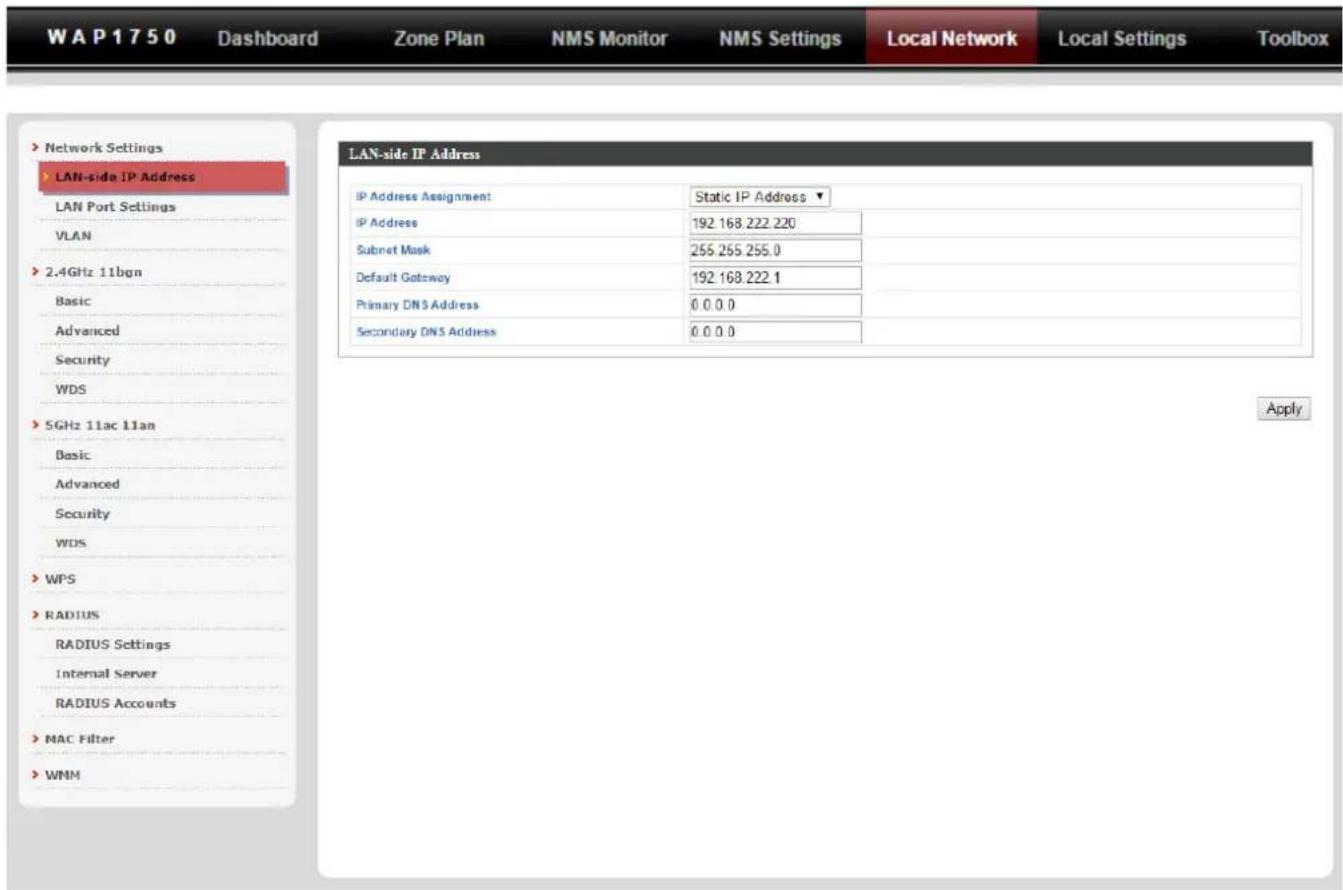
Local Network sengs are for your AP Controller. You can congregate the IP address and DHCP server of the AP Controller in addition to 2.4GHz & 5Ghz Wi-Fi and security, with WPS, RADIUS server, MAC Itering and WMM sengs also available.
Local Sengs
EDIMAX Pro
WAP1750
Dashboard
Zone Plan
NMS Monitor
NMS Settings
Local Network
Local Settings
Toolbox
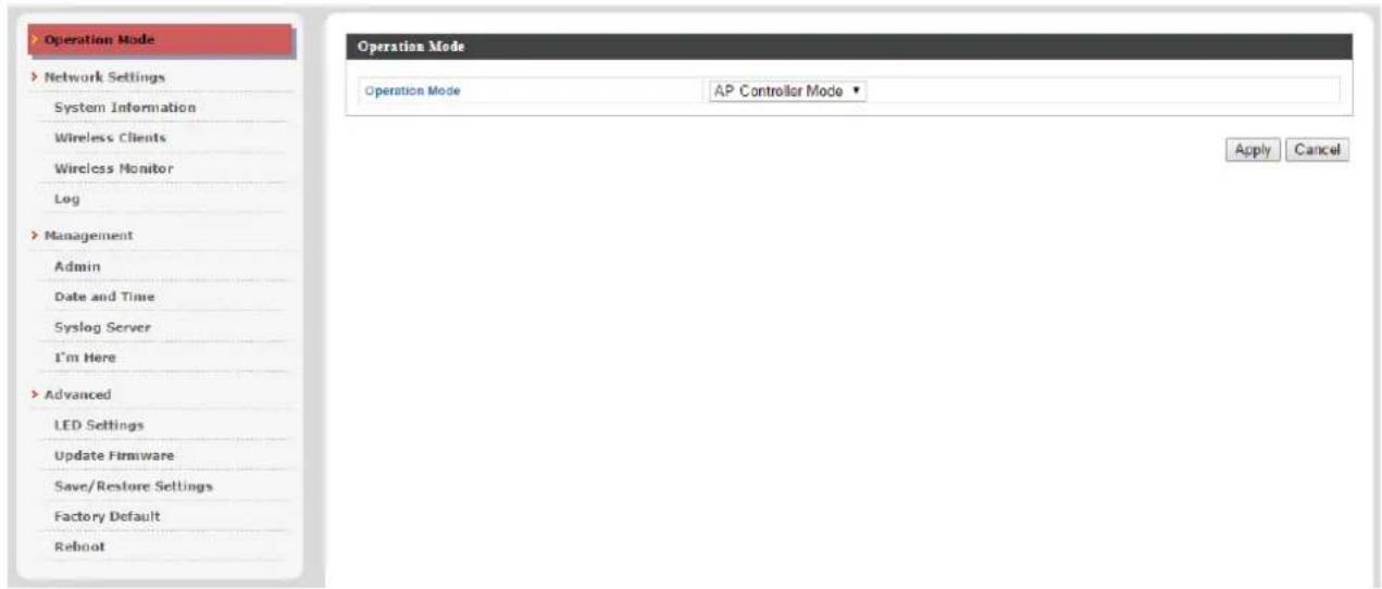
Local Sengs are for your AP Controller. You can set the operaon mode and view network sengs (clients and logs) specifically for the AP Controller, as well as other management sengs such as date/me, admin accounts, rmware and reset.
Toolbox

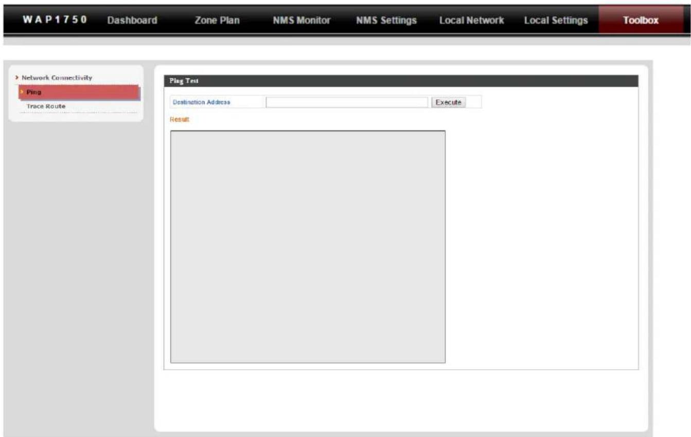
The Toolbox panel provides a network diagnosc tools: ping and traceroute.
Descripons of the funcons of each main panel Dashboard, Zone Plan, NMS Monitor, NMS Sengs, Local Network, Local Sengs & Toolbox can be found below. When using Edimax NMS, click “Apply” to save changes:


Screenshots displayed are examples. The informaon shown on your screen will vary depending on your conguraon.
IV-1. LOGIN, LOGOUT & RESTART

It is recommended that you login to the AP Controller to make conguraons to Managed APs.
LOGIN
- Connect a computer to the designated AP Controller using an Ethernet cable:
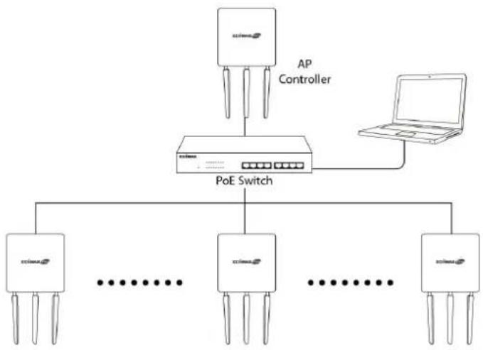
flowchart
graph TD
    A["AP Controller"] --> B["Network Port"]
    B --> C["PoE Switch"]
    C --> D["..."]
    C --> E["..."]
    C --> F["..."]
    C --> G["..."]
    C --> H["..."]
    C --> I["..."]
    C --> J["..."]
    C --> K["..."]
    style A fill:#f9f,stroke:#333
    style B fill:#ccf,stroke:#333
    style C fill:#cfc,stroke:#333
    style D fill:#fcc,stroke:#333
    style E fill:#cff,stroke:#333
    style F fill:#ffc,stroke:#333
    style G fill:#cfc,stroke:#333
    style H fill:#fcc,stroke:#333
    style I fill:#cfc,stroke:#333
    style J fill:#fcc,stroke:#333
    style K fill:#cfc,stroke:#333
    style_L["Router"] --> M["Router"]
    N["Laptop"] --> O["Laptop"]
- Open a web browser and enter the AP Controller's IP address in the address eld. The default IP address is 192.168.2.2


Your computer's IP address must be in the same subnet as the AP Controller. Refer to V-1. Conguring your IP Address for more help.

If you changed the AP Controller's IP address, or if your gateway/router uses a DHCP server, ensure you enter the correct IP address. Refer to your gateway/router's sengs.

If using a DHCP server on the network, it is advised to use your DHCP server's sengs to assign the AP Controller a stac IP address.
- Enter the username & password to login. The default username & password are admin & 1234.
LOGOUT
To logout from Edimax NMS, click "Logout" in the top right corner:

Wizard | Home | Logout |
RESTART
You can restart your AP Controller or any Managed AP using Edimax NMS. To restart your AP Controller go to Local Sengs → Advanced → Reboot and click “Reboot”.
This will reboot the product. Your settings will not be changed. Click "Reboot" to reboot the product now.

To restart Managed APs click the Restart icon for the specied AP on the Dashboard:

IV-2. DASHBOARD
The dashboard displays an overview of your AP array:
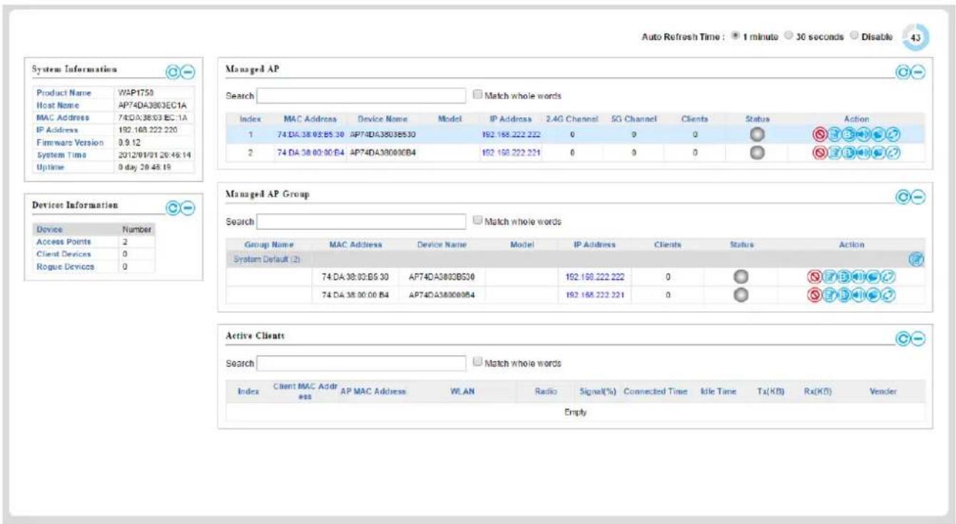

Use the blue icons above to refresh or collapse each panel in the dashboard. Click and drag to move a panel to suit your preference. You can set the dashboard to auto-refresh every 1 minute, 30 seconds or disable auto-refresh:
Auto Refresh Time : ● 1 minute ○ 30 seconds ○ Disable
IV-2-1. System Informaon
System Informaon displays informaon about the AP Controller: Product Name (model), Host Name, MAC Address, IP Address, Firmware Version, System Time and Upme (me the access point has been on).
| Product Name | WAP1750 |
| Host Name | AP74DA3803EC1A |
| MAC Address | 74:DA:38:03:EC:1A |
| IP Address | 192.168.222.220 |
| Firmware Version | 0.9.12 |
| System Time | 2012/01/01 20:49:25 |
| Uptime | 0 day 20:49:31 |
IV-2-2. Devices Informaon
Devices Informaon is a summary of the number of all devices in the local network: Access Points, Clients Connected, and Rogue (unidened) Devices.
| Device | Number |
| Access Points | 2 |
| Client Devices | 0 |
| Rogue Devices | 0 |
IV-2-3. Managed AP
Managed AP displays informaon about each Managed AP in the local network: Index (reference number), MAC Address, Device Name, Model, IP Address, 2.4GHz & 5GHz Wireless Channel Number, No. of Clients connected to each access point, and Status (connected, connecng or disconnected).

The search funcon can be used to locate a specific Managed AP. Type in the search box and the list will update:
Search

Match whole words
The Status icon displays grey (disconnected), yellow (connecng) or green (connected) for each Managed AP.
Each Managed AP has "Acon" icons with the following funcons:

1. Disallow
Remove the Managed AP from the AP array and disable connectivity.
2. Edit
Edit various sengs for the Managed AP (refer to IV-5-1. Access Point).
3. Blink LED
The Managed AP's LED will ash temporarily to help identify & locate access points.
4. Buzzer
The Managed AP's buzzer will sound temporarily to help identify & locate access points.
5. Network Connecvity
Go to the "Network Connecvity" panel to perform a ping or traceroute.
6. Restart
Restarts the Managed AP.
IV-2-4. Managed AP Group
Managed APs can be grouped according to your requirements. Managed AP Group displays informaon about each Managed AP group in the local network: Group Name, MAC Address, Device Name, Model, IP Address, 2.4GHz & 5GHz Wireless Channel Number, No. of Clients connected to each access point, and Status (connected or disconnected).
To edit Managed AP Groups go to NMS Sengs → Access Point (refer to IV-5-1. Access Point).

The search funcon can be used to locate a speci Managed AP Group. Type in the search box and the list will update:
Search


atch whole words
The Status icon displays grey (disconnected), yellow (connecng) or green (connected) for each individual Managed AP.
Each Managed AP has "Acon" icons with the following funcons:

1. Disallow
Remove the Managed AP from the AP array and disable connecvity.
2. Edit
Edit various sengs for the Managed AP (refer to IV-5-1. Access Point)
3. Blink LED
The Managed AP's LED will ash temporarily to help identify & locate access points.
4. Buzzer
The Managed AP's buzzer will sound temporarily to help identify & locate access points.
5. Network Connecvity
Go to the "Network Connecvity" panel to perform a ping or traceroute.
6. Restart
Restarts the Managed AP.
IV-2-5. Acve Clients
Acve Clients displays informaon about each client in the local network: Index (reference number), Client MAC Address, Device Name, Model, IP Address, 2.4GHz & 5GHz Wireless Channel Number, No. of Clients connected to each access point, and Status (on or o).

The search funcon can be used to locate a specific client. Type in the search box and the list will update:

IV-3. ZONE PLAN
The Zone Plan can be fully customized to match your network environment. You can move the AP icons and select dierent locaon images (upload locaon images in NMS Sengs → Zone Edit) to create a visual map of your AP array.
![AP74DA38_C530 AP74DAJ8_C0B4 [AP: 3] 10 m 15 m 20 m 25 m 0 5 m 10 m 15 m 20 m 25 m Location EDIMAX_5F Add Edit AP Group Show All Search Radio 2.4GHz 5GHz Signal (%) Zoom Transparency Scale 4 yard 5 m Device Number Access Points 3 Clients 0](/content/2026/05/979176/images/c07b93dd12a8023f6ee77ad3d47b263065663af2f4560ebefb2cf8923bb0ab7c.jpg)
Use the menu on the right side to make adjustments and mouse-over an AP icon in the zone map to see more informaon. Click an AP icon in the zone map to select it and display acon icons:
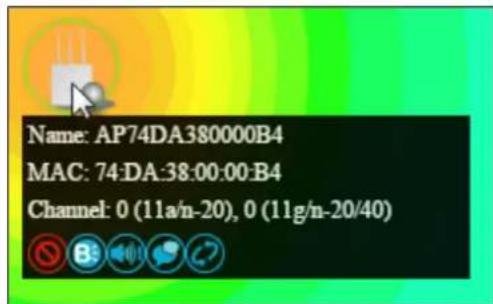
Click and drag an AP icon to move the icon around the zone map. The signal strength for each AP is displayed according to the “Signal” key in the menu on the right side:

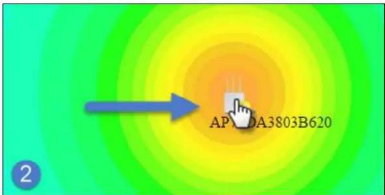
| Locaon | Select a pre-dened locaon from the drop down menu. When you upload a locaon image in NMS Sengs → Zone Edit, it will be available for selecon here. |
| AP Group | You can select an AP Group to display in the zone map. Edit AP Groups in NMS Sengs → Access Point. |
| Search | Use the search box to quickly locate an AP. |
| Radio | Use the checkboxes to display APs according to 2.4GHz or 5GHz wireless radio frequency. |
| Signal | Signal strength key for the signal strength display around each AP in the zone map. |
| Zoom | Use the slider to adjust the zoom level of the map. |
| Transparency | Use the slider to adjust the transparency of locaon images. |
| Scale | Zone map scale. |
| Device/Number | Displays number and type of devices in the zone map. |
IV-4. NMS MONITOR
IV-4-1. Access Point
IV-4-1-1. Managed AP
Displays informaon about each Managed AP in the local network: Index (reference number), MAC Address, Device Name, Model, IP Address, 2.4GHz & 5GHz Wireless Channel Number, No. of Clients connected to each access point, and Status (connected, connecng or disconnected).

The search funcon can be used to locate a specific Managed AP. Type in the search box and the list will update:

The Status icon displays the status of each Managed AP.
| Status Icons | |||
| Icon | Color | Status | Denion |
 | Grey | Disconnected | Managed AP is disconnected. Please check the network conneccon and ensure the Managed AP is in the same IP subnet as the AP Controller. |
 | Red | Authencaon FailedOrIncompatible NMS Version | System security must be the same for all access points in the AP array. Please check security sengs (refer to IV-5-8-1. System Security).Access points must use the same version of Edimax NMS: the managed AP will not be able to make conguraons. Pleaseuse the AP Controller's rmware upgrade funcon (refer to IV-5-7. Firmware Upgrade). |
 | Orange | Conguring or Upgrading | Please wait while the Managed AP makes conguraons or while the rmware is upgrading. |
 | Yellow | Connecng | Please wait while Managed AP is connecng. |
 | Green | Connected | Managed AP is connected. |
 | Blue | Waing for Approval | Managed AP is waing for approval.Refer to IV-5-1. Access Point: Auto Approval. Note: Eight Managed APs are supported. Additional APs will display this status unl an exisng Managed AP is removed. |
Each Managed AP has "Acon" icons with the following funcons:

1. Disallow
Remove the Managed AP from the AP array and disable connectivity.
1. Edit
Edit various sengs for the Managed AP (refer to IV-5-1. Access Point).
2. Blink LED
The Managed AP's LED will ash temporarily to help identify & locate access points.
3. Buzzer
The Managed AP's buzzer will sound temporarily to help identify & locate access points.
4. Network Connecvity
Go to the "Network Connecvity" panel to perform a ping or traceroute.
5. Restart
Restarts the Managed AP.
IV-4-1-2. Managed AP Group
Managed APs can be grouped according to your requirements. Managed AP Group displays informaon about each Managed AP group in the local network: Group Name, MAC Address, Device Name, Model, IP Address, 2.4GHz & 5GHz Wireless Channel Number, No. of Clients connected to each access point, and Status (connected or disconnected).
To edit Managed AP Groups go to NMS Sengs → Access Point (refer to IV-5-1. Access Point).

The search funcon can be used to locate a speci Managed AP Group. Type in the search box and the list will update:

The Status icon displays grey (disconnected), red (authencaon failed/incompatible NMS version), orange (upgrading rmware), yellow (connecng), green (connected) or blue (waing for approval) for each individual Managed AP. Refer to IV-4-1-1. Managed AP: Status Icons for full descripons.
Each Managed AP has "Acon" icons with the following funcons:

2. Disallow
Remove the Managed AP from the AP array and disable connectivity.
3. Edit
Edit various sengs for the Managed AP (refer to IV-5-1. Access Point).
4. Blink LED
The Managed AP's LED will ash temporarily to help identify & locate access points.
5. Buzzer
The Managed AP's buzzer will sound temporarily to help identify & locate access points.
6. Network Connecvity
Go to the "Network Connecvity" panel to perform a ping or traceroute.
7. Restart
Restarts the Managed AP.
IV-4-2. WLAN
IV-4-2-1. Acve WLAN
Displays informaon about each SSID in the AP Array: Index (reference number), Name/SSID, VLAN ID, Authencaon, Encrypon, IP Address and Additional Authencaon.
To congregate encryption and VLANs for Managed APs go to NMS Sengs → WLAN.
The search funcon can be used to locate a specific SSID. Type in the search box and the list will update:

| Index | Name/ESSID | VLAN ID | Authentication | Encryption | Additional Authentication |
| 1 | matt2_4 | 1 | WPA2PSK | WPAPSK | No additional authentication |
| 2 | matt5 | 1 | WPA2PSK | WPAPSK | No additional authentication |
IV-4-2-2. Acve WLAN Group
WLAN groups can be created according to your preference. Acve WLAN Group displays informaon about WLAN group: Group Name, Name/SSID, VLAN ID, Authencaon, Encrypon, IP Address and Additional Authencaon.
The search funcon can be used to locate a specic Acve WLAN Group. Type in the search box and the list will update:

| Active WLAN Group | |||||
| Search Match whole words | |||||
| Group Name | Name/ESSID | VLAN ID | Authentication | Encryption | Additional Authentication |
| Default (0) | |||||
| Empty | |||||
| WLAN Group 2 (1) | |||||
| matt2.4 | 1 | WPA2PSK | AES | No additional authentication | |
| WLAN Group 3 (1) | |||||
| matt5 | 1 | WPA2PSK | AES | No additional authentication | |
IV-4-3. Clients
IV-4-3-1. Acve Clients
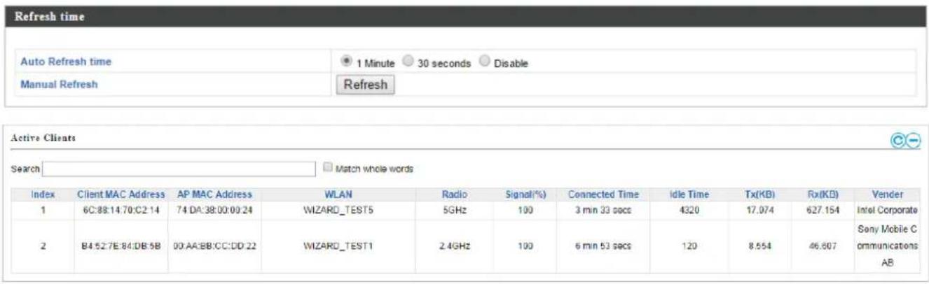
Displays informaon about clients currently connected to the AP Array: Index (reference number), Client MAC Address, AP MAC Address, WLAN (SSID), Radio (2.4GHz or 5GHz), Signal Strength received by Client, Connected Time, Idle Time, Tx & Rx (Data transmied and received by Client in KB), and the Vendor of the client device.
You can set or disable the auto-refresh me for the client list or click "Refresh" to manually refresh.
The search funcon can be used to locate a specific client. Type in the search box and the list will update:

IV-4-4. Rogue Devices
Rogue access point detecon can identify any unauthorized access points which may have been installed in the network.
Click "Start" to scan for rogue devices:

Unknown Rogue Devices displays informaon about rogue devices discovered during the scan: Index (reference number), Channel, SSID, MAC Address, Security, Signal Strength, Type, Vendor and Acon.
The search funcon can be used to locate a known rogue device. Type in the search box and the list will update:




IV-4-5. Informaon
IV-4-5-1. All Events/Acvies
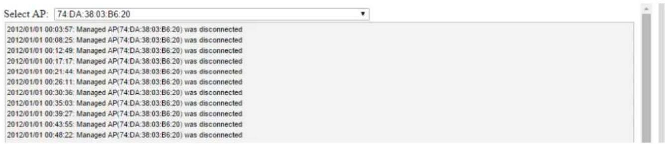
Displays a log of me-stamped events for each access point in the Array – use the drop down menu to select an access point and view the log.
IV-4-5-2. Monitoring
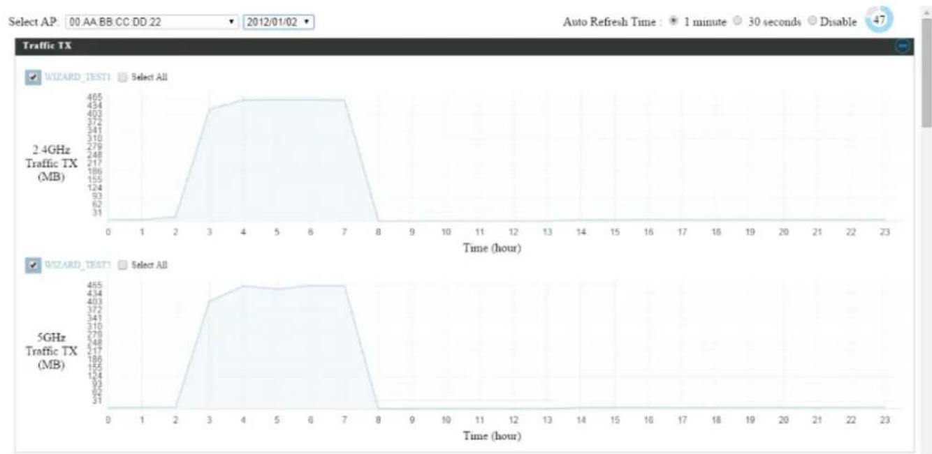
Displays graphical monitoring informaon about access points in the Array for 2.4GHz & 5GHz: Traic Tx (data transmitted in MB), Trac Rx (data received in MB), No. of Clients, Wireless Channel, Tx Power (wireless radio power), CPU Usage and Memory Usage.
Use the drop down menus to select an access point and date.
You can set or disable the auto-refresh me for the data:
Auto Refresh Time : ● 1 minute ○ 30 seconds ○ Disable
area
| Time (hour) | 2.4GHz Traffic TX (MB) | 5GHz Traffic TX (MB) | |-------------|------------------------|----------------------| | 0 | 31 | 31 | | 2 | 465 | 465 | | 3 | 454 | 455 | | 4 | 453 | 454 | | 5 | 452 | 453 | | 6 | 451 | 452 | | 7 | 450 | 451 | | 8 | 31 | 31 |IV-5. NMS Sengs
IV-5-1. Access Point
Displays informaon about each access point and access point group in the local network and allows you to edit access points and edit or add access point groups.
The search funcon can be used to locate an access point or access point group. Type in the search box and the list will update:


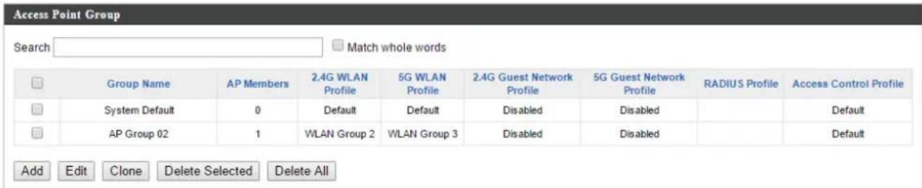

The Status icon displays grey (disconnected), red (authencaon failed/incompatible NMS version), orange (upgrading rmware), yellow (connecng), green (connected) or blue (waing for approval) for each individual Managed AP. Refer to IV-4-1-1. Managed AP: Status Icons for full descripons.
The "Acon" icons enable you to allow or disallow an access point:

Select an access point or access point group using the check-boxes and click "Edit" to make conguraons, or click "Add" to add a new access point group:
The Access Point Sengs panel can enable or disable Auto Approve for all Managed APs. When enabled, Managed APs will automacally join the AP Array with the Controller AP. When disabled, Managed APs must be manually approved to join the AP Array with the Controller AP.

| Access Point Sengs | |
| Auto Approve | Enable or disable Auto Approve for all Managed APs. |
To manually approve a Managed AP, use the allow "Acon" icon for the specied access point:
Edit Access Point
Congure your selected access point on your LAN. You can set the access point as a DHCP client or specify a stac IP address for your access point, and assign the access point to an AP group, as well as edit 2.4GHz & 5GHz wireless radio sengs. An events log is displayed at the boom of the page.
You can also use Prole Sengs to assign the access point to WLAN, Guest Network, RADIUS and Access Control groups independently from Access Point Group sengs.
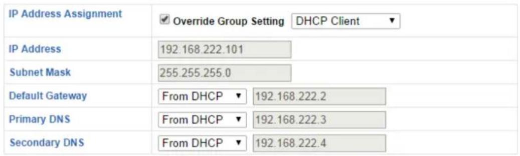
Check the “Override Group Sengs” box to use dierent individual sengs for access points assigned to AP Groups:

Override Group Setting
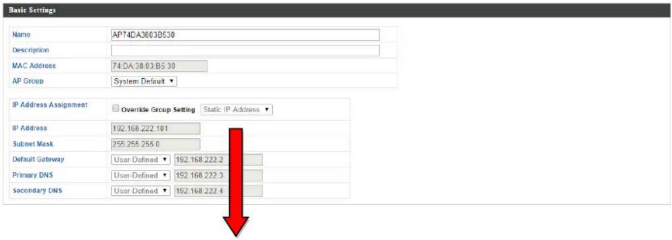
| Basic Sengs | |
| Name | Edit the access point name. The default name is AP + MAC address. |
| Descripon | Enter a descripon of the access point for reference e.g. 2^nd Floor Oce. |
| MAC Address | Displays MAC address. |
| AP Group | Use the drop down menu to assign the AP to an AP Group. You can edit AP Groups from the NMS Sengs → Access Point page. |
| IP Address Assignment | Select “DHCP Client” for your access point to be assigned a dynamic IP address from your router’s DHCP server, or select “Stac IP” to manually specify a stac/xed IP address for your access point (below). Check the box “Override Group Seng” if the AP is a member of an AP Group and you wish to use a dierent seng than the AP Group seng. |
| IP Address | Specify the IP address here. This IP address will be assigned to your access point and will replace the default IP address. |
| Subnet Mask | Specify a subnet mask. The default value is255.255.255.0 |
| Default Gateway | For DHCP users, select “From DHCP” to get default gateway from your DHCP server or “User-Dened” to enter a gateway manually. For stac IP users, the default value is blank. |
| Primary DNS | DHCP users can select “From DHCP” to get primary DNS server’s IP address from DHCP or “User-Dened” to manually enter a value. For stac IP users, the default value is blank. |
| Secondary DNS | DHCP users can select “From DHCP” to get secondary DNS server’s IP address from DHCP or “User-Dened” to manually enter a value. For stac IP users, the default value is blank. |
Radio Settings
| Radio B/G/N (2.4 GHz) | Radio A/N (5.0 GHz) | |||||
| Wireless | Override Group Setting | Enable ▼ | Override Group Setting | Enable ▼ | ||
| Band | Override Group Setting | 11b/g/n ▼ | Override Group Setting | 11a/n/ac ▼ | ||
| Auto Pilot | Override Group Setting | Enable ▼ | Override Group Setting | Enable ▼ | ||
| Auto Pilot Range | Override Group Setting | Ch 1 - 11 ▼ | Override Group Setting | |||
| Auto Pilot Interval | Override Group Setting | Half day ▼ | Override Group Setting | Half day ▼ | ||
| Change channel even if clients are connected | Change channel even if clients are connected | |||||
| Channel Bandwidth | Override Group Setting | Auto ▼ | Override Group Setting | Auto 80/40/20 MHz ▼ | ||
| BSS BasicRateSet | Override Group Setting | all ▼ | Override Group Setting | all ▼ | ||

Advanced Settings
| Radio B/G/N (2.4 GHz) | Radio A/N (5.0 GHz) | |||||
| Contention Slot | Override Group Setting | Short ▼ | Override Group Setting | Short ▼ | ||
| Preamble Type | Override Group Setting | Short ▼ | Override Group Setting | Short ▼ | ||
| Guard Interval | Override Group Setting | Short GI ▼ | Override Group Setting | Short GI ▼ | ||
| 802.11n Protection | Override Group Setting | Enable ▼ | Override Group Setting | Enable ▼ | ||
| DTIM Period | Override Group Setting | 255 | (1-255) | Override Group Setting | 255 | (1-255) |
| RTS Threshold | Override Group Setting | 2347 | (1-2347) | Override Group Setting | 2347 | (1-2347) |
| Fragment Threshold | Override Group Setting | 2346 | (256–2346) | Override Group Setting | 2346 | (256–2346) |
| Multicast Rate | Override Group Setting | Auto ▼ | Override Group Setting | Auto ▼ | ||
| Tx Power | Override Group Setting | 100% ▼ | Override Group Setting | 100% ▼ | ||
| Beacon Interval | Override Group Setting | 100 | (40-1000 ms) | Override Group Setting | 100 | (40-1000 ms) |
| Station idle timeout | Override Group Setting | 300 | (30-65535 seconds) | Override Group Setting | 300 | (30-65535 seconds) |
| Radio Sengs | |
| Wireless | Enable or disable the access point’s 2.4GHz or 5GHz wireless radio. When disabled, no SSIDs on that frequency will be acve. |
| Band | Select the wireless standard used for the access point. Combinaons of 802.11b,802.11g, 802.11n & 802.11ac can be selected. |
| Auto Pilot | Enable/disable auto channel selecon. Auto channel selecon will automacally set the wireless channel for the access point's 2.4GHz or 5GHz frequency based on availability and potenal interference. When disabled, select a channel manually. |
| Auto Pilot Range | Select a range from which the auto channel seng (above) will choose a channel. |
| Auto Pilot Interval | Specify a frequency for how oen the auto channel seng will check/reassign the wireless channel. Check/uncheck the “Change channel even if clients are connected” box according to your preference. |
| Channel Bandwidth | Set the channel bandwidth or use Auto (automacally select based on interference level). |
| BSS BasicRateSet | Set a Basic Service Set (BSS) rate: this is a series of rates to control communicaon frames for wireless clients. |
These sengs are for experienced users only. Please do not change any of the values on this page unless you are already familiar with these funcons.

Changing these sengs can adversely act the performance of your access point.
| Advanced Sengs | |
| Contenon Slot | Select “Short” or “Long” – this value is used for contenon windows in WMM (see IV-6-7. WMM). |
| Preamble Type | Set the wireless radio preamble type. The preamble type in 802.11 based wireless communicaon denes the length of the CRC (Cyclic Redundancy Check) block for communicaon between the access point and roaming wireless adapters. The default value is “Short Preamble”. |
| Guard Interval | Set the guard interval. A shorter interval can improve performance. |
| 802.11g Protecon | Enable/disable 802.11g protecon, which increases reliability but reduces bandwidth (clients will send Request to Send (RTS) to access point, and access point will broadcast Clear to Send (CTS), before a packet is sent from client.) |
| 802.11n Protecon | Enable/disable 802.11n protecon, which increases reliability but reduces bandwidth (clients will send Request to Send (RTS) to access point, and access point will broadcast Clear to Send (CTS), before a packet is sent from client.) |
| DTIM Period | Set the DTIM (delivery trac indicaon message) period value of the wireless radio. The default value is 1. |
| RTS Threshold | Set the RTS threshold of the wireless radio. The default value is 2347. |
| Fragment Threshold | Set the fragment threshold of the wireless radio. The default value is 2346. |
| Mulcast Rate | Set the transfer rate for mulcast packets or use the “Auto” seng. |
| Tx Power | Set the power output of the wireless radio. You may not require 100% output power. Seng a lower power output can enhance security since potenally malicious/unknown users in distant areas will not be able to access your signal. |
| Beacon Interval | Set the beacon interval of the wireless radio. The default value is 100. |
| Staon idle meout | Set the interval for keepalive messages from the access point to a wireless client to verify if the staon is sll alive/acve. |

Prole Sengs
| WLAN Group | Assign the access point's 2.4GHz or 5GHz SSID(s) to a WLAN Group. You can edit WLAN groups in NMS Sengs → WLAN. |
| Guest Network Group | Assign the access point's 2.4GHz or 5GHz SSID(s) to a Guest Network Group. You can edit Guest Network groups in NMS Sengs → Guest Network. |
| RADIUS Group | Assign the access point's 2.4GHz SSID(s) to a RADIUS group. You can edit RADIUS groups in NMS Sengs → RADIUS. |
| Access Control Group | Assign the access point's 2.4GHz SSID(s) to a RADIUS group. You can edit RADIUS groups in NMS Sengs → Access Control |
Add/Edit Access Point Group
Congure your selected access point group. Access point group sengs apply to all access points in the group, unless individually set to override group sengs.
You can use Prole Group Sengs to assign the access point group to WLAN, Guest Network, RADIUS and Access Control groups.
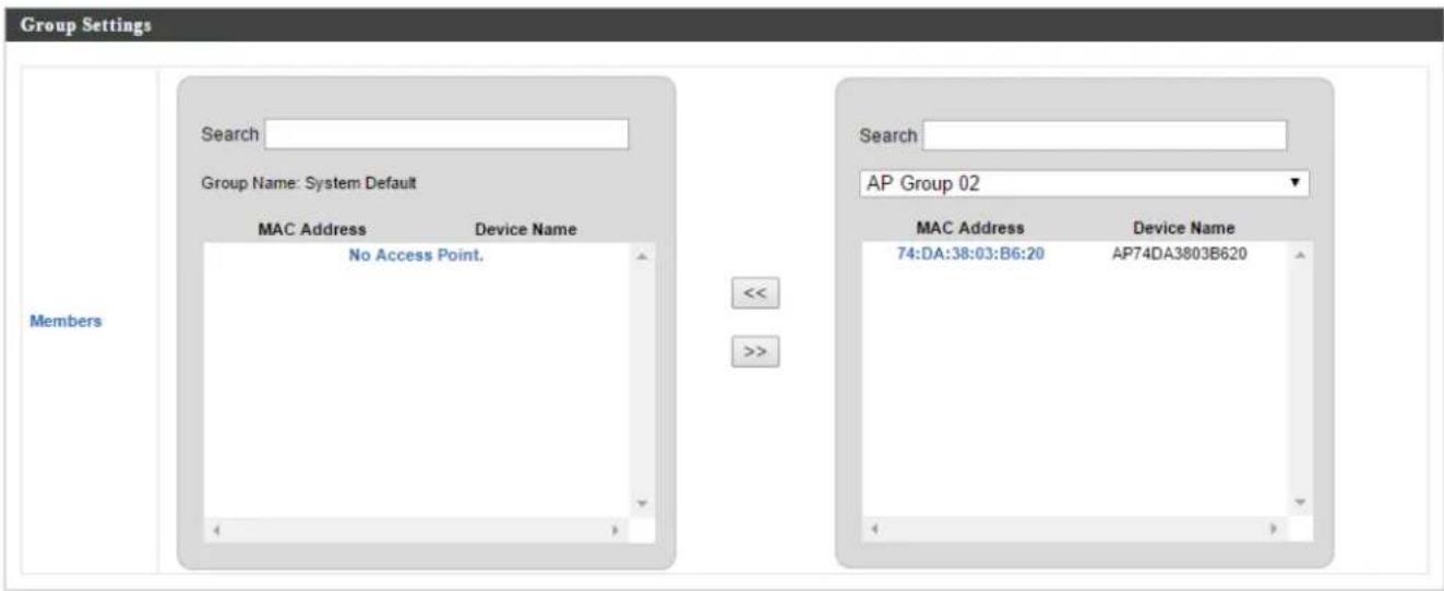
The Group Sengs panel can be used to quickly move access points between existing groups: select an access point and use the drop down menu or search to select access point groups and use << and >> arrows to move APs between groups.

| Basic Group Sengs | |
| Name | Edit the access point group name. |
| Descripon | Enter a descripon of the access point group for reference e.g. 2^nd Floor Oce Group. |
| Radio B/G/N (2.4 GHz) | Radio A/N (5.0 GHz) | |||
| Wireless | Enable | ✓ | Enable | ✓ |
| Band | 11b/g/n | ✓ | 11a/n/ac | ✓ |
| Auto Pilot | Enable | ✓ | Enable | ✓ |
| Auto Pilot Range | Ch 1 - 11 | ✓ | ✓ | |
| Auto Pilot Interval | Half day | ✓ | Half day | ✓ |
| Change channel even if clients are connected | Change channel even if clients are connected | |||
| Channel Bandwidth | Auto | ✓ | Auto 80/40/20 MHz | ✓ |
| BSS BasicRateSet | all | ✓ | all | ✓ |
| Advanced Settings | ||||
| Radio B/G/N (2.4 GHz) | Radio A/N (5.0 GHz) | |||
| Contention Slot | Short | ✓ | Short | ✓ |
| Preamble Type | Short | ✓ | Short | ✓ |
| Guard Interval | Short GI | ✓ | Short GI | ✓ |
| 802.11n Protection | Enable | ✓ | Enable | ✓ |
| DTIM Period | 255 | (1-255) | 255 | (1-255) |
| RTS Threshold | 2347 | (1-2347) | 2347 | (1-2347) |
| Fragment Threshold | 2346 | (256-2346) | 2346 | (256-2346) |
| Multicast Rate | Auto | ✓ | Auto | ✓ |
| Tx Power | 100% | ✓ | 100% | ✓ |
| Beacon Interval | 100 | (40-1000 ms) | 100 | (40-1000 ms) |
| Station idle timeout | 300 | (30-65535 seconds) | 300 | (30-65535 seconds) |
| Radio Group Sengs | |
| Wireless | Enable or disable the access point group's 2.4GHz or 5GHz wireless radio. When disabled, no SSIDs on that frequency will be acve. |
| Band | Select the wireless standard used for the access point group. Combinaons of 802.11b, 802.11g, 802.11n & 802.11ac can be selected. |
| Auto Pilot | Enable/disable auto channel selecon. Auto channel selecon will automacally set the wireless channel for the access point group's 2.4GHz or 5GHz frequency based on availability and potenal interference. When disabled, select a channel manually. |
| Auto Pilot Range | Select a range from which the auto channel seng (above) will choose a channel. |
| Auto Pilot Interval | Specify a frequency for how oen the auto channel seng will check/reassign the wireless channel. Check/unchecked the “Change channel even if clients are connected” box according to your preference. |
| Channel Bandwidth | Set the channel bandwidth or use Auto (automacally select based on interference level). |
| BSS BasicRateSet | Set a Basic Service Set (BSS) rate: this is a series of rates to control communicaon frames for wireless clients. |
These sengs are for experienced users only. Please do not change any of the values on this page unless you are already familiar with these funcons.

Changing these sengs can adversely act the performance of your access points.
| Advanced Sengs | |
| Contenon Slot | Select “Short” or “Long” – this value is used for contenon windows in WMM (see IV-6-7. WMM). |
| Preamble Type | Set the wireless radio preamble type. The preamble type in 802.11 based wireless communicaon denes the length of the CRC (Cyclic Redundancy Check) block for communicaon between the access point and roaming wireless adapters. The default value is “Short Preamble”. |
| Guard Interval | Set the guard interval. A shorter interval can improve performance. |
| 802.11g Protecon | Enable/disable 802.11g protecon, which increases reliability but reduces bandwidth (clients will send Request to Send (RTS) to access point, and access point will broadcast Clear to Send (CTS), before a packet is sent from client.) |
| 802.11n Protecon | Enable/disable 802.11n protecon, which increases reliability but reduces bandwidth (clients will send Request to Send (RTS) to access point, and access point will broadcast Clear to Send (CTS), before a packet is sent from client.) |
| DTIM Period | Set the DTIM (delivery trac indicaon message) period value of the wireless radio. The default value is 1. |
| RTS Threshold | Set the RTS threshold of the wireless radio. The default value is 2347. |
| Fragment Threshold | Set the fragment threshold of the wireless radio. The default value is 2346. |
| Mulcast Rate | Set the transfer rate for mulcast packets or use the “Auto” seng. |
| Tx Power | Set the power output of the wireless radio. You may not require 100% output power. Seng a lower power output can enhance security since potenally malicious/unknown users in distant areas will not be able to access your signal. |
| Beacon Interval | Set the beacon interval of the wireless radio. The default value is 100. |
| Staon idle meout | Set the interval for keepalive messages from the access point to a wireless client to verify if the staon is sll alive/acve. |

| Prole Group Sengs | |
| WLAN Group | Assign the access point group's 2.4GHz or 5GHz SSIDs to a WLAN Group. You can edit WLAN groups in NMS Sengs → WLAN. |
| Guest Network Group | Assign the access point group's 2.4GHz or 5GHz SSIDs to a Guest Network Group. You can edit Guest Network groups in NMS Sengs → Guest Network. |
| RADIUS Group | Assign the access point group's 2.4GHz SSIDs to a RADIUS group. You can edit RADIUS groups in NMS Sengs → RADIUS. |
| Access Control Group | Assign the access point's 2.4GHz SSIDs to a RADIUS group. You can edit RADIUS groups in NMS Sengs → Access Control. |
IV-5-2. WLAN
Displays informaon about each WLAN and WLAN group in the local network and allows you to add or edit WLANs & WLAN Groups. When you add a WLAN Group, it will be available for selecon in NMS Sengs → Access Point access point Prole Sengs & access point group Prole Group Sengs (IV-5-1.)
The search funcon can be used to locate a WLAN or WLAN Group. Type in the search box and the list will update:


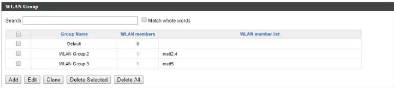
Select a WLAN or WLAN Group using the check-boxes and click "Edit" or click "Add" to add a new WLAN or WLAN Group:
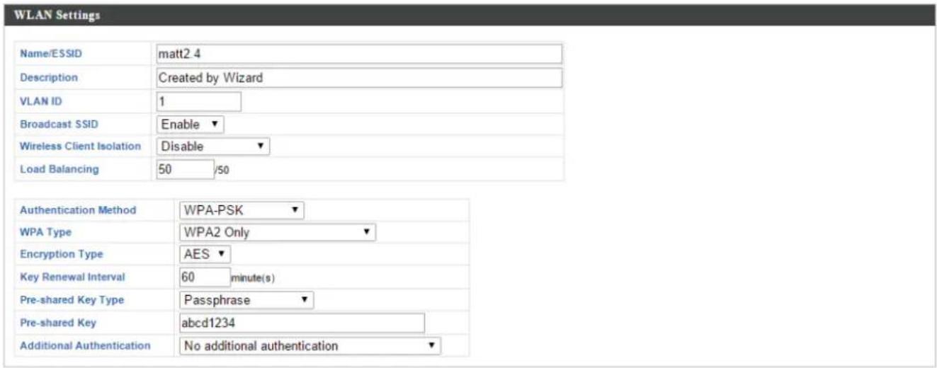

| WLAN Sengs | |
| Name/ESSID | Edit the WLAN name (SSID). |
| Descripon | Enter a descripon of the SSID for reference e.g. 2^nd Floor Oce HR. |
| SSID | Select which SSID to congregate security sengs for. |
| VLAN ID | Specify the VLAN ID. |
| Broadcast SSID | Enable or disable SSID broadcast. When enabled, the SSID will be visible to clients as an available Wi-Fi network. When disabled, the SSID will not be visible as an available Wi-Fi network to clients – clients must manually enter the SSID in order to connect. A hidden (disabled) SSID is typically more secure than a visible (enabled) SSID. |
| Wireless Client Isolaon | Enable or disable wireless client isolaon. Wireless client isolaon prevents clients connected to the access point from communicating with each other and improves security. Typically, this funcon is useful for corporate environments or public hot spotsand can prevent brute force aacks on clients' usernames and passwords. |
| Load Balancing | Load balancing limits the number of wireless clients connected to an SSID. Set a load balancing value (maximum 50). |
| Authencaon Method | Select an authencaon method from the drop down menu. |
| Additional Authencaon | Select an additional authencaon method from the drop down menu. |
Various security opons (wireless data encrypon) are available. When data is encrypted, informaon transmied wirelessly cannot be read by anyone who does not know the correct encrypon key.

It's essenal to congregate wireless security in order to prevent unauthorised access to your network.

Select hard-to-guess passwords which include combinaons of numbers, leers and symbols, and change your password regularly.
Please refer to IV-6-2-3.Security for more informaon on authencaon and additional authencaon types.
| WLAN Advanced Sengs | |
| Smart Handover | Enable or disable Smart Handover. |
| RSSI Threshold | Set a RSSI Threshold level. |
Add/Edit WLAN Group
When you add a WLAN Group, it will be available for selecon in NMS Sengs → Access Point access point Prole Sengs & access point group Prole Group Sengs (IV-5-1.)
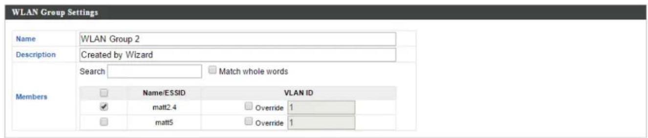
| WLAN Group Sengs | |
| Name | Edit the WLAN Group name. |
| Descripon | Enter a descripon of the WLAN Group for reference e.g. 2^nd Floor Oce HR Group. |
| Members | Select SSIDs to include in the group using the checkboxes and assign VLAN IDs. |
IV-5-3. RADIUS
Displays informaon about External & Internal RADIUS Servers, Accounts and Groups and allows you to add or edit RADIUS Servers, Accounts & Groups. When you add a RADIUS Group, it will be available for selecon in NMS Sengs → Access Point access point Prole Sengs & access point group Prole Group Sengs (IV-5-1.)
The search funcon can be used to locate a RADIUS Server, Account or Group. Type in the search box and the list will update:
Search


match whole words
Make a selecon using the check-boxes and click "Edit" or click "Add" to add a new WLAN or WLAN Group:

Edit

Add




Add/Edit External RADIUS Server
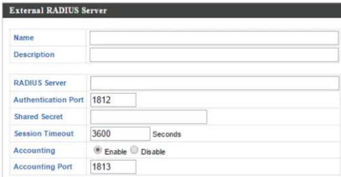
| Name | Enter a name for the RADIUS Server. |
| Descripon | Enter a descripon of the RADIUS Server for reference. |
| RADIUS Server | Enter the RADIUS server host IP address. |
| Authencaon Port | Set the UDP port used in the authencaon protocol of the RADIUS server. Value must be between 1 – 65535. |
| Shared Secret | Enter a shared secret/password between 1 – 99 characters in length. This should match the “MAC-RADIUS” password used in IV-3-1-3-6 or IV-3-2-3. |
| Session Timeout | Set a duraon of session meout in seconds between 0 – 86400. |
| Accounting | Enable or disable RADIUS accoung. |
| Accounting Port | When accoung is enabled (above), set the UDP port used in the accoung protocol of the RADIUS server. Value must be between 1 – 65535. |
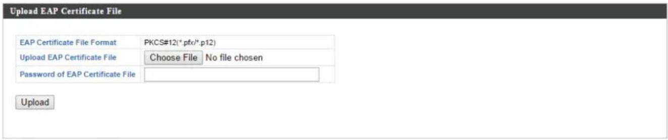
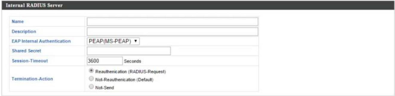
Add/Edit Internal RADIUS Server
| Upload EAP Cercate File | |
| EAP Cercate File Format | Displays the EAP cercate le format: PCK#12(*.pfx/*.p12) |
| EAP Cercate File | Click “Upload” to open a new window and select the locaon of an EAP cercate le to use. If no cercate le is uploaded, the internal RADIUS server will use a self-made cercate. |
| Internal RADIUS Server | |
| Name | Enter a name for the Internal RADIUS Server. |
| Descripon | Enter a descripon of the Internal RADIUS Server for reference. |
| EAP Cercate File Format | Displays the EAP cercate le format: PCK#12(*.pfx/*.p12) |
| EAP Cercate File | Click “Upload” to open a new window and select the locaon of an EAP cercate le to use. If no cercate le is uploaded, the internal RADIUS server will use a self-made cercate. |
| EAP Internal Authencaon | Select EAP internal authencaon type from the drop down menu. |
| Shared Secret | Enter a shared secret/password for use between the internal RADIUS server and RADIUS client. The shared secret should be 1 – 99 characters in length. |
| Session Timeout | Set a duraon of session meout in seconds between 0 – 86400. |
| Terminaon Acon | Select a terminaon-acon aribute: “Reauthencaon” sends a RADIUS request to the access point, “Not-Reathencaon” sends a default terminaon-acon aribute to the access point, “Not-Send” no terminaon-acon aribute is sent to the access point. |
Add/Edit RADIUS Accounts
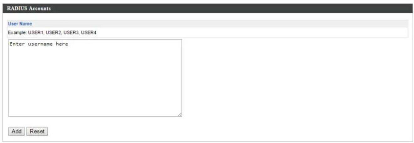
The internal RADIUS server can authenticate up to 256 user accounts. The "RADIUS Accounts" page allows you to congregate and manage users.
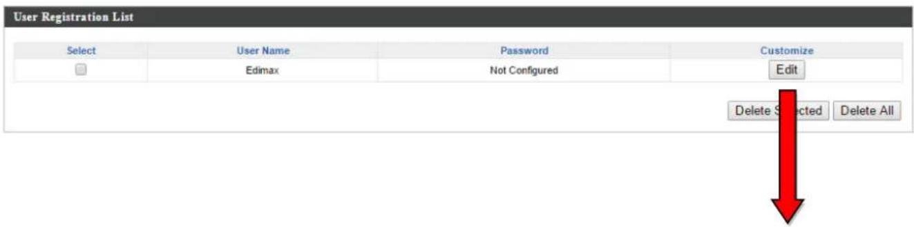
| Edit User Registration List | |
| User Name | Edimax(4-16characters) |
| Password | |
| RADIUS Accounts | |
| User Name | Enter the user names here, separated by commas. |
| Add | Click “Add” to add the user to the user registraon list. |
| Reset | Clear text from the user name box. |
| User Registraon List | |
| Select | Check the box to select a user. |
| User Name | Displays the user name. |
| Password | Displays if specied user name has a password (congured) or not (not congured). |
| Customize | Click “Edit” to open a new eld to set/edit a password for the specied user name (below). |
| Delete Selected | Delete selected user from the user registraon list. |
| Delete All | Delete all users from the user registraon list. |
| Edit User Registraon List | |
| User Name | Exisng user name is displayed here and can be edited according to your preference. |
| Password | Enter or edit a password for the specied user. |
Add/Edit RADIUS Group
When you add a RADIUS Group, it will be available for selecon in NMS Sengs → Access Point access point Prole Sengs & access point group Prole Group Sengs (IV-5-1.)
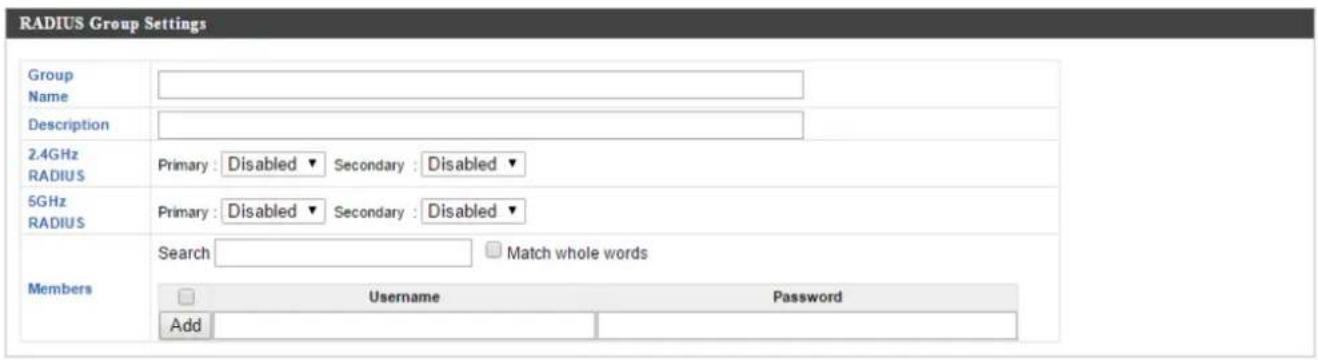
| RADIUS Group Sengs | |
| Group Name | Edit the RADIUS Group name. |
| Descripon | Enter a descripon of the RADIUS Group for reference. |
| 2.4GHz RADIUS | Enable/Disable primary & secondary RADIUS servers for 2.4GHz. |
| 5GHz RADIUS | Enable/Disable primary & secondary RADIUS servers for 5GHz. |
| Members | Add RADIUS user accounts to the RADIUS group. |
IV-5-4. Access Control
MAC Access Control is a security feature that can help to prevent unauthorized users from connecng to your access point.
This funcon allows you to dene a list of network devices permied to connect to the access point. Devices are each idened by their unique MAC address. If a device which is not on the list of permied MAC addresses aempts to connect to the access point, it will be denied.
The Access Control panel displays informaon about MAC Access Control & MAC Access Control Groups and Groups and allows you to add or edit MAC Access Control & MAC Access Control Group sengs. When you add an Access Control Group, it will be available for selecon in NMS Sengs → Access Point access point Prole Seings & access point group Prole Group Sengs (IV-5-1.)
The search funcon can be used to locate a MAC address or MAC Access Control Group. Type in the search box and the list will update:

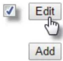
Make a selecon using the check-boxes and click "Edit" or click "Add" to add a new MAC Address or MAC Access Control Group:


Add/Edit MAC Access Control
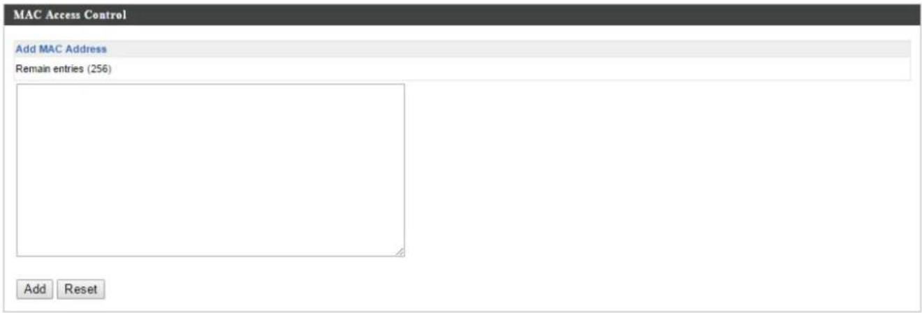

| Add MAC Address | Enter a MAC address of computer or network device manually e.g. ‘aa-bb-cc-dd-ee-ff’ or enter mulple MAC addresses separated with commas, e.g.‘aa-bb-cc-dd-ee-,aa-bb-cc-dd-ee-gg’ |
| Add | Click “Add” to add the MAC address to the MAC address ltering table. |
| Reset | Clear all elds. |
MAC address entries will be listed in the “MAC Address Filtering Table”. Select an entry using the “Select” checkbox.
| Select | Delete selected or all entries from the table. |
| MAC Address | The MAC address is listed here. |
| Delete Selected | Delete the selected MAC address from the list. |
| Delete All | Delete all entries from the MAC addressItering table. |
| Export | Click “Export” to save a copy of the MACItering table. A new window will pop up for you to select a locaon to save the le. |
Add/Edit MAC Access Control Group
When you add an Access Control Group, it will be available for selecon in NMS Sengs → Access Point access point Prole Sengs & access point group Prole Group Sengs (IV-5-1.)
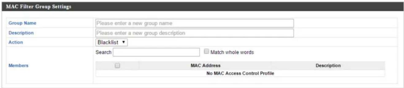
| MAC Filter Group Sengs | |
| Group Name | Edit the MAC Access Control Group name. |
| Descripon | Enter a descripon of the MAC Access Control Group for reference. |
| Acon | Select “Blacklist” to deny access to specied MAC addresses in the group, and select “Whitelist” to permit access to specied MAC address in the group. |
| Members | Add MAC addresses to the group. |
IV-5-5. Guest Network
You can setup an additional “Guest” Wi-Fi network so guest users can enjoy Wi-Fi connecvity without accessing your primary networks. The “Guest” screen displays sengs for your guest Wi-Fi network.
The Guest Network panel displays informaon about Guest Networks and Guest Network Groups and allows you to add or edit Guest Network and Guest Network Group sengs. When you add a Guest Network Group, it will be available for selecon in NMS Sengs → Access Point access point Prole Sengs & access point group Prole Group Sengs (IV-5-1.)
The search funcon can be used to locate a Guest Network or Guest Network Group. Type in the search box and the list will update:

Make a selecon using the check-boxes and click "Edit" or click "Add" to add a new Guest Network or Guest Network Group.


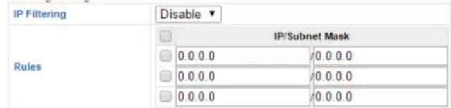
Guest Access Policy

Filtering Settings
| Guest Network Sengs | |
| Name/ESSID | Edit the Guest Network name (SSID). |
| Descripon | Enter a descripon of the Guest Network for reference e.g. 2^nd Floor Oce HR. |
| VLAN ID | Specify the VLAN ID. |
| Broadcast SSID | Enable or disable SSID broadcast. When enabled, the SSID will be visible to clients as an available Wi-Fi network. When disabled, the SSID will not be visible as an available Wi-Fi network to clients – clients must manually enter the SSID in order to connect. A hidden (disabled) SSID is typically more secure than a visible (enabled) SSID. |
| Wireless Client Isolaon | Enable or disable wireless client isolaon. Wireless client isolaon prevents clients connected to the access point from communicang with each other and improves security. Typically, this funcon is useful for corporate environments or public hot spots and can prevent brute force aacks onclients' usernames and passwords. |
| Load Balancing | Load balancing limits the number of wireless clients connected to an SSID. Set a load balancing value (maximum 50). |
| WMM | Enable or disable WMM (Wi-Fi Mulmedia) trac priorizing. |
| Authencaon Method | Select an authencaon method from the drop down menu. |
| Additional Authencaon | Select an additional authencaon method from the drop down menu. |
Various security opons (wireless data encrypon) are available. When data is encrypted, informaon transmied wirelessly cannot be read by anyone who does not know the correct encrypon key.

It's essenal to congregate wireless security in order to prevent unauthorised access to your network.

Select hard-to-guess passwords which include combinaons of numbers, leers and symbols, and change your password regularly.
Please refer to IV-6-2-3.Security for more informaon on authentication and additional authencaon types.
| Guest Access Policy | |
| Trac Shaping | Enable or disable trac shaping for the guest network. |
| Downlink | Enter a downlink limit in MB. |
| Uplink | Enter an uplink limit in MB. |
| IP Filtering | Select “Deny” or “Allow” to deny or allow specied IP addresses to access the guest network. Select “Disable” to disable IP Itering. |
| Rules | Enter IP addresses to be Itered according to the Deny or Allow rule specied above and check the box for each IP address to be Itered. |
Add/Edit Guest Network Group
When you add a Guest Network Group, it will be available for selecon in NMS Sengs → Access Point access point Prole Sengs & access point group Prole Group Sengs (IV-5-1.)

| Guest Network Group Sengs | |
| Group Name | Edit the Guest Network Group name. |
| Descripon | Enter a descripon of the Guest Network for reference. |
| Members | Add SSIDs to the Guest Network group. |
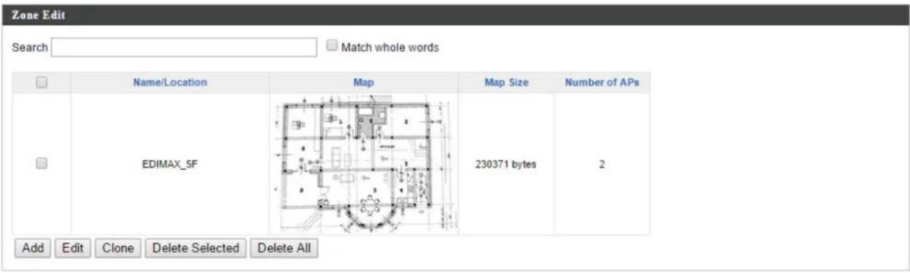
IV-5-6. Zone Edit
Zone Edit displays informaon about zones for use with the Zone Plan feature and allows you to add or edit zones.
The search funcon can be used to nd existing zones. Type in the search box and the list will update:


Make a selecon using the check-boxes and click "Edit" or click "Add" to add a new zone.
Add/Edit Zone
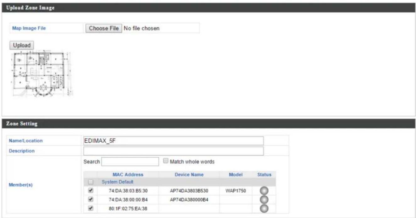
| Upload Zone Image | |
| Choose File | Click to locate an image le to be displayed as a map in the Zone Plan feature. Typically a oor plan image is useful. |
| Zone Seng | |
| Name/Locaoon | Enter a name of the zone/locaon. |
| Descripon | Enter a descripon of the zone/locaon for reference. |
| Members | Assign access points to the specied zone/locaon for use with the Zone Plan feature. |
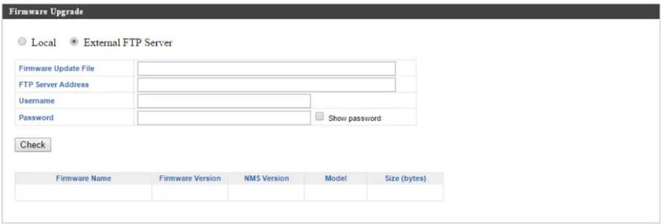
IV-5-7. Firmware Upgrade
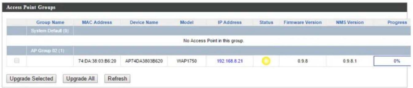
Firmware Upgrade allows you to upgrade rmware to Access Point Groups. First, upload the rmware le from a local disk or external FTP server: locate the le and click "Upload" or "Check". The table below will display the Firmware Name, Firmware Version, NMS Version, Model and Size.
Then click “Upgrade All” to upgrade all access points in the Array or select Access Point groups from the list using check-boxes and click “Upgrade Selected” to upgrade only selected access points.
IV-5-8. Advanced
IV-5-8-1. System Security
Congure the NMS system login name and password.

IV-5-8-2. Date & Time
Congure the date & me sengs of the AP Array. The date and me of the access points can be congured manually or can be synchronized with a me server.



| Date and Time Sengs | |
| Local Time | Set the access point’s date and me manually using the drop down menus. |
| Acquire Current Time from your PC | Click “Acquire Current Time from Your PC” to enter the required values automacally according to your computer’s current me and date. |
| NTP Time Server | |
| Use NTP | The access point also supports NTP (Network Time Protocol) for automac me and date setup. |
| Server Name | Enter the host name or IP address of the me server if you wish. |
| Update Interval | Specify a frequency (in hours) for the access point to update/synchronize with the NTP server. |
| Time Zone | |
| Time Zone | Select the me zone of your country/ region. If your country/region is not listed, please select another country/region whose me zone is the same as yours. |
IV-6. Local Network
IV-6-1. Network Sengs
IV-6-1-1. LAN-Side IP Address
The “LAN-side IP address” page allows you to congregate your AP Controller on your Local Area Network (LAN). You can enable the access point to dynamically receive an IP address from your router’s DHCP server or you can specify a stac IP address for your access point, as well as congregate DNS servers. You can also set your AP Controller as a DHCP server to assign IP addresses to other devices on your LAN.

The access point's default IP address is 192.168.2.2

Disable other DHCP servers on the LAN if using AP Controllers DHCP Server.
| LAN-side IP Address | |
| IP Address Assignment | Static IP Address ▼ |
| IP Address | 192.168.222.220 |
| Subnet Mask | 255.255.255.0 |
| Default Gateway | 192.168.222.1 |
| Primary DNS Address | 0.0.0.0 |
| Secondary DNS Address | 0.0.0.0 |
| LAN-side IP Address | |
| IP Address Assignment | Select “Stac IP” to manually specify a stac/xed IP address for your access point. Select “DHCP Client” for your access point to be assigned a dynamic IP address from your router’s DHCP server, or select “DHCP Server” for your access point to act as a DHCP server and assign IP addresses on your LAN. |
| Stac IP Address | |
| IP Address | Specify the IP address here. This IP address will be assigned to your access point and willreplace the default IP address. |
| Subnet Mask | Specify a subnet mask. The default value is 255.255.255.0 |
| Default Gateway | For DHCP users, select “From DHCP” to get default gateway from your DHCP server or “User-Dened” to enter a gateway manually. For stac IP users, the default value is blank. |
| Primary DNS Address | For stac IP users, the default value is blank. |
| Secondary DNS Address | For stac IP users, the default value is blank. |
LAN-side IP Address
| IP Address Assignment | DHCP Client | |
| IP Address | 192.168.222.220 | |
| Subnet Mask | 255.255.255.0 | |
| Default Gateway | From DHCP ▼ | 192.168.222.1 |
| Primary DNS Address | From DHCP ▼ | 0.0.0.0 |
| Secondary DNS Address | From DHCP ▼ | 0.0.0.0 |
| DHCP Client | |
| IP Address | When “DHCP Client” is selected this value cannot be modied. |
| Subnet Mask | When “DHCP Client” is selected this value cannot be modied. |
| Default Gateway | Select “From DHCP” or select “User-Dened” and enter a default gateway. |
| Primary DNS Address | Select “From DHCP” or select “User-Dened” and enter a primary DNS address. |
| Secondary DNS Address | Select “From DHCP” or select “User-Dened” and enter a secondary DNS address. |
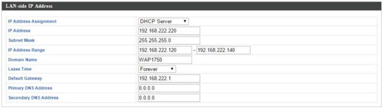


| DHCP Server | |
| IP Address | Specify the IP address here. This IP address will be assigned to your access point and will replace the default IP address. |
| Subnet Mask | Specify a subnet mask. The default value is 255.255.255.0 |
| IP Address Range | Enter the start and end IP address of the IP address range which your access point's DHCP server will assign to devices on the network. |
| Domain Name | Enter a domain name. |
| Lease Time | Select a lease me from the drop down menu. IP addresses will be assigned for this period of me. |
| Default Gateway | Enter a default gateway. |
| Primary DNS Address | Enter a primary DNS address. |
| Secondary DNS Address | Enter a secondary DNS address. |
Your access point's DHCP server can be congured to assign stac (xed) IP addresses to specied network devices, idened by their unique MAC address:
| DHCP Server Stac IP Address | |
| MAC Address | Enter the MAC address of the network deviceto be assigned a stac IP address. |
| IP Address | Specify the IP address to assign the device. |
| Add | Click to assign the IP address to the device. |
IV-6-1-2. LAN Port Sengs
The “LAN Port” page allows you to congregate the sengs for your AP Controllers wired LAN (Ethernet) ports.
| Wired LAN Port Settings | ||||
| Wired LAN Port | Enable | Speed & Duplex | Flow Control | 802.3az |
| Wired Port (#1) | Enabled ▼ | Auto ▼ | Enabled ▼ | Enabled ▼ |
| Wired Port (#2) | Enabled ▼ | Auto ▼ | Enabled ▼ | Enabled ▼ |
| Wired LAN Port | Idenes LAN port 1 or 2. |
| Enable | Enable/disable specied LAN port. |
| Speed & Duplex | Select a speed & duplex type for specied LAN port, or use the “Auto” value. LAN ports can operate up to 1000Mbps and full-duplex enables simultaneous data packets transfer/receive. |
| Flow Control | Enable/disable ow control. Flow control can pause new session request unl current data processing is complete, in order to avoid device overloads under heavy trac. |
| 802.3az | Enable/disable 802.3az. 802.3az is an Energy Ecient Ethernet feature which disables unused interfaces to reduce power usage. |
IV-6-1-3. VLAN
The “VLAN” (Virtual Local Area Network) page enables you to congregate VLAN sengs. A VLAN is a local area network which maps workstaons virtually instead of physically and allows you to group together or isolate users from each other. VLAN IDs 1 – 4094 are supported.

VLAN IDs in the range 1 – 4094 are supported.
![VLAN Interface Wired LAN Port Wired Port (#1) Wired Port (#2) VLAN Mode Untagged Port ▼ Untagged Port ▼ VLAN ID 1 1 Wireless 2.4GHz VLAN Mode VLAN ID SSID [AMPED_DNS_TEST] Untagged Port 1](/content/2026/05/979176/images/4bb07f169871aed16806d4c5c18e3eb053a08a051b17858bc6079b689782805b.jpg)

| VLAN Interface | |
| Wired LAN Port/Wireless | Idenes LAN port 1 or 2 and wireless SSIDs (2.4GHz or 5GHz). |
| VLAN Mode | Select “Tagged Port” or “Untagged Port” for specied LAN interface. |
| VLAN ID | Set a VLAN ID for specied interface, if “Untagged Port” is selected. |
| Management VLAN | |
| VLAN ID | Specify the VLAN ID of the management VLAN. Only the hosts belonging to the same VLAN can manage the device. |
IV-6-2. 2.4GHz 11bgn
The “2.4GHz 11bgn” menu allows you to view and conjure informaon for your access point’s 2.4GHz wireless network across four categories: Basic, Advanced, Security and WDS.
IV-6-2-1. Basic
The “Basic” screen displays basic sengs for your access point’s 2.4GHz Wi-Fi network(s).
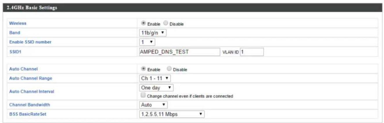


| Wireless | Enable or disable the access point's 2.4GHz wireless radio. When disabled, no 2.4GHz SSIDs will be acve. |
| Band | Select the wireless standard used for the access point. Combinaons of 802.11b, 802.11g & 802.11n can be selected. |
| Enable SSID Number | Select how many SSIDs to enable for the 2.4GHz frequency from the drop down menu. A maximum of 16 can be enabled. |
| SSID# | Enter the SSID name for the specied SSID (upto 16). The SSID can consist of any combinaon of up to 32 alphanumeric characters. |
| VLAN ID | Specify a VLAN ID for each SSID. |
| Auto Channel | Enable/disable auto channel selecon. Auto channel selecon will automacally set the wireless channel for the access point's 2.4GHz frequency based on availability and potenal interference. When disabled, select a channel manually as shown in the next table. |
| Auto Channel Range | Select a range from which the auto channel seng (above) will choose a channel. |
| Auto Channel Interval | Specify a frequency for how oen the auto channel seng will check/reassign the wireless channel. Check/uncheck the “Change channel even if clients are connected” box according to your preference. |
| Channel Bandwidth | Set the channel bandwidth: 20MHz (lower performance but less interference), 40MHz (higher performance but potentially higher interference) or Auto (automacally select based on interference level). |
| BSS BasicRateSet | Set a Basic Service Set (BSS) rate: this is a series of rates to control communicaon frames for wireless clients. |
When auto channel is disabled, select a wireless channel manually:
| Channel | Select a wireless channel from 1 – 11. |
| Channel Bandwidth | Set the channel bandwidth: 20MHz (lower performance but less interference), 40MHz (higher performance but potentially higher interference) or Auto (automacally select based on interference level). |
| BSS BasicRate Set | Set a Basic Service Set (BSS) rate: this is a series of rates to control communicaon frames for wireless clients. |
IV-6-2-2. Advanced
These sengs are for experienced users only. Please do not change any of the values on this page unless you are already familiar with these funcons.

Changing these sengs can adversely act the performance of your access point.
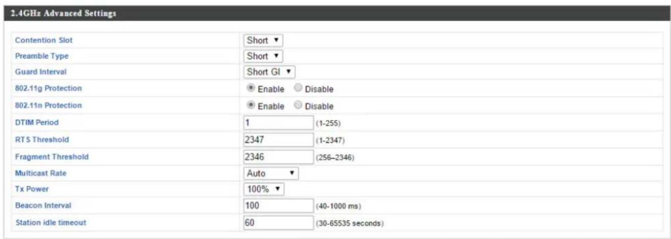
| Contenon Slot | Select “Short” or “Long” – this value is used for contenon windows in WMM (see IV-6-7. WMM). |
| Preamble Type | Set the wireless radio preamble type. The preamble type in 802.11 based wireless communicaon denes the length of the CRC (Cyclic Redundancy Check) block for communicaon between the access point and roaming wireless adapters. The default value is “Short Preamble”. |
| Guard Interval | Set the guard interval. A shorter interval can improve performance. |
| 802.11g Protecon | Enable/disable 802.11g protecon, which increases reliability but reduces bandwidth (clients will send Request to Send (RTS) to access point, and access point will broadcast Clear to Send (CTS), before a packet is sent from client.) |
| 802.11n Protecon | Enable/disable 802.11n protecon, which increases reliability but reduces bandwidth (clients will send Request to Send (RTS) to access point, and access point will broadcast Clear to Send (CTS), before a packet is sent from client.) |
| DTIM Period | Set the DTIM (delivery trac indicaon message) period value of the wireless radio. The default value is 1. |
| RTS Threshold | Set the RTS threshold of the wireless radio. The default value is 2347. |
| Fragment Threshold | Set the fragment threshold of the wireless radio. The default value is 2346. |
| Mulcast Rate | Set the transfer rate for mulcast packets or use the “Auto” seng. |
| Tx Power | Set the power output of the wireless radio. You may not require 100% output power. Seng a lower power output can enhance security since potenally malicious/unknown users in distant areas will not be able to access your signal. |
| Beacon Interval | Set the beacon interval of the wireless radio. The default value is 100. |
| Staon idle meout | Set the interval for keepalive messages from the access point to a wireless client to verify if the staon is sll alive/acve. |
IV-6-2-3. Security
The access point provides various security opons (wireless data encrypon). When data is encrypted, informaon transmied wirelessly cannot be read by anyone who does not know the correct encrypon key.

It's essenal to congregate wireless security in order to prevent unauthorised access to your network.

Select hard-to-guess passwords which include combinaons of numbers, leers and symbols, and change your password regularly.
2.4GHz Wireless Security Settings
| SSID | AMPED_DNS_TEST |
| Broadcast SSID | Enable |
| Wireless Client Isolation | Disable |
| Load Balancing | 50 /50 |
| Authentication Method | No Authentication |
| Additional Authentication | No additional authentication |
| SSID | Select which SSID to congregate security sengs for. |
| Broadcast SSID | Enable or disable SSID broadcast. When enabled, the SSID will be visible to clients as an available Wi-Fi network. When disabled, the SSID will not be visible as an available Wi-Fi network to clients – clients must manually enter the SSID in order to connect. A hidden (disabled) SSID is typically more secure than a visible (enabled) SSID. |
| Wireless Client Isolaon | Enable or disable wireless client isolaon.Wireless client isolaon prevents clients connected to the access point from communicang with each other and improves security. Typically, this funcon is useful for corporate environments or public hot spots and can prevent brute force aacks on clients' usernames and passwords. |
| Load Balancing | Load balancing limits the number of wireless clients connected to an SSID. Set a load balancing value (maximum 50). |
| Authencaon Method | Select an authencaon method from the drop down menu and refer to the informaon below appropriate for your method. |
| Additional Authencaon | Select an additional authencaon method from the drop down menu and refer to the informaon below (IV-6-2-3-6.) appropriate for your method. |
IV-6-2-3-1. No Authencaon
Authencaon is disabled and no password/key is required to connect to the access point.

Disabling wireless authentication is not recommended. When disabled, anybody within range can connect to your device's SSID.
IV-6-2-3-2. WEP
WEP (Wired Equivalent Privacy) is a basic encrypon type. For a higher level of security consider using WPA encrypon.
| Key Length | Select 64-bit or 128-bit. 128-bit is more secure than 64-bit and is recommended. |
| Key Type | Choose from “ASCII” (any alphanumeric character 0-9, a-z and A-Z) or “Hex” (any characters from 0-9, a-f and A-F). |
| Default Key | Select which encrypon key (1 – 4 below) is the default key. For security purposes, you can set up to four keys (below) and change which is the default key. |
| Encrypon Key 1 – 4 | Enter your encrypon key/password according to the format you selected above. |
IV-6-2-3-3. IEEE802.1x/EAP
| Key Length | Select 64-bit or 128-bit. 128-bit is more secure than 64-bit and is recommended. |
IV-6-2-3-4. WPA-PSK
WPA-PSK is a secure wireless encrypon type with strong data protecon and user authencaon, utilizing 128-bit encrypon keys.
| WPA Type | Select from WPA/WPA2 Mixed Mode-PSK, WPA2 or WPA only. WPA2 is safer than WPA only, but not supported by all wireless clients. Please make sure your wireless client supports your selecon. |
| Encrypon | Select “TKIP/AES Mixed Mode” or “AES” encrypon type. |
| Key Renewal Interval | Specify a frequency for key renewal in minutes. |
| Pre-Shared Key Type | Choose from “Passphrase” (8 – 63 alphanumeric characters) or “Hex” (up to 64 characters from 0-9, a-f and A-F). |
| Pre-Shared Key | Please enter a security key/password according to the format you selected above. |
IV-6-2-3-5. WPA-EAP
| WPA Type | Select from WPA/WPA2 Mixed Mode-EAP, WPA2-EAP or WPA-EAP. |
| Encrypon | Select “TKIP/AES Mixed Mode” or “AES” encrypon type. |
| Key Renewal Interval | Specify a frequency for key renewal in minutes. |

WPA-EAP must be disabled to use MAC-RADIUS authencaon.
IV-6-2-3-6. Additional Authencaon
Additional wireless authencaon methods can also be used:
MAC Address Filter
Restrict wireless clients access based on MAC address specied in the MAC Iter table.

See IV-6-6.MAC Filter to congure MAC Itering.
MAC Filter & MAC-RADIUS Authencaon
Restrict wireless clients access using both of the above MAC Itering & RADIUS authencaon methods.
MAC-RADIUS Authencaon
Restrict wireless clients access based on MAC address via a RADIUS server, or password authencaon via a RADIUS server.

See IV-6-5.RADIUS to congregate RADIUS servers.

WPS must be disabled to use MAC-RADIUS authencaon. See IV-6-4. for WPS sengs.
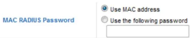
| MAC RADIUSPassword | Select whether to use MAC address or password authencaon via RADIUS server. If you select “Use the following password”, enter the password in the eld below. The password should match the “Shared Secret” used in IV-6-5. RADIUS. |
IV-6-2-4. WDS
Wireless Distribuon System (WDS) can bridge/repeat access points together in an extended network. WDS sengs can be congured as shown below.

When using WDS, conjure the IP address of each access point to be in the same subnet and ensure there is only one acve DHCP server among connected access points, preferably on the WAN side.
WDS must be congured on each access point, using correct MAC addresses. All access points should use the same wireless channel and encrypon method.
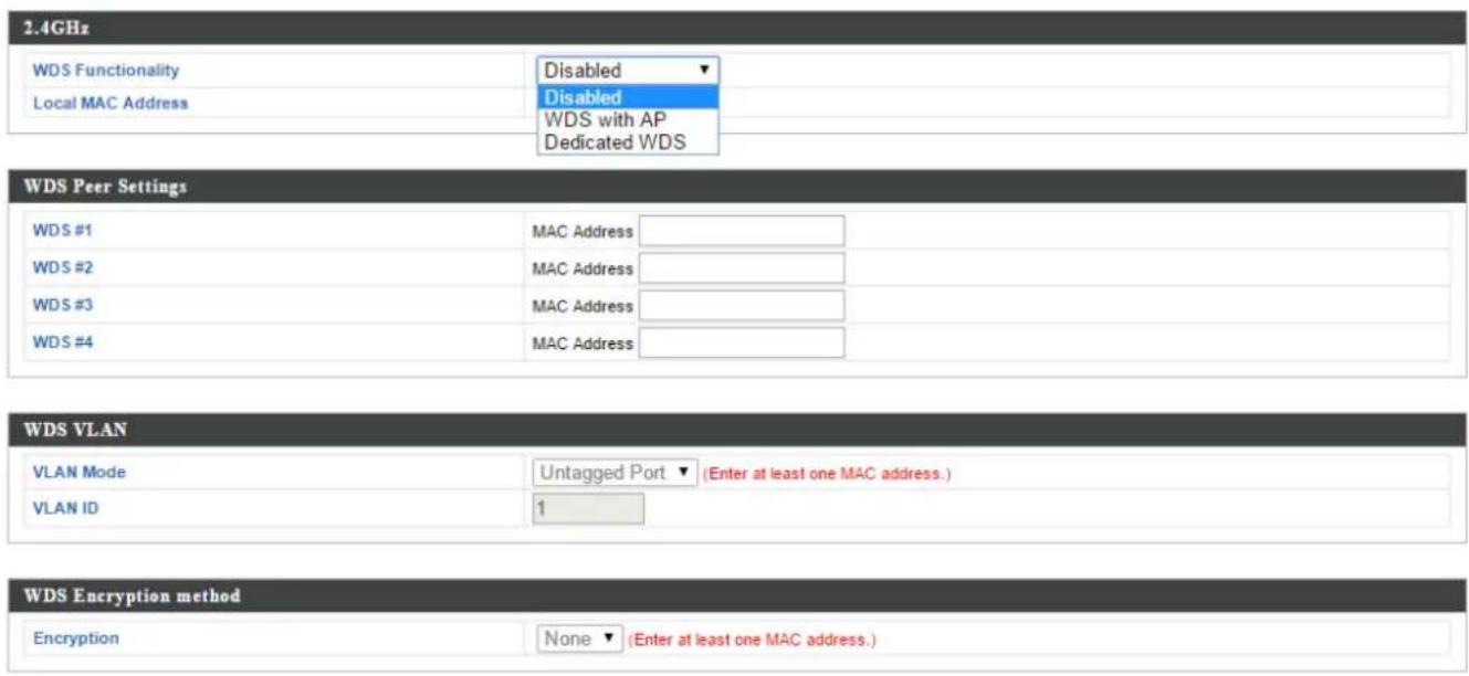
| 2.4GHz | |
| WDS Funconality | Select “WDS with AP” to use WDS with access point or “WDS Dedicated Mode” to use WDS and also block communicaon with regular wireless clients. When WDS is used, each access point should be congured with corresponding MAC addresses, wireless channel and wireless encrypon method. |
| Local MAC Address | Displays the MAC address of your access point. |
| WDS Peer Sengs | |
| WDS # | Enter the MAC address for up to four other WDS devices you wish to connect. |
| WDS VLAN | |
| VLAN Mode | Specify the WDS VLAN mode to “Untagged Port” or “Tagged Port”. |
| VLAN ID | Specify the WDS VLAN ID when “Untagged Port” is selected above. |
| WDS Encrypon method | |
| Encrypon | Select whether to use “None” or “AES” encrypon and enter a pre-shared key for AES consisng of 8-63 alphanumeric characters. |
IV-6-3. 5GHz 11ac 11an
The “5GHz 11ac 11an” menu allows you to view and conjure informaon for your access point’s 5GHz wireless network across four categories: Basic, Advanced, Security and WDS.
IV-6-3-1. Basic
The “Basic” screen displays basic sengs for your access point’s 5GHz Wi-Fi network (s).
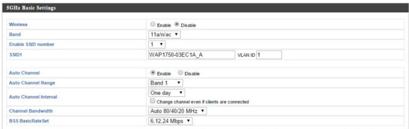


| Wireless | Enable or disable the access point's 5GHz wireless radio. When disabled, no 5GHz SSIDs will be acve. |
| Band | Select the wireless standard used for the access point. Combinaons of 802.11a, 802.11n & 802.11ac can be selected. |
| Enable SSID Number | Select how many SSIDs to enable for the 5GHz frequency from the drop down menu. A maximum of 16 can be enabled. |
| SSID# | Enter the SSID name for the specied SSID (up to 16). The SSID can consist of any combinaon of up to 32 alphanumeric characters. |
| VLAN ID | Specify a VLAN ID for each SSID. |
| Auto Channel | Enable/disable auto channel selecon. Auto channel selecon will automacally set the wireless channel for the access point's 5GHz frequency based on availability and potenal interference. When disabled, select a channel manually as shown in the next table. |
| Auto Channel Range | Select a range from which the auto channel seng (above) will choose a channel. |
| Auto Channel Interval | Specify a frequency for how oen the auto channel seng will check/reassign the wireless channel. Check/uncheck the “Change channel even if clients are connected” box according to your preference. |
| Channel Bandwidth | Set the channel bandwidth: 20MHz (lower performance but less interference), Auto 40/20MHz or Auto 80/40/20MHz (automacally select based on interference level). |
| BSS BasicRate Set | Set a Basic Service Set (BSS) rate: this is a series of rates to control communicaon frames for wireless clients. |
When auto channel is disabled, select a wireless channel manually:
| Channel | Select a wireless channel. |
| Channel Bandwidth | Set the channel bandwidth: 20MHz (lower performance but less interference), Auto 40/20MHz or Auto 80/40/20MHz (automacally select based on interference level). |
| BSS BasicRate Set | Set a Basic Service Set (BSS) rate: this is a series of rates to control communicaon frames for wireless clients. |
IV-6-3-2. Advanced
These sengs are for experienced users only. Please do not change any of the values on this page unless you are already familiar with these funcons.

Changing these sengs can adversely act the performance of your access point.
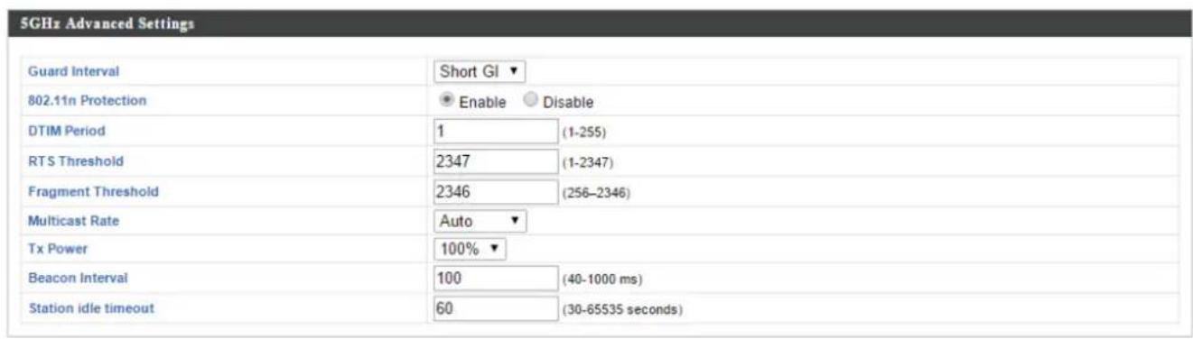
| Guard Interval | Set the guard interval. A shorter interval can improve performance. |
| 802.11n Protecon | Enable/disable 802.11n protecon, which increases reliability but reduces bandwidth (clients will send Request to Send (RTS) to access point, and access point will broadcast Clear to Send (CTS), before a packet is sent from client.) |
| DTIM Period | Set the DTIM (delivery trac indicaon message) period value of the wireless radio. The default value is 1. |
| RTS Threshold | Set the RTS threshold of the wireless radio. The default value is 2347. |
| Fragment Threshold | Set the fragment threshold of the wireless radio. The default value is 2346. |
| Mulcast Rate | Set the transfer rate for mulcast packets or use the “Auto” seng. |
| Tx Power | Set the power output of the wireless radio. You may not require 100% output power. Seng a lower power output can enhance security since potenally malicious/unknown users in distant areas will not be able to access your signal. |
| Beacon Interval | Set the beacon interval of the wireless radio. The default value is 100. |
| Staon idle meout | Set the interval for keepalive messages from the access point to a wireless client to verify if the staon is sll alive/acve. |
IV-6-3-3. Security
The access point provides various security opons (wireless data encrypon). When data is encrypted, informaon transmied wirelessly cannot be read by anyone who does not know the correct encrypon key.

It's essenal to congregate wireless security in order to prevent unauthorised access to your network.

Select hard-to-guess passwords which include combinaons of numbers, leers and symbols, and change your password regularly.
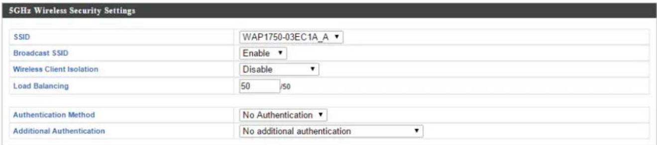
| SSID | Select which SSID to congregate security sengs for. |
| Broadcast SSID | Enable or disable SSID broadcast. When enabled, the SSID will be visible to clients as an available Wi-Fi network. When disabled, the SSID will not be visible as an available Wi-Fi network to clients – clients must manually enter the SSID in order to connect. A hidden (disabled) SSID is typically more secure than a visible (enabled) SSID. |
| Wireless Client Isolaon | Enable or disable wireless client isolaon.Wireless client isolaon prevents clients connected to the access point from communicang with each other and improves security. Typically, this funcon is useful for corporate environments or public hot spots and can prevent brute force aacks on clients' usernames and passwords. |
| Load Balancing | Load balancing limits the number of wireless clients connected to an SSID. Set a load balancing value (maximum 50). |
| Authencaon Method | Select an authencaon method from the drop down menu and refer to the informaon below appropriate for your method. |
| Additional Authencaon | Select an additional authencaon method from the drop down menu and refer to the informaon below appropriate for your method. |
Please refer back to IV-6-2-3. Security for more informaon on authencaon and additional authencaon types.
IV-6-3-4. WDS
Wireless Distribuon System (WDS) can bridge/repeat access points together in an extended network. WDS sengs can be congured as shown below.

When using WDS, conjure the IP address of each access point to be in the same subnet and ensure there is only one acve DHCP server among connected access points, preferably on the WAN side.
WDS must be congured on each access point, using correct MAC addresses. All access points should use the same wireless channel and encrypon method.
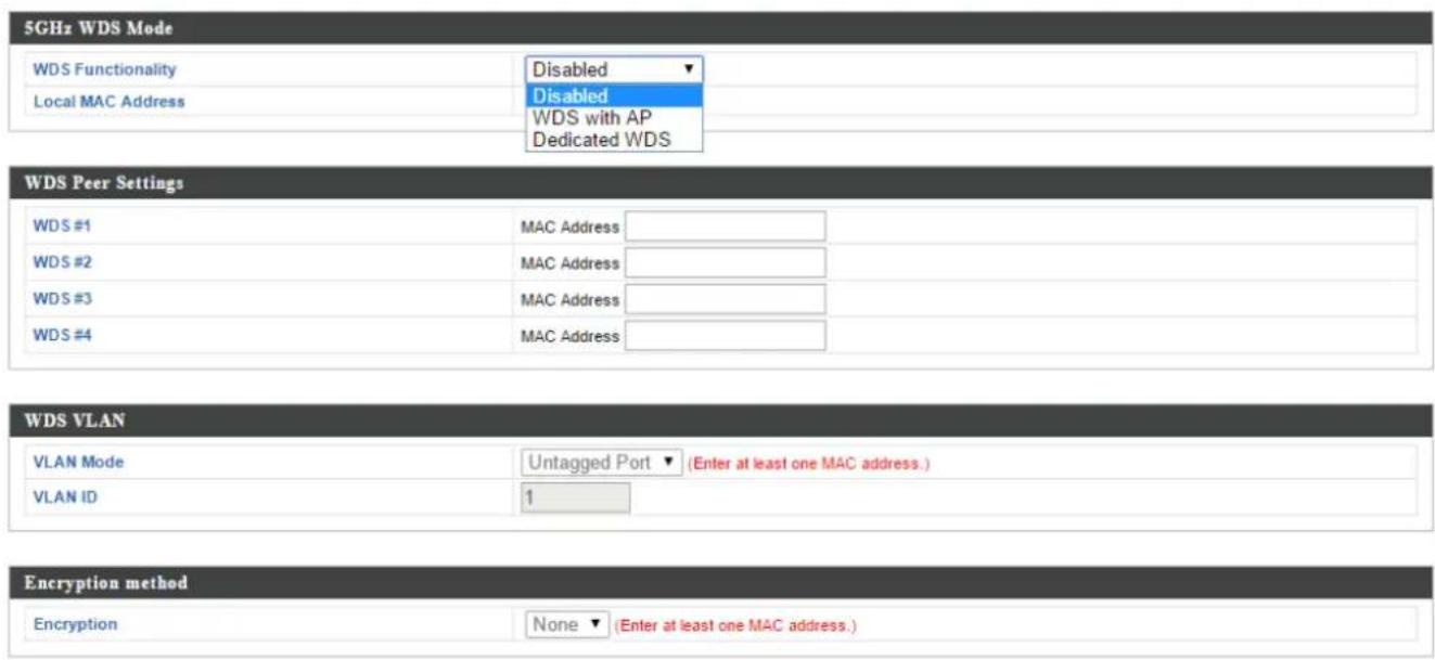
| 5GHz WDS Mode | |
| WDS Funconality | Select “WDS with AP” to use WDS with access point or “WDS Dedicated Mode” to use WDS and also block communicaon with regular wireless clients. When WDS is used, each access point should be congured with corresponding MAC addresses, wireless channel and wireless encrypon method. |
| Local MAC Address | Displays the MAC address of your access point. |
| WDS Peer Sengs | |
| WDS # | Enter the MAC address for up to four other WDA devices you wish to connect. |
| WDS VLAN | |
| VLAN Mode | Specify the WDS VLAN mode to “Untagged Port” or “Tagged Port”. |
| VLAN ID | Specify the WDS VLAN ID when “Untagged Port” is selected above. |
| WDS Encrypon | |
| Encrypon | Select whether to use “None” or “AES” encrypon and enter a pre-shared key for AES with 8-63 alphanumeric characters. |
IV-6-4. WPS
Wi-Fi Protected Setup is a simple way to establish connecons between WPS compatible devices. WPS can be acvated on compatible devices by pushing a WPS buon on the device or from within the device's rmware/conguraon interface (known as PBC or "Push Buon Conguraon"). When WPS is acvated in the correct manner and at the correct me for two compatible devices, they will automacally connect. "PIN code WPS" is a variaon of PBC which includes the additional use of a PIN code between the two devices for vericaon.

Please refer to manufacturer's instrucons for your other WPS device.



| WPS | Check/uncheck this box to enable/disable WPS funconality. WPS must be disabled when using MAC-RADIUS authencaon (see IV-6-2-3-6. & IV-6-5). |
| Product PIN | Displays the WPS PIN code of the device, used for PIN code WPS. You will be required to enter this PIN code into another WPS device for PIN code WPS. Click “Generate PIN” to generate a new WPS PIN code. |
| Push-Buon WPS | Click “Start” to acvate WPS on the access point for approximately 2 minutes. This has the same eect as physically pushing the access point’s WPS buon. |
| WPS by PIN | Enter the PIN code of another WPS device and click “Start” to aempt to establish a WPS conncon for approximately 2 minutes. |
| WPS Status | WPS security status is displayed here. Click “Release” to clear the exisng status. |
IV-6-5. RADIUS
The RADIUS sub menu allows you to congregate the access point's RADIUS server sengs, categorized into three submenus: RADIUS sengs, Internal Server and RADIUS accounts.
A RADIUS server provides user-based authencaon to improve security and offer wireless client control – users can be authenticated before gaining access to a network.
The access point can ulize both a primary and secondary (backup) RADIUS server for each of its wireless frequencies (2.4GHz & 5GHz). External RADIUS servers can be used or the access point's internal RADIUS server can be used.

To use RADIUS servers, go to "Local Network" → "Security" →
"Additional Authencaon" and select "MAC RADIUS
Authencaon" (see IV-6-2-3. & IV-6-3-3).
IV-6-5-1. RADIUS Sengs
Congure the RADIUS server sengs for 2.4GHz & 5GHz. Each frequency can use an internal or external RADIUS server.
RADIUS Server (2.4GHz)
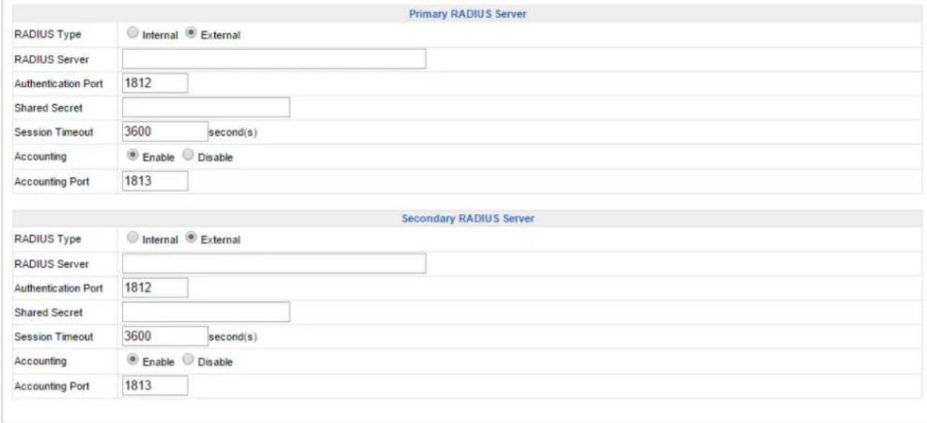
RADIUS Server (5GHz)
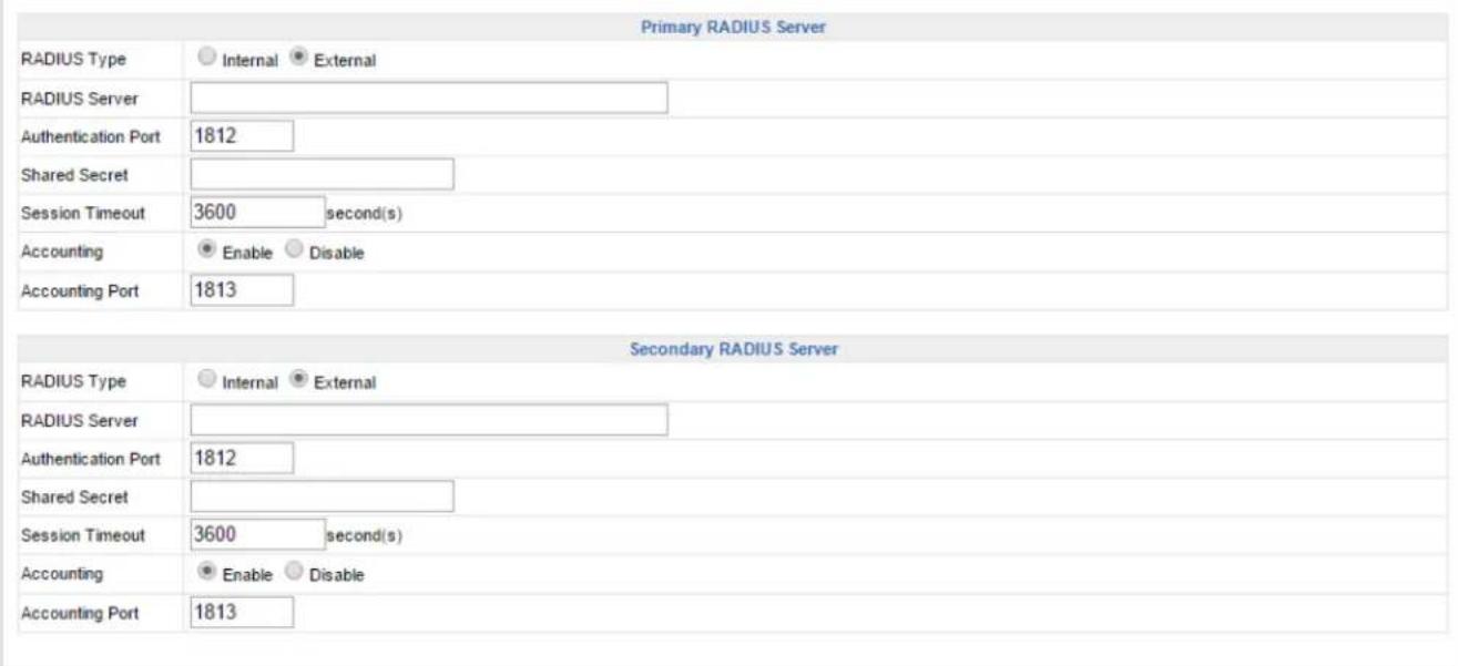
| RADIUS Type | Select “Internal” to use the access point’s built-in RADIUS server or “external” to use an external RADIUS server. |
| RADIUS Server | Enter the RADIUS server host IP address. |
| Authencaon Port | Set the UDP port used in the authencaon protocol of the RADIUS server. Value must be between 1 – 65535. |
| Shared Secret | Enter a shared secret/password between 1 – 99 characters in length. This should match the “MAC-RADIUS” password used in IV-3-1-3-6 or IV-3-2-3. |
| Session Timeout | Set a duraon of session meout in seconds between 0 – 86400. |
| Accounting | Enable or disable RADIUS accoung. |
| Accounting Port | When accoung is enabled (above), set the UDP port used in the accoung protocol of the RADIUS server. Value must be between 1 – 65535. |
IV-6-5-2. Internal Server
The access point features a built-in RADIUS server which can be congured as shown below used when “Internal” is selected for “RADIUS Type” in the “Local Network” → “RADIUS Sengs” menu.

To use RADIUS servers, go to "Wireless Sengs" → "Security"
"Additional Authencaon" and select "MAC RADIUS
Authencaon" (see IV-6-2-3. & IV-6-3-3).
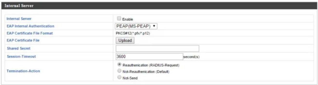
| Internal Server | Check/uncheck to enable/disable the access point's internal RADIUS server. |
| EAP Internal Authencaon | Select EAP internal authencaon type from the drop down menu. |
| EAP Cercate File Format | Displays the EAP cercate le format: PCK#12(*.pfx/*.p12) |
| EAP Cercate File | Click “Upload” to open a new window and select the locaon of an EAP cercate le to use. If no cercate le is uploaded, the internal RADIUS server will use a self-made cercate. |
| Shared Secret | Enter a shared secret/password for use between the internal RADIUS server and RADIUS client. The shared secret should be 1 – 99 characters in length. This should match the “MAC-RADIUS” password used in IV-6-2-3-6 or IV-6-3-3. |
| Session Timeout | Set a duraon of session meout in seconds between 0 – 86400. |
| Terminaon Acon | Select a terminaon-acon aribute: “Reauthencaon” sends a RADIUS request to the access point, “Not-Reathencaon” sends a default terminaon-acon aribute to the access point, “Not-Send” no terminaon-acon aribute is sent to the access point. |
IV-6-5-3. RADIUS Accounts
The internal RADIUS server can authenticate up to 256 user accounts. The "RADIUS Accounts" page allows you to congregate and manage users.
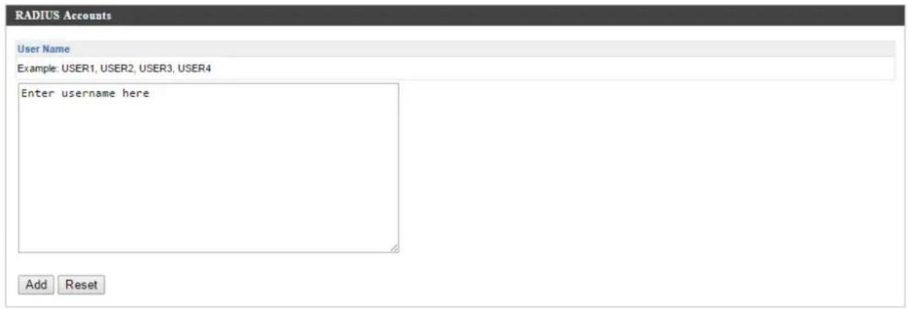
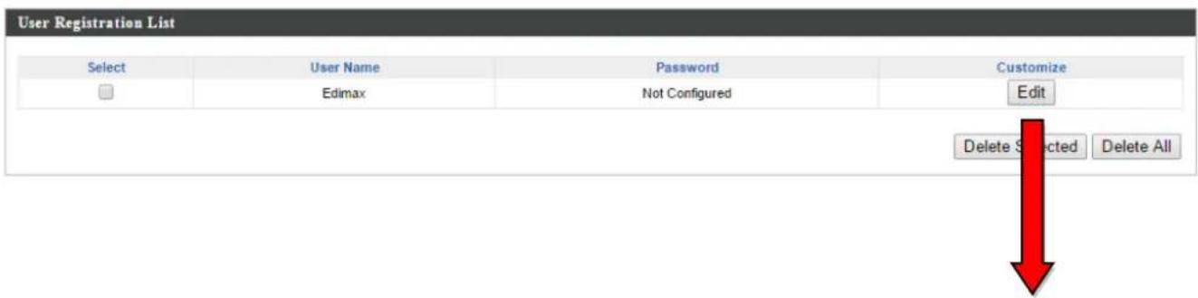

| User Name | Enter the user names here, separated by commas. |
| Add | Click “Add” to add the user to the user registraon list. |
| Reset | Clear text from the user name box. |
| Select | Check the box to select a user. |
| User Name | Displays the user name. |
| Password | Displays if specied user name has a password (congured) or not (not congured). |
| Customize | Click “Edit” to open a new eld to set/edit a password for the specied user name (below). |
| Delete Selected | Delete selected user from the user registraon list. |
| Delete All | Delete all users from the user registraon list. |
Edit User Registraon List
| User Name | Exisng user name is displayed here and can be edited according to your preference. |
| Password | Enter or edit a password for the specied user. |
IV-6-6. MAC Filter
Mac Itering is a security feature that can help to prevent unauthorized users from connecng to your access point.
This funcon allows you to dene a list of network devices permied to connect to the access point. Devices are each idened by their unique MAC address. If a device which is not on the list of permied MAC addresses aempts to connect to the access point, it will be denied.

To enable MAC Itering, go to "Local Sengs" → "Security" →
"Additional Authencaon" and select "MAC Filter" (see IV-6-2-3.
& IV-6-3-3).
The MAC address Itering table is displayed below:
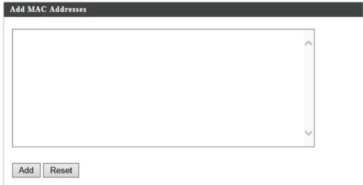
| MAC Address Filtering Table | |
| Select | MAC Address |
| □ | FC:F8:AE:43:43:7E |

| Add MAC Address | Enter a MAC address of computer or network device manually e.g. ‘aa-bb-cc-dd-ee-ff’ or enter mulple MAC addresses separated withcommas, e.g.‘aa-bb-cc-dd-ee-,aa-bb-cc-dd-ee-gg’ |
| Add | Click “Add” to add the MAC address to the MAC address ltering table. |
| Reset | Clear all elds. |
MAC address entries will be listed in the “MAC Address Filtering Table”. Select an entry using the “Select” checkbox.
| Select | Delete selected or all entries from the table. |
| MAC Address | The MAC address is listed here. |
| Delete Selected | Delete the selected MAC address from the list. |
| Delete All | Delete all entries from the MAC addressItering table. |
| Export | Click “Export” to save a copy of the MACItering table. A new window will pop up for you to select a locaon to save the le. |
IV-6-7. WMM
Wi-Fi Mulmedia (WMM) is a Wi-Fi Alliance interoperability cercaon based on the IEEE 802.11e standard, which provides Quality of Service (QoS) features to IEE 802.11 networks. WMM prioritizes trac according to four categories: background, best eort, video and voice.
| WMM Parameters of Access Point | ||||
| CWMin | CWMax | AIFSN | TxOP | |
| Back Ground | 4 | 10 | 7 | 0 |
| Best Effort | 4 | 6 | 3 | 0 |
| Video | 3 | 4 | 1 | 94 |
| Voice | 2 | 3 | 1 | 47 |
| WMM Parameters of Station | ||||
| CWMin | CWMax | AIFSN | TxOP | |
| Back Ground | 4 | 10 | 7 | 0 |
| Best Effort | 4 | 10 | 3 | 0 |
| Video | 3 | 4 | 2 | 94 |
| Voice | 2 | 3 | 2 | 47 |
Conguring WMM consists of adjusng parameters on queues for dierent categories of wireless trac. Trac is sent to the following queues:
| Background | LowPriority | High throughput, non me sensitive bulk data e.g. FTP |
| Best Eort | MediumPriority | Tradional IP data, medium throughput and delay. |
| Video | HighPriority | Time sensitive video data with minimum me delay. |
| Voice | HighPriority | Time sensitive data such as VoIP and streaming media with minimum me delay. |
Queues automacally provide minimum transmission delays for video, voice, mulmedia and crical applicaons. The values can further be adjusted manually:
| CWMin | Minimum Contenon Window (milliseconds):This value is input to the initial randombacko wait me algorithm for retry of a dataframe transmission. The backo wait me willbe generated between 0 and this value. If the frame is not sent, the random backo value is doubled until the value reaches the number dened by CWMax (below). The CWMin value must be lower than the CWMax value. The contenon window scheme helps to avoid frame collisions and determine priority of frame transmission. A shorter window has a higher probability (priority) of transmission. |
| CWMax | Maximum Contenon Window (milliseconds): This value is the upper limit to random backo value doubling (see above). |
| AIFSN | Arbitraon Inter-Frame Space (milliseconds): Species additional me between when a channel goes idle and the AP/client sends data frames. Trac with a lower AIFSN value has a higher priority. |
| TxOP | Transmission Opportunity (milliseconds): The maximum interval of me an AP/client can transmit. This makes channel access more eciently prioritized. A value of 0 means only one frame per transmission. A greater value eects higher priority. |
IV-7. Local Sengs
IV-7-1. Operaon Mode
Set the operaon mode of the access point. AP mode is a standalone access point, AP controller mode acts as the designated master of the AP array, and Managed AP mode acts as a slave AP within the AP array.

IV-7-2. Network Sengs
IV-7-2-1. System Informaon
The "System Informaon" page displays basic system informaon about the access point.
| System | |
| Model | WAP1750 |
| Product Name | AP74DA3803EC1A |
| Uptime | 0 day 20:01:40 |
| Boot from | Internal memory |
| Version | 0.9.12 |
| MAC Address | 74:DA:38:03:EC:1A |
| Management VLAN ID | 1 |
| IP Address | 192.168.222.220 |
| Default Gateway | 192.168.222.1 |
| DNS | ... |
| DHCP Server | ... |
| Wired LAN Port Settings | ||
| Wired LAN Port | Status | VLAN ModeID |
| Wired Port (#1) | Connected (1000 Mbps Full-Duplex) | Untagged Port / 1 |
| Wired Port (#2) | Disconnected (---) | Untagged Port / 1 |
| Wireless 2.4GHz | |
| Status | Enabled |
| MAC Address | 74:DA:38:03:EC:1A |
| Channel | Ch 6 (Auto) |
| Transmit Power | 100% |
| Wireless 2.4GHz /SSID | |||||
| SSID | Authentication Method | Encryption Type | VLAN ID | Additional Authentication | Wireless Client Isolation |
| AMPED_DNS_TEST | WPA/WPA2-PSK | TKIP/AES Mixed Mode | 1 | No additional authentication | Disabled |
| Wireless 2.4GHz /WDS Disabled | ||
| MAC Address | Encryption Type | VLAN Mode/ID |
| No WDS entries. | ||
| System | |
| Model | Displays the model number of the access point. |
| Product Name | Displays the product name for reference, which consists of “AP” plus the MAC address. |
| Upme | Displays the total me since the device was turned on. |
| Boot From | Displays informaon for the booted hardware, booted from either USB or internal memory. |
| Version | Displays the rmware version. |
| MAC Address | Displays the access point’s MAC address. |
| Management VLAN ID | Displays the management VLAN ID. |
| IP Address | Displays the IP address of this device. Click “Refresh” to update this value. |
| Default Gateway | Displays the IP address of the default gateway. |
| DNS | IP address of DNS (Domain Name Server) |
| DHCP Server | IP address of DHCP Server. |
| Wired LAN Port Sengs | |
| Wired LAN Port | Species which LAN port (1 or 2). |
| Status | Displays the status of the specied LAN port(connected or disconnected). |
| VLAN Mode/ID | Displays the VLAN mode (tagged or untagged) and VLAN ID for the specied LAN port. See IV-6-1-3. VLAN |
| Wireless 2.4GHz (5GHz) | |
| Status | Displays the status of the 2.4GHz or 5GHz wireless (enabled or disabled). |
| MAC Address | Displays the access point's MAC address. |
| Channel | Displays the channel number the specied wireless frequency is using for broadcast. |
| Transmit Power | Displays the wireless radio transmit power level as a percentage. |
| Wireless 2.4GHz (5GHz) / SSID | |
| SSID | Displays the SSID name(s) for the specied frequency. |
| Authencaon Method | Displays the authencaon method for the specied SSID. See IV-6. Wireless Sengs |
| Encrypon Type | Displays the encrypon type for the specied SSID. See IV-6. Wireless Sengs |
| VLAN ID | Displays the VLAN ID for the specied SSID. See IV-6-1-3. VLAN |
| Additional Authencaon | Displays the additional authencaon type for the specied SSID. See IV-6. Wireless Sengs |
| Wireless Client Isolaon | Displays whether wireless client isolaon is in use for the specied SSID. See IV-6-1-3. VLAN |
| Wireless 2.4GHz (5GHz) / WDS Status | |
| MAC Address | Displays the peer access point's MAC address. |
| Encrypon Type | Displays the encrypon type for the specied WDS. See IV-6-2-4. WDS |
| VLAN Mode/ID | Displays the VLAN ID for the specied WDS. See IV-6-2-4. WDS |
| Refresh | Click to refresh all informaon. |
IV-7-2-2. Wireless Clients
The “Wireless Clients” page displays informaon about all wireless clients connected to the access point on the 2.4GHz or 5GHz frequency.

| # | SSID | MAC Address | Tx | Rx | Signal (%) | Connected Time | Idle Time | Vendor |
| 1 | AMPED_DNS_TEST | F8:7B:8C:1F:2D:61 | 3.6 KBytes | 7.6 MBytes | 100 | 14 hours 29 min 30 secs | 0 | Amped Wireless |

| Refresh me | |
| Auto Refresh Time | Select a me interval for the client table list to automacally refresh. |
| Manual Refresh | Click refresh to manually refresh the client table. |
| 2.4GHz (5GHz) WLAN Client Table | |
| SSID | Displays the SSID which the client is connected to. |
| MAC Address | Displays the MAC address of the client. |
| Tx | Displays the total data packets transmied by the specied client. |
| Rx | Displays the total data packets received by the specied client. |
| Signal (%) | Displays the wireless signal strength for the specied client. |
| Connected Time | Displays the total me the wireless client has been connected to the access point. |
| Idle Time | Client idle me is the me for which the client has not transmied any data packets i.e. is idle. |
| Vendor | The vendor of the client's wireless adapter is displayed here. |
IV-7-2-3. Wireless Monitor
Wireless Monitor is a tool built into the access point to scan and monitor the surrounding wireless environment. Select a frequency and click “Scan” to display a list of all SSIDs within range along with relevant details for each SSID.

| Ch | SSID | MAC Address | Security | Signal (%) | Type | Vendor |
| 1 | 00:18:0A:D3:4C:F0 | WPA1PSKWPA2PSK /TKIPAES | 84 | b/g/n | Meraki, Inc. | |
| 1 | 11111 | 00:AA:BB:02:01:E0 | NONE | 97 | b/g/n | Unknown |
| 1 | 13213136 | 26:DA:38:00:20:40 | NONE | 98 | b/g/n | Unknown |
| 1 | 22222 | 02:AA:BB:02:01:E0 | NONE | 96 | b/g/n | Unknown |
| 1 | EA3500-2.4G | C8:D7:19:2C:9F:1F | WPA2PSK/AES | 100 | b/g/n | Cisco Consumer Products, LLC |
| Wireless Monitor | |
| Site Survey | Select which frequency (or both) to scan, and click “Scan” to begin. |
| Channel Survey Result | Aer a scan is complete, click “Export” to save the results to local storage. |
| Site Survey Results | |
| Ch | Displays the channel number used by the specied SSID. |
| SSID | Displays the SSID idened by the scan. |
| MAC Address | Displays the MAC address of the wireless router/access point for the specied SSID. |
| Security | Displays the authencaon/encrypon type of the specied SSID. |
| Signal (%) | Displays the current signal strength of the SSID. |
| Type | Displays the 802.11 wireless networking standard(s) of the specied SSID. |
| Vendor | Displays the vendor of the wireless router/access point for the specied SSID. |
IV-7-2-4. Log
The system log displays system operaon informaon such as up me and conncon processes. This informaon is useful for network administrators.

When the log is full, old entries are overwrien.
Jan 1 00:00:51 [SYSTEM]: WLAN[2.4G], Best channel selection start, switch to channel 6
Jan 1 00:00:47 [SYSTEM]: WLAN[2.4G], Best channel selection start, switch to channel 6
Jan 1 00:00:15 [NMS]: start AP Controller successfully
Jan 1 00:00:14 [NMS]: NMS version: 0.9.12.1
Jan 1 00:00:14 [SYSTEM]: Auto Pilot, Stopping
Jan 1 00:00:14 [SYSTEM]: FTP Server, start
Jan 1 00:00:14 [SYSTEM]: TELNETD, start Telnet-cii Server
Jan 1 00:00:14 [SYSTEM]: HTTPS, start
Jan 1 00:00:14 [SYSTEM]: HTTP, start
Jan 1 00:00:13 [SYSTEM]: LAN, Firewall Disabled
Jan 1 00:00:13 [SYSTEM]: LAN, NAT Disabled
Jan 1 00:00:13 [SYSTEM]: NET, Firewall Disabled
Jan 1 00:00:13 [SYSTEM]: NET, NAT Disabled
Jan 1 00:00:13 [SYSTEM]: LEDs, light on specific LEDs
Jan 1 00:00:11 [SYSTEM]: WLAN[5G], Channel = AutoSelect
Jan 1 00:00:11 [SYSTEM]: WLAN[5G], Wireless Mode = 11ACVHT80
Jan 1 00:00:03 [SYSTEM]: WLAN[2.4G], Channel = AutoSelect
Jan 1 00:00:03 [SYSTEM]: WLAN[2.4G], Wireless Mode = 11NGHT40MINUS
Jan 1 00:00:03 [SYSTEM]: LAN, IP address=192.168.222.220
Jan 1 00:00:03 [SYSTEM]: LAN, start
Jan 1 00:00:02 [SYSTEM]: Bridge, start
Jan 1 00:00:02 [SYSTEM]: Bridge, start
Jan 1 00:00:00 [SYSTEM]: SYS, Model Name: Wireless Gigabit Router
Jan 1 00:00:00 [SYSTEM]: SYS, Application Version: 0.9.12
Jan 1 00:00:00 [SYSTEM]: BOOT, WAP1750
Save
Clear
Refresh
| Save | Click to save the log as a le on your local computer. |
| Clear | Clear all log entries. |
| Refresh | Refresh the current log. |
The following informaon/events are recorded by the log:
USB
Mount & unmount
◆ Wireless Client
Connected & disconnected
Key exchange success & fail
◆ Authencaon
Authencaon fail or successful.
Associaon
Success or fail
WPS
M1 - M8 messages
WPS success
◆ Change Sengs
◆ System Boot
Displays current model name
◆ NTP Client
◆ Wired Link
LAN Port link status and speed status
◆ Proxy ARP
Proxy ARP module start & stop
◆ Bridge
Bridge start & stop.
SNMP
SNMP server start & stop.
◆ HTTP
HTTP start & stop.
HTTPS
HTTPS start & stop.
◆ SSH
SSH-client server start & stop.
Telnet
Telnet-client server start or stop.
♦ WLAN (2.4G)
WLAN (2.4G] channel status and country/region status
♦ WLAN (5G)
WLAN (5G) channel status and country/region status
ADT
IV-7-3. Management
IV-7-3-1. Admin
You can change the password used to login to the browser-based conguraon interface here. It is advised to do so for security purposes.

If you change the administrator password, please make a note of the new password. In the event that you forget this password and are unable to login to the browser based conguraon interface, see IV-7-4-4. Factory Default for how to reset the access point.

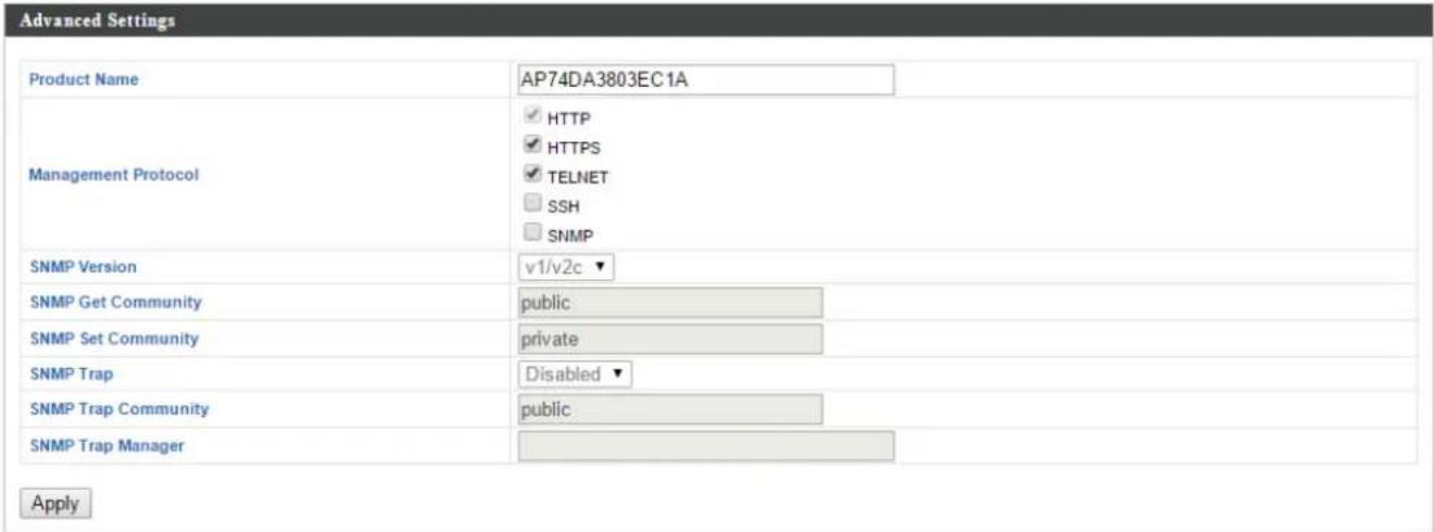
| Account to Manage This Device | |
| Administrator Name | Set the access point's administrator name. This is used to log in to the browser based conguraon interface and must be between 4-16 alphanumeric characters (case sensitive). |
| Administrator Password | Set the access point's administrator password. This is used to log in to the browser based conguraon interface and must be between4-32 alphanumeric characters (case sensitive). |
| Advanced Sengs | |
| Product Name | Edit the product name according to your preference consisng of 1-32 alphanumeric characters. This name is used for reference purposes. |
| Management Protocol | Check/uncheck the boxes to enable/disable specied management interfaces (see below). When SNMP is enabled, complete the SNMP elds below. |
| SNMP Version | Select SNMP version appropriate for your SNMP manager. |
| SNMP Get Community | Enter an SNMP Get Community name for vericaon with the SNMP manager for SNMP-GET requests. |
| SNMP Set Community | Enter an SNMP Set Community name for vericaon with the SNMP manager for SNMP-SET requests. |
| SNMP Trap | Enable or disable SNMP Trap to nofy SNMP manager of network errors. |
| SNMP Trap Community | Enter an SNMP Trap Community name for vericaon with the SNMP manager for SNMP-TRAP requests. |
| SNMP Trap Manager | Specify the IP address or sever name (2-128 alphanumeric characters) of the SNMP manager. |
HTTP
Internet browser HTTP protocol management interface
HTTPS
Internet browser HTTPS protocol management interface
TELNET
Client terminal with telnet protocol management interface
SSH
Client terminal with SSH protocol version 1 or 2 management interface
SNMP
Simple Network Management Protocol. SNMPv1, v2 & v3 protocol supported.
SNMPv2 can be used with community based authencaon. SNMPv3 uses user-based security model (USM) architecture.
IV-7-3-2. Date and Time
You can congregate the me zone sengs of your access point here. The date and me of the device can be congregate manually or can be synchronized with a me server.



| Date and Time Sengs | |
| Local Time | Set the access point’s date and me manually using the drop down menus. |
| Acquire Current Time from your PC | Click “Acquire Current Time from Your PC” to enter the required values automacally according to your computer’s current me and date. |
| NTP Time Server | |
| Use NTP | The access point also supports NTP (Network Time Protocol) for automac me and date setup. |
| Server Name | Enter the host name or IP address of the me server if you wish. |
| Update Interval | Specify a frequency (in hours) for the access point to update/synchronize with the NTP server. |
| Time Zone | |
| Time Zone | Select the me zone of your country/ region. Ifyour country/region is not listed, please select another country/region whose me zone is the same as yours. |
IV-7-3-3. Syslog Server
The system log can be sent to a server, aached to USB storage or sent via email.
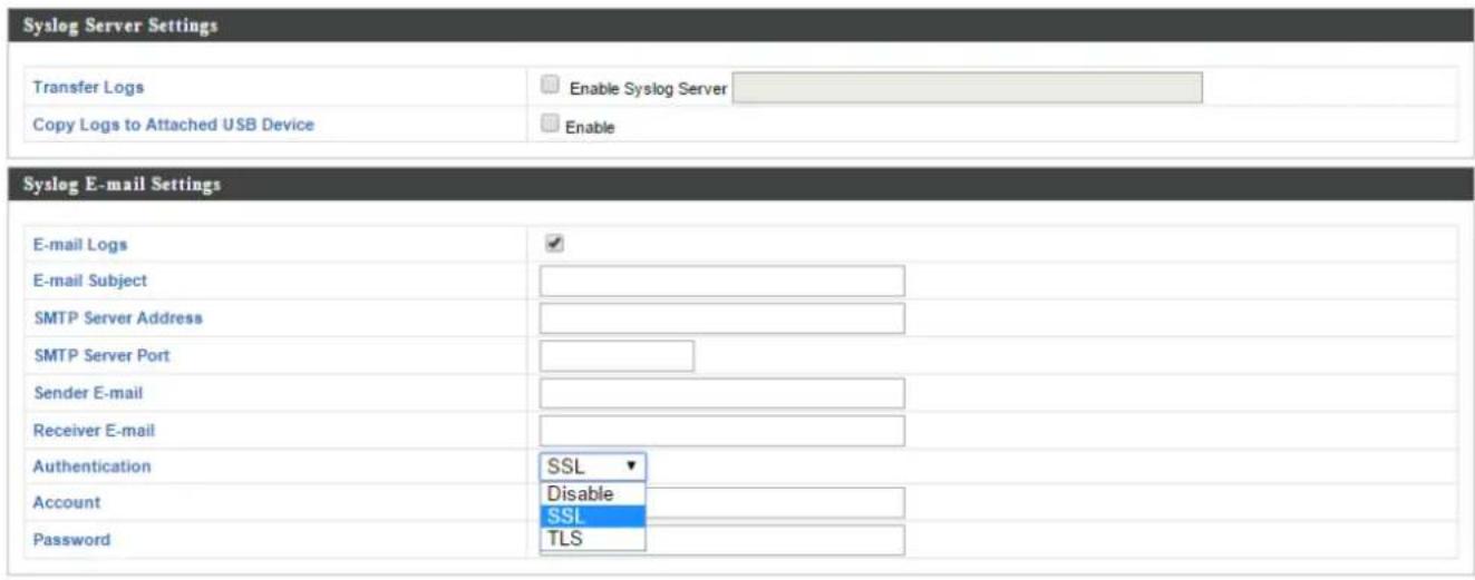
| Syslog Server Sengs | |
| Transfer Logs | Check/uncheck the box to enable/disable the use of a syslog server, and enter a host name, domain or IP address for the server, consisng of up to 128 alphanumeric characters. |
| Copy Logs to Aached USB Device | Check/uncheck the box to enable/disable copying logs to aached USB storage. |
| Syslog Email Sengs | |
| Email Logs | Check/uncheck the box to enable/disable email logs. When enabled, the log will be emailed according to the sengs below. |
| Email Subject | Enter the subject line of the email which will be sent containing the log. |
| SMTP Server Address | Specify the SMTP server address for the sender email account. |
| SMTP Server Port | Specify the SMTP server port for the sender email account. |
| Sender Email | Enter the sender's email address. |
| Receiver Email | Specify the email recipient of the log. |
| Authencaon | Select “Disable”, “SSL” or “TLS” according toyour email authencaon. |
| Account | When authencaon is used above, enter the account name. |
| Password | When authencaon is used above, enter the password. |
IV-7-3-4. I'm Here
The access point features a built-in buzzer which can sound on command using the “I’m Here” page. This is useful for network administrators and engineers working in complex network environments to locate the access point.


The buzzer is loud!
| Duraon of Sound | Set the duraon for which the buzzer will sound when the “Sound Buzzer” buon is clicked. |
| Sound Buzzer | Acvate the buzzer sound for the above specied duraon of me. |
IV-7-4. Advanced
Wi-Fi Mulmedia (WMM) is a Wi-Fi Alliance interoperability cercaon based on the IEEE 802.11e standard, which provides Quality of Service (QoS) features to IEE 802.11 networks. WMM prioritizes trac according to four categories: background, best eort, video and voice.
IV-7-4-1. LED Sengs
The access point's LEDs can be manually enabled or disabled according to your preference.

| Power LED | Select on or o. |
| Diag LED | Select on or o. |
IV-7-4-2. Update Firmware
The “Firmware” page allows you to update the system rmware to a more recent version. Updated rmware versions oen oer increased performance and security, as well as bug xes. You can download the latest rmware from the Edimax website.

This rmware update is for an individual access point. To update rmware for mulple access points in the AP array, go to NMS Sengs → Firmware Upgrade.



Do not switch o or disconnect the access point during a rmware upgrade, as this could damage the device.
| Update Firmware From | Select “a le on your PC” to upload rmware from your local computer or from an aached USB device. |
| Firmware Update File | Click “Browse” to open a new window to locate and select the rmware le in your computer. |
| Update | Click “Update” to upload the specied rmware le to your access point. |
IV-7-4-3. Save/Restore Sengs
The access point's "Save/Restore Setngs" page enables you to save/backup the access point's current sengs as a le to your local computer or a USB device aached to the access point, and restore the access point to previously saved sengs.
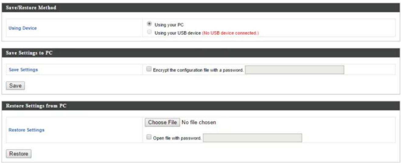
| Save / Restore Sengs | |
| Using Device | Select “Using your PC” to save the access point’s sengs to your local computer or to an aached USB device. |
| Save Sengs to PC | |
| Save Sengs | Click “Save” to save sengs and a new window will open to specify a locaon to save the sengs le. You can also check the “Encrypt the conguraon le with a password” box and enter a password to protect the le in the eld underneath, if you wish. |
| Restore Sengs from PC | |
| Restore Sengs | Click the browse buon to nd a previously saved sengs le on your computer, then click “Restore” to replace your current sengs. If your sengs le is encrypted with a password, check the “Open le withpassword” box and enter the password in the eld underneath. |
IV-7-4-4. Factory Default
If the access point malfuncons or is not responding, then it is recommended that you reboot the device (see IV-7-4-5.) or reset the device back to its factory default sengs. You can reset the access point back to its default sengs using this feature if the locaon of the access point is not convenient to access the reset buon.
This will restore all settings to factory defaults.
Factory Default
| Factory Default | Click “Factory Default” to restore sengs to the factory default. A pop-up window will appear and ask you to conrm. |

Aer reseng to factory defaults, please wait for the access point to reset and restart.
IV-7-4-5. Reboot
If the access point malfuncons or is not responding, then it is recommended that you reboot the device or reset the access point back to its factory default sengs (see IV-7-4-4). You can reboot the access point remotely using this feature.
This will reboot the product. Your settings will not be changed. Click "Reboot" to reboot the product now.
Reboot
| Reboot | Click “Reboot” to reboot the device. A countdown will indicate the progress of the reboot. |
IV-8. Toolbox
IV-8-1. Network Connecvity
IV-8-1-1. Ping
Ping is a computer network administraon ulity used to test whether a parcular host is reachable across an IP network and to measure the round-trip me for sent messages.

| Desnaon Address | Enter the address of the host. |
| Execute | Click execute to ping the host. |
Traceroute is a diagnosc tool for displaying the route (path) and measuring transit delays of packets across an IP network.
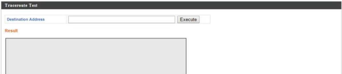
| Desnaon Address | Enter the address of the host. |
| Execute | Click execute to execute the traceroute command. |
V-1. Conguring your IP address
The access point uses the default IP address 192.168.2.2. In order to access the browser based conguraon interface, you need to modify the IP address of your computer to be in the same IP address subnet e.g. 192.168.2.x (x = 3 - 254).
The procedure for modifying your IP address varies across dierent operang systems; please follow the guide appropriate for your operang system.
In the following examples we use the IP address 192.168.2.10 though you can use any IP address in the range 192.168.2.x (x = 3 - 254).
If you changed the AP Controller's IP address, or if your gateway/router uses a DHCP server, ensure you enter the correct IP address. Refer to your gateway/router's sengs. Your computer's IP address must be in the same subnet as the AP Controller.
If using a DHCP server on the network, it is advised to use your DHCP server's sengs to assign the AP Controller a stac IP address.
V-1-1. Windows XP
- Click the “Start” buon (it should be located in the lower-le corner of your computer), then click “Control Panel”. Double-click the “Network and Internet Connecons” icon, click “Network Connecons”, and then double-click “Local Area Connecon”. The “Local Area Connecon Status” window will then appear, click “Properes”.
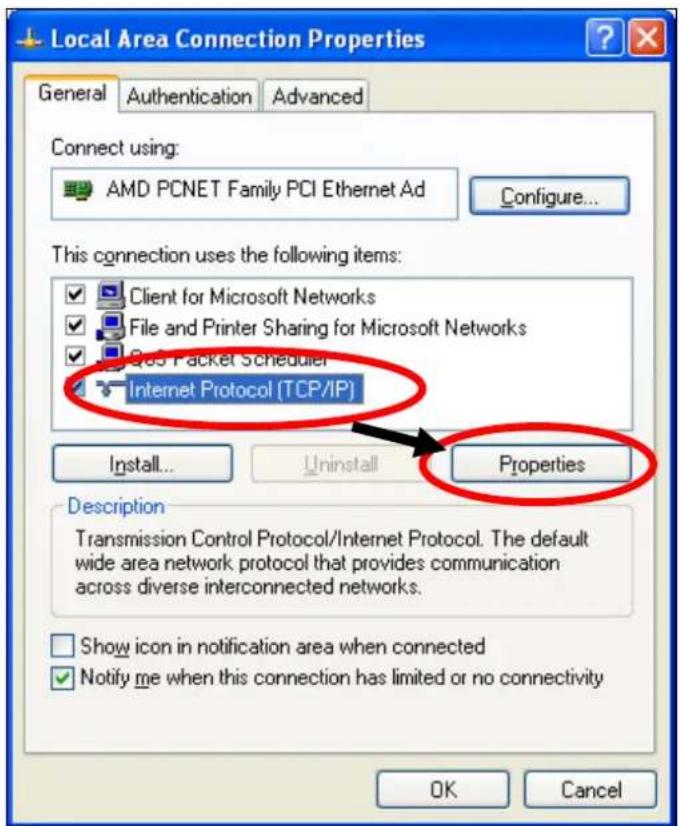
- Select "Use the following IP address", then input the following values:
IP address: 192.168.2.10
Subnet Mask: 255.255.255.0
Click 'OK' when nished.
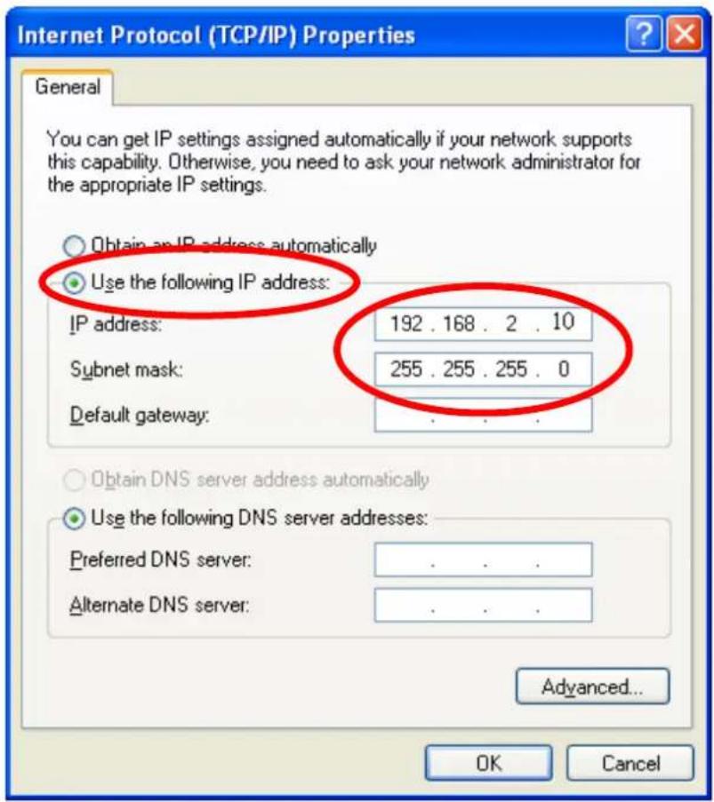
V-1-2. Windows Vista
- Click the “Start” buon (it should be located in the lower-le corner of your computer), then click “Control Panel”. Click “View Network Status and Tasks”, then click “Manage Network Connecons”. Right-click “Local Area Network”, then select “Properes”. The “Local Area Connecon Properes” window will then appear, select “Internet Protocol Version 4 (TCP / IPv4)”, and then click “Properes”.
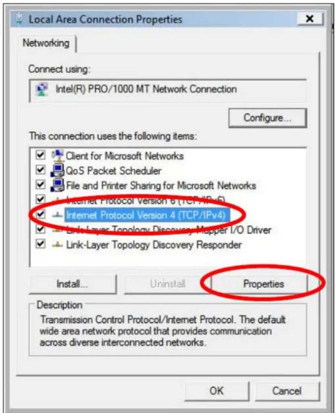
- Select "Use the following IP address", then input the following values:
IP address: 192.168.2.10
Subnet Mask: 255.255.255.0
Click 'OK' when nished.
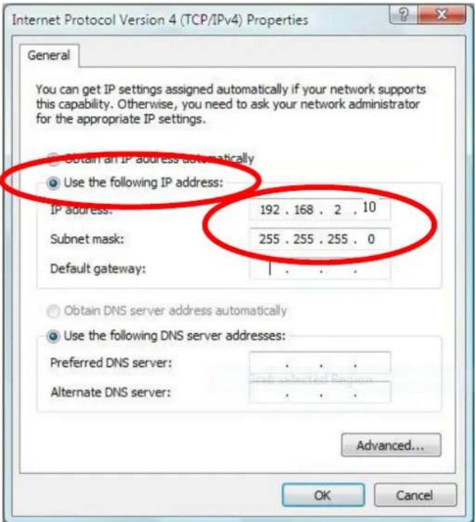
V-1-3. Windows 7
- Click the "Start" buon (it should be located in the lower-le corner of your computer), then click "Control Panel".
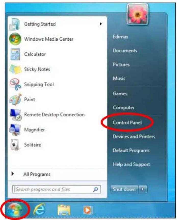
- Under "Network and Internet" click "View network status and tasks".
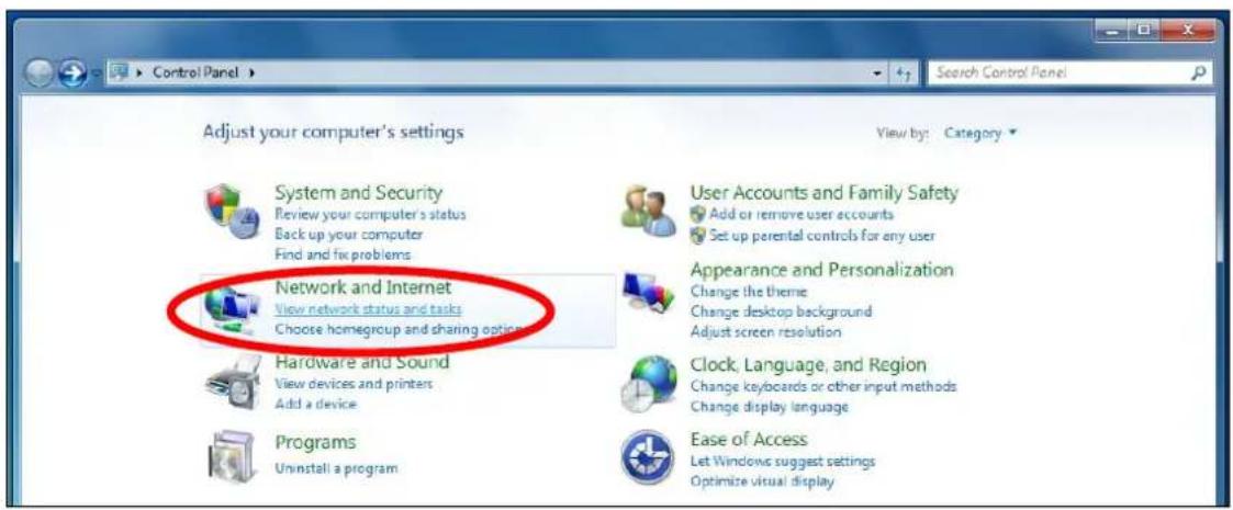
- Click "Local Area Connecon".
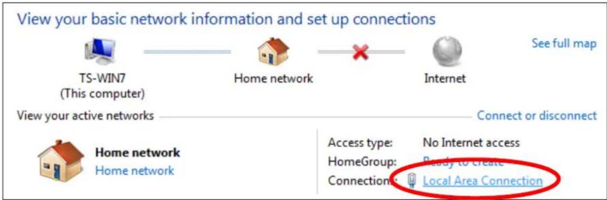
4. Click "Properes".
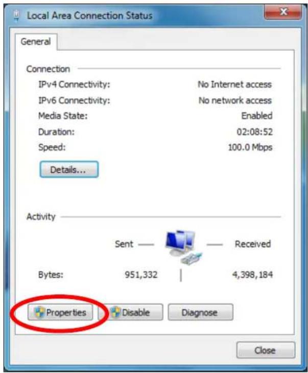
- Select "Internet Protocol Version 4 (TCP/IPv4) and then click "Properes".
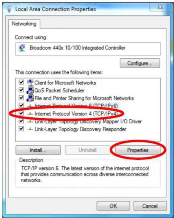
- Select "Use the following IP address", then input the following values:
IP address: 192.168.2.10
Subnet Mask: 255.255.255.0
Click 'OK' when nished.
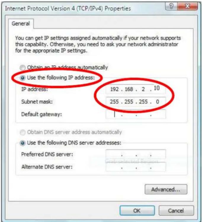
V-1-4. Windows 8
- From the Windows 8 Start screen, you need to switch to desktop mode. Move your cursor to the boom le of the screen and click.
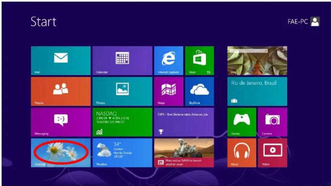
- In desktop mode, click the File Explorer icon in the boom le of the screen, as shown below.

natural_image
Close-up of white daisies against a blue sky, with no visible text or symbols on the daisies or background.3. Right click "Network" and then select "Properes".
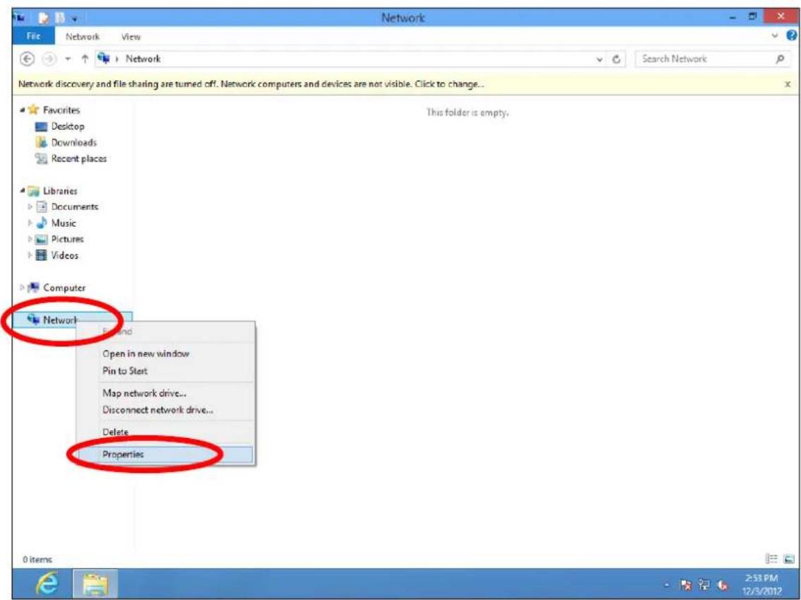
4. In the window that opens, select "Change adapter sengs" from the le
side.
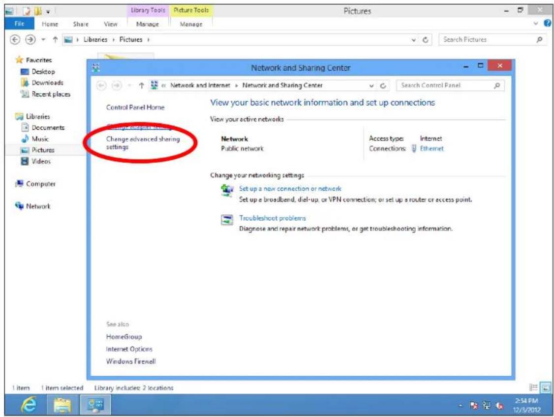
5. Choose your conncon and right click, then select "Properes".
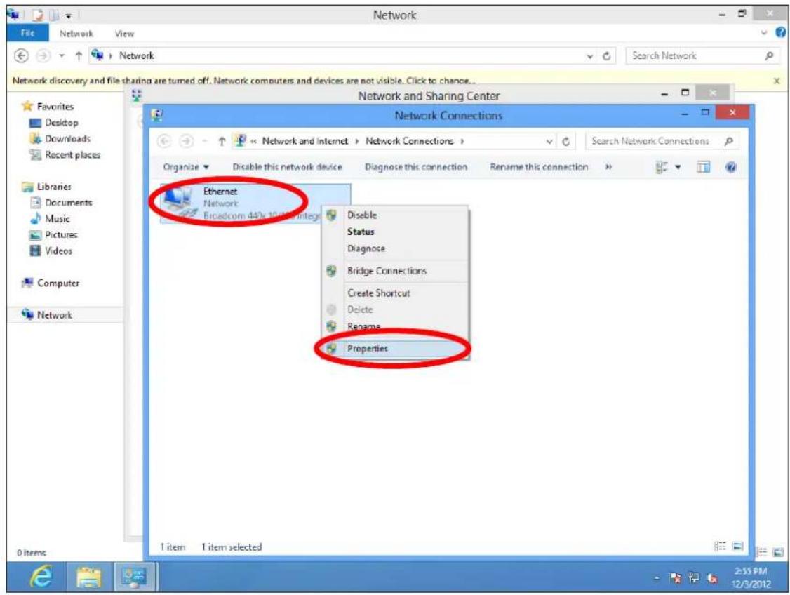
6. Select "Internet Protocol Version 4 (TCP/IPv4) and then click "Properes".
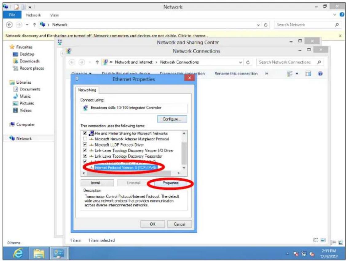
7. Select "Use the following IP address", then input the following values:
IP address: 192.168.2.10
Subnet Mask: 255.255.255.0
Click 'OK' when nished.
V-1-5. Mac
- Have your Macintosh computer operate as usual, and click on "System Preferences"

- In System Preferences, click on "Network".
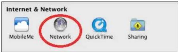
- Click on "Ethernet" in the le panel.
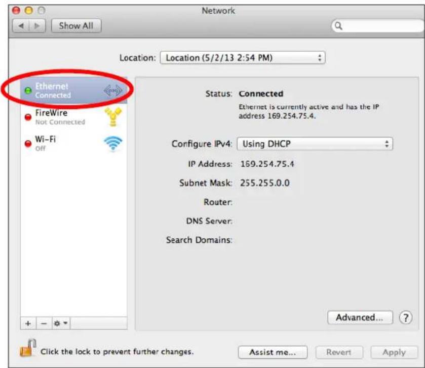
- Open the drop-down menu labeled "Congure IPv4" and select "Manually".
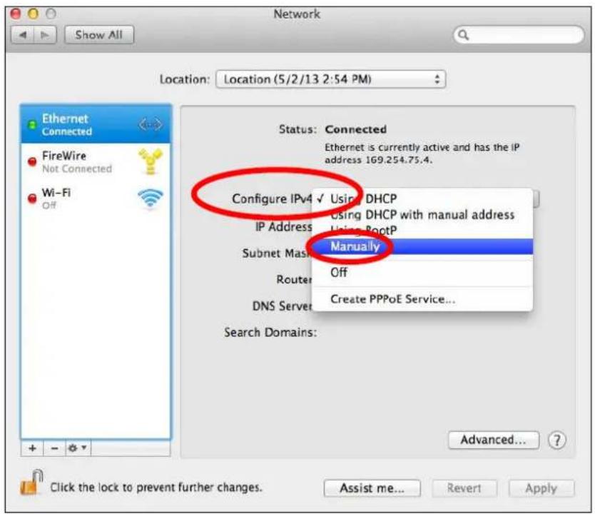
- Enter the IP address 192.168.2.10 and subnet mask 255.255.255.0. Click on “Apply” to save the changes.
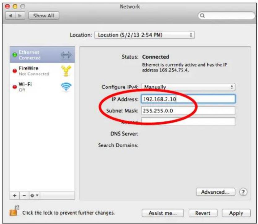
VI-1. How to Create and Link WLAN & Access Point Groups
You can use NMS to create individual SSIDs and group mulple SSIDs together into WLAN groups. You can then assign individual access points to use those WLAN group sengs and/or group mulple access points together into access point groups, which you can also assign to use WLAN group sengs.
Follow the example below to:
A. Create a WLAN group.
B. Create an access point group.
C. Assign the access point group to use the SSID group sengs.
A.
- Go to NMS Sengs → WLAN and click "Add" in the WLAN panel:
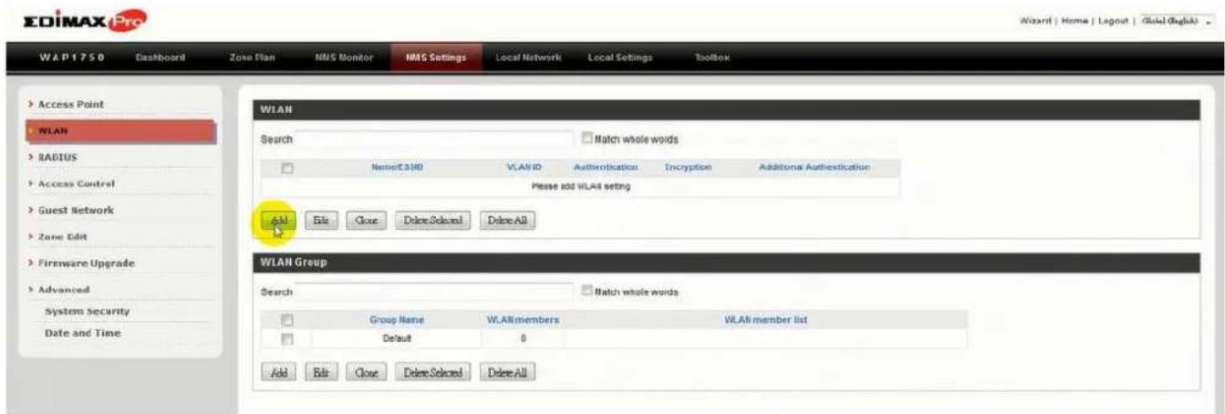
- Enter an SSID name and set authencaon/encrypon and click "Apply":
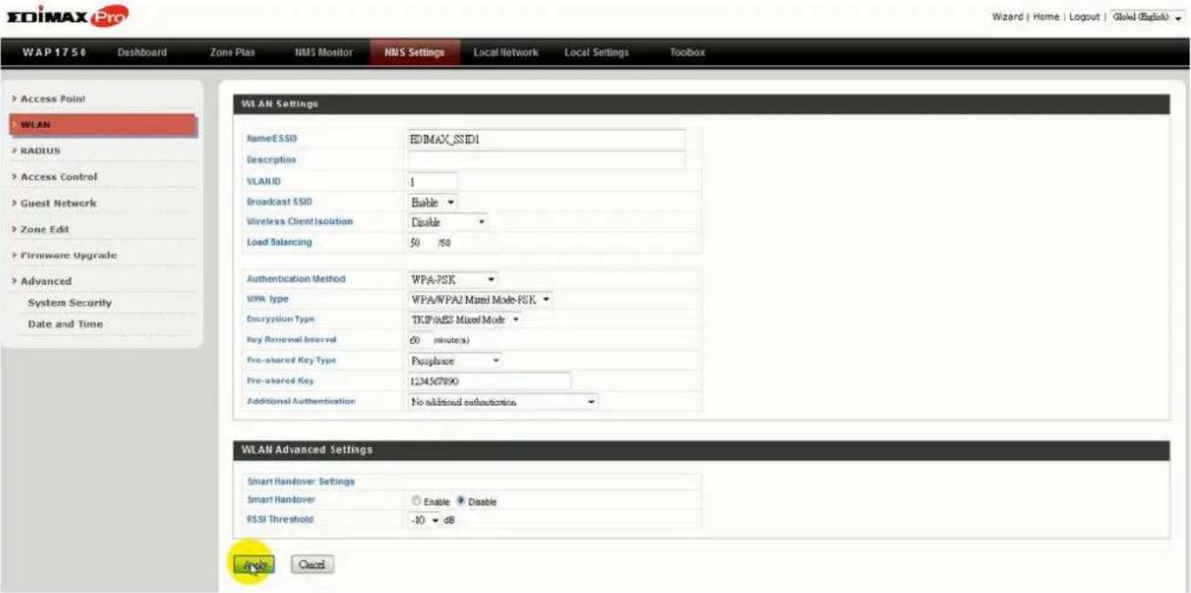
- The new SSID will be displayed in the WLAN panel. Repeat to add additional SSIDs according to your preference, and then click "Add" in the WLAN Group panel:
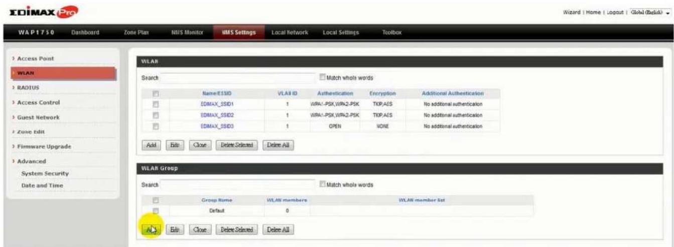
- Enter a name for the SSID group and check the boxes to select which SSIDs to include within the group. Click "Apply" when done.
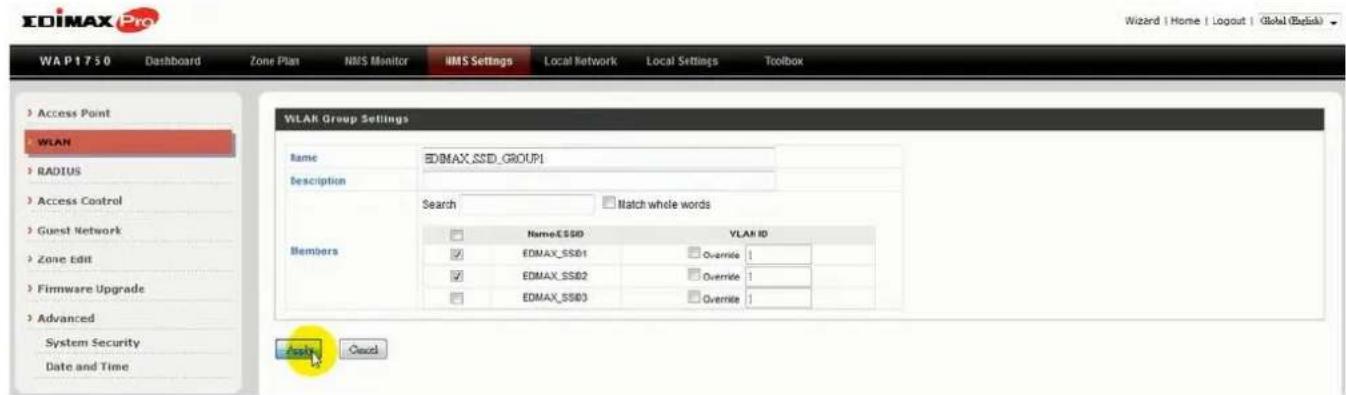
- The new WLAN group will be displayed in the WLAN Group panel. Repeat to add additional WLAN groups according to your preference:
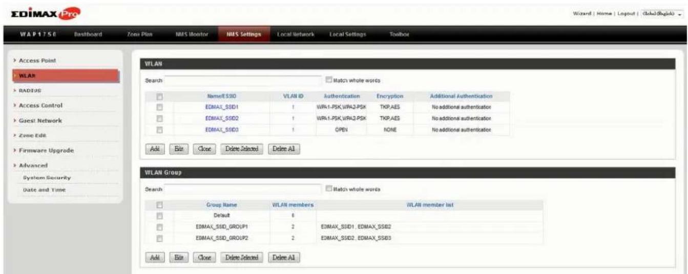
B.
- Go to NMS Sengs → Access Point and click "Add" in the Access Point Group Panel:
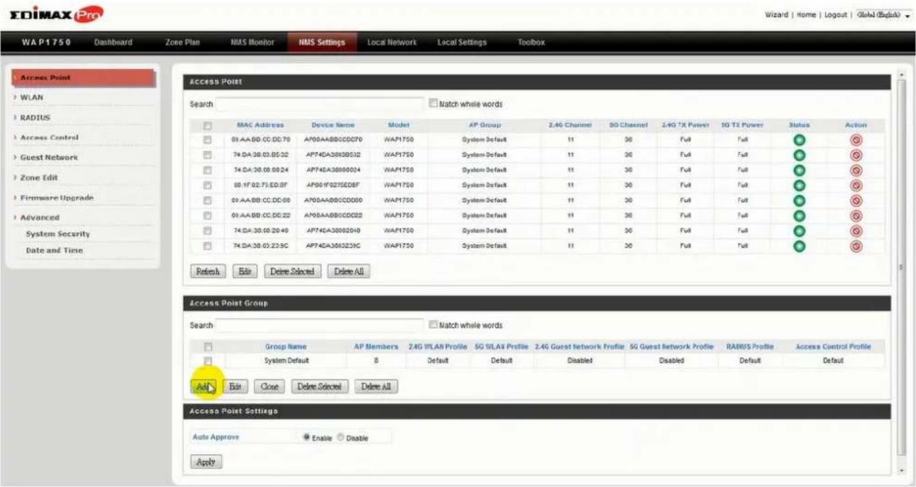
- Enter a Name and then scroll down to the Group Sengs panel and use the << buon to add selected access points into your group from the box on the right side. Click "Apply" when done.
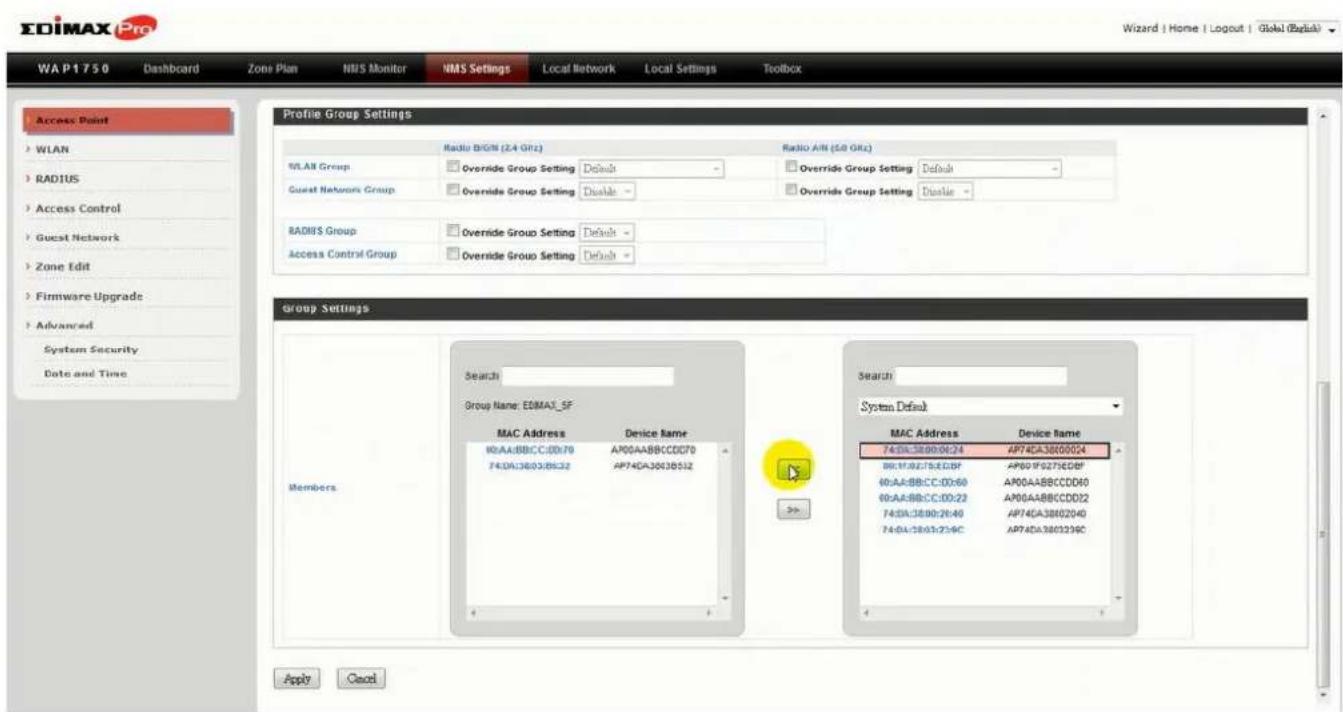
- The new access point group will be displayed in the Access Point Group panel. Repeat to add additional access point groups according to your preference:
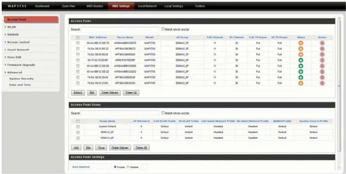
C.
- Go to NMS Sengs → Access Point and select an access point group using the checkboxes in the Access Point Group panel. Click "Edit":
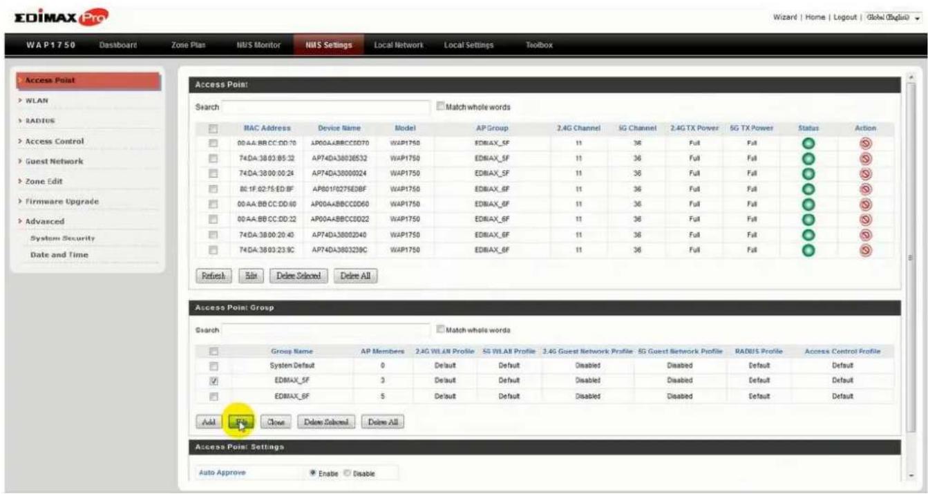
- Scroll down to the Prole Group Sengs panel and check the “Override Group Sengs” box for WLAN Group (2.4GHz and/or 5GHz). Select your WLAN group from the drop-down menu and click “Apply”:
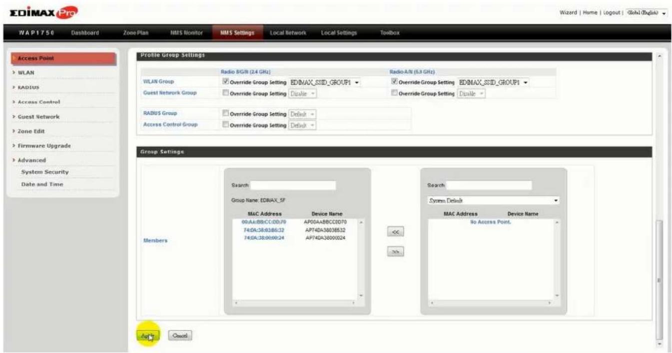
- Repeat for other access point groups according to your preference.
COPYRIGHT
Copyright © Edimax Technology Co., Ltd. all rights reserved. No part of this publicaon may be reproduced, transmied, transcribed, stored in a retrieval system, or translated into any language or computer language, in any form or by any means, electronic, mechanical, magnec, opcal, chemical, manual or otherwise, without the prior written permission from Edimax Technology Co., Ltd.
Edimax Technology Co., Ltd. makes no representaons or warranes, either expressed or implied, with respect to the contents hereof and specifically disclaims any warranes, merchantability, or tness for any parcular purpose. Any soware described in this manual is sold or licensed as is. Should the programs prove defecve following their purchase, the buyer (and not this company, its distributor, or its dealer) assumes the enre cost of all necessary servicing, repair, and any incidental or consequential damages resulting from any defect in the soware. Edimax Technology Co., Ltd. reserves the right to revise this publicaon and to make changes from me to me in the contents hereof without the obligaon to nofy any person of such revision or changes.
The product you have purchased and the setup screen may appear slightly dierent from those shown in this QIG. The soware and specicaons are subject to change without noce. Please visit our website www.edimax.com for updates. All brand and product names menoned in this manual are trademarks and/or registered trademarks of their respective holders.
ΣDIMAX
NETWORKING PEOPLE TOGETHER
- Edimax Technology Europe B.V.
- Edimax Computer Company
- Contents
- IV-6. Local Network 71
- IV-7. Local Sengs 105
- Appendix ......124
- Best Pracce ....139
- Product Informaon
- Dashboard
- Zone Plan
- NMS Monitor
- NMS Sengs
- Local Network
- Local Sengs
- EDIMAX Pro
- Toolbox
- IV-1. LOGIN, LOGOUT & RESTART
- LOGIN
- LOGOUT
- RESTART
- IV-2. DASHBOARD
- IV-2-1. System Informaon
- IV-2-2. Devices Informaon
- IV-2-3. Managed AP
- Disallow
- Edit
- Blink LED
- Buzzer
- Network Connecvity
- Restart
- IV-2-4. Managed AP Group
- IV-2-5. Acve Clients
- IV-3. ZONE PLAN
- IV-4. NMS MONITOR
- IV-4-1. Access Point
- IV-4-1-1. Managed AP
- Edit
- Blink LED
- Buzzer
- Network Connecvity
- Restart
- IV-4-1-2. Managed AP Group
- Disallow
- Edit
- Blink LED
- Buzzer
- Network Connecvity
- Restart
- IV-4-2. WLAN
- IV-4-2-1. Acve WLAN
- IV-4-2-2. Acve WLAN Group
- IV-4-3. Clients
- IV-4-3-1. Acve Clients
- IV-4-4. Rogue Devices
- IV-4-5. Informaon
- IV-4-5-1. All Events/Acvies
- IV-4-5-2. Monitoring
- IV-5. NMS Sengs
- IV-5-1. Access Point
- Edit Access Point
- Add/Edit Access Point Group
- IV-5-2. WLAN
- Add/Edit WLAN Group
- IV-5-3. RADIUS
- Add/Edit External RADIUS Server
- Add/Edit Internal RADIUS Server
- Add/Edit RADIUS Accounts
- Add/Edit RADIUS Group
- IV-5-4. Access Control
- Add/Edit MAC Access Control
- Add/Edit MAC Access Control Group
- IV-5-5. Guest Network
- Add/Edit Guest Network Group
- IV-5-6. Zone Edit
- Add/Edit Zone
- IV-5-7. Firmware Upgrade
- IV-5-8. Advanced
- IV-5-8-1. System Security
- IV-5-8-2. Date & Time
- IV-6. Local Network
- IV-6-1. Network Sengs
- IV-6-1-1. LAN-Side IP Address
- IV-6-1-2. LAN Port Sengs
- IV-6-1-3. VLAN
- VLAN IDs in the range 1 – 4094 are supported.
- IV-6-2. 2.4GHz 11bgn
- IV-6-2-1. Basic
- IV-6-2-2. Advanced
- IV-6-2-3. Security
- IV-6-2-3-1. No Authencaon
- IV-6-2-3-2. WEP
- IV-6-2-3-3. IEEE802.1x/EAP
- IV-6-2-3-4. WPA-PSK
- IV-6-2-3-5. WPA-EAP
- IV-6-2-3-6. Additional Authencaon
- MAC Address Filter
- MAC Filter & MAC-RADIUS Authencaon
- MAC-RADIUS Authencaon
- IV-6-2-4. WDS
- IV-6-3. 5GHz 11ac 11an
- IV-6-3-1. Basic
- IV-6-3-2. Advanced
- IV-6-3-3. Security
- IV-6-3-4. WDS
- IV-6-4. WPS
- IV-6-5. RADIUS
- IV-6-5-1. RADIUS Sengs
- IV-6-5-2. Internal Server
- IV-6-5-3. RADIUS Accounts
- IV-6-6. MAC Filter
- IV-6-7. WMM
- IV-7. Local Sengs
- IV-7-1. Operaon Mode
- IV-7-2. Network Sengs
- IV-7-2-1. System Informaon
- IV-7-2-2. Wireless Clients
- SSID MAC Address Tx Rx Signal (%) Connected Time Idle Time Vendor
- IV-7-2-3. Wireless Monitor
- IV-7-2-4. Log
- When the log is full, old entries are overwrien.
- IV-7-3. Management
- IV-7-3-1. Admin
- HTTP
- HTTPS
- TELNET
- SSH
- SNMP
- IV-7-3-2. Date and Time
- IV-7-3-3. Syslog Server
- IV-7-3-4. I'm Here
- The buzzer is loud!
- IV-7-4. Advanced
- IV-7-4-1. LED Sengs
- IV-7-4-2. Update Firmware
- IV-7-4-3. Save/Restore Sengs
- IV-7-4-4. Factory Default
- IV-7-4-5. Reboot
- IV-8. Toolbox
- IV-8-1. Network Connecvity
- IV-8-1-1. Ping
- V-1. Conguring your IP address
- V-1-1. Windows XP
- V-1-2. Windows Vista
- V-1-3. Windows 7
- Click "Properes".
- V-1-4. Windows 8
- Right click "Network" and then select "Properes".
- In the window that opens, select "Change adapter sengs" from the le
- Choose your conncon and right click, then select "Properes".
- Select "Internet Protocol Version 4 (TCP/IPv4) and then click "Properes".
- Select "Use the following IP address", then input the following values:
- V-1-5. Mac
- VI-1. How to Create and Link WLAN & Access Point Groups
- A.
- B.
- C.
- COPYRIGHT
- ΣDIMAX
- NETWORKING PEOPLE TOGETHER
Brand : Edimax
Model : Pro NMS
Category : NAS