MMPP4301-PKG - Uncategorized Micro Matic - Free user manual and instructions
Find the device manual for free MMPP4301-PKG Micro Matic in PDF.


| Product Type | Glycol Power Pack |
| Model | MMPP4301-PKG |
| Dimensions (H x W x D) | 30" x 18" x 26" |
| Weight | 130 lbs |
| Voltage | 115 V |
| Running Amps | 17.5 A |
| Plug Type | L5-30P |
| Cooling Distance | 125 ft |
| Number of Glycol Pumps | 2 |
| Pump Type | Procon (Vane) |
| Pump Flow Rate | 80 GPH each |
| Motor Horsepower | 1/3 HP |
| Refrigerant | R134a |
| Refrigerant Charge | 12 oz |
| BTUs per Hour | 2,600 |
| Bath Capacity | 11.5 gal |
| Bath Insulation Thickness | 1.5" |
| Approval | ETL Listed |
| Ambient Operating Temperature | 50 °F - 90 °F (air cooled) |
| Minimum Clearance (above/in front) | 18 inches |
| Glycol Solution Mixture (standard) | 2.5 parts water to 1 part Micro Matic Polar Flo glycol |
| Glycol Change Interval | Every 18 months |
| Condenser Cleaning Interval | Every 60 days |
| Warranty (power pack) | 18 months |
| Warranty (compressor) | 5 years |
Frequently Asked Questions - MMPP4301-PKG Micro Matic
User questions about MMPP4301-PKG Micro Matic
0 question about this device. Answer the ones you know or ask your own.
Ask a new question about this device
Download the instructions for your Uncategorized in PDF format for free! Find your manual MMPP4301-PKG - Micro Matic and take your electronic device back in hand. On this page are published all the documents necessary for the use of your device. MMPP4301-PKG by Micro Matic.
USER MANUAL MMPP4301-PKG Micro Matic
Power Pack Service Manual
MMPP4301-EP
MMPP4301
MMPP4301-WC
MMPP4301-PKG
MMPP4301-PKG-WC
MMPP4302
MMPP4302-WC
MMPP4302-PKG
MMPP4302-PKG-WC
MMPP4303-PKG
MMPP4303-PKG-WC
MMPP4303-PKG-3
MMPP4305-PKG
MMPP4305-PKG-WC
MMPP4305-PKG-3
TABLE OF CONTENTS
Equipment Specifications 2
Installation and Operation .... 3
75' Unit 3
125', 250', 350' and 500' Units ....4
Maintenance 4
Electronic Temperature Control with Display 5
Changing a Glycol Pump....6
Replacing Motor 7
Replacing Thermostat 7
Troubleshooting 8
Typical Spare Parts 9
Wiring Diagrams....10
Warranty 15
EQUIPMENT SPECIFICATIONS
| Air Cooled | MMPP4301-EP | MMPP4301 | MMPP4301-PKG | MMPP4302 | MMPP4302-PKG | MMPP4303-PKG | MMPP4303-PKG-3 | MMPP4305-PKG | MMPP4305-PKG-3 |
| Water Cooled | MMPP4301-WC | MMPP4301-PKG-WC M | MMPP4302-WC M | MMPP4302-PKG-WC MM | MMPP4303-PKG-WC MM | MMPP4305-PKG-WC | |||
| Cooling Distance | 75' | 125' | 125' | 250' | 250' | 350' | 350' | 500' | 500' |
| Glycol Pumps | 1 | 1 | 2 | 1 | 2 | 2 | 3 | 2 | 3 |
| Pump Type | Vertical | Procon (Vane) | Procon (Vane) | Procon (Vane) | Procon (Vane) | Procon (Vane) | Procon (Vane) | Procon (Vane) | Procon (Vane) |
| Pump GPH | 240 | 80 | 80 | 80 | 80 | 80 | 80 | 80 | 80 |
| Motor HP | 1/3 | 1/3 | 1/3 | 1/2 | 1/2 | 3/4 | 3/4 | 1 | 1 |
| Voltage | 115 | 115 | 115 | 115 | 115 | 220 | 220 | 220 | 220 |
| Plug Type | 5-15P | 5-15P | L5-30P | 5-20P | L5-30P | 6-15P | 6-20P | 6-15P | 6-20P |
| Amps (Running) 7.0 | 11.5 | 17.5 | 15.3 | 21.1 | 10.6 | 10.6 | 11.0 | 14 | |
| 11.5 | 15.5 | ||||||||
| Refrigerant | R134a | R134a | R134a | R134a | R134a | R134a | R134a | R134a | R134a |
| Charge (oz.) | 10 | 12 | 12 | 16 | 16 | 16 | 16 | 48 | 48 |
| Refrigeration Pressure | 185 (low)235 (high) | 185 (low)235 (high) | 185 (low)235 (high) | 185 (low)235 (high) | 185 (low)235 (high) | 185 (low)235 (high) | 185 (low)235 (high) | 185 (low)235 (high) | 185 (low)2 35 (high) |
| BTUs/H | 2,300 | 2,600 | 2,600 | 3,400 | 3,400 | 5,000 | 5,000 | 7,000 | 7,000 |
| Dimensions H x W x D Including pump(s) and motor(s) | 19" x 17" x 26" | 30" x 18" x 26" | 30" x 18" x 26" | 30" x 18" x 26" | 30" x 18" x 26" | 30" x 18" x 26" | 30" x 25" x 26" | 30" x 18" x 26" | 30" x 25" x 26" |
| Weight (lbs) | 90 | 110 | 130 | 130 | 170 | 170 | 170 | 190 | 205 |
| Bath Capacity (gal) | 5 | 11.5 | 11.5 | 11.5 | 11.5 | 11.5 | 11.5 | 11.5 | 11.5 |
| Bath Insulation Thickness | 1.5" | 1.5" | 1.5" | 1.5" | 1.5" | 1.5" | 1.5" | 1.5" | 1.5" |
| Approval | ETL Listed | ETL Listed | ETL Listed | ETL Listed | ETL Listed | ETL Listed | ETL Listed | ETL Listed | ETL Listed |
Micro Matic reserves the right to change specifications without notice.
INSTALLATION AND OPERATION
- Remove packaging from the unit in the vicinity of the area where it will be installed.
- Carefully lift the unit into the desired position.
NOTE: DO NOT PUSH OR SLIDE UNIT – Damage will be caused to the legs if the unit is pushed into position.
PLACEMENT
- It is not recommended to install a power pack on top of a walk in cooler.
- It is not recommended to install a power pack outside.
• Always ensure a minimum clearance of 18 inches above and in front of a power pack.
This allows for proper air flow around unit.
- Ambient operating temperature range is 50 - 90^ for all air cooled models.
- Power pack must be wired to a ground fault circuit interrupter per UL guidelines.
75' UNIT INSTALLATION STEPS
(Assure tower connections are complete.)
- Connect one of the glycol tubes to the pump inlet. Insulate any exposed tubing.
- Connect the second glycol line to the pump outlet. Insulate any exposed tubing.
- Carefully push the glycol bath lid to one side, allowing sufficient space to fill the bath with liquid.
- Inspect the bath for debris.
- Fill the glycol bath with Micro Matic Polar Flo glycol solution (mixed 2 12 parts water to 1 part glycol) Fill the bath to the full level on the glycol level indicator.
- Connect unit to the electrical outlets capable of handling the required voltage loads. This should be carried out by suitably trained personnel and comply with all state and national electrical codes.
- Glycol level will fall as glycol is pumped through the glycol lines. Continue to fill the bath to the fill level on the glycol level indicator.
- Replace top cover.
- Inspect for any leaks.
- Glycol temperature will fall slowly to 29^ F.
NOTE: To adjust the glycol temperature, please see Adjusting Electronic Thermostat.
125', 250', 350' AND 500' UNITS INSTALLATION STEPS
(Assure tower connections are complete.)
- Remove the refrigeration deck from the unit.
- Inspect the glycol tank for any debris.
-
Connect one of the glycol lines from the trunk line to the pump outlet. Insulate any exposed tubing.
NOTE: In units with more than one pump, connect a glycol line to each pump outlet. -
Connect the second glycol line from each circuit to the glycol bath inlet.
-
Fill the glycol bath with Micro Matic Polar Flo glycol solution:
- 125', 250' and 350' units: 2 12 parts water to 1 part glycol.
- 500' unit: 1 part distilled water to 1 part glycol.
Fill bath to the level of the fill line on the glycol level indicator.
-
Replace the refrigeration deck.
-
Remove electrical outlets capable of handling the required voltage loads. This should be carried out by suitably trained personnel and must comply with all state and national codes.
-
Glycol level will fall as glycol is pumped through the glycol lines. Continue to fill the bath to the full level on the glycol level indicator.
-
Inspect for any leaks.
-
Temperature of the glycol will fall slowly to 29^ F.
NOTE: To adjust the glycol temperature, please see Adjusting Electronic Thermostat.
MAINTENANCE
- Inspect the unit monthly to ensure that the glycol level is maintained to the full level.
- If the level is low replace with a Micro Matic Polar Flo glycol solution:
- 75', 125', 250' and 350' units: mixed 2 12 parts water to 1 part glycol.
- 500' units: 1 part distilled water to 1 part glycol.
- If there is evidence of ice build up in the unit, allow the ice to melt and replace all the water/glycol solution with a fresh solution mixed per above instructions.
- The glycol/water solution should be changed approximately every 18 months. In regions of high humidity considerations should be given to replacing the solution on an annual basis.
- Check and clean the condenser fins every sixty (60) days.
- Check that there is adequate air flow through the unit ensuring enough space all around and that there are no obstructions in front of the air flow vents.
- Check the condition and effectiveness of the trunk line insulation.
- At regular intervals, to be determined by the owner, the unit should be checked for electrical safety.
ELECTRONIC TEMPERATURE CONTROL WITH DISPLAY
NOTE: When the unit leaves the factory the electronic thermostat is pre-set to the following parameters:
| Temperature Scale: F (Fahrenheit) | ||
| Setpoint: | 29° | F |
| Differential: | 3° | F |
NOTE: To ensure the correct operation of your unit these parameters must be adhered to.
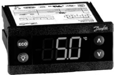
User/customer can change the temperature by pressing the up and down arrows.
CHANGING A GLYCOL PUMP 75' UNIT
- Unplug unit from receptacle.
- Remove four (4) screws holding pump to bath lid.
- Cut tubing slightly above outlet fitting on pump.
- Remove pump through hole in top of bath lid.
- Insert new pump through opening in lid.
- Attach pump outlet hose and clamp with stainless steel clamp.
- Replace mounting screws and plug unit into receptacle.
125', 250', 350' AND 500' UNITS
Note: A pinch off tool is required to complete this repair
- Unplug unit from receptacle.
- Pinch off glycol supply line to bottom of pump allowing enough room to remove clamp safely.
- Hold pump firmly and loosen clamp between pump and motor.
- With clamp loose remove pump and drive key.
- Install new key and pump by reattaching clamp making sure alignment of key is correct between pump and motor.
- Reattach glycol supply hose and install clamp.
- Remove pinch off tool and plug unit into receptacle.
REPLACING MOTOR 125', 250', 350' AND 500' UNITS
Note: Replacement motor is not supplied with electrical cord. Remove and reuse cord from defective motor.
- Unplug unit from receptacle.
- Support pump and loosen clamp holding pump to motor. As clamp is loosed pump will eventually disconnect from motor. Make sure pump does not damage glycol supply line as it becomes free from motor.
- With pump free from motor remove drive key and replace.
- While supporting motor remove four (4) nuts and hardware from mounting studs.
- Mount new motor by aligning mounting bracket with mounting studs and reattaching mounting nuts and hardware. Note: new motor is supplied with mounting bracket.
- Reattach pump to motor with clamp making sure new drive key aligns with motor shaft.
- Locate defective motor and remove electrical connection cover plate (follow cord to where it enters back of motor) exposing cord connections. Remove ground connection by unscrewing green screw and removing ground wire. Unplug remaining 2 wires by pulling firmly on connections. Reattach cord to new motor by affixing ground wire to green ground screw and plugging 2 wires to motor connections. Place cord in electrical wire channel in motor housing and reattach electrical connection cover plate.
- Plug cord into receptacle.
REPLACING THERMOSTAT ALL UNITS
- Unplug unit from receptacle.
- Remove the screws holding the thermostat housing to the unit. Slide the white plastic brackets backwards off of the thermostat. Remove thermostat from housing.
-
Making note of which wire is connected to which number on the thermostat, remove wires using small slotted screwdriver. Reattach wires to correct numbers on new thermostat and reassemble into housing. NOTE: All XR02 thermostats are supplied with a four wire connector. If the unit has an old XR20 thermostat, connect the 120v supply wires that were on terminals 7 and 8 to the harness wires coming from terminals 6 and 7 on the new XR02. The wires that were connected to terminals 4 and 5 on the old thermostat should connect to the harness wires coming from terminals 8 and 9.
-
Reattach thermostat housing to unit and plug unit into receptacle.
-
For thermostat setting instructions see page 5.
TROUBLESHOOTING
| Trouble | Cause | Solution | |||
| 1. | Excessive foam A. | Warm walk-in cooler | A. | Adjust cooler temperature to 36° to 38° F(use a quality thermometer) | |
| B. | Check applied pressure to keg | B. | Adjust setting on regulator for proper flow rate of two (2) ounces per second. | ||
| C. | Check equipment C. Check the physical equipment from keg to faucet | ||||
| D. | Warm product lines D. Refer to #5 | ||||
| 2. | A. Compressor relay or capacitor not start (no hum), but the fan motor runs. | B. | Inadequate voltage | A. | Replace compressor relay or capacitorMeasure voltage across common and run terminal on compressor. Voltage must not drop below 90% of rated voltage. |
| C. | Compressor failure C. Replace compressor | ||||
| 3. | Compressor starts and continues to run until freeze up and will not cut off. | A. | Thermostat control failure A. Replace thermostat | ||
| B. | Freon leak | B. | Repair leak and recharge | ||
| 4 | Compressor does not run but hums. | A. | Inadequate voltage | A. | Measure voltage across common and run terminal on compressor. Voltage must not drop below 90% of rated voltage. |
| B. | Starting relay malfunction | B. | Replace starting relay. Be sure to use correct relay. Failure to use correct relay will cause compressor failure. | ||
| C. | Compressor malfunction | C. | Replace compressor | ||
| 5. | Warm beer | A. | Defective Pump(check motor also) | A. | Check return line in reservoir for liquid flow.Replace pump on 125', 250', and 500' units.Check condition of key between pump and motor. |
| B. | Defective motor (check pump also) | B. | Replace motor | ||
| C. | Refrigeration unit not running | C. | Refer to #2 | ||
| D. | Trunk lines located in overheated area | D. | Remove from any hot water pipes or kitchen area with stove or glass washer. | ||
| E. | Trunk lines flooded in PVC chase. | E. | Remove lines from PVC, thoroughly dry PVC and repair or replace trunk line as needed. | ||
| F. | Uninsulated or poorly insulated lines | F. | All lines should be fully insulated from cooler into dispenser. Includes glycol lines from power pack into cooler. | ||
| G. | Thermostat | G. | Adjust temperature to colder setting. | ||
| H. | Condenser fan motor not working | H. | Replace condenser fan motor | ||
| I. | Freon Leak | I. | Repair leak and recharge | ||
| J. | Dirty condenser | J. | Clean the condenser | ||
| K. | Condensation inside trunk line insulation (may be caused from cleaning lines) | K. | Check trunk housing in areas for drooping or low spots, split insulation approximately 5" and separate. Allow any water to drain, then air dry the seal closed. | ||
TYPICAL SPARE PARTS
Component Part Number 75' 125' 250' 350' 500'
| Vane Pump and Motor Assy MMPP4301- | PPM X X | |||||
| Pump Insulation | MM-IPCPRO | X X X X | ||||
| Vane Pump Assy | PP4301-PPA | X X X X | ||||
| Motor (1/3 HP) | MMPP4301-M | X X | ||||
| Motor (1/3 HP 220 Volt) | MMPP4305-M | X X | ||||
| Vane Pump Key | MM-3362-2 | X X X X | ||||
| Clamp, Pump Connectors | MM-BC3-KIT | X | X | X | X | |
| Nipple for Vane Pump-Straight | 617C | X X X X | ||||
| Vertical Pump | MMPP4301-EPVP | X | ||||
| Thermostat Danfoss ERC 112C | MMPP080G3206 | X X X X X | ||||
| 75' & 125' Compressor | MMPP4301-EP-C | X X | ||||
| 125' Refrigeration Deck | MMPP4301-UPPER | X | ||||
| 250' Refrigeration Deck | MMPP4302-UPPER | X | ||||
| 250' Compressor | MMPP4302-C | X | ||||
| 350' Compressor | MMPP4303-C | X | ||||
| 500' Compressor | MMPP4305-C | X | ||||
| On/Off Power Switch | MMPP4301-SW-P | X X X X |
WIRING DIAGRAMS
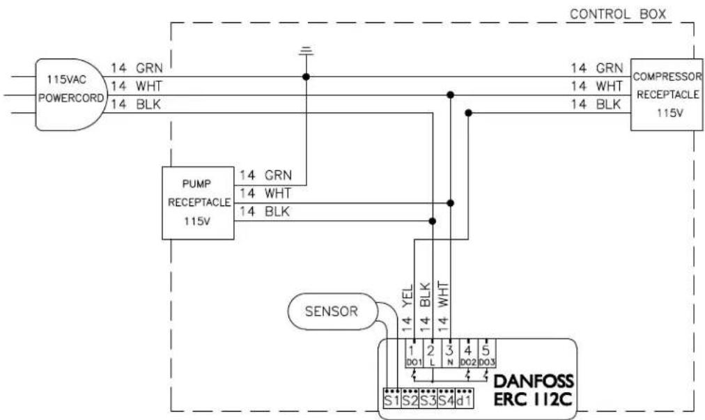
flowchart
graph TD
    A["115VAC POWERCORD"] -->|14 GRN 14 WHT 14 BLK| B["PUMP RECEPTACLE 115V"]
    B -->|14 GRN 14 WHT 14 BLK| C["CONTROL BOX"]
    C --> D["COMPRESSOR RECEPTACLE 115V"]
    E["SENSOR"] --> F["DANFOSS ERC 112C"]
    F --> G["S1 S2 S3 S4 d1"]
    F --> H["1 2 3 4 5 N DO2 DO3"]
    F --> I["14 YEL 14 BLK 14 WHT"]
    style A fill:#f9f,stroke:#333
    style B fill:#ccf,stroke:#333
    style C fill:#cfc,stroke:#333
    style D fill:#fcc,stroke:#333
    style E fill:#cff,stroke:#333
    style F fill:#ffc,stroke:#333
    style G fill:#fff,stroke:#333
    style H fill:#fff,stroke:#333
    style I fill:#fff,stroke:#333
MMPP4301-EP
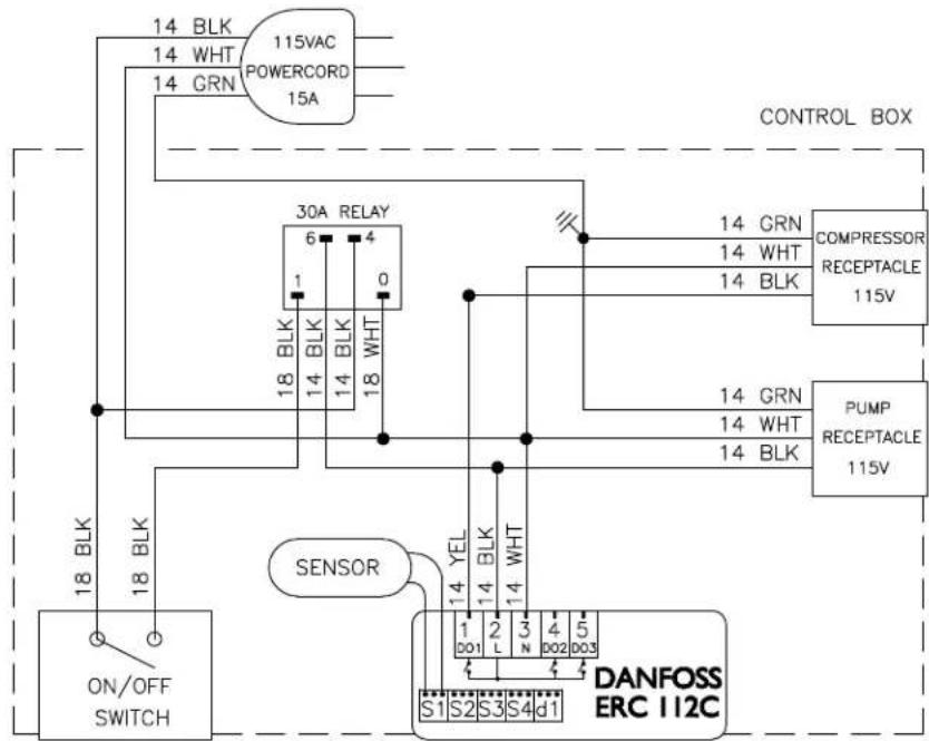
flowchart
graph TD
    A["14 BLK"] --> B["115VAC POWERCORD 15A"]
    C["18 BLK"] --> D["ON/OFF SWITCH"]
    E["14 GRN"] --> F["30A RELAY 6"]
    G["14 BLK"] --> H["14 BLK"]
    I["14 WHT"] --> J["18 BLK"]
    K["14 BLK"] --> L["18 WHT"]
    M["14 BLK"] --> N["14 BLK"]
    O["14 BLK"] --> P["14 BLK"]
    Q["14 BLK"] --> R["14 BLK"]
    S["14 BLK"] --> T["14 BLK"]
    U["14 BLK"] --> V["14 BLK"]
    W["14 BLK"] --> X["14 BLK"]
    Y["14 BLK"] --> Z["14 BLK"]
    AA["14 BLK"] --> AB["14 BLK"]
    AC["14 BLK"] --> AD["14 BLK"]
    AE["14 BLK"] --> AF["14 BLK"]
    AG["14 BLK"] --> AH["14 BLK"]
    AI["14 BLK"] --> AJ["14 BLK"]
    AK["14 BLK"] --> AL["14 BLK"]
    AM["14 BLK"] --> AN["14 BLK"]
    AO["14 BLK"] --> AP["14 BLK"]
    AQ["14 BLK"] --> AR["14 BLK"]
    AS["14 BLK"] --> AT["14 BLK"]
    AU["14 BLK"] --> AV["14 BLK"]
    AW["14 BLK"] --> AX["14 BLK"]
    AY["CONTROL BOX"] --> AZ["COMPRESSOR RECEPTACLE 115V"]
    BA["PUMP RECEPTACLE 115V"] --> BB["PUMP RECEPTACLE 115V"]
    BC["Sensor"] --> BD["YEL 1"]
    BC --> BE["YEL 2"]
    BC --> BF["YEL 3"]
    BC --> BG["YEL 4"]
    BC --> BH["YEL 5"]
    BI["DANFOSS ERC 112C"] --> BJ["S1 S2 S3 S4 d1"]
    BK["18 BLK"] --> BL["18 BLK"]
    BM["18 BLK"] --> BN["18 BLK"]
MMPP4301
MMPP4301-PKG
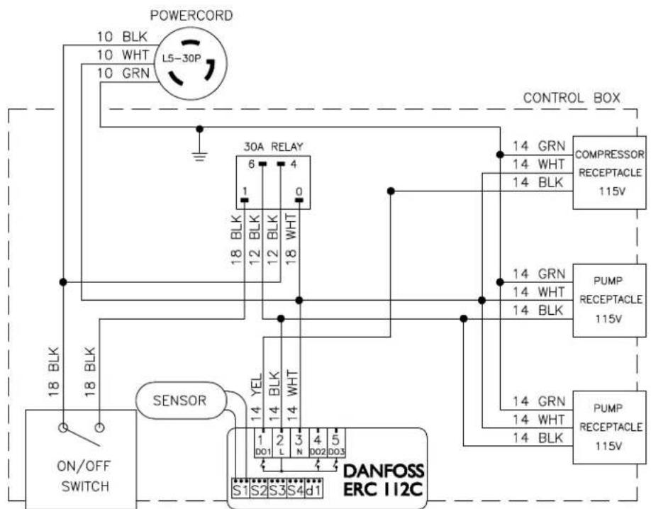
flowchart
graph TD
    A["ON/OFF SWITCH"] -->|18 BLK| B["SENSOR"]
    B -->|14 YEL| C["DANFOSS ERC I12C"]
    C -->|1 D01 L N D02 D03| D["30A RELAY"]
    D -->|6 4 0| E["CONTROL BOX"]
    E -->|14 GRN 14 WHT 14 BLK| F["COMPRESSOR RECEPTACLE 115V"]
    F -->|14 GRN 14 WHT 14 BLK| G["PUMP RECEPTACLE 115V"]
    G -->|14 GRN 14 WHT 14 BLK| H["PUMP RECEPTACLE 115V"]
    H -->|14 GRN 14 WHT 14 BLK| I["CONTROL BOX"]
    I -->|10 BLK 10 WHT 10 GRN L5-30P| J["POWERCORD"]
    J -->|10 BLK 10 WHT 10 GRN L5-30P| K["CONTROL BOX"]
    K -->|10 BLK 10 WHT 10 GRN L5-30P| L["CONTROL BOX"]
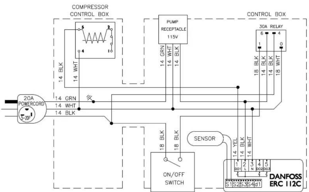
flowchart
graph TD
    A["20A POWERCORD S-20P"] -->|14 BLK| B["COMPRESSOR CONTROL BOX"]
    B --> C["PUMP RECEPTACLE 115V"]
    C --> D["30A RELAY"]
    D --> E["DANFOSS ERC 112C"]
    E --> F["ON/OFF SWITCH"]
    F --> G["SENSOR"]
    G --> H["14 BLK"]
    G --> I["14 WHT"]
    G --> J["14 BLK"]
    G --> K["18 BLK"]
    G --> L["14 BLK"]
    G --> M["14 WHT"]
    G --> N["14 BLK"]
    G --> O["18 BLK"]
    G --> P["14 BLK"]
    G --> Q["14 WHT"]
    G --> R["14 BLK"]
    G --> S["14 WHT"]
    G --> T["14 BLK"]
    G --> U["14 BLK"]
    G --> V["14 BLK"]
    G --> W["14 BLK"]
    G --> X["14 BLK"]
    G --> Y["14 BLK"]
    G --> Z["14 BLK"]
    G --> AA["14 BLK"]
    G --> AB["14 BLK"]
    G --> AC["14 BLK"]
    G --> AD["14 BLK"]
    G --> AE["14 BLK"]
    G --> AF["14 BLK"]
    G --> AG["14 BLK"]
    G --> AH["14 BLK"]
    G --> AI["14 BLK"]
    G --> AJ["14 BLK"]
    G --> AK["14 BLK"]
    G --> AL["14 BLK"]
    G --> AM["14 BLK"]
    G --> AN["14 BLK"]
    G --> AO["14 BLK"]
    G --> AP["14 BLK"]
    G --> AQ["14 BLK"]
    G --> AR["14 BLK"]
    G --> AS["14 BLK"]
    G --> AT["14 BLK"]
    G --> AU["14 BLK"]
    G --> AV["14 BLK"]
    G --> AW["14 BLK"]
MMPP4302
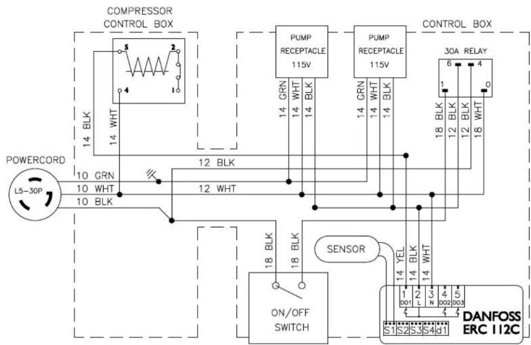
flowchart
graph TD
    A["POWERCORD L5-30P"] -->|10 GRN 10 WHT 10 BLK| B["COMPRESSOR CONTROL BOX"]
    B -->|14 BRK 14 WHT 14 BLK| C["PUMP RECEPTACLE 115V"]
    C -->|14 GRN 14 WHT 14 BLK| D["PUMP RECEPTACLE 115V"]
    D -->|14 GRN 14 WHT 14 BLK| E["30A RELAY"]
    E -->|6 BLK 12 BLK 12 BLK 18 WHT| F["DANFOSS ERC 112C"]
    F -->|14 YEL 14 BLK 14 WHT| G["SENSOR ON/OFF SWITCH"]
    G --> H["S1 S2 S3 S4 d1"]
MMPP4302-PKG
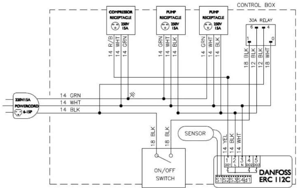
flowchart
graph TD
    A["220V/15A POWERCORD 6-15P"] -->|14 GRN| B["COMPRESSOR RECEPTACLE 250V/15A"]
    A -->|14 WHT| B
    A -->|14 BLK| C["ON/OFF SWITCH"]
    B -->|14 R/B| D["PUMP RECEPTACLE 250V/15A"]
    B -->|14 GRN| D
    B -->|14 WHT| D
    B -->|14 BLK| D
    C -->|18 BLK| E["Sensor"]
    C -->|18 BLK| E
    E --> F["14 YEL"]
    E --> G["14 BLK"]
    E --> H["14 WHT"]
    I["CONTROL BOX"] --> J["30A RELAY"]
    J --> K["6"]
    J --> L["4"]
    J --> M["1"]
    J --> N["0"]
    J --> O["18 BLK"]
    J --> P["12 BLK"]
    J --> Q["12 BLK"]
    J --> R["18 WHT"]
    S["DANFOSS ERC 112C"] --> T["1"]
    S --> U["2"]
    S --> V["3"]
    S --> W["4"]
    S --> X["5"]
    S --> Y["S1"]
    S --> Z["S2"]
    S --> AA["S3"]
    S --> AB["S4"]
    S --> AC["d1"]
MMPP4303-PKG

flowchart
graph TD
    A["220V/20A POWERCORD 6-20P"] -->|14 GRN 14 WHT 14 BLK| B["ON/OFF SWITCH"]
    B --> C["COMPRESSOR RECEPTACLE 250V 15A"]
    B --> D["PUMP RECEPTACLE 250V 15A"]
    B --> E["PUMP RECEPTACLE 250V 15A"]
    B --> F["PUMP RECEPTACLE 250V 15A"]
    B --> G["30A RELAY 6 BLK 12 BLK 12 BLK 18 BLK"]
    B --> H["DANFOSS ERC 112C"]
    I["SENSOR"] --> J["14 YEL 14 BLK 14 WHT"]
    J --> K["S1 S2 S3 S4 d1"]
    L["CONTROL BOX"] --> M["14 R/B 14 GRN 14 BLK"]
    M --> N["CONVERTIC Box"]
    style A fill:#f9f,stroke:#333
    style B fill:#ccf,stroke:#333
    style C fill:#cfc,stroke:#333
    style D fill:#cfc,stroke:#333
    style E fill:#cfc,stroke:#333
    style F fill:#cfc,stroke:#333
    style G fill:#cfc,stroke:#333
    style H fill:#fcc,stroke:#333
    style I fill:#fff,stroke:#333
    style J fill:#fff,stroke:#333
    style K fill:#fff,stroke:#333
    style L fill:#fff,stroke:#333
    style M fill:#fff,stroke:#333
    style N fill:#fff,stroke:#333
    style_O["14 R/B"] --> P["CONVERTIC Box"]
    Q["14 GRN"] --> R["CONVERTIC Box"]
    S["14 BLK"] --> T["CONVERTIC Box"]
MMPP4303-PKG-3
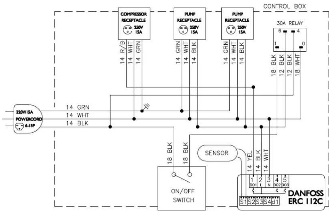
flowchart
graph TD
    A["220V/ISA POWERCORD 6-ISP"] -->|14 GRN 14 WHT 14 BLK| B["COMPRESSOR RECEPTACLE 250V/ISA"]
    B -->|14 R/B 14 WHT 14 GRN| C["PUMP RECEPTACLE 250V/ISA"]
    C -->|14 GRN 14 WHT 14 BLK| D["PUMP RECEPTACLE 250V/ISA"]
    D -->|14 GRN 14 WHT 14 BLK| E["30A RELAY"]
    E -->|1 2 3 4 5| F["DANFOSS ERC 112C"]
    B --> G["ON/OFF SWITCH"]
    C --> G
    D --> G
    G --> H["S1 S2 S3 S4 d1"]
    style A fill:#f9f,stroke:#333
    style B fill:#ccf,stroke:#333
    style C fill:#ccf,stroke:#333
    style D fill:#ccf,stroke:#333
    style E fill:#cfc,stroke:#333
    style F fill:#fcc,stroke:#333
    style G fill:#cff,stroke:#333
    style H fill:#ffc,stroke:#333
MMPP4305-PKG
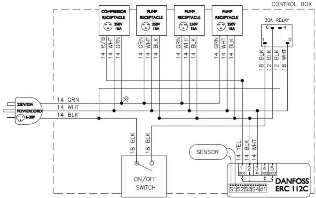
flowchart
graph TD
    A["220V/20A POWERCORD 6-20P"] -->|14 GRN 14 WHT 14 BLK| B["COMPRESSOR RECEPTACLE 250V ISA"]
    B -->|14 R/B 14 WHT 14 GRN| C["PUMP RECEPTACLE 250V ISA"]
    C -->|14 GRN 14 WHT 14 BLK| D["PUMP RECEPTACLE 250V ISA"]
    D -->|14 GRN 14 WHT 14 BLK| E["PUMP RECEPTACLE 250V ISA"]
    E -->|14 GRN 14 WHT 14 BLK| F["30A RELAY 6 BLK 18 BLK 12 BLK 12 BLK 18 WHT"]
    F --> G["DANFOSS ERC I12C"]
    G --> H["SENSOR"]
    H --> I["ON/OFF SWITCH"]
    I --> J["14 YEL 14 BLK 14 WHT"]
    J --> K["S1 S2 S3 S4 d1"]
    K --> L["CONTROL BOX"]
MMPP4305-PKG-3
WARRANTY
All power packs carry a full warranty against defects in material and workmanship for a period of eighteen (18) months from date of sale. Defective parts, subject to Micro Matic inspection, will be replaced or repaired for ninety (90) days on a no charge basis. The compressor has a standard five (5) year warranty. All loss of sales must be borne by the purchaser.
Warranty Claims Procedure:
Purchaser shall notify Micro Matic of any defect discovered in the Product during the Warranty Period, and obtain a return authorization number. Purchaser must ship the Product per Micro Matic's instruction. After receipt of the Product, Micro Matic shall, at its option, repair (or authorize the repair of), or replace or refund the purchase price for the Products found by Micro Matic to be defective. Micro Matic's determination of defects is final. Failure by Purchaser to give notice of claims of breach of warranty within the Warranty Period shall be deemed an absolute and unconditional waiver of Purchaser's claim for such defects. Products repaired or replaced during the Warranty Period shall be covered by the foregoing warranties for the remainder of the original Warranty Period or ninety (90) days from the date of delivery of the repaired or replaced Products, whichever is longer.
ALL REPAIRS MUST BE FIRST AUTHORIZED BY MICRO MATIC PER THE ABOVE PROCEDURE. UNAUTHORIZED REPAIRS WILL NOT BE REIMBURSED BY MICRO MATIC UNDER ANY CIRCUMSTANCES.
Micro Matic is not responsible for parts damaged from factors including, but not limited to any part that has been subject to misuse, neglect, alteration, accident, unauthorized service, abuse, or to any damage caused by transportation. This warranty does not cover items subject to normal wear and tear (gaskets, seals, o-rings, etc.).
Purchaser Responsibility:
Except as expressly provided in this Agreement, Purchaser assumes all other responsibility for any loss, damage, or injury to persons or property arising out of, connected with, or resulting from the use of Products, either alone or in combination with other products or components. In no event will Micro Matic be responsible for incidental, consequential or punitive damages of any kind, including without limitation, claims for loss of beer, loss of gas or loss of sales.
Other Warranties Disclaimed:
These are the sole and exclusive warranties and conditions given by Micro Matic with respect to the products and services and are in lieu of and exclude all other warranties or conditions, express or implied, arising by operation of law or otherwise, including without limitation, warranties of merchantability, fitness for a particular purpose and non-infringement, whether or not the purpose or use has been disclosed to Micro Matic in specifications, drawings or otherwise, and whether or not Micro Matic's products are specifically designed and/or manufactured by Micro Matic for purchaser's use or purpose.
Limitation of Remedy:
Purchaser's sole and exclusive remedy for breach of any warranty or condition under this Article IV shall be limited to the repair, correction or replacement, or refund of the purchase price paid in respect of the defective Products, unless the claim falls under the provisions of Section 6.2, in which case Purchaser may also claim damages in accordance with the terms of Section 6.2.
- Power Pack Service Manual
- TABLE OF CONTENTS
- INSTALLATION AND OPERATION
- PLACEMENT
- 75' UNIT INSTALLATION STEPS
- 125', 250', 350' AND 500' UNITS INSTALLATION STEPS
- MAINTENANCE
- ELECTRONIC TEMPERATURE CONTROL WITH DISPLAY
- CHANGING A GLYCOL PUMP 75' UNIT
- 125', 250', 350' AND 500' UNITS
- Note: A pinch off tool is required to complete this repair
- REPLACING MOTOR 125', 250', 350' AND 500' UNITS
- REPLACING THERMOSTAT ALL UNITS
- TROUBLESHOOTING
- TYPICAL SPARE PARTS
- WARRANTY
- Warranty Claims Procedure:
- ALL REPAIRS MUST BE FIRST AUTHORIZED BY MICRO MATIC PER THE ABOVE PROCEDURE. UNAUTHORIZED REPAIRS WILL NOT BE REIMBURSED BY MICRO MATIC UNDER ANY CIRCUMSTANCES.
- Purchaser Responsibility:
- Other Warranties Disclaimed:
- Limitation of Remedy:
Brand : Micro Matic
Model : MMPP4301-PKG
Category : Uncategorized