CSL-14 - Blender Citronic - Free user manual and instructions
Find the device manual for free CSL-14 Citronic in PDF.


| Product Type | Passive Mixing Console |
| Model | CSL-14 |
| Brand | Citronic |
| Dimensions (H x W x D) | 475 x 320 x 107 mm |
| Weight | 4.50 kg |
| Power Supply | 230 V AC, 50/60 Hz |
| Power Consumption | 25 W (max) |
| Fuse Rating | T1A (5 x 20 mm) |
| Inputs (Mic/Line) | 10 x balanced XLRF/TRS jack |
| Inputs (Stereo Line) | 2 x L+R TRS jack (ST1, ST2) |
| Outputs (Main) | 2 x balanced XLR (L/R) |
| Auxiliary Outputs | 1 x AUX SEND (unbalanced jack), 1 x FX/AUX SEND (unbalanced jack) |
| Headphone Output | 6.3 mm stereo jack, 30–600 Ω |
| 2-Track Input/Output | 2 x RCA in, 2 x RCA out |
| EQ per Channel | High: 12 kHz ±15 dB shelving; Mid: 2.5 kHz ±15 dB bandpass; Low: 80 Hz ±15 dB shelving |
| Master Graphic EQ | 7-band stereo: 63, 160, 400, 1k, 2.5k, 6.3k, 16 kHz (±12 dB) |
| Built-in Effects | 16-program 24-bit DSP (40 kHz sampling) |
| Phantom Power | +48 V, globally switchable to all XLR inputs |
| Frequency Response | 20 Hz – 30 kHz (±0.5 dB) |
| THD+N | < 0.01% (channel to main out) |
| Input Impedance | 2 kΩ (balanced mic), 10 kΩ (balanced line) |
| Output Impedance | < 75 Ω |
| Cleaning Instructions | Use soft dry or slightly damp cloth; avoid solvents. |
| Safety Notes | Do not expose to rain/moisture; no user-serviceable parts; must be earthed. |
Frequently Asked Questions - CSL-14 Citronic
User questions about CSL-14 Citronic
0 question about this device. Answer the ones you know or ask your own.
Ask a new question about this device
Download the instructions for your Blender in PDF format for free! Find your manual CSL-14 - Citronic and take your electronic device back in hand. On this page are published all the documents necessary for the use of your device. CSL-14 by Citronic.
USER MANUAL CSL-14 Citronic
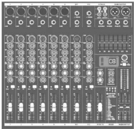
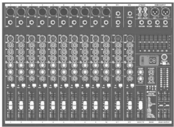
Version 2.1

Caution: Please read this manual carefully before operating
Damage caused by misuse is not covered by the warranty
Introduction
Thank you for choosing a CSP/CSL mixing console as part of your professional sound system. This product has been developed to provide a wide range of facilities for professional and reliable sound reinforcement. Please read and keep this manual to achieve the best results from your purchase and avoid damage through misuse.
Package Contents
• CSP powered or CSL passive mixing console
- Mains lead(s)
- User manual
If you find any accessory is missing or the product has arrived with any problems, please contact your retailer at once. This product contains no user-serviceable parts, so make no attempt to try to fix or modify this item yourself as this will invalidate the warranty. We recommend you keep the original package and proof of purchase for any possible replacement or return issues.
Warning
To prevent the risk of fire or electric shock, do not expose any of the components to rain or moisture. Avoid impact or heavy vibration to any of the components.
No user serviceable parts inside - refer servicing to qualified service personnel.
Safety
- Please observe the following warning conventions

CAUTION: RISK OF ELECTRIC SHOCK DO NOT OPEN


This symbol indicates that dangerous voltage constituting a risk of electric shock is present within this unit

This symbol indicates that there are important operating and maintenance instructions in the literature accompanying this unit.
• Ensure that the correct mains lead is used with adequate current rating and mains voltage is as stated on the unit
- Avoid ingress of water or particles into any part of the housing. If liquids are spilled on the console, stop using immediately, allow the unit to dry out and have checked by qualified personnel before further use
• Do not cover or obstruct cooling vents

Warning: this unit must be earthed
Placement
- Keep the console out of direct sunlight and away from heat sources.
- Do not place heavy objects on top of the control surface
- If rack-mounting, use the correct rack-ears and ensure adequate support for the weight of the product.
- Allow adequate space for air-flow and keep the console away from damp or dusty environments.
Cleaning
• Use a soft dry or slightly damp cloth top clean surfaces of the console
• A soft brush can be used to clear debris from between controls without damaging them
- To avoid damage, do not use solvents to clean the components
Console layout
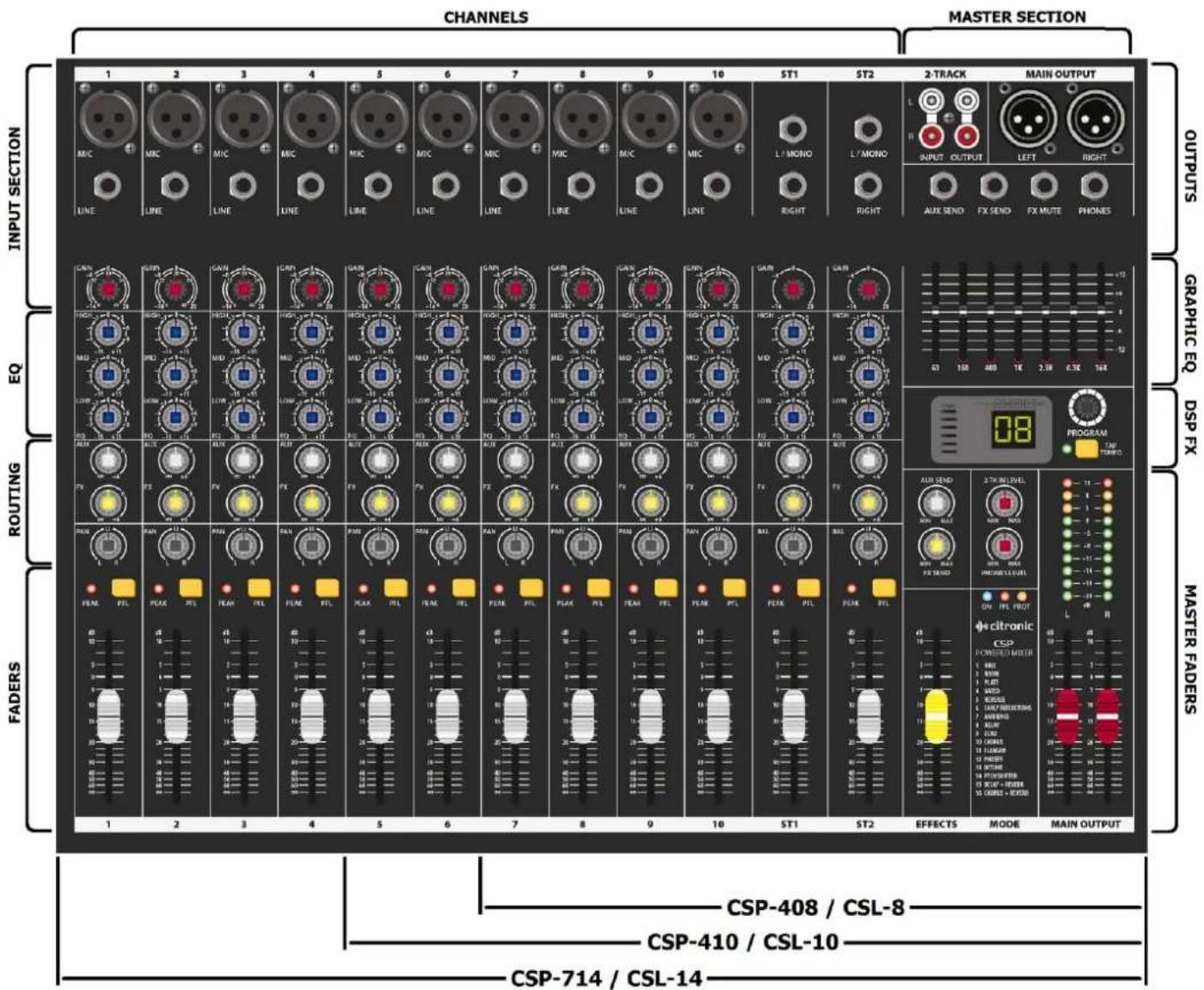
Each CSP/CSL mixing console has comprehensive input and output sections which can be split further into various stages of processing and routing. All preamps have studio grade, low noise architecture for the cleanest possible path throughout the signal chain. The input stages are repeated across each channel of the console, which simplifies operation and enables quick and easy location of various controls. The following pages of this manual are divided up into these stages to explain the details and function of each control.
Mic/Line Input Section
Channel inputs and inserts are provided as XLR and/or 6.3mm jack sockets. The connections for these inputs are assigned as follows.
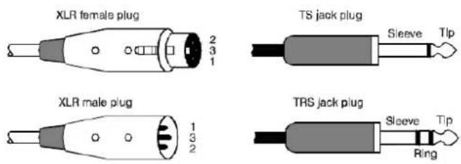
- MIC input Connect a balanced microphone to this XLRF input. An unbalanced microphone can be connected provided that +48V phantom power is not used. Wired as follows.
| Balanced | Pin 1 = Ground | Pin 2 = Signal + | Pin 3 = Signal - |
| Unbalanced | Pin 1 = Ground | Pin 2 = Signal + | Pin 3 = Ground |
- LINE input Connect balanced or unbalanced line level signals to this 6.3mm TRS jack input. Wired as follows.
| Balanced | Tip = Signal + | Ring = Signal - | Sleeve = Ground |
| Unbalanced | Tip = Signal + | - | Sleeve = Ground |
- L/MONO input For stereo channels, connect line level signals to 2 TRS jack inputs for Left and Right. If the input is mono, only connect to the L/MONO input, which will feed to both Left and Right. Wired as follows.
| Balanced | Tip = Signal + | Ring = Signal - | Sleeve = Ground |
| Unbalanced | Tip = Signal + | - | Sleeve = Ground |
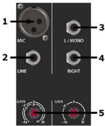
- GAIN control This control trims the input signal to the optimum level for the channel strip circuitry. Too low a signal level can result in a weak signal-to-noise ratio and too high can result in overload and distortion in the signal output. The PEAK LED next to the channel fader will give an indication of the signal level. Ideally, the Gain rotary control should be adjusted so that the loudest passages of the input signal (e.g. bass drum beats) will just momentarily trigger the CLIP LED. Anything longer than a momentary flicker of the CLIP LED means that the Gain should be reduced. Using the PFL button further down the channel strip gives a more detailed view of the channel level on the main VU LEDs.
EQ Section
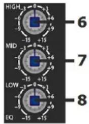
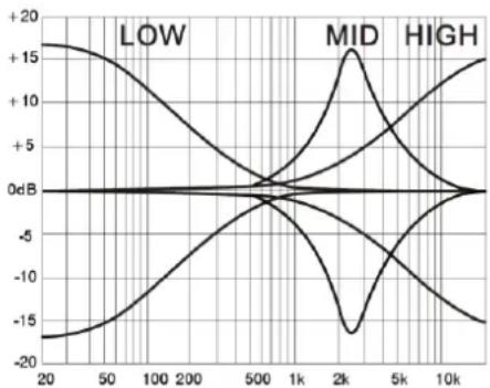
- HIGH This control can boost or cut the high frequencies (centre 12kHz) by ±15dB (12 o'clock position is zero)
- MID This control can boost or cut the mid frequencies (centre 2.5kHz) by ±15dB (12 o'clock position is zero)
- LOW This control can boost or cut the low frequencies (centre 80Hz) by ±15dB (12 o'clock position is zero)
line
| Frequency | LOW | MID | HIGH | | --------- | ---- | ---- | ---- | | 20 | +15 | 0dB | -15 | | 50 | +10 | 0dB | -10 | | 100 | +5 | 0dB | -5 | | 200 | 0 | 0dB | 0 | | 500 | -5 | 0dB | -5 | | 1k | -10 | 0dB | -10 | | 2k | -15 | +15 | -15 | | 5k | -10 | +10 | -10 | | 10k | -5 | +5 | -5 |Channel Routing
-
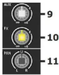
AUX This control governs the amount of signal from the channel routed to the AUX SEND or auxiliary output to external equipment. (This control is post-fader - i.e. the signal routed to AUX SEND is also affected by the channel fader level)
-
FX This control governs the amount of signal from the channel routed to the DSP effects engine. If a jack is connected to the FX SEND connector (see 37 below), this will operate as an extra AUX output (This control is post-fader - i.e. the signal routed to AUX SEND is also affected by the channel fader level)
-
PAN/BAL This control adjusts the amount of signal from the channel fed to Left or Right outputs. This varies the point in the stereo field that the signal appears. For ST1 and ST2 channels, the PAN control is replaced with a BAL control for Left/Right balance.
Channel Faders
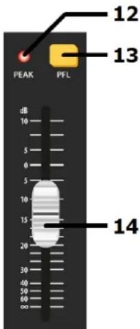
- PEAK LED Indicator showing when signal reaches maximum level and clipping.
- PFL Pre-Fader Listen sends the channel signal direct to monitoring. This means that the channel signal is shown on the main VU LEDs. Also, the signal is routed directly to the headphones output. This allows the particular channel signal to be checked. If many PFLs or AFLs are selected, all are routed to monitoring.
- Channel fader 60mm fader to adjust the channel level to the master output. A dB scale is provided to show the level of boost or cut.
Graphic Equalizer
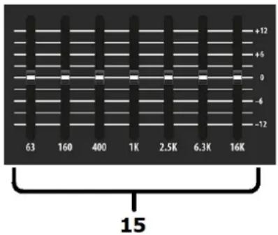
The main EQ is a stereo 7-band graphic equalizer, offering refined audio spectrum shaping and feedback control for live mic situations.
- EQ sliders.
Each slider controls a boost or cut of up to 12dB centred at the specified frequency.
DSP Effects Engine
CSP and CSL series mixers each have an internal 24-bit DSP processor for audio effects, as detailed on the DSP Table (on the following page)
-
6-segment LED Indicates overall input level to DSP
-
Program display Indicates selected program (see table on next page)
-
TAP Press once to switch the rotary control (27) to PARAMETER 2.
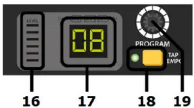
Tap the TAP button rhythmically more than twice to set a tempo for time effects An LED to the left of the TAP switch flashes to indicate time intervals
- PROGRAM Turn this rotary encoder to select a program. /PARAMETER The numerical display will flash the selected program number.
Press the encoder to confirm the selection, the display will stop flashing & the selected program will be active.
Press the encoder again and a dot will appear in the display indicating PARAMETER 1. Turning the encoder will change PARAMETER 1 for the selected program as detailed in the DSP Table on the following page.
Pressing the TAP button (26) will switch to PARAMETER 2 and then turning the encoder will change PARAMETER 2 for the selected program.
These parameter changes are stored for when the program is selected in future.
DSP EFFECTS TABLE
| PROGRAM | EFFECT | PARAMETER 1 | MIN | MAX | PARAMETER 2 | MIN | MAX | TAP |
| 01 | Hall | Reverb time | 01 (approx 1 second) | 10 (approx 8 seconds) | Brilliance | OFF | ON | LED on/off |
| 02 | Room | Reverb time | 01 (approx 0.5 second) | 10 (approx 4 seconds) | Brilliance | OFF | ON | LED on/off |
| 03 | Plate | Reverb time | 01 (approx 0.5 second) | 10 (approx 5 seconds) | Brilliance | OFF | ON | LED on/off |
| 04 | Gated | Reverb time | 01 (approx 0.1 second) | 10 (approx 1 second) | Brilliance | OFF | ON | LED on/off |
| 05 | Reverse | Reverb time | 01 (approx 0.1 second) | 10 (approx 1 second) | Brilliance | OFF | ON | LED on/off |
| 06 | Early Reflections | Room size | 01 (small) | 10 (very large) | Brilliance | OFF | ON | LED on/off |
| 07 | Ambience | Area size | 01 (small) | 10 (very large) | Brilliance | OFF | ON | LED on/off |
| 08 | Delay | Repeats | 01 (no regeneration) | 20 (max regeneration) | Delay Time (bpm) | 07 (72bpm) | 60 (600bpm) | Blinking BPM Tempo |
| 09 | Echo | Repeats | 01 (no regeneration) | 40 (max regeneration) | Delay Time (bpm) | 07 (72bpm) | 60 (600bpm) | Blinking BPM Tempo |
| 10 | Chorus | Depth | 01 (1%) | 99 (99%) | Mod Speed bpm | 02 (24bpm) | 48 (480bpm) | Blinking Mod Speed |
| 11 | Flanger | Depth | 01 (1%) | 99 (99%) | Mod Speed bpm | 02 (24bpm) | 48 (480bpm) | Blinking Mod Speed |
| 12 | Phaser | Depth | 01 (1%) | 99 (99%) | Mod Speed bpm | 02 (24bpm) | 48 (480bpm) | Blinking Mod Speed |
| 13 | Detune | Depth | 01 (1%) | 99 (99%) | 2nd voice delay | 05 (5ms) | 50 (50ms) | LED on/off |
| 14 | Pitch Shift | Semitone steps | -12 (1 octave down) | +12 (1 octave up) | Detune | OFF (0%) | ON (25%) | LED on/off |
| 15 | Delay + Rev | Ratio | -9 (90% Dly / 10% Rev) | 9 (10% Dly / 90% Rev) | Delay time (bpm) | 11 (116bpm) | 60 (600bpm) | Blinking BPM Tempo |
| 16 | Chorus + Rev | Ratio | -9 (90% Cho / 10% Rev) | 9 (10% Cho / 90% Rev) | Reverb time | 12 (1.2sec) | 24 (2.4secs) | LED on/off |
Master Output Section
-
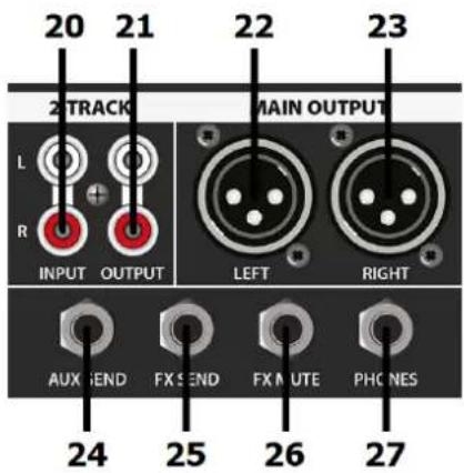
2 TRACK INPUT Left + Right RCA input for connecting a playback device (e.g. CD or mp3) governed by the 2TK IN LEVEL rotary control. This output is pre-master-fader. (i.e. unaffected by main Left + Right faders)
-
2 TRACK OUT Left + Right RCA connection for main mix output to a recording device. This output is pre-master-fader
-
MAIN L OUTPUT Balanced XLR output for main Left out
-
MAIN R OUTPUT Balanced XLR output for main Right out
-
AUX SEND Unbalanced jack output from AUX SEND routes. The mix is governed by AUX levels from each channel.
-
FX / AUX SEND Unbalanced jack output from FX SEND routes. Overrides internal DSP effects when a jack is connected. The mix is governed by FX levels from each channel.
-
FX MUTE Footswitch jack to mute FX. Connect a non-latching footswitch here to mute or un-mute the FX SEND signal.
-
PHONES Stereo headphones 6.3mm jack output
Master Routing Section
-
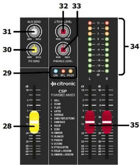
EFFECTS fader Controls the level of FX to main mix
-
Status LEDs Indicate Power On, PFL activated & Amplifier Protect (CSP only) statuses
-
FX SEND Overall level control of signals routed to the FX Send buss, either for internal DSP or FX Send output (20). When using the internal DSP, it is important to observe the LED level meter (16) on the DSP section and if the signal is clipping, reduce the FX SEND level accordingly.
-
AUX SEND Overall level control of signals routed to the AUX Send output (19)
-
2-TK LEVEL Level control for the 2-track RCA inputs
-
PHONES LEVEL Level control for headphones output. Pressing this button reverses this by routing the output of the PC or Mac back to the PC interface for playback.
-
VU meters Dual 10-segment LED ladders indication output level (or channel level if PFL is active)
-
Master faders Controls for main Left & Right output levels
Rear Panel
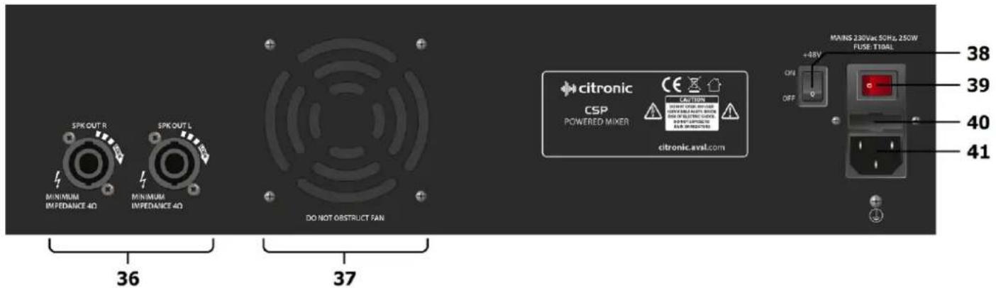
- Speaker outs (CSP only)
- Cooling fan vent (CSP only)
- +48V switch
- Power switch
- Fuse holder
- IEC mains inlet
Left & Right twist-lock SPK connectors for speaker connection (4Ω min.)
Ventilation for internal cooling fan. Do not obstruct or cover.
Rocker switch to enable +48V phantom power to all XLR inputs.
Illuminated rocker switch for main power on/off.
Integral holder for 5 x 20mm fuse. Replace only with type indicated.
Mains connection. Ensure voltage as indicated. Use IEC lead supplied.
Powering up
Connect the IEC inlet (40) to mains power using the supplied mains lead. In case of the fuse blowing, replace only with the type indicated. If the fuse is repeatedly blowing, refer to qualified service personnel.
The illuminated rocker switch activates mains power to the unit.
Phantom power
In addition to the mains power switch, the rear panel has an additional rocker switch which when switched on, enables +48V phantom power to the XLR input connectors. This is mainly used for condenser microphones which do not have an internal battery or to remotely power D.I. boxes for patching instruments directly into the mixer.
Connecting Speakers (CSP only)
When connecting speakers to the CSP-series mixers, ensure that the combined load for each output (left or right) is no lower than 4 Ohms (4Ω). To make sure of this, check the speaker manufacturer's information.
If connecting more than one speaker to an output channel, observe the following calculation method.
$$ \frac {1}{\text { Impedance of speaker } 1} + \frac {1}{\text { Impedance of speaker } 2} = \frac {1}{\text { Total Impedance }} $$
Note: normally, speakers will be connected in parallel by connecting a speaker lead from one to another.
Most PA and sound reinforcement speakers are 8 , so we consider that 1/8 + 1/8 = 1/4 .
Therefore, when connecting 2 x 8Ω speakers together in parallel, the resulting total load is 4Ω.
It is also important to ensure that the power delivered to the speakers will not overload them.
When connecting 2 × 8 speakers together on one channel, each speaker will equally receive half of the output of that channel.
Specifications
| Model | CSP-408 | CSL-8 | CSP410 | CSL-10 | CSP714 | CSL-14 | |
| Power supply | 230Vac, 50/60Hz (IEC) | ||||||
| Fuse rating | T10A | T1A | T10A | T1A | T15A | T1A | |
| Power consumption (max) | 600W | 25W | 600W | 25W | 1000W | 25W | |
| Output power RMS @ 4Ω | 2 x 200W | N/A | 2 x 200W | N/A | 2 x 350W | N/A | |
| Output power RMS @ 8Ω | 2 x 130W | N/A | 2 x 130W | N/A | 2 x 230W | N/A | |
| Inputs mic/line | 4 x bal. XLRF/TRS jack | 6 x bal. XLRF/TRS jack | 10 x bal. XLRF/TRS jack | ||||
| Inputs stereo line | 2 x L+R jack | ||||||
| Input level | +24dBu | ||||||
| Output level | +26dBu | ||||||
| Sensitivity | -60 to +14dBu (mic), -40 to +14dBu (line), | ||||||
| Frequency response | 20Hz - 30kHz (+/-0.5dB) | ||||||
| CMRR | >74dB typical @1kHz (mic) | ||||||
| THD+N | <0.01% (channel to main out) | ||||||
| Crosstalk | >85dB (fader mute), >82dB (channel) | ||||||
| Input impedance | 2kΩ (balanced mic), 10kΩ (balanced line) | ||||||
| Output impedance | <75Ω | ||||||
| Noise rms:22Hz-22kHz | -122dBu (EIN), -82dBu (mix) | ||||||
| Phantom power | +48V globally switchable to all XLR inputs | ||||||
| Headphone output | 6.3mm stereo jack, 30-600Ω | ||||||
| 2-track | 2 x RCA in & out (-2dBu) | ||||||
| EQ | High | 12kHz ±15dB shelving | |||||
| Mid | 2.5kHz ±15dB band pass | ||||||
| Low | 80Hz ±15dB shelving | ||||||
| Master graphic EQ bands | 63, 160, 400, 1k, 2.5k, 6.3k, 16kHz | ||||||
| Effects | 16 program, 24-bit DSP, 40khz | ||||||
| Headphone output | Stereo 6.3mm jack (30-600 Ohms recommended) | ||||||
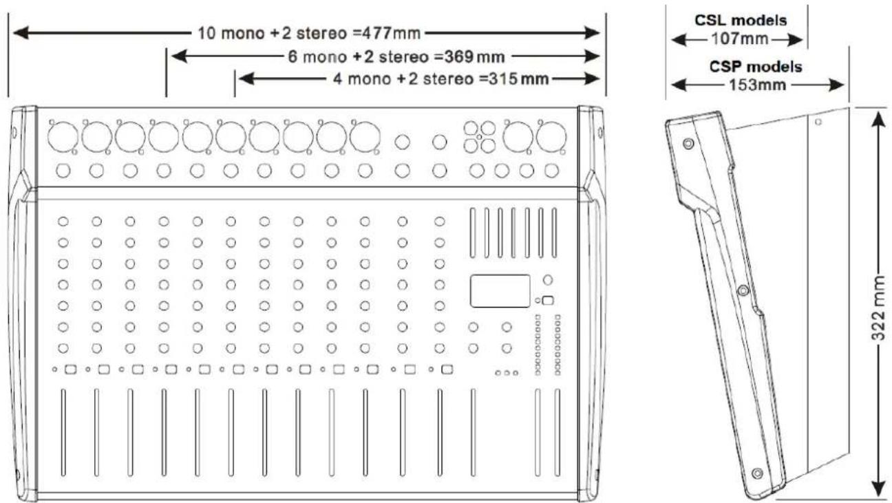
| Console dimensions (H x W) | 310 x 320mm | 360 x 320mm | 475 x 320mm | ||||
| Depth | 153mm | 107mm | 153mm | 107mm | 153mm | 107mm | |
| Weight | 6.80kg | 3.00kg | 7.35kg | 3.50kg | 10.40kg | 4.50kg | |
CSP & CSL-series User Manual
Troubleshooting
| No power "ON" LED on control panel | Ensure mains outlet voltage is correct for the unit |
| Use power lead supplied with the unit and check condition is OK | |
| Check power is switched on at the rear panel | |
| Check IEC fuse – if blowing fuses, refer to qualified service personnel | |
| Power LED is on but no other LEDs and no output | Check input signals and condition of connection leads |
| Check GAIN is not too low on channel input(s) | |
| Check channel fader, GAIN and EQ controls are not turned fully down | |
| Check MASTER faders are not fully down | |
| When using condenser microphones, use an external phantom power unit | |
| Check that PFL buttons are all switched out | |
| Check that all Graphic EQ sliders are not fully down | |
| Power light and VU LEDs lighting but no main or speaker output | Check that Main L+R outputs are not muted |
| Check MASTER faders are not fully down | |
| Check speakers are functional, and leads are OK and connected properly | |
| "PROT" indicator is lit and no output (CSP only) | Protect mode – switch off power immediatelyDisconnect speakers and switch power back on to the unit.If unit powers up OK and PROT light is off, refer speakers to qualified service personnel. If PROT is still lit, switch off power and refer CSP unit and speakers for checking by qualified service personnel. |
| VU LEDs do not show MAIN output levels | Check that PFL buttons are all switched out |
| Output is very loud or distorted | Check level of input signal is not too high |
| Reduce channel GAIN and EQ settings | |
| Reduce channel and MAIN faders levels | |
| Ensure Hi-Z line level input(s) not connected via XLR | |
| Check AUX and EFFECT level controls and reduce if necessary | |
| Output is working but at very low level | Check input audio source level is not too low |
| Ensure low impedance mic or line signal is not connected via jack | |
| Increase channel GAIN control and EQ settings if turned down | |
| Increase channel and MAIN faders levels | |
| Feedback(loud squealing or howling from mics) | Face microphone away from speakers and monitors |
| Reduce channel GAIN level and EQ level(s) | |
| Reduce AUX and/or EFFECT levels | |
| Reduce channel and/or MAIN fader levels |
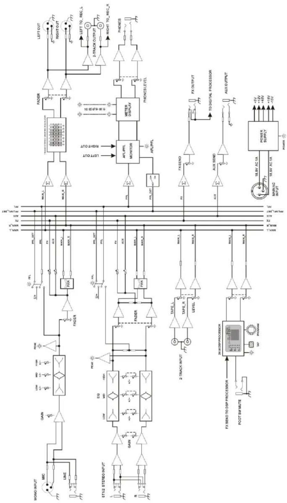
flowchart
graph TD
    A["MONO INPUT"] --> B["MIC"]
    B --> C["LINE"]
    C --> D["GAIN"]
    D --> E["6T1/2 STEREO INPUT"]
    E --> F["R"]
    F --> G["GAIN"]
    G --> H["MIN_L"]
    H --> I["FADER"]
    I --> J["PAN"]
    J --> K["PTL"]
    K --> L["FTR"]
    L --> M["MIN_R"]
    M --> N["MIN_L"]
    N --> O["MIN_OUT"]
    O --> P["FADER"]
    P --> Q["PAN"]
    Q --> R["FTR"]
    R --> S["PAN"]
    S --> T["MIN_L"]
    T --> U["FTR"]
    U --> V["PAN"]
    V --> W["MIN_OUT"]
    W --> X["FTR"]
    X --> Y["PAN"]
    Y --> Z["FTR"]
    Z --> AA["PAN"]
    AA --> AB["FTR"]
    AB --> AC["PAN"]
    AC --> AD["FTR"]
    AD --> AE["PAN"]
    AE --> AF["PAN"]
    AF --> AG["FTR"]
    AG --> AH["PAN"]
    AH --> AI["FTR"]
    AI --> AJ["PAN"]
    AJ --> AK["FTR"]
    AK --> AL["PAN"]
    AL --> AM["FTR"]
    AM --> AN["PAN"]
    AN --> AO["PAN"]
    AO --> AP["FTR"]
    AP --> AQ["PAN"]
    AQ --> AR["FTR"]
    AR --> AS["PAN"]
    AS --> AT["FTR"]
    AT --> AU["PAN"]
    AU --> AV["FTR"]
    AV --> AW["PAN"]
    AW --> AX["FTR"]
    AX --> AY["PAN"]
    AY --> AZ["FTR"]
    AZ --> BA["PAN"]
    BA --> BB["FTR"]
    BB --> BC["FTR"]
    BC --> BD["PAN"]
    BD --> BE["FTR"]
    BE --> BF["PAN"]
    BF --> BG["FTR"]
    BG --> BH["PAN"]
    BH --> BI["FTR"]
    BI --> BJ["PAN"]
    BJ --> BK["FTR"]
    BK --> BL["PAN"]
    BL --> BM["FTR"]
    BM --> BN["PAN"]
    BN --> BO["FTR"]
    BO --> BP["PAN"]
    BP --> BQ["FTR"]
    BQ --> BR["PAN"]
    BR --> BS["FTR"]
    BS --> BT["PAN"]
    BT --> BU["FTR"]
    BU --> BV["PAN"]
    BV --> BW["FTR"]
    BW --> BX["PAN"]
    BX --> BY["PAN"]
    BY --> BZ["FTR"]
    BZ --> CA["PAN"]
    CA --> CB["FTR"]
    CB --> CC["PAN"]
    CC --> CD["FTR"]
    CD --> CE["PAN"]
    CE --> CF["FTR"]
    CF --> CG["PAN"]
    CG --> CH["FTR"]
    CH --> CI["PAN"]
    CI --> CJ["FTR"]
    CJ --> CK["PAN"]
    CK --> CL["FTR"]
    CL --> CM["PAN"]
    CM --> CN["FTR"]
    CN --> CO["PAN"]
    CO --> CP["FTR"]
    CP --> CQ["PAN"]
    CQ --> CR["FTR"]
    CR --> CS["PAN"]
    CS --> CT["FTR"]

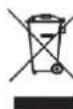
Disposal: The "Crossed Wheelie Bin" symbol on the product means that the product is classed as Electrical or Electronic equipment and should not be disposed with other household or commercial waste at the end of its useful life. The goods must be disposed of according to your local council guidelines
- Version 2.1
- Introduction
- Package Contents
- Warning
- Safety
- CAUTION: RISK OF ELECTRIC SHOCK DO NOT OPEN
- Warning: this unit must be earthed
- Placement
- Cleaning
- Mic/Line Input Section
- EQ Section
- Channel Routing
- Channel Faders
- Graphic Equalizer
- DSP Effects Engine
- Master Output Section
- Master Routing Section
- Rear Panel
- Powering up
- Phantom power
- Connecting Speakers (CSP only)
Brand : Citronic
Model : CSL-14
Category : Blender