
ARC10E - Electric heating DIMPLEX - Free user manual and instructions
Find the device manual for free ARC10E DIMPLEX in PDF.


| Product Type | Electric Convector Heater |
| Brand | Dimplex |
| Model | ARC10E |
| Power Output | 1000 W |
| Heating Technology | Convection |
| Supply Voltage | 220-240 V ~ 50 Hz |
| Dimensions (H x W x D) | 400 x 450 x 100 mm |
| Weight | 3.5 kg |
| Thermostat Control | Electronic with adjustable temperature setting |
| Heat Settings | 2 (low and high) |
| Frost Protection | Yes, automatically maintains 7°C |
| Overheat Protection | Yes, thermal cut-off switch |
| Tip-over Protection | Yes, automatic shut-off when tilted |
| Material | Steel body with powder coating |
| Colour | White |
| Mounting | Floor standing or wall mounted (brackets included) |
| Power Cord Length | 1.5 m |
| Noise Level | < 30 dB (silent operation) |
| Room Size Recommendation | Up to 20 m² (well-insulated) |
| Energy Efficiency Class | B (expected) |
| Cleaning Instructions | Wipe with a dry or slightly damp cloth; do not use abrasive cleaners |
| Maintenance | Check and clean air inlet/outlet regularly |
| Indoor Use Only | Yes |
| Certifications | CE, RoHS |
Frequently Asked Questions - ARC10E DIMPLEX
User questions about ARC10E DIMPLEX
0 question about this device. Answer the ones you know or ask your own.
Ask a new question about this device
Download the instructions for your Electric heating in PDF format for free! Find your manual ARC10E - DIMPLEX and take your electronic device back in hand. On this page are published all the documents necessary for the use of your device. ARC10E by DIMPLEX.
USER MANUAL ARC10E DIMPLEX
natural_image
3D rendering of a cylindrical object with a flat top and bottom surface (no text or symbols)ARC10E, ARC15E, ARC20E, ARC10W, ARC15W, ARC20W, ARC10A, ARC15A & ARC20A
1
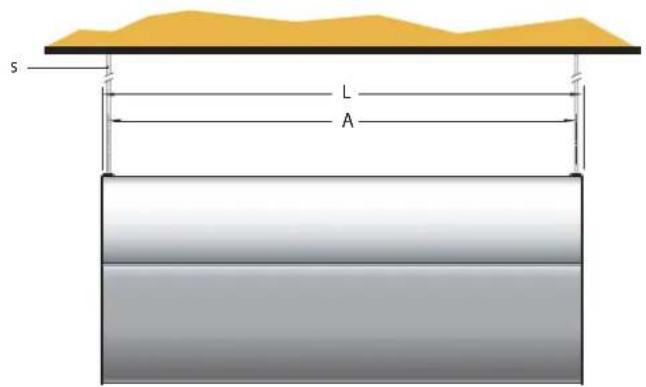
| L | W | H | |||||
| ARC10 E/W/A | 1106 | 360 450 | 1060 | 175 | |||
| ARC15 E/W/A | 1606 | 360 450 | 1560 | 175 | |||
| ARC20 E/W/A | 2212 | 360 450 | 1060 | 175 | |||
A
2
natural_image
Technical diagram showing a cylindrical component with a dashed circular inset view of a metal bracket with dimension labels (115 and 270), no readable text or symbols present.3
4
natural_image
Technical diagram of an internal appliance or housing with visible internal components and labeled parts (a), no readable text or symbols present.5
natural_image
Technical diagram of an air conditioner unit with internal cooling system and labeled component 'a' (no text or symbols beyond label)6
ARC 'E'

7
ARC 'W' & ARC 'A'
8
natural_image
3D diagram of a mechanical component with labeled parts (a and b), no readable text or symbols beyond labels⑨
natural_image
3D rendering of a cylindrical industrial component with heat dissipation zones and downward arrows indicating flow or stress (no text or symbols)IMPORTANT SAFETY ADVICE
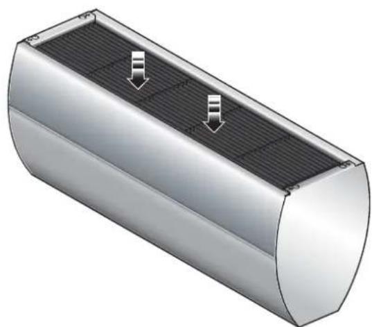
DO NOT COVER OR OBSTRUCT the air inlet or outlet grille. ENSURE THE APPLIANCE IS EARTHED.
Do not use this heater in areas where excessive dust exists. Do not use this heater with young children unattended.
This appliance is not intended for use by children or other persons without assistance or supervision if their physical, sensory or mental capabilities prevent them from using it safely. Children should be supervised to ensure that they do not play with the appliance.

The heater carries the Warning symbol indicating that it must not be covered.
Warning: In order to avoid overheating, do not cover the heater.
This heater must not be located immediately above or below a fixed socket outlet or connection box.
Always disconnect supply before working on the product. This appliance should only be connected to the fixed wiring of the premises by means of conduit.
This product should be mounted safely to solid wall, floor or ceiling surfaces only.
If mounting the appliance horizontally it should not be mounted less than 1.8m from the floor.
This product must not be subjected to water spray or immersion.
Ensure the supply cables are of adequate current carrying capacity and are protected by a suitable fuse.
This appliance should not be mounted in a toilet or washroom.
Ensure proper manual handling procedures are observed at all times.
WARNING: Isolate electrical supply to ALL modular linked units when carrying out maintenance.
Models
| Model | Heat outputkW | Electrical Supply | Electrical load(per phase)A | Weightkg | Recommended heightm |
| AMBIENT | |||||
| ARC10A n/a | 220-240V ~1P | PN 1.5 55 3.75 | |||
| ARC15A | n/a 220-2 | 40V ~1PN 2.3 82.5 | 3.75 | ||
| ARC20A | n/a 220-2 | 40V ~1PN 3.0 110 3.75 | |||
| ELECTRICALLY HEATED | |||||
| ARC10E 6.0 | / 12.0 380-4 | 15V ~3PN 18 60 3.7 | 5 | ||
| ARC15E 9.0 | / 18.0 380-4 | 15V ~3PN 27 90 3.7 | 5 | ||
| ARC20E | 12.0 / 24.0 | 380-415V ~3PN | 36 | 120 | 3.75 |
| WATER HEATED (at 82/71 °C - LPHW)** | |||||
| ARC10W 12 | 220-240V ~1 | PN 1.5 65 3.75 | |||
| ARC15W 18 | 220-240V ~1 | PN 2.3 95 3.75 | |||
| ARC20W 24 | 220-240V ~1 | PN 3 130 | 3.75 | ||
Electrical
The installation of this appliance should be carried out by a competent electrician and be in accordance with the current IEE wiring regulations.
Fixing Positions
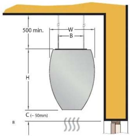
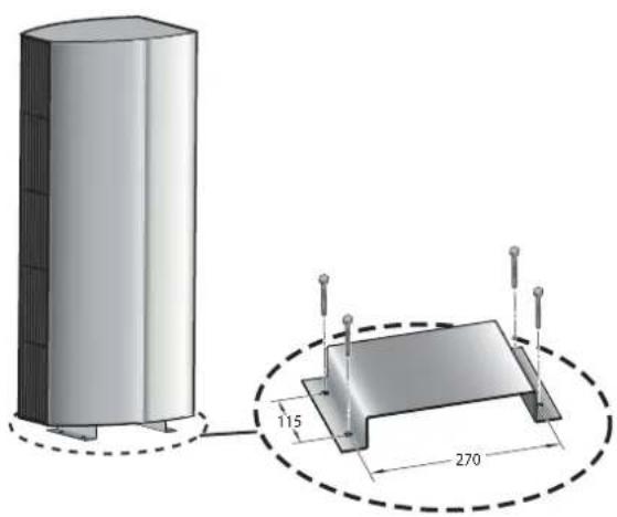
This appliance may be either fixed to a ceiling - see Fig. 1 or floor mounted see Fig. 2 using an appropriate foot.
A minimum distance of 500mm is required from top of the appliance to the ceiling (see Fig. 1) and also the distance between the bottom of the appliance and the top of the door should be kept to a minimum (see 'C' in Fig. 1).
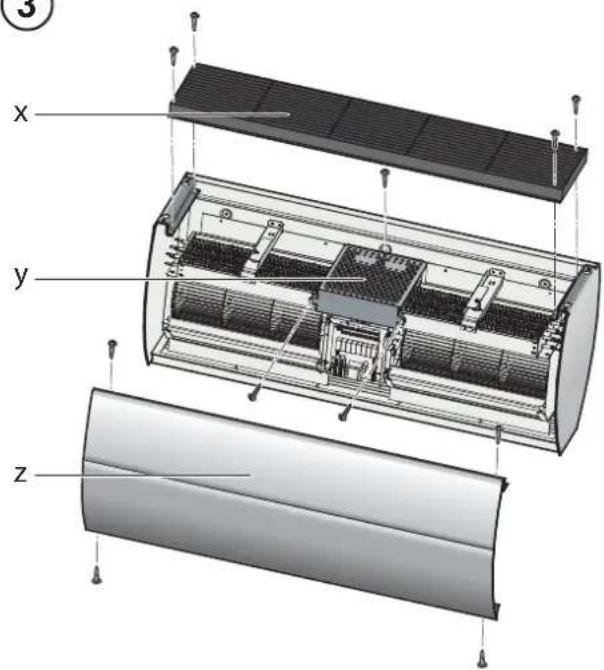
To open the appliance, remove the inlet grilles ('x' in Fig. 3). Remove the front panel ('z' in Fig. 3).
Horizontal Mounting
By using the fixing holes in the top of the air curtain, attachment to a ceiling over the product can be achieved using suitable M10 threaded steel rod or similar supports of sufficient strength - see 's' in Fig. 1.
Vertical Mounting
The architectural range of air curtains can be vertically mounted using a suitable floor foot (Ref: ARCVMF). Contact Dimplex or your service agent for further information. Refer to Fig. 2 for fixing details.
Electrical connection
All products are fitted with a microprocessor control. Electrical power and control connections are made as shown in Fig. 6 & 7. A suitable local isolating switch must be provided in the electrical supply circuit with at least 3mm clearance on each pole. In order to access the electrical connections, remove the inlet grilles (see 'x' in Fig. 3). Remove the front panel (see 'z' in Fig. 3) and also remove the mains cover plate (see 'y' in Fig. 3).
ARC Electric Models
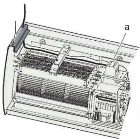
Feed an appropriate supply cable as shown in Fig. 4 and attach to the terminal block (see 'a' in Fig. 4).
Note: Ensure that cables are secured to the cable tray with fixing ties to avoid contact with the elements.
ARC Water/Ambient Models
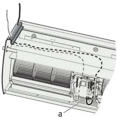
Feed an appropriate supply cable as shown in Fig. 5 and attach to the terminal block (see 'a' in Fig. 5).
A suitable cable for a switch panel (kit ref. - CABC1 for electrically heated models or CABC2 for water heated/ambient models) can be similarly introduced through the top panel and connected to the circuit board.
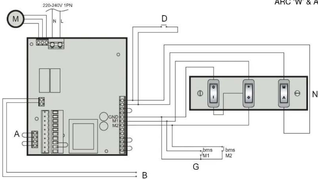
If the unit is to be operated in conjunction with a door switch, a normally closed switch should be wired (see 'D' in Fig. 6 & 7) as appropriate - see also 'Switch Panel Instructions'.
If the unit is to be connected to a Building Energy Management System, connections to be made (see 'G' in Fig. 6 & 7) as appropriate.
Ensure that the air curtain is securely fastened in position and that the supply cables are firmly clamped before operating the appliance.
Water connection
Models designed for use in conjunction with a low pressure hot water supply should be individually connected (in a parallel circuit) to the flow and return pipe-work.
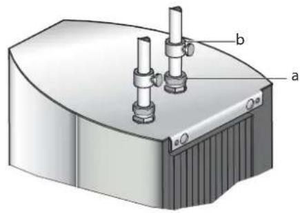
Connections (see 'a' in Fig. 8) are 34 " BSPT and isolation valves (see 'b' in Fig. 8) should be fitted as close to the air curtain connection points as possible. Care should be taken to release as much air as possible to prevent air locks.
Maximum water supply conditions are 100^ C and 10 bar (1.03MPa).
Electrically heated variants
Operation using switch box - CABC1
Switch on electrical supply to the air curtain. Switching the switch marked 'I' energises the fan. The fan switch allows either low or high fan speeds to be selected. The heat selection switch allows heat setting to be chosen.
○ - Off
- 12 heat
- Full heat
The A / M (auto / manual) switch allows for manual over-ride of a door switch if fitted.
The unit should always be switched OFF using the switch box control, and not by mains power supply interruption.
When the unit is switched off (via the switch box) the fan will run on for 1 minute without heat to discharge any residual energy from the heating elements.
When first turned on the control will run through a system check.
The selected settings will be reached and maintained after a 3 minute period.
Door switch control (Electric models)
By including a door switch in the circuit (see 'D' in Fig. 6) the air curtain will respond to door openings as follows:
(1) Door opening will energise the air curtain at the set conditions (switch box settings).
(2) On door closure operation will continue at the set conditions for a further 1 minute.
(3) Between 1 minute and 2 minutes from door closure, set back operation, 12 heat (if heat selected) and 12 fan will activate.
(4) Between 2 minutes and 3 minutes, the fan only ( 12 speed) shut down cycle will be engaged.
(5) After 3 minutes, the air curtain will return to a dormant state until the door is re-opened.
If the door re-opens during this 3 minute run on cycle, the process will restart at (1).
Thermal Safety cut outs
The power supply to the heating elements will be interrupted if one or a combination of the following abnormal events occur:
- Air inlet or outlet grilles are obstructed.
- Internal ventilation is impaired due to build up of dust and fluff.
- Blower unit stalls.
To reset the thermal safety cut-outs, access reset (red) buttons (see Fig. 9). Before re-setting the reason for activation must be determined and corrective action taken.
Low pressure hot water heated / Ambient (fan only) variants
Operation using switch box - CABC2
Switching the switch marked 'I' energises the fan.
The fan switch allows either low or high fan speeds to be selected.
The A / M (auto / manual) switch allows for manual over-ride of a door switch if fitted.
The unit should always be switched OFF using the switch box control, and not by mains power supply interruption.
When first turned on the control will run through a system check.
The selected settings will be reached and maintained after a 3 minute period.
Thermostatic control (optional)
A thermostatic regulation valve with a remote sensing bulb (not supplied) can be positioned in the supply water pipe-work to regulate the heat output.
Door switch control (Water heated & Ambient models)
By including a door switch in the circuit (see 'D' in Fig. 7) the air curtain will respond to door openings as follows:
(1) Door opening will energise the air curtain at the set conditions (switch box settings).
(2) On door closure operation will continue at the set conditions for a further 1 minute.
(3) Between 1 minute and 2 minutes from door closure 12 fan set back operation will activate.
(4) After 2 minutes, the air curtain will return to a dormant state until the door is re-opened. If the door re-opens during this 2 minute run on cycle, the process will re-start at (1).
Wiring Diagrams
ARC 'E' - Electric models - see Fig. 6
ARC 'W' / 'A' - Water heated & Ambient models - see Fig. 7
A - Master Module Link
B - 12VDC Feedback Signal to BMS (Unit Fault Check)
C - Thermostat (Optional)
D - Door Switch (Optional)
E - Thermal Safety Cut-out Circuit
F - Elements
G - BMS Switches (Optional)
M - Motor
N - Switch box
For operation via switch box, all BMS switches as shown in Fig. 6 & 7 need to be OPEN CIRCUIT if used. Do not remove BMS links on PCB.
For operation via BMS, switch box to be set as follows:
I/0 in O (Off) position
Heat selection switch to be in O (Off position)
Fan selection switch in either high or low speed position
| bmsM1 | bmsM2 | bmsH1 | bmsH2 | |
| ▼ | 1 | 0 | ||
| ✕ | X | 1 |
| 1 | 0 | |||
| X | 1 |
O - Circuit Open
1 - Circuit Closed
X - Either Open or Closed
Remote (BMS / BEMS) Operation
Connection to Building Energy Management Control Systems (BEMS) is possible so that remote control of the air-curtain can be carried out in conjunction with other equipment.
Modular Connection
A number of units can be connected together to form one continuous long air curtain. Each appliance should be supplied separately. Simultaneous control of all the air curtains is achieved by linking the PCB's with a modular linking cable found in the modular linking kit. (Kit Ref. - CABM1) Refer to instructions provided with the modular linking kit.
Cleaning
WARNING: DISCONNECT SUPPLY before carrying out maintenance.
External appearance can be maintained by wiping occasionally with a damp cloth; for stain removal, a weak soap solution can be applied with a cloth and the surface wiped dry. Care must be taken to avoid any moisture ingress into the product.
Recycling
For electrical products sold within the European Community.
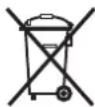
At the end of the electrical products useful life it should not be disposed of with household waste. Please recycle where facilities exist. Check with your Local Authority or retailer for recycling advice in your country.
After Sales Service
Your product is guaranteed for two years from the date of purchase.
Within this period, we undertake to repair or exchange this product free of charge provided it has been installed and operated in accordance with these instructions.
Your rights under this guarantee are additional to your statutory rights, which in turn are not affected by this guarantee.
Should you require after sales service you should contact our customer services help desk on 0845 600 5111. It would assist us if you can quote the model number, series, date of purchase, and nature of the fault at the time of your call. The customer services help desk will also be able to advise you should you need to purchase any spares.
Please do not return a faulty product to us in the first instance as this may result in loss or damage and delay in providing you with a satisfactory service.
Please retain your receipt as proof of purchase.

The product complies with the European Safety Standards EN60335-2-30 and the European Standard Electromagnetic Compatibility (EMC) EN55014, EN60555-2 and EN60555-3 which cover the essential requirements of EEC Directives 73/23 and 89/336
Dimplex UK Limited
Millbrook House
Grange Drive
Hedge End
Southampton
Hampshire. SO30 2DF
UK customer help line 8.00am–5.00pm Mon-Fri and 8:30am-1.00pm Sat (October-March)
Technical Services: Tel. 0845 600 5111
Fax. 01489 773053
e-mail technical.services@dimplex.co.uk
Republic of Ireland Tel. 01 8424833
[c] Dimplex UK Limited
All rights reserved. Material contained in this publication may not be reproduced in whole or in part, without prior permission in writing of Dimplex UK Limited.
- IMPORTANT SAFETY ADVICE
- Electrical
- Fixing Positions
- Horizontal Mounting
- Vertical Mounting
- Electrical connection
- ARC Electric Models
- ARC Water/Ambient Models
- Water connection
- Electrically heated variants
- Operation using switch box - CABC1
- The unit should always be switched OFF using the switch box control, and not by mains power supply interruption.
- Door switch control (Electric models)
- Thermal Safety cut outs
- Low pressure hot water heated / Ambient (fan only) variants
- Operation using switch box - CABC2
- Thermostatic control (optional)
- Door switch control (Water heated & Ambient models)
- Wiring Diagrams
- ARC 'E' - Electric models - see Fig. 6
- ARC 'W' / 'A' - Water heated & Ambient models - see Fig. 7
- Remote (BMS / BEMS) Operation
- Modular Connection
- Cleaning
- Recycling
- After Sales Service
Brand : DIMPLEX
Model : ARC10E
Category : Electric heating