
22003 - Microwaves KENMORE - Free user manual and instructions
Find the device manual for free 22003 KENMORE in PDF.


| Product Type | Built-in Microwave Oven |
| Brand | Kenmore |
| Model | 22003 |
| Color / Finish | Black or Stainless Steel (Trim Kit dependent) |
| Installation Type | Built-in, with optional trim kit |
| Cutout Height | 16 3/4 inches (42.5 cm) |
| Cutout Width | 25 1/2 inches (64.8 cm) |
| Cutout Depth (minimum) | 19 1/2 inches (49.5 cm) with receptacle outside cabinet; 22 inches (55.9 cm) with receptacle inside cabinet |
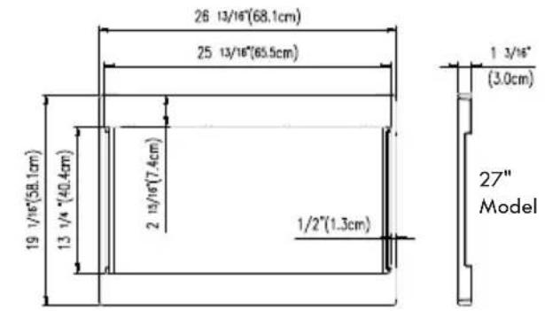
| Trim Frame Width Options | 26 13/16 inches (68.1 cm) or 29 13/16 inches (75.7 cm) |
| Electrical Requirements | 120 V, 60 Hz, AC only, 15-20 A |
| Power Supply Cord | 3-prong grounded plug, 120 V |
| Recommended Circuit | Time-delay fuse or breaker, dedicated circuit |
| Safety Features | Anti-tip bracket, grounding instructions, safety alerts |
| Included Parts | Bottom duct, bottom bracket, anti-tip bracket, top bracket, trim kit frame, screws |
| Warranty | 1 year limited from date of sale, free replacement with proof of purchase |
| Installation Requirements | Grounded outlet within reach; clearance of 1 inch beyond trim frame for airflow |
| Compatible Trim Kits | 111.2200981 (Black), 111.2200381 (Stainless Steel), 111.2270381 (Stainless Steel, narrower) |
| Ventilation | Airflow from top, bottom, and sides of trim frame; do not block |
| Power Rating (estimated) | 1000 W (typical for built-in models) |
| Turntable | Removable, included |
| Manual Language | English, Spanish available via translation request |
Frequently Asked Questions - 22003 KENMORE
User questions about 22003 KENMORE
0 question about this device. Answer the ones you know or ask your own.
Ask a new question about this device
Download the instructions for your Microwaves in PDF format for free! Find your manual 22003 - KENMORE and take your electronic device back in hand. On this page are published all the documents necessary for the use of your device. 22003 by KENMORE.
USER MANUAL 22003 KENMORE
| MICROWAVE OVEN SAFETY | 1 |
| INSTALLATION INSTRUCTIONS | 2 |
| Tools and Parts | 2 |
| Location Requirements | 2 |
| Required Cutout Dimensions | 3 |
| Trim Kit Frame Dimensions | 3 |
| Electrical Requirements | 4 |
| Prepare Microwave Oven | 4 |
| Install the Anti-Tip Bracket | 5 |
| Install Microwave Oven Into Cabinet | 5 |
| Install The Top Bracket | 6 |
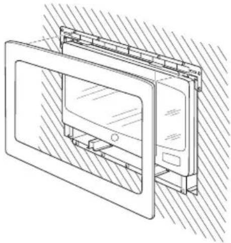
| Install Trim Kit Frame | 6 |
| Replace Any Loose Items | 6 |
Your safety and the safety of others are very important.
We have provided many important safety messages in this manual and on your appliance. Always read and obey all safety messages.

This is the safety alert symbol.
This symbol alerts you to potential hazards that can kill or hurt you and others.
All safety messages will follow the safety alert symbol and either the word "DANGER" or "WARNING."
These words mean:

DANGER

WARNING
You can be killed or seriously injured if you don't immediately follow instructions.
You can be killed or seriously injured if you don't follow instructions.
All safety messages will tell you what the potential hazard is, tell you how to reduce the chance of injury, and tell you what can happen if the instructions are not followed.
Specifications:
TRIM FRAME WIDTH KIT MODEL
29 13/16" (75.7cm) 111.2200981 Black
111.2200381 Stainless Steel
26 13/16" (68.1cm) 111.2270381 Stainless Steel
The Trim Kits can be installed on Kenmore Elite microwave oven models: 111.72213810 and 111.72219810
INSTALLATION INSTRUCTIONS
Location RequirementsTools and Parts
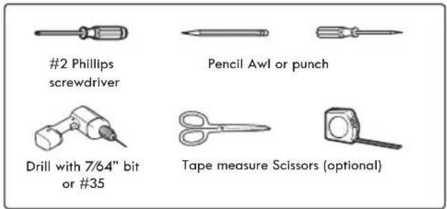
Tools Needed
Gather the required tools and parts before starting installation.
Read and follow the instructions provided with any tools listed here.
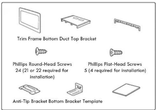
Parts Supplied (not shown to scale)
The microwave oven may be installed over a built-in wall oven. Make sure there is a minimum of 3" (7.6cm) between the top of the lower oven cutout and the microwave oven cutout floor. See Fig. 1 below
The microwave oven may also be installed in a cabinet by itself(without a built-in oven below). For best usability access, there should be a minimum of 36" (91.4) from the floor to the microwave oven cutout floor. Allow a clearance of at least 1-9/16"(4.0cm) below the microwave oven cutout. See Fig.2 below.
In each case, there must be a minimum of 2"(5.1cm) between the cutout opening and a cabinet or surface above. See both figures below.
Fig. 1 Fig. 2

A. Upper cabinet
B. Microwave oven cutout
C. Lower oven cutout
D. Lower cabinets
E. Floor
Required Cutout Dimensions Trim Kit Frame Dimensions
| Models 27" 30" | ||
| Height 16 34 " 16 34 " | ||
| Width 25 12 " 25 12 " | ||
| Depth (min.)* 19 12 " or 22" 19 12 " or 22" |
* Min. depth with receptacle outside cabinet 19½" Min. depth with receptacle inside cabinet 22"


CAUTION
This trim kit uses air flow from the top, bottom and sides of the trim frame. Blocking the air flow can cause the microwave to function improperly and may cause damage to the microwave.
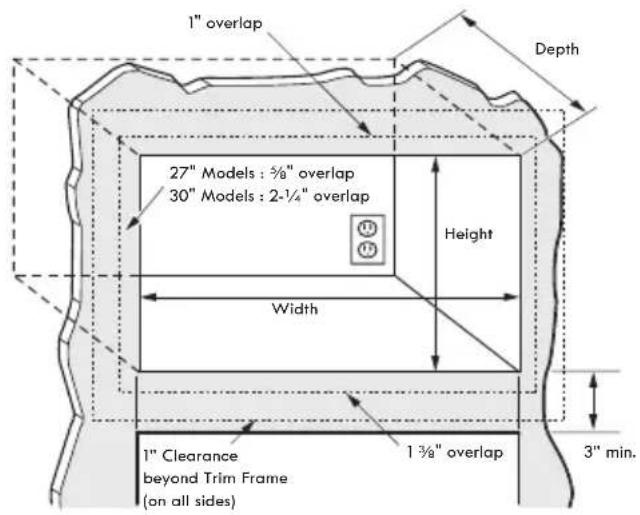
Allow a 1" clearance beyond the edge of the Trim Frame to provide proper air flow.
The Trim Frame will overlap the cutout edges as listed below. Additionally, allow one inch clearance beyond Trim Frame edges on all sides for proper airflow.
26- ^13/_16 " width frame:
1" at top, 1-3/8" at bottom, 5/8" on each side
29-13/16" width frame:
1" at top, 1-3/8" at bottom, 2-1/4" on each side
Electrical Requirements
WARNING
Electrical Shock Hazard
Plug into a grounded 3 prong outlet.
Do not remove ground prong.
Do not use an adapter.
Do not use an extension cord.
Failure to follow these instructions can result in death, fire, or electrical shock.
Install according to all local governing codes and ordinances.
Required:
■ A 120 volt, 60 Hz, AC only, 15- or 20-amp electrical supply with a fuse or circuit breaker.
Recommended:
■ A time-delay fuse or time-delay circuit breaker.
■ A separate circuit serving only this microwave oven.
GROUNDING INSTRUCTIONS
■ For all cord connected appliances:
The microwave oven must be grounded. In the event of an electrical short circuit, grounding reduces the risk of electric shock by providing an escape wire for the electric current. The microwave oven is equipped with a cord having a grounding wire with a grounding plug. The plug must be plugged into an outlet that is properly installed and grounded.
WARNING: Improper use of the grounding plug can result in a risk of electric shock. Consult a qualified electrician or serviceman if the grounding instructions are not completely understood, or if doubt exists as to whether the microwave oven is properly grounded.
Do not use an extension cord. If the power supply cord is too short, have a qualified electrician or serviceman install an outlet near the microwave oven.
SAVE THESE INSTRUCTIONS
Prepare Microwave Oven
Attach Bottom Duct
WARNING: To prevent injury, disconnect power at fuse box or circuit breaker panel to the receptacle into which the microwave oven is plugged.
- Unplug the microwave oven before proceeding with the installation.
- Remove any loose items inside the microwave oven, including the turntable and turntable support.
- Carefully turn the microwave oven upside down.
- Fit the tab on the bottom bracket into the slot on the back of the bottom duct, and push down until the bracket is flush with the bottom of the duct.
Fasten the bottom bracket to the bottom duct by using two round-head screws.
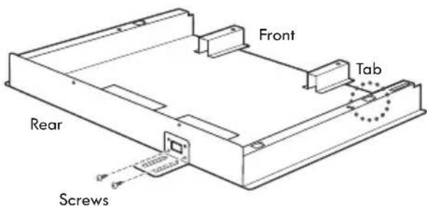
- Line up the tab on the bottom duct with the slot on the bottom of the microwave and insert the tab into the slot.
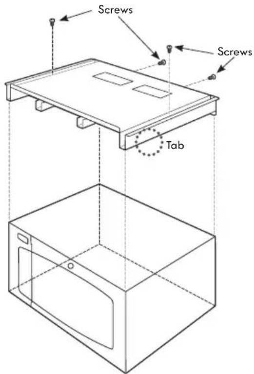
Microwave Oven Upside Down
Install the Anti-Tip Bracket Install Microwave Oven Into Cabinet
- Draw a line on the cutout floor at the center of the cutout, and extend the line V2" down the face of the cabinet.
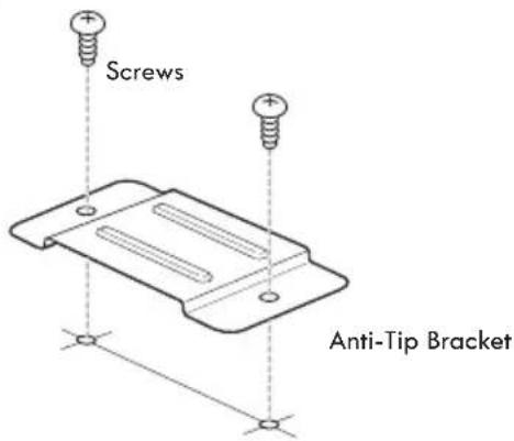
- Fold or cut the front edge of the template, along the front guide line. Place the template flush along the front edge of the cutout floor, aligning the center line of the template with the center line of the cutout floor. Mark the centers of the two screw holes with an awl or center punch for the anti-tip bracket location as shown.
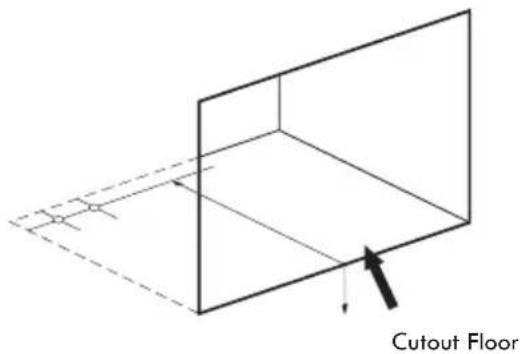
- Remove the template and drill two holes for the anti-tip bracket.
-
Install the anti-tip bracket onto the cutout floor using two round-head screws.
-
Carefully return microwave oven to its upright position.
- Position microwave oven near cutout opening.
WARNING

Electrical Shock Hazard
Plug into a grounded 3 prong outlet.
Do not remove ground prong.
Do not use an adapter.
Do not use an extension cord.
Failure to follow these instructions can result in death, fire, or electrical shock.
-
Plug in microwave oven.
-
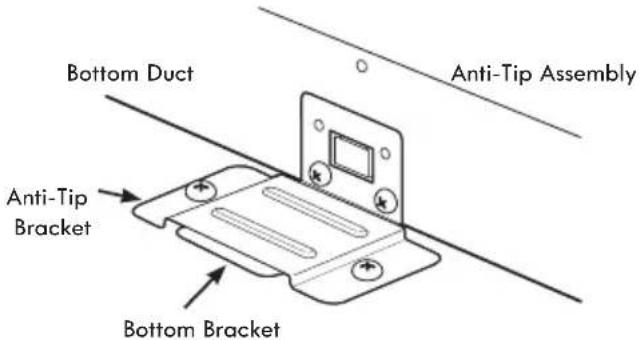
The bottom bracket must be flat to the cutout floor to engage correctly with the anti-tip bracket as shown. Carefully slide the microwave oven back, engaging the anti-tip bracket. Make sure the power cord is not mashed or cut as you slide the microwave into place.
-
Center the microwave oven within the cutout opening.
-
Ensure the microwave oven is accurately centered. Line up the center line on the cabinet with the triangular hole on the front of the bottom duct.
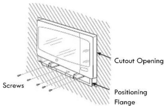
- Drill pilot holes through the positioning flange and then install five round-head screws at the front of the bottom duct as shown.
Install The Top Bracket
- Place the top bracket on the top of the microwave oven, with the tabs on the top and sides of the bracket fitting squarely against the microwave oven.
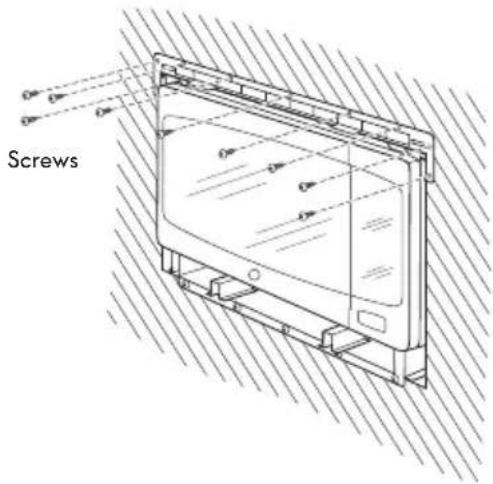
- Drill pilot holes through the holes in the top bracket. Attach the top bracket to the cabinet using nine round-head screws
Install Trim Kit Frame
- Place the trim kit frame over the front surface of the microwave oven.
natural_image
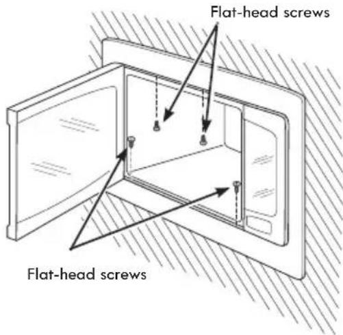
Technical line drawing of a device with a front panel and internal components, no text or symbols present- Open the microwave oven door. Secure the trim kit frame to the top and bottom brackets using four flat-head screws (two on the inside top and two on the inside bottom).
Replace Any Loose Items
-
Your trim kit is now fully installed. Replace any loose items that were removed from the inside of the microwave oven. Save or discard the extra screws. Do not place them in the microwave oven.
-
Keep these installation instructions for future reference.
-
Reconnect power at fuse box or circuit breaker panel to the receptacle into which the microwave oven is plugged.
Table of Contents / Tabla de contenidos
| MICROWAVE OVEN SAFETY | 1 |
| INSTALLATION INSTRUCTIONS | 2 |
| Tools and Parts | 2 |
| Location Requirements | 2 |
| Required Cutout Dimensions | 3 |
| Trim Kit Frame Dimensions | 3 |
| Electrical Requirements | 4 |
| Prepare Microwave Oven | 4 |
| Install the Anti-Tip Bracket | 5 |
| Install Microwave Oven Into Cabinet | 5 |
| Install The Top Bracket | 6 |
| Install Trim Kit Frame | 6 |
| Replace Any Loose Items | 6 |
natural_image
Pure 3D wireframe diagram of a rectangular prism with dashed hidden lines and an arrow indicating direction (no text or symbols)Piso del Recorte
natural_image
Technical line drawing of a door frame with hatched shading, showing internal components and mounting brackets (no text or symbols)FOR ONE YEAR from the date of sale this product is warranted against defects in material or workmanship when it is correctly installed according to all supplied instructions.
WITH PROOF OF SALE, return a defective product to the retailer from which it was purchased for free replacement.
This warranty is void if this appliance is ever used for other than private household purposes.
This warranty gives you specific legal rights, and you may also have other rights which vary from state to state.
Sears Brands Management Corporation, Hoffman Estates, IL 60179
GARANTÍA LIMITADA DE KENMORE
Sears Brands Management Corporation, Hoffman Estates, IL 60179
ABOUT THIS MANUAL
(주) 신광씨링
광주광역시 서구 하남대로
502번길 14
- Your safety and the safety of others are very important.
- DANGER
- WARNING
- Specifications:
- INSTALLATION INSTRUCTIONS
- Location RequirementsTools and Parts
- Tools Needed
- Required Cutout Dimensions Trim Kit Frame Dimensions
- CAUTION
- Electrical Requirements
- Required:
- Recommended:
- GROUNDING INSTRUCTIONS
- ■ For all cord connected appliances:
- SAVE THESE INSTRUCTIONS
- Prepare Microwave Oven
- Attach Bottom Duct
- Install the Anti-Tip Bracket Install Microwave Oven Into Cabinet
- Electrical Shock Hazard
- Install The Top Bracket
- Install Trim Kit Frame
- Replace Any Loose Items
- GARANTÍA LIMITADA DE KENMORE
- ABOUT THIS MANUAL
Brand : KENMORE
Model : 22003
Category : Microwaves