
PMV38 - Motorized valve Salus - Free user manual and instructions
Find the device manual for free PMV38 Salus in PDF.


| Product Type | Programmable Thermostat |
| Brand | Salus |
| Model | PMV38 |
| Dimensions (H x W x D) | 120 x 80 x 25 mm |
| Weight | 150 g |
| Power Supply | 2 x AA batteries (not included) |
| Display | LCD with backlight |
| Temperature Range | 5°C to 35°C |
| Accuracy | ±1°C |
| Programmable | Yes, 7-day schedule |
| Control Method | Manual / Programmable modes |
| Wireless Connectivity | None (standalone) |
| Wall Mounting | Yes |
| Certifications | CE |
| Operating Humidity | 10% to 90% non-condensing |
| Storage Temperature | -10°C to 50°C |
| Included Accessories | Screws, wall plugs, user manual |
| Maintenance | Clean with a soft, dry cloth. Do not use water or cleaning agents. |
| Safety | Low voltage device; avoid water exposure. |
| Spare Parts | Batteries, mounting plate (available from Salus) |
| General Information | This thermostat is designed for residential heating control. |
Frequently Asked Questions - PMV38 Salus
User questions about PMV38 Salus
0 question about this device. Answer the ones you know or ask your own.
Ask a new question about this device
Download the instructions for your Motorized valve in PDF format for free! Find your manual PMV38 - Salus and take your electronic device back in hand. On this page are published all the documents necessary for the use of your device. PMV38 by Salus.
USER MANUAL PMV38 Salus
3 PORT MOTORISED VALVE
PMV31 (1") PMV32 (22 mm) PMV34 (3/4") PMV38 (28 mm)
PRODUCT COMPLIANCE
This product complies with the essential requirements of the following EC Directives:
• Electro-Magnetic Compatibility Directive 2014/30/EU
• Low Voltage Directive 2014/35/EU
• RoHS 2011/65/EU
SAFETY INFORMATION
These instructions are applicable to the SALUS Controls model stated on the front cover of this manual only, and must not be used with any other make or model.
This accessory must be fitted by a Competent person, and installation must comply with the guidance provided in the current sections of BS7671 (ICE Wiring Regulations) and Part 1 ^a of the Building Regulations. Failure to comply with the requirements of these publications could lead to prosecution.
Always isolate the AC Main supply before removing or refitting the actuator assembly.
Please leave these instructions with the end user where they should be kept in a safe place for future reference.
INTRODUCTION
A motorised valve is used to control the flow of water in a central heating system. The motorised valve can be used for control of both heating and hot water, and it works by controlling the flow of water from the heating boiler to other parts of the system.
There are two types of motorised valve used in domestic heating systems: two port (also called zone valves), and three port (also called mid-position valves). SALUS Controls offers both types of valve in a range of standard port sizes.
FEATURES
- Three port option in 1", 22mm, 3/4" and 28mm sizes
• Removable actuator assembly
• Manual lever and position indicator
- Some return
- Industry standard wiring
INSTALLATION
Please read the important safety information at the start of this manual before you begin to install the device.
Before Installation
This valve must only be installed in compatible systems. Before installing, please check that:
• The system pipework has been flushed out to remove any residue.
- There is enough clearance around the valve to allow removal and refitting of the actuator.
- The valve is not installed with the actuator facing down.
• The supply voltage is the same as the voltage indicated on the actuator covers.
- The main water pressure and the pressure differentials between valve ports are suitable for this valve (see Product Specification).
Do not restore the mains supply to the system until all associated items are fully installed.
NOTE. All electrical installation work should be carried out by a suitably qualified electrician or other competent person. If you are not sure how to install this motorised valve consult either with a qualified electrician, heating engineer or your boiler / heating system supplier for advice on how to continue.
Electrical Connection
The electric connections to the motorised valve are made using the pre-wired cable. This simplifies installation, as no connections need to be made to the actuator itself. The connecting cable uses industry standard colours, and the connection details are shown below:
When A is open & B is closed; water flows out from A;
When B is open & A, s closed; water flows out from B;
Control wire (Power Supply AC 230V) White - Live. Blue - Neutral
When A is open & B is closed; white 0½, Blue is N:
When B is open & A is closed; white 230V, Blue is N;
Auxiliary switch output (CON, NO) Orange = CON. Grey = NO
Yellow/ Green wire = Earth
When valve is open, orange and grey AUX switch is closed. When valve is closed, orange and grey AUX switch is open. Yellow/Creen wire is for earth.


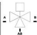
Note: For basic diverter valve applications please isolate / Disregard the orange wire. But connect white and grey together.
MANUAL LEVER
There is a ever on the side of the actuator cover: this lever allows manual operation of the valve, e.g. for refilling and draining of the system or if the actuator lasts. For two way valves, the lever allows the valve to be kept open; with three way valves the lever allows both ports A and B to be open at the same time.
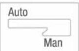
To manually operate the valve, gently push the lever forward and latch it in the MAN position. The valve will automatically return to AUTO when the actuator is powered up again.
NOTE: Push the manual ever slowly to prevent damage to the actuator motor and gear system. The valve should be in manual position to be fitted.
ACTUATOR REMOVAL AND REFITTING
The valve actuator can be removed or refitted without having to disturb the valve installation.
Removal:
-
Remove actuator cover
-
Lock lever in "MAN" position
3 Loosen Z securing screws
- Lift actuator from valve body
Re-fitting:
-
Remove actuator cover
-
Lock lever in "MAN" position
-
Turn valve stem to parallel position
as indicated
-
Push actuator onto valve
-
Tighten 2 securing screws
-
Release ever and allow to travel back to 'AUTO'
Note: Do not attempt to dismantle the actuator assembly as it contains no user serviceable parts.
- dismantling or tampering with the actuator assembly will invalidate the product warranty.
MAINTENANCE
The Motorised Valve requires no special maintenance. Periodically, the outer casing can be wiped clean using a dry cloth (please DO VOT use sovents, polishes, detergents or abrasive cleaners, as these can damage the Motorised Valve).
There are no user serviceable parts within the unit, any servicing or repairs should only be carried out by SAI US Controls or their appointed agents.
Should the Motorised Valve fail to function correctly, check
• The heating system is switched on
• The ever s not latched in the MANUAL position.
PRODUCT SPECIFICATION
Model: 3 port motorized valve PMV31/32/34/38
Type: Motorised valve designed for domestic heating applications.
Electrical
Switching Voltage: 230V AC/50Hz
Power Consumption: SW
Response
Opening: 14 seconds
Closing: 3 seconds
Differential Pressure
Pipe size 3 Way
22mm 0.8 bar
28mm 0.5 bar
Max Static Pressure: 8.6 bar
Operating Temperatures
Min Fluid Temperature: 5 °C
Max Fluid Temperature: 88 °C
Environment
Operating Temperature: -10°C to +80°C
Storage Temperature: -20°C to +65°C
Protection class: IP20
SALUS CONTROL S.P.C. SALUS HOUSE, DOOWDARIE BUSINESS PARK SOUTH
WHINRY ROAD, COOKAGE H. BARKS - EY SP 259
SALES 1-44 (3) 1226-32396 + E sales@maus tech.com
TECHNICAL 1-44 (3) 1226-32396 • Etechstatus-tech.com
www.salus.com controls.com
Brand : Salus
Model : PMV38
Category : Motorized valve