
DS-TPS100 - Detector Hikvision - Free user manual and instructions
Find the device manual for free DS-TPS100 Hikvision in PDF.


| Product Type | Vehicle Detection Sensor |
| Model | DS-TPS100 |
| Brand | Hikvision |
| Dimensions (W x H x D) | 120 mm x 100 mm x 50 mm |
| Weight | 0.5 kg |
| Power Supply | 12 V DC, 24 V AC |
| Power Consumption | < 10 W |
| Detection Technology | Inductive loop, radar or camera-based (varies by variant) |
| Detection Range | Up to 20 meters |
| Operating Temperature | -30°C to +70°C |
| Ingress Protection | IP65 |
| Main Functions | Vehicle presence detection, direction sensing, speed measurement, count |
| Output | Relay, RS-485, optional Ethernet |
| Installation Type | Surface mount, flush mount, or pole mount |
| Maintenance | Clean lens (if camera) with soft cloth; check connections periodically |
| Safety | Overcurrent protection, reverse polarity protection |
| Spare Parts & Repairability | Replacement mounting bracket, cable, lens kit; contact Hikvision support |
| General Information | Supports multiple detection zones, configurable via software |
Frequently Asked Questions - DS-TPS100 Hikvision
User questions about DS-TPS100 Hikvision
0 question about this device. Answer the ones you know or ask your own.
Ask a new question about this device
Download the instructions for your Detector in PDF format for free! Find your manual DS-TPS100 - Hikvision and take your electronic device back in hand. On this page are published all the documents necessary for the use of your device. DS-TPS100 by Hikvision.
USER MANUAL DS-TPS100 Hikvision
natural_image
Abstract geometric design with red diamond shapes, gray squares, and a white globe symbol on a red background (no text or symbols)Parking Lot Vehicle Detection Server
User Manual
User Manual
COPYRIGHT © 2018 Hangzhou Hikvision Digital Technology Co., Ltd.
ALL RIGHTS RESERVED.
Any and all informaon, including, among others, wordings, pictures, graphs are the properes of Hangzhou Hikvision Digital Technology Co., Ltd. or its subsidiaries (hereinaer referred to be "Hikvision"). This user manual (hereinaer referred to be "the Manual") cannot be reproduced, changed, translated, or distributed, parally or wholly, by any means, without the prior written permission of Hikvision. Unless otherwise spulated, Hikvision does not make any warranties, guarantees or representaons, express or implied, regarding to the Manual.
About this Manual
This Manual is applicable to Parking Lot Vehicle Detecon Server.
The Manual includes instrucons for using and managing the product. Pictures, charts, images and all other informaon hereinaer are for descripon and explanaon only. The informaon contained in the Manual is subject to change, without noce, due to rmware updates or other reasons. Please nd the latest version in the company website
(hp://overseas.hikvision.com/en/).
Please use this user manual under the guidance of professionals.
Trademarks Acknowledgement
HIKVISION and other Hikvision's trademarks and logos are the properes of Hikvision in various jurisdicons. Other trademarks and logos menoned below are the properes of their respective owners.
Legal Disclaimer
TO THE MAXIMUM EXTENT PERMITTED BY APPLICABLE LAW, THE PRODUCT DESCRIBED, WITH ITS HARDWARE, SOFTWARE AND FIRMWARE, IS PROVIDED "AS IS", WITH ALL FAULTS AND ERRORS, AND HIKVISION MAKES NO WARRANTIES, EXPRESS OR IMPLIED, INCLUDING WITHOUT LIMITATION, MERCHANTABILITY, SATISFACTORY QUALITY, FITNESS FOR A PARTICULAR PURPOSE, AND NON-INFRINGEMENT OF THIRD PARTY. IN NO EVENT WILL HIKVISION, ITS DIRECTORS, OFFICERS, EMPLOYEES, OR AGENTS BE LIABLE TO YOU FOR ANY SPECIAL, CONSEQUENTIAL, INCIDENTAL, OR INDIRECT DAMAGES, INCLUDING, AMONG OTHERS, DAMAGES FOR LOSS OF BUSINESS PROFITS, BUSINESS INTERRUPTION, OR LOSS OF DATA OR DOCUMENTATION, IN CONNECTION WITH THE USE OF THIS PRODUCT, EVEN IF HIKVISION HAS BEEN ADVISED OF THE POSSIBILITY OF SUCH DAMAGES.
REGARDING TO THE PRODUCT WITH INTERNET ACCESS, THE USE OF PRODUCT SHALL BE WHOLLY AT YOUR OWN RISKS. HIKVISION SHALL NOT TAKE ANY RESPONSIBILITES FOR ABNORMAL OPERATION, PRIVACY LEAKAGE OR OTHER DAMAGES RESULTING FROM CYBER ATTACK, HACKER ATTACK, VIRUS INSPECTION, OR OTHER INTERNET SECURITY RISKS; HOWEVER, HIKVISION WILL PROVIDE TIMELY TECHNICAL SUPPORT IF REQUIRED.
SURVEILLANCE LAWS VARY BY JURISDICTION. PLEASE CHECK ALL RELEVANT LAWS IN YOUR JURISDICTION BEFORE USING THIS PRODUCT IN ORDER TO ENSURE THAT YOUR USE CONFORMS THE APPLICABLE LAW. HIKVISION SHALL NOT BE LIABLE IN THE EVENT THAT THIS PRODUCT IS USED WITH ILLEGITIMATE PURPOSES.
IN THE EVENT OF ANY CONFLICTS BETWEEN THIS MANUAL AND THE APPLICABLE LAW, THE LATER PREVAILS.
Symbol Conventions
The symbols that may be found in this document are dened as follows.
| Symbol | Description |
 NOTE NOTE | Provides additional informaon to emphasize or supplement important points of the main text. |
 WARNING WARNING | Indicates a potentially hazardous situaon, which if not avoided, could result in equipment damage, data loss, performance degradaon, or unexpected results. |
 DANGER DANGER | Indicates a hazard with a high level of risk, which if not avoided, will result in death or serious injury. |
Safety Instructions
- Proper conguraon of all passwords and other security sengs is the responsibility of the installer and/or end-user.
- In the use of the product, you must be in strict compliance with the electrical safety regulaons of the naon and region. Please refer to technical specicaons for detailed informaon.
- Enter voltage should meet both the SELV (Safety Extra Low Voltage) and the Limited Power Source with 100 to 240 VAC or 12 VDC according to the IEC60950-1 standard. Please refer to technical speciaons for detailed informaon.
- Do not connect several devices to one power adapter as adapter overload may cause over-heang or a re hazard.
- Please make sure that the plug is rmly connected to the power socket.
- If smoke, odor or noise rise from the device, turn o the power at once and unplug the power cable, and then please contact the service center.
Preventive and Cautionary Tips
Before connecng and operang your device, please be advised of the following ps:
- Ensure environmental conditions meet factory speciaons.
- Ensure unit is properly secured to a rack or shelf. Major shocks or jolts to the unit as a result of dropping it may cause damage to the sensitive electronics within the unit.
- Use the device in conjuncon with an UPS if possible.
● Power down the unit before connecng and disconnectg accessories and peripherals.
● A factory recommended HDD should be used for this device. - Improper use or replacement of the battery may result in hazard of explosion. Replace with the same or equivalent type only. Dispose of used baeries according to the instrucons provided by the baery manufacturer.
Table of Contents
Chapter 1 Key Features....5
Chapter 2 Introducon....6
2.1 Panel Introducon 6
2.2 Typical Applicaon....7
Chapter 3 Geng Started....8
3.1 Starng Up and Shung Down 8
3.1.1 Starng Up....8
3.1.2 Shung Down 8
3.2 Setting the Admin Password 8
Chapter 4 Network Seings....10
4.1 External Network Setngs 10
4.2 Internal Network Sengs 11
4.3 Remote Access Configuraon 11
4.4 Static Router....12
Chapter 5 TPM Management....14
Chapter 6 Device Parameters ...... 15
6.1 Device Informaon 15
6.2 Time Settings....15
6.3 DST Setngs.... 16
Chapter 7 Other Setngs .... 18
7.1 User Management....18
7.1.1 Adding a User....18
7.1.2 Modifying a User....19
7.1.3 Deleng a User 19
7.2 Maintenance 20
7.2.1 Reboong the Device 20
7.2.2 Default Sengs.... 20
7.2.3 Exporng/Imporng Conguration File.... 21
7.2.4 Remote Upgrade 21
Chapter 1 Key Features
- Dual GPU architecture with deep-learning algorithm. Strong environment adaptability.
● Parking space status detecon and license plate recognition. - Provides high algorithm eciency for picture analysis.
- Upgrades the old solution with new device, reducing the labor cost and project cycle.
● Easy to upgrade and maintain. Low management cost.
Chapter 2 Introduction
Purpose:
DS-TPS100 Parking Lot Vehicle Detecon Server is based on deep-learning algorithm that has the ability of parking space detecon and license plate recognition. By analyzing vehicle features, it improves the accuracy and stability of parking space detecon and license plate recognition.
2.1 Panel Introduction
The front panel view is shown below:
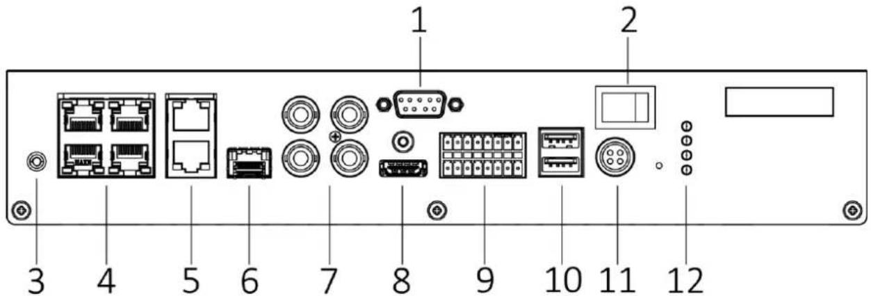
Figure 2-1 Front Panel View
Table 2-1 Descripon of Front Panel
| No. | Name | No. | Name |
| 1 | RS-232 serial interface | 9 | RS-485 serial interface |
| 2 | Power switch | RS-232 serial interface | |
| 3 | GND | Alarm input | |
| 4 | 10/100M self-adapve Ethernet interfaces | Alarm output | |
| 5 | 100/1000M self-adapve G2/G1 Ethernet interface | 10 | USB 2.0 interfaces |
| 6 | Opcal interface | 11 | 12 VDC power input |
| 7 | Video inputs | 12 | Status indicators |
| 8 | HDMI interface |
2.2 Typical Application
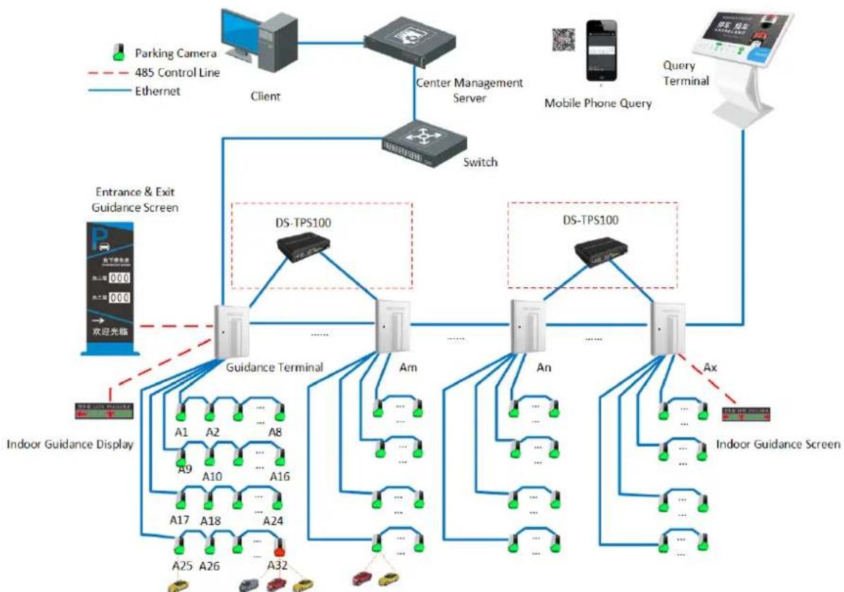
flowchart
graph TD
    A["Client"] --> B["Center Management Server"]
    B --> C["Switch"]
    C --> D["Advance & Exit Guidance Screen"]
    D --> E["Guidance Terminal"]
    D --> F["An"]
    D --> G["An"]
    D --> H["Ax"]
    E --> I["Indoor Guidance Display"]
    F --> J["Indoor Guidance Screen"]
    G --> K["Indoor Guidance Screen"]
    L["Parking Camera 485 Control Line Ethernet"] -.-> E
    M["Mobile Phone Query"] --> N["Query Terminal"]
Figure 2-2 Typical Applicaon
Chapter 3 Getting Started
3.1 Starting Up and Shutting Down
Purpose:
Proper startup and shutdown procedures are crucial to expanding the life of the device.
3.1.1 Starting Up
Before you start:
- Fix the device in an equipment cabinet.
- Ensure the device is properly grounded.
- Plug the network cable
Plug the power supply to start up.

Make sure the power supply is plugged into an electrical outlet. It is HIGHLY recommended that an Uninterruptible Power Supply (UPS) be used in conjunction with the device.
3.1.2 Shutting Down
Unplug the power supply to shut down.
3.2 Setting the Admin Password
Purpose:
For the rst-me access, you need to acvate the device by seng an admin password. No operaon is allowed before acvaon. You can also acvate the device via Web Browser, SADP or Client Soware.
Before you start:
Set the IP address of your computer. Make sure the device is in the same network segment with your computer.

● The default IP address for G1 network interface is 192.1.0.64.
● The default IP address for G2 network interface is 192.168.1.64.
Step 1 Enter device IP address in address bar of the browser and press Enter. Thus the acvaon interface pops up.
Step 2 Enter the Admin Password and Conrm Password.
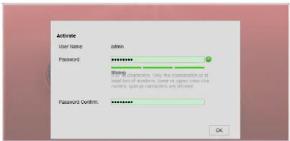
Figure 3-1 Seng Admin Password

WARNING
STRONG PASSWORD RECOMMENDED— We highly recommend you create a strong password of your own choosing (using a minimum of 8 characters, including upper case leers, lower case leers, numbers, and special characters) in order to increase the security of your product. And we recommend you reset your password regularly, especially in the high security system, reseng the password monthly or weekly can beer protect your product.
Step 3 Click OK to set the admin password.
Step 4 Aer successful login, follow the prompt to install the plug-in.
Chapter 4 Network Settings
Purpose:
Guarantee the network conncon between your computer and the device is correct, thus you can control the device remotely.
4.1 External Network Settings
Step 1 Enter External Network Sengs interface.
Conguraon > Remote Conguraon > Network Sengs > External Network Sengs
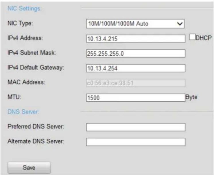
Figure 4-1 Basic Network Sengs
Step 2 Set the NIC Sengs.
1) Select the NIC Type in the dropdown list.
2) Enter IPv4 Address, IPv4 Subnet Mask, IPv4 Default Gateway. Or you can select DHCP (Dynamic Host Conguraon Protocol) to obtain IPv4 address dynamically.
Step 3 Set the DNS Server.
Enter the Preferred DNS Server and Alternate DNS Server.
Step 4 Click Save to save the above sengs.
4.2 Internal Network Settings
Purpose:
You can congregate the IP address for the network interfaces. The default IP address is 192.1.0.64.
Step 1 Enter Internal Network Sengs interface.
Conguraon > Remote Conguraon > Network Sengs > Internal Network Sengs
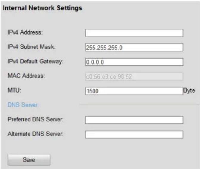
Figure 4-2 Basic Network Sengs
Step 2 Set the NIC Sengs.
1) Select the NIC Type in the dropdown list.
2) Enter IPv4 Address, IPv4 Subnet Mask, IPv4 Default Gateway. Or you can select DHCP (Dynamic Host Conguraon Protocol) to obtain IPv4 address dynamically.
Step 3 Set the DNS Server.
Enter the Preferred DNS Server and Alternate DNS Server.
Step 4 Click Save to save the above sengs.
4.3 Remote Access Configuration
Purpose:
SSH (Secure Shell) as a security protocol ensures network security for the remote accessing and other network service. It prevents informaon leakage issues during remote management.
Step 1 Enter Remote Access Conguraon interface
Conguraon > Remote Conguraon > Network Sengs > Remote Access Conguraon
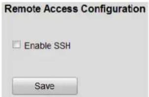
Figure 4-3 Remote Access Conguraon
Step 2 Check the checkbox of SSH.
Step 3 Click Save to enable it.
4.4 Static Router
Purpose:
To access dierent local networks via G1 and G2 network interface, you need to conjure stac router. If you do not specify a router, the device will visit network via the default G1 gateway.
Step 1 Enter Stac Router interface
Conguraon > Remote Conguraon > Network Sengs > Stac Router
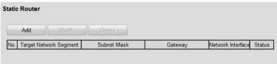
Figure 4-4 Stac Router
Step 2 Click the Add buon.
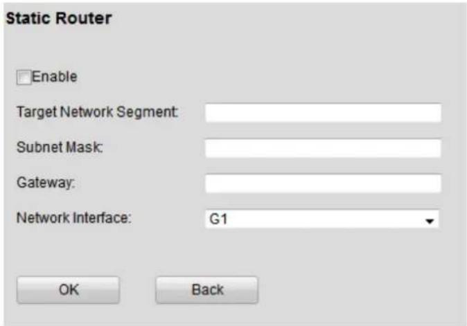
Figure 4-5 Add
Step 3 Check Enable.
Step 4 Enter Target Network Segment, Subnet Mask, and Gateway.
● Target Network Segment: The network segment of target server.
- Subnet Mask: subnet mask of target network segment.
● Gateway: gateway for the selected network interface.
Step 5 Select Network Interface.
Step 6 Click OK.
Chapter 5 TPM Management
Purpose:
TPM (Trac Processor Manager) can help you to nd the vehicle and free parking space quickly. By adding TPM, server can analyze parking space status and plate license.
Step 1 Go to Conguraon > Remote Conguraon > TPM Management.
Step 2 Click Add.
Step 3 Enter TPM informaon.
Step 4 Click OK.

Up to 4 TPMs can be added. Before add other TPMs, congure dierent device number for dierent TPM.
Chapter 6 Device Parameters
6.1 Device Information
Purpose:
You can enter Device Informaon interface to view the basic informaon of device.
Step 1 Enter Device Informaon interface.
Conguraon > Remote Conguraon > Device Parameters > Device Informaon
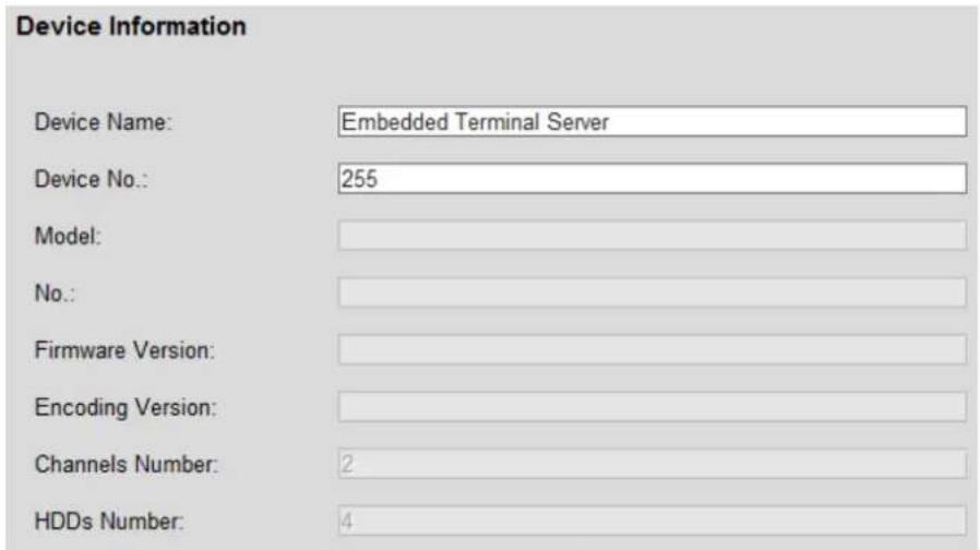
Figure 6-1 Device Informaon
6.2 Time Settings
Purpose:
You can synchronize the date and me of the device manually or automacally.
Step 1 Enter Time Sengs interface.
Conguraon > Remote Conguraon > Device Parameters > Time Sengs
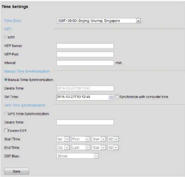
Figure 6-2 Time Sengs
Step 2 Select Time Zone from the dropdown list.
Step 3 Select the clock synchronizaon mode as NTP, Manual Time Synchronizaon or GPS Time Synchronizaon.
NTP
Enter NTP Server, NTP Port and Interval me.
● Manual Time Synchronizaon
Enter the me and date in Set Time. Or you can select Synchronize with computer me.
6.3 DST Settings
Purpose:
DST (Daylight Saving Time) is the pracce of advancing clocks during summer months by specied hours so that evening daylight lasts specied hours longer while sacrificing normal sunrise mes.
Step 1 Enter the General Sengs interface.
Conguraon > Remote Conguraon > Device Parameters > Time Sengs
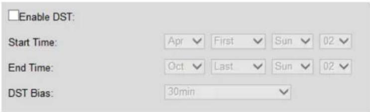
Figure 6-3 DST Sengs Interface
Step 2 Check the checkbox of Enable DST.
Step 3 Set Start Time, End Time, and DST Bias.
Step 4 Or you can manually check the Enable DST checkbox, and then you choose the date of the DST period.
Chapter 7 Other Settings
7.1 User Management
Purpose:
You can add, edit, and delete users.
Step 1 Enter User Management interface.
Conguraon > Remote Conguraon > User Management
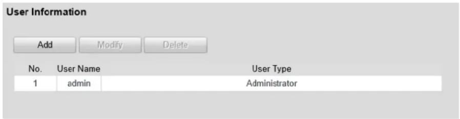
Figure 7-1 User Management
7.1.1 Adding a User
Step 1 Click Add to enter the Add user interface.
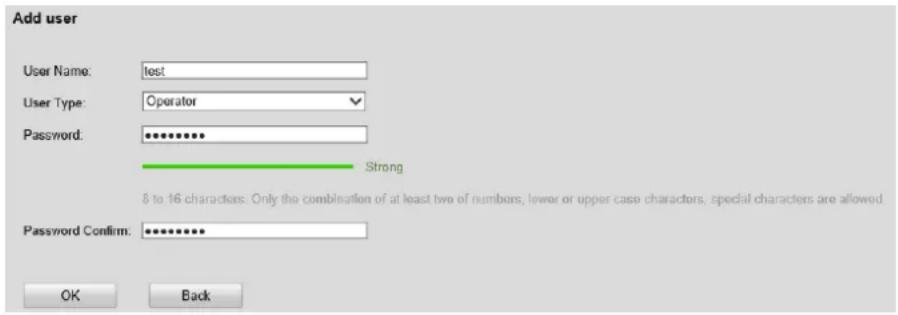
Figure 7-2 Add User
Step 2 Enter User Name.
Step 3 Enter the same password in Password and Password Conrm.

WARNING
STRONG PASSWORD RECOMMENDED— We highly recommend you create a strong password of your own choosing (using a minimum of 8 characters, including upper case leers, lower case leers, numbers, and special characters) in order to increase the security of your product. And we recommend you reset your password regularly, especially in the high security system, reseng the password monthly or weekly can beer protect your product.
Step 4 Select User Type as Operator or User.
- Operator: The Operator user level has permission of Local Log Search in Local Conguraon, Remote Log Search and Two-way Audio in Remote Conguraon and all operang permission in Camera Conguraon.
- User: The Guest user has permission of Local Log Search in Local Conguraon, Remote Log Search in Remote Conguraon and only has the local/remote playback in the Camera Conguraon.
Step 5 Click OK to add the user.
7.1.2 Modifying a User

You need the admin password to modify the admin user.
Step 1 Select a user account from the list on the User Informaon interface to be modified.
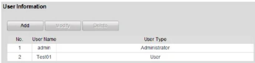
Figure 7-3 Select a User
Step 2 Click Modify.
Step 3 Modify user informaon.

WARNING
STRONG PASSWORD RECOMMENDED— We highly recommend you create a strong password of your own choosing (using a minimum of 8 characters, including upper case leers, lower case leers, numbers, and special characters) in order to increase the security of your product. And we recommend you reset your password regularly, especially in the high security system, reseng the password monthly or weekly can beer protect your product.
Step 4 Click OK to nish the user modicaon.
7.1.3 Deleting a User
Step 1 Select a user account from the list on the User Informaon interface to be deleted.
Step 2 Click Delete, and the informaon box will pop up.
Step 3 Click OK to delete the selected user account.
7.2 Maintenance
Purpose:
You can restart, restore default, repair database index, export/import conguraon le, and upgrade device.
Step 1 Enter Maintenance interface.
Conguraon > Remote Conguraon > Maintenance
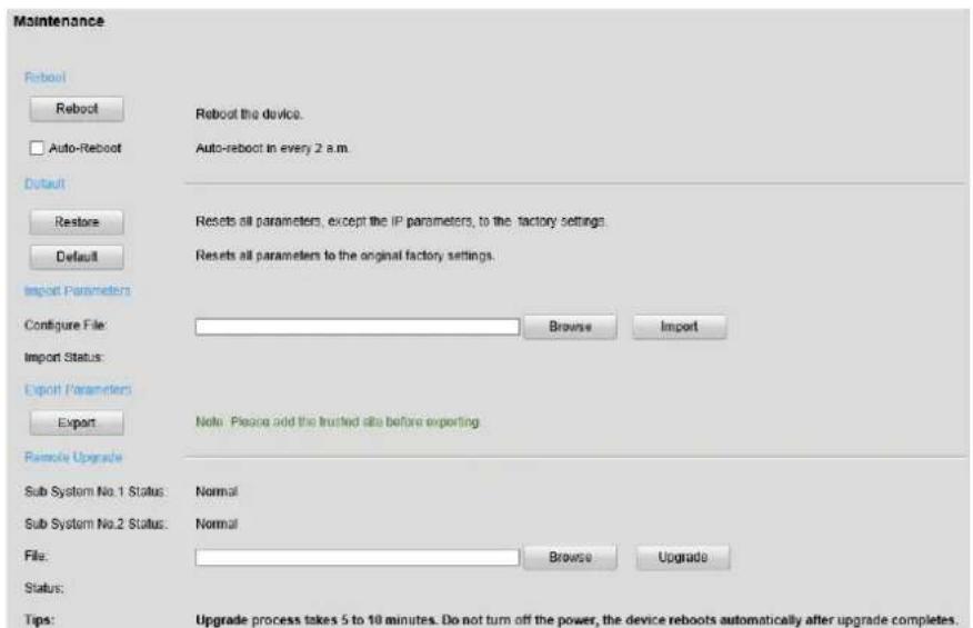
Figure 7-4 Maintenance
7.2.1 Rebooting the Device
- Click Reboot to reboot the device.
- Check Auto-Reboot checkbox. Then the device reboots automacally 2 a.m. every day.
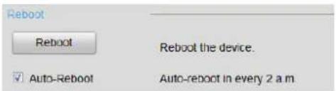
Figure 7-5 Restart
7.2.2 Default Settings
Step 1 Select the restoring type as Restore or Default.
- Restore: Restore all parameters, except the network (including IP address, subnet mask, gateway, MTU, NIC working mode, default route, server port, etc.) and user account parameters, to the factory default sengs.
- Default: Restore all parameters to the factory default settings.

Figure 7-6 Default
7.2.3 Exporting/Importing Configuration File
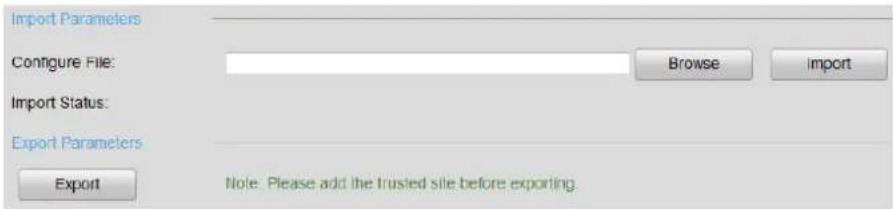
Figure 7-7 Imporng/Exporng Conguraon File
- Import conguraon le.
1) Click Browser.
2) Select conguraon le path.
3) Click Import to import the selected le.
- Export conguraon le.
1) Click Export.
2) Select exporng path.
3) Click Save to save the conguraon le.
7.2.4 Remote Upgrade
Step 1 Click Browse.
Step 2 Select upgrade le.
Step 3 Click Upgrade to upgrade.
Sub System No. 1/2 Status: The status of analysis modules. You can only upgrade device when the status is normal.
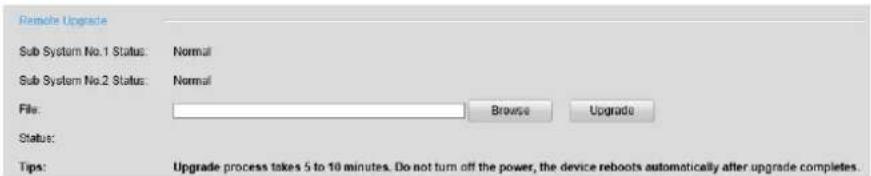
Figure 7-8 Remote Upgrade

See Far, Go Further
- User Manual
- ALL RIGHTS RESERVED.
- About this Manual
- Trademarks Acknowledgement
- Legal Disclaimer
- Symbol Conventions
- Safety Instructions
- Preventive and Cautionary Tips
- Table of Contents
- Chapter 1 Key Features....5
- Chapter 2 Introducon....6
- Chapter 3 Geng Started....8
- Chapter 4 Network Seings....10
- Chapter 5 TPM Management....14
- Chapter 6 Device Parameters ...... 15
- Chapter 7 Other Setngs .... 18
- Chapter 1 Key Features
- Chapter 2 Introduction
- Purpose:
- Panel Introduction
- Typical Application
- Chapter 3 Getting Started
- Starting Up and Shutting Down
- Starting Up
- Before you start:
- Shutting Down
- Setting the Admin Password
- WARNING
- Chapter 4 Network Settings
- External Network Settings
- Internal Network Settings
- Remote Access Configuration
- Static Router
- Chapter 5 TPM Management
- Chapter 6 Device Parameters
- Device Information
- Time Settings
- DST Settings
- Chapter 7 Other Settings
- User Management
- Adding a User
- Modifying a User
- Deleting a User
- Maintenance
- Rebooting the Device
- Default Settings
- Exporting/Importing Configuration File
- Remote Upgrade
Brand : Hikvision
Model : DS-TPS100
Category : Detector