
Paragon E - Projection screen Draper - Free user manual and instructions
Find the device manual for free Paragon E Draper in PDF.


| Product Type | Motorized Projection Screen |
| Diagonal Size | 100 inches (254 cm) |
| Aspect Ratio | 16:9 |
| Screen Material | Matte White, flame retardant |
| Gain | 1.0 |
| Viewing Angle | 160° (80° each side) |
| Frame Color | Black matte |
| Dimensions (W x H x D) | 87.5 x 49.5 x 3.5 in (222 x 126 x 9 cm) |
| Weight | 38 lbs (17.2 kg) |
| Motor Voltage | 120 V AC, 60 Hz |
| Power Consumption | 150 W (max) |
| Control Options | Wall switch, IR remote, 12V trigger |
| Mounting | Ceiling mount (hardware included) |
| Drop Length | 0.5 in from ceiling |
| Tab Tensioning | No tensioning system |
| Screen Surface | Washable with mild soap and water |
| Frame Finish | Powder-coated aluminum |
| Safety Features | Automatic motor stop on obstruction |
| Warranty | 2 years limited |
| Replacement Parts Available | Motor, remote, wall switch, fabric |
Frequently Asked Questions - Paragon E Draper
User questions about Paragon E Draper
0 question about this device. Answer the ones you know or ask your own.
Ask a new question about this device
Download the instructions for your Projection screen in PDF format for free! Find your manual Paragon E - Draper and take your electronic device back in hand. On this page are published all the documents necessary for the use of your device. Paragon E by Draper.
USER MANUAL Paragon E Draper
Installation/Operating Instructions
220V Paragon/Series E and V Electric Screen by Draper
US Patent No.
6,873,461
These Installation/Operating Instructions are available in the official language of the country where you purchase the product. Please contact your distributor to request a copy.
① Read instructions through completely before proceeding.
② Follow instructions carefully. Installation contrary to instructions invalidates warranty.
③ Pick up screen case from ends only. Picking case up at other points will damage case and may damage fabric.
④ To insure a safe installation, the entire weight of the unit MUST BE supported by the end-plates.
⑤ Entire bottom of screen case should be unobstructed to permit access to
bottom panel for making electrical connections or servicing.
⑥ Screen should be installed level (using a carpenter's level).
⑦ Operating switch(es) packed separately in screen carton. Do not discard
with packing material.
⑧ Screen operates on 220V AC, 50 Hz., 1ph. current.
NOTE: Screen has been thoroughly inspected and tested at factory and found to be operating properly prior to shipment.
These instructions are meant as a guide only. They do not imply any responsibility on the part of the manufacturer for improper installation or faulty workmanship at the jobsite.
Mounting Screen
Regardless of mounting method used, the following points apply:
① Screen should be lifted into position only by the end mounting brackets. Keep case level by lifting end plates simultaneously to prevent surface damage. Draper provides eyebolts to use in hoisting the screen. DO NOT use eyebolts to mount screen. Using both mounting holes in the mounting brackets makes for a much more stable installation. Never attempt to lift screen along its length.
② The entire weight of the unit MUST BE supported by the end plates to provide a secure installation. Anchoring of the intermediate case support brackets is typically only needed to reduce any visible case deflection when the unit is mounted into a ceiling pocket or ceiling tile opening. For installations that are not recessed, the amount of case deflection is usually not noticeable.
③ Screen should be positively and securely supported so that vibration or even abusive pulling will not weaken installation.
③ Installer must insure that fasteners used are of adequate strength and suitable for the mounting surface chosen. Installer must also insure that wall or ceiling structure are of adequate strength. Supporting hardware (chains, cables, rods, etc.) must be essentially vertical.
⑤ Entire bottom of case must be readily accessible after installation is complete.
⑥ Front, back and top of case must be straight—not forced to warp or bow. Use threaded rod and support brackets to keep large cases from warping. DO NOT use support brackets to support the weight of the screen.
⑦ Do not use case to support adjacent sections of ceiling.
③ If optional ceiling flange trim kits are attached, use hardware provided.
③ If case is painted, slots on bottom of case should be shielded to protect viewing surface from paint splatters or overspray.
⑩ Do not seal unit in ceiling until electrical connections have been made and screen has been operated successfully.
Electrical Connections
Screen operates on 220V AC, 50 Hz., 1ph. current.
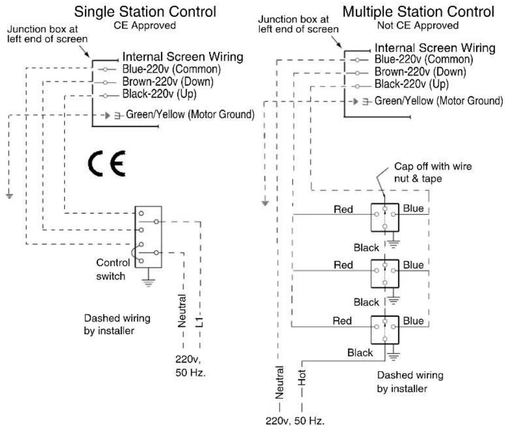
Junction box is located just above the closure panel, at the motor end of screen (left hand motor location only on Paragon). To properly remove closure panel, two people should follow the steps on page two of these instructions. The junction box access plate is held closed with pan head screws and may be opened with a Phillips screwdriver. Removal of access plate exposes brown, black and blue pigtail leads and green internal ground wire per attached wiring diagram. Screen is shipped with internal wiring complete and control switch(es) fully boxed. Wire connecting screen to switch(es) and switch(es) to power supply should be furnished by installer. Connections should be made in accordance with attached wiring diagram, and wiring should comply with national and local electrical codes.
All operating switches should be "off" before power is connected.
Please Note: Do not wire motors in parallel.
DRAPER
411 S. Pearl St., Spiceland, IN 47385 USA ■ 765-987-7999
www.draperinc.com ■ fax 765-987-1689
Copyright © 2014 Draper Inc. Form ParagonEV-220V_Inst14 Printed in U.S.A.
Operation
When screen is first operated, be cautious! Cycle unit down and up several times to confirm satisfactory operation.
220V AC Single Station Control—3-position up-off-down switch permits operation to be stopped at any point. Factory adjusted limit switches automatically stop screen when fully down or fully up.
220V AC Multiple Station Control (Not CE approved)—Switches are similar in appearance to 220 V AC Single Station Control. Screen stops when switch is released and may be restarted in either direction. Factory adjusted limit switches stop screen automatically when fully down or fully up.
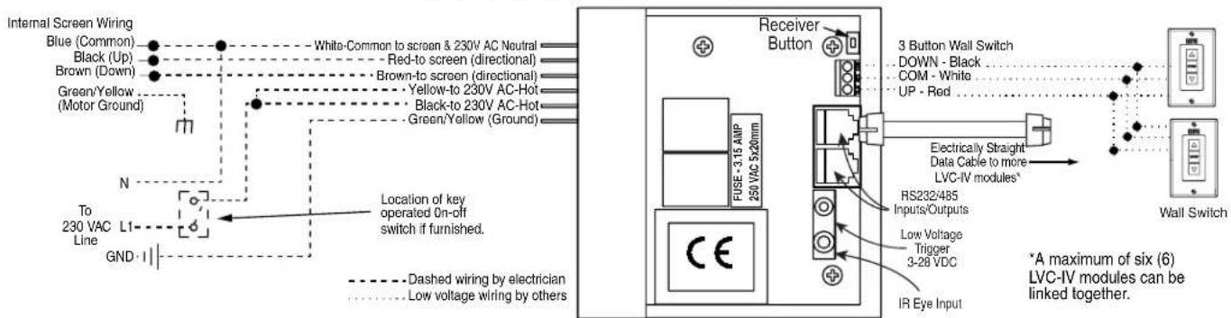
24V Control—Three-button up-stop-down switch(es) stop at any point desired, operate in any sequence. Factory adjusted limit switches automatically stop screen when fully down or fully up. Installer should incorporate an all-pole disconnect in the fixed wiring.
Key Operated Switching (Not CE approved)—Two kinds of key-operated switches are optionally available with this unit. ① The key-operated power supply switch controls power to the screen and switches. When it is "off", the switches will not operate screen. Key may be removed from the switch in either "on" or "off" position. ② A three-position key switch permits the screen to be operated directly by key. In this case, the screen's operator must always have a key.
RS232/Ethernet—Serial communication and network communication optionally available with wall switches, RF or IR remote.
Adjustments
Please Note: Screen limits are factory set for optimum performance of the screen. A procedure is outlined below for minor tweaks, but any adjustment of these limits may negatively affect the flatness of the screen surface and could also void the warranty. Please check with Draper prior to resetting screen limits.
△CAUTION: Always be prepared to shut screen off manually when new adjustment is being tested. Screen may be severely damaged if viewing surface is allowed to run too far up or too far down.
△CAUTION: Be sure all switches are in "off" position before adjusting limit switches.
Caution: Rough handling in transit may cancel/reset motor limit settings. To prevent viewing surface damage, be prepared to stop descending screen if surface begins to retract instead of stopping or if motor does not shut off when screen has fully retracted into case.
ADJUSTING "FULLY UP" POSITION—Put a small screw driver in the groove of the yellow button on the motor and press vertically until hearing a "click". Raise the screen by pressing the "up" switch on unit. Press the "stop" switch when the screen is at the desired position. Then press the yellow button on motor until you hear a "click", then release.
ADJUSTING "FULLY DOWN" POSITION—Put a small screw driver in the groove of the white button on the motor and press vertically until hearing a "click". Lower the screen by pressing the "down" switch on unit. Press the "stop" switch when the screen is at the desired position. Then press the white button on motor until you hear a "click", then release.
AT NO TIME SHOULD SCREEN BE UNROLLED ENOUGH TO EXPOSE ANY PART OF SCREEN ROLLER.
Suitable for use in environmental air space in accordance with Section 300-22(c) of the National Electrical Code, and Sections 2-128, 12-010(3) and 12-100 of the Canadian Electrical Code, Part 1, CSA C22.1.
Caution: Do not remove the roller assembly from the case unless necessary for repairs. If the roller assembly is removed, be sure motor is fully re-seated in the bracket, and re-secure it carefully with the motor retaining spring and screw (see diagram below).
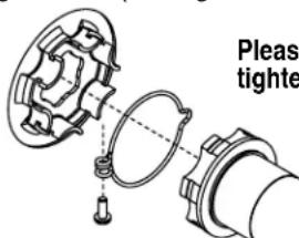
Please note: Maximum torque for tightening screw is 5 lb-inches.
Instructions
continued
on Page 2
Please see back page for dimensional diagrams of case and optional wall mounting bracket, wiring diagrams and instructions on removing and replacing the bottom closure.
If you encounter any difficulties installing or servicing your Paragon screen, call your dealer or Draper, Inc., Spiceland, Indiana, (765) 987-7999 or fax (765) 987-1689.
Paragon/Series E and V 220V by Draper
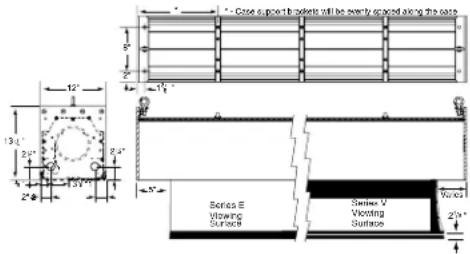
Case Dimensions\*
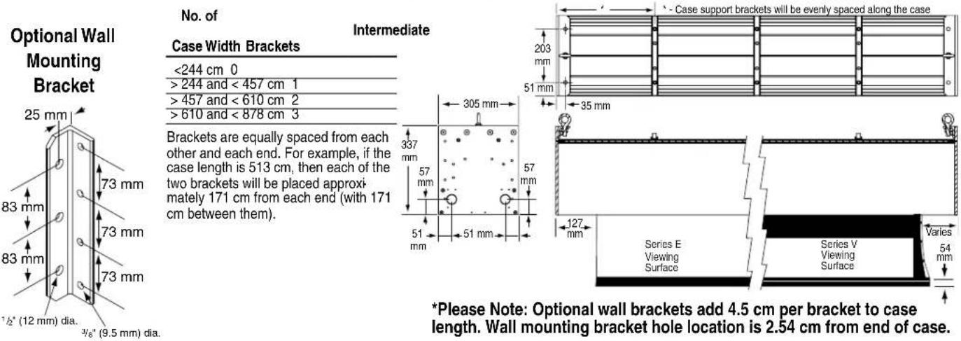
Case Width Brackets
| <244 cm 0 |
| >244 and < 457 cm 1 |
| >457 and < 610 cm 2 |
| >610 and < 878 cm 3 |
Brackets are equally spaced from each other and each end. For example, if the case length is 513 cm, then each of the two brackets will be placed approximately 171 cm from each end (with 171 cm between them).
*Please Note: Optional wall brackets add 4.5 cm per bracket to case length. Wall mounting bracket hole location is 2.54 cm from end of case.
Bottom Closure Removal/Replacement
Removal and replacement of the bottom closure panel requires two people positioned about 5' from each end of the panel. Closure should be handled as shown in Step 5 below to prevent bowing of the closure during handling.
Step 1
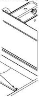
Before removing bottom closure, you must first remove screws at each end of case (see drawing at right).
natural_image
Technical line drawing of a mechanical assembly with no visible text or symbols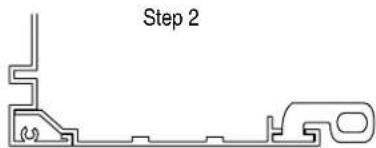
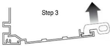
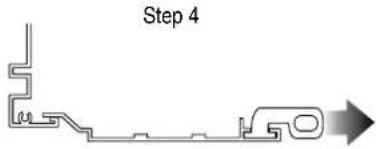
flowchart
graph LR
    A["Start"] --> B{Branch Point}
    B --> C["Process Step"]
    C --> D["Output Arrow"]
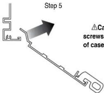
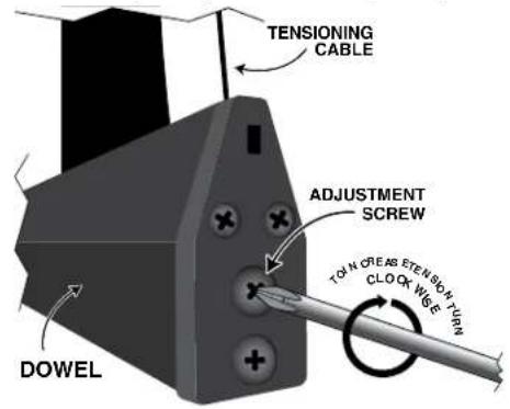
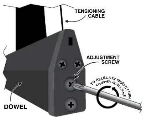
Tab-Tension Adjustment Procedure
Draper's Tab-Tensioning System is factory-set, and under normal circumstances will not require field adjustment. If, however, you notice wrinkles, waves or other indications that the tensioning cables need to be adjusted, follow the procedure below.
① Determine which side requires adjustment.
Caution: Do not touch or bend surface.
② Secure dowel with one hand.
③ Using Phillips-head screwdriver, depress spring-loaded adjustment screw and slowly turn CLOCKWISE TO INCREASE tension, or COUNTER-CLOCKWISE TO RELEASE tension. The screw adjusts in 14 turn increments. Adjust only one increment ( 14 turn) at a time.
④ If problem is not corrected, leave screen in position for 24 hours to allow surface material to stretch into position.
⑤ If problem still is not corrected, repeat steps 2 and 3.
Paragon/Series E and V 220V by Draper
Wiring Diagrams
Please Note: Do not wire motors in parallel.
Low Voltage and Remote Control
Brand : Draper
Model : Paragon E
Category : Projection screen