M635 - Laptop MSI - Free user manual and instructions
Find the device manual for free M635 MSI in PDF.

| Product Type | Laptop |
| Brand | MSI |
| Model | M635 |
| Screen Size | 15.6 inches |
| Processor | Intel Core i5 (typical) |
| RAM | 8 GB DDR4 |
| Storage | 256 GB SSD |
| Graphics | Integrated Intel UHD Graphics |
| Operating System | Windows 10 |
| Dimensions (W x D x H) | 357 x 247 x 23 mm |
| Weight | 2.2 kg |
| Power Supply | AC adapter 19V, 3.42A |
| Battery Life | Up to 5 hours |
| Connectivity | Wi-Fi 5, Bluetooth 4.2, USB 3.0, HDMI |
| Maintenance | Clean with dry soft cloth; avoid liquids |
| Safety | Keep away from heat sources; do not block vents |
| Spare Parts | Contact MSI support or authorized service centers |
| Repairability | RAM and storage upgradeable; battery replaceable |
| General Information | User manual available in PDF format |
Frequently Asked Questions - M635 MSI
User questions about M635 MSI
0 question about this device. Answer the ones you know or ask your own.
Ask a new question about this device
Download the instructions for your Laptop in PDF format for free! Find your manual M635 - MSI and take your electronic device back in hand. On this page are published all the documents necessary for the use of your device. M635 by MSI.
USER MANUAL M635 MSI
General Introductions
Chapter 2
Getting Started
Chapter 3
Customizing this Notebook
Chapter 4
BIOS setup
natural_image
Simple line drawing of a laptop computer with a clock icon (no text or symbols)Regulations Information
FCC-B Radio Frequency Interference Statement
This equipment has been tested and found to comply with the limits for a Class B digital device, pursuant to part 15 of the FCC rules. These limits are designed to provide reasonable protection against harmful interference in a residential installation. This equipment generates, uses and can radiate radio frequency energy and, if not installed and used in accordance with the instructions, may cause harmful interference to radio communications. However, there is no guarantee that interference will not occur in a particular installation. If this equipment does cause harmful interference to radio or television reception, which can be determined by turning the equipment off and on, the user is encouraged to try to correct the interference by one or more of the following measures:
w Reorient or relocate the receiving antenna.
w Increase the separation between the equipment and receiver.
w Connect the equipment into an outlet on a circuit different from that to which the receiver is connected.
w Consult the dealer or an experienced radio TV technician for help.
NOTE
- The changes or modifications not expressly approved by the party responsible for compliance could void the user's authority to operate the equipment.
- Shield interface cables and AC power cord, if any must be used in order to comply with the emission limits.
FCC Conditions
This device complies with part 15 of the FCC Rules. Operation is subject to the following two conditions:
- This device may not cause harmful interference.
- This device must accept any interference received, including interference that may cause undesired operation.

Micro-Star International
MS-1029/ M635

廢電池請回收
For better environmental protection, waste batteries should be collected separately for recycling or special disposal.
Safety Guideline for Using Lithium Battery
| (Danish) ADVARSEL! Lithiumbatteri --- Eksplosionsfare ved fejlagtighändtering. Udskiftning må kun ske med batteri af same fabrikat og type.Levé det brugte batteri tilbage til leverandøren. |
| (Deutsch) VORSICHT: Explosionsgefahr bei unsachgemäßem Austausch derBatterie. Ersatz nur durch denselben oder einen vom Hersteller empfohlenengleich-wertigen Typ. Entsorgung gebrauchter Batterien nach Angaben desHerstellers. |
| (English) CAUTION: Danger of explosion if battery is incorrectly replaced.Replace only with the same or equivalent type recommended by the equipmentmanufacturer. Discard used batteries according to manufacturer's instructions. |
| (Finnish) VAROITUS: Paristo voi räjähtää, jos se on virheellisesti asennettu.Vaihda paristo ainoastaan valmistajan suosittelemaan tyyppiin. Hävitä käytettyparisto valmistajan ohjeiden mukaisesti. |
| (French) ATTENTION: II y a danger d'ex;losion s'il y a remplacement incorrectde la batterie. Remplacer uniquement avec une batterie du meme type ou d'untype équivalent recommandé par le constructeur. Mettre au rebut les batteriesusages conformément aux instructions du fabricant. |
| (Norwegian) ADVARSEL: Eksplosjonsfare ved feilaktig skifte av batteri. Benyttsame batteritype eller en tilsvarende type anbefalt av apparatfabrikanten.Brukte batterier kasseres I henhold til fabrikantens instruksjoner. |
| (Swedish) WARNING: Explosionsfara vid felaktigt batteribyte. Använd sammabatterityp eller en ekvivalent typ som rekommenderas av apparattillverkaren.Kassera använt batteri enligt fabrikantens instruction. |
Caution on Using Modem
- Never install telephone wiring during a lightning storm.
- Never install telephone jacks in wet locations unless the jack is specifically designed for wet locations.
- Never touch uninsulated telephone wires or terminals unless the telephone line has been disconnected at the network interface.
- Use caution when installing or modifying telephone lines.
- Avoid using the telephone function (other than a cordless type) during an electrical storm. There may be a remote risk of electric shock from lightning.
- Do not use the telephone function to report a gas leak in the vicinity of the leak.
CD-ROM Drive Notice
CAUTION: This appliance contains a laser system and is classified as a "CLASS 1 LASER PRODUCT." To use this model properly, read the instruction manual carefully and keep this manual for your future reference. In case of any trouble with this model, please contact your nearest "AUTHORIZED service station." To prevent direct exposure to the laser beam, do not try to open the enclosure.
Safety Instructions
- Read the safety instructions carefully and thoroughly.
- Save this User Guide for possible use later.
- Keep this equipment away from humidity and high temperature.
- Lay this equipment on a stable surface before setting it up.
- The openings on the enclosure are used for air convection and to prevent the equipment from overheating. Do not cover the openings.
- Make sure that the power voltage is within its safety range and has been adjusted properly to the value of 100\~240V before connecting the equipment to the power inlet.
- Place the power cord in a way that people are unlikely to step on it. Do not place anything on the power cord.
- Always unplug the power cord before inserting any add-on card or module.
-
All cautions and warnings on the equipment should be noted.
-
If any of the following situations arises, get the equipment checked by a service personnel:
w The power cord or plug is damaged.
w Liquid has penetrated into the equipment.
w The equipment has been exposed to moisture.
w The equipment has not worked well or you can not get it work according to User's Manual.
w The equipment was dropped and damaged.
w The equipment has obvious signs of breakage.
- Never pour any liquid into the opening that could damage the equipment or cause an electrical shock.
- Do not leave the equipment in an unconditioned environment with a storage temperature of 60^ C ( 140^ F) or above, which may damage the equipment.
- To prevent explosion caused by improper battery replacement, use the same or equivalent type of battery recommended by the manufacturer only.
Trademarks
All trademarks are the properties of their respective owners.
w Microsoft is a registered trademark of Microsoft Corporation. Windows®98/ME, 2000/XP are registered trademarks of Microsoft Corporation.
w AMI ^® is a registered trademark of American Megatrends Inc.
w PCMCIA and CardBus are registered trademarks of the Personal Notebook Memory Card International Association.
Release History
| Version | Revision Note | Date |
| 1.0 | First Release | May 2005 |
Copyright Notice
The material in this guide is the intellectual property of MICRO-STAR INTERNATIONAL. We take every care in the preparation of this document, but no guarantee is given as to the correctness of its contents. Our products are under continual improvement and we reserve the right to make changes without notice.
Please note that the setting diagrams or values in this guide are FOR YOUR REFERENCE ONLY. The model you bought may be slightly different from the illustrations and descriptions in this guide. If you are not sure about these information, such as the Notebook specification and equipment, please ask your local vendor for help.
Technical Support
Visit the MSI website for FAQ, technical guide, driver and software updates, and other information: http://www.msi.com.tw/.
Contact our technical staff at: support@msi.com.tw.
Table of Content
Preface
Regulations Information ....II
FCC-B Radio Frequency Interference Statement ....II
FCC Conditions ...... II
Safety Guideline for Using Lithium Battery ....III
Caution on Using Modem....IV
CD-ROM Drive Notice....V
Safety Instructions ......VI
Trademarks......VIII
Release History......VIII
Copyright Notice....IX
Technical Support......IX
Introductions
How to Use This Manual 1-2
Unpacking 1-4
Getting Started
Specification....2-2
Product View 2-6
Top-open View 2-6
Front View....2-8
Right-side View....2-10
Left-side View 2-12
Rear View 2-13
Bottom View....2-15
Power Management 2-17
AC Adapter....2-17
Battery Pack 2-18
Using the Battery Pack....2-21
Basic Operations 2-23
Safety and Comfort Tips....2-23
Have a Good Work Habit 2-24
Knowing the Keyboard 2-25
Knowing the Touchpad 2-30
About Hard Disk Drive....2-34
Using the Optical Storage 2-35
Customizing this Notebook
Connecting the External Devices....3-2
Connecting the Peripheral Devices 3-3
Connecting the Communication Devices....3-6
PC Card Installation....3-7
Installing the PC card ....3-7
Removing the PC card 3-8
Safely Remove Hardware....3-9
BIOS Setup
About BIOS Setup....4-2
When to Use BIOS Setup 4-2
How to Run BIOS Setup....4-2
Control Keys 4-3
BIOS Setup Menu....4-4
Main menu 4-5
Advanced menu....4-7
Security menu....4-9
Boot menu....4-11
Exit menu 4-12
Preface
Chapter 1
General Introductions
Chapter 2
Getting Started
Chapter 3
Customizing this Notebook
Chapter 4
BIOS setup

natural_image
Simple line drawing of a laptop computer with a clock icon (no text or symbols)Congratulations on becoming a new user of this notebook, the finely designed notebook. This brand-new exquisite notebook will give you a delightful and professional experience in using notebook. We are proud to tell our users that this notebook is thoroughly tested and certified by our reputation for unsurpassed dependability and customer satisfaction.
How to Use This Manual
This User's Manual provides instructions and illustrations on how to operate this notebook. It is recommended to read this manual carefully before using this notebook.
Chapter 1. General Introductions, includes the descriptions of all the accessories of this notebook. It is recommended to check out that if you have all the accessories included when you open the packing box. If any item is damaged or missing, please contact the vendor where you purchased this notebook.
Chapter 2, Getting Started, provides the specification of this notebook, and introduces the function buttons, quick launch buttons, connectors, LEDs and externals of this notebook. Also, this chapter instructs the correct procedure of installing or uninstalling the battery pack, and the brief ideas on how to use this notebook.
Chapter 3. Customizing this Notebook, gives instructions not only in
connecting the mouse, keyboard, webcam, printer, external monitor, IEEE 1394 devices, and communication devices, but also in installing and removing the PC card.
Chapter 4, BIOS setup, provides information on BIOS Setup program and allows you to configure the system for optimum use.
Unpacking
First, unpack the shipping carton and check all items carefully. If any item contained is damaged or missing, please contact your local dealer immediately. Also, keep the box and packing materials in case you need to ship the unit in the future.
The package should contain the following items:
w Notebook
w User's Manual or Quick Start Guide
w Software CD containing the drivers and utilities
w Recovery CD
w High-capacity Li-ion battery pack
w AC adapter and power cord
w Phone cable/Phone jack (optional)
w Notebook carry bag (optional)
These accessories listed above may change without notice.
Preface
Chapter 1
General Introductions
Chapter 2
Getting Started
Chapter 3
Customizing this Notebook
Chapter 4
BIOS setup

natural_image
Simple line drawing of a laptop computer with a clock icon (no text or symbols)Specification
| Physical Characteristic | |
| Dimension | 355mm(L) x 255mm(D) x 30mm(H) |
| Weight | 2.8 kg |
| CPU | |
| Processor Type | 754-pin (uPGA) |
| Support Processor | Mobile Turion 64 25W seriesMobile Sempron 25W series |
| L1 Cache | 128K |
| L2 Cache | 1M/512K |
| FSB Speed | 266MHz |
| Socket | Socket N (754-pin) |
| Smart Power Management | Support AMD Power Now |
| Core Chips | |
| North Bridge | RX480M |
| South Bridge | SB400 |
| Memory | |
| Technology | DDR 400 |
| Memory | DDR SO-DIMM X 2 slot128/256/512/1024MB DDR SDRAM |
| Maximum | 2GB (1024MB DDR SO-DIMM X 2) |
| Power | |
| AC Adapter | 90W, 19 Volt |
| Battery Typel | 8 cells (Li-Ion) (4400mAh / 4800mAh), appx. 3.0 hrs |
| RTC Battery | Yes, 3 years |
| Storage | |
| HDD form factor | 9.5mm(H), 40/60/80GB |
| IDE Controller | Ultra DMA ATA-100 |
| Optical Device | DVD-ROM/COMBO/DVD dual |
| I/O Port | |
| Monitor(VGA) | 15 pin Mini D-Sub x 1 |
| USB | x 4 (USB version 2.0) |
| Consumer IR | x 1 |
| Mic-in | x 1 |
| Headphone Out | x 1 (SPDIF-Out supported) |
| RJ11 | x 1 |
| RJ45 x 1 | |
| TV-Out | x 1 (S-Video) |
| Communication Port | |
| 56K Fax/MODEM | I/F --- AC97 S/W Modem |
| MDC (AC'97) | Controller --- AC 97 EmbeddedWake on Ring --- Support on S1/S2/S3statePTT Approval --- Yes (FCC/CTR21/JATE) |
| LAN | PHY --- Realtek 8201Wake on LAN --- Support on S3LAN Boot --- YesWfm --- Wfm 2.0 support |
| Wireless LAN | IEEE 802.11b/g |
| PCMCIA | |
| Controller | RICOH R5C593 |
| Slot | Type II x 1 |
| CardBus | Support |
| Display | |
| LCD Type | 15.4" WXGA |
| Brightness | Brightness controlled by K/B hot-keys |
| Video | |
| Controller | ATI M26 |
| VRAM 64/128MB | |
| LCD | 1280 x 800 WXGA |
| CRT Support | 640x480, max, 32bit color800x600, max, 32bit color1024x768, max, 32bit color1400x1050, max, 32bit color |
| Audio | |
| Sound Controller | SB400 |
| Sound Codec chip | Realtek ALC658 |
| Internal Speaker | 2 Speakers with housing |
| SoundBlaster | SoundBlaster compatible(Not support DOS) |
| Sound Volume | Adjust by volume button, K/B hot-key & SW |
| Software & BIOS | |
| Support OS | Win XP Home and Professional edition |
| USB Flash Boot | Yes, USB floppy boot up DOS only |
| BIOS | Fast Boot Support --- Yes (Win XP) |
| Others | |
| Remote Controller | Yes |
| Kensington Lock Hole | x 1 |
Product Overview
This section provides you the description of basic aspects of your Notebook. It will help you to know more about the appearance of this Notebook before using it.
Top-open View
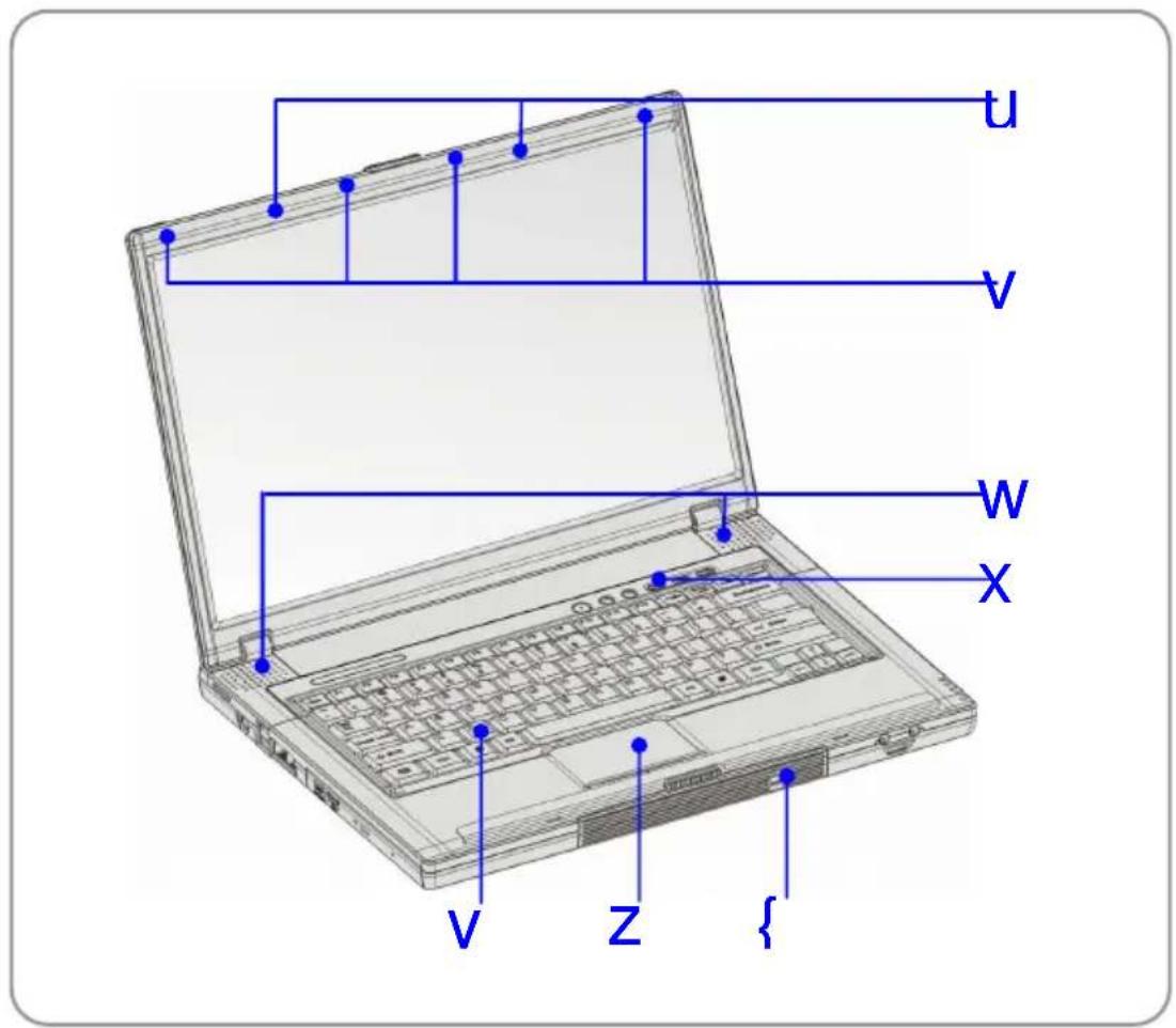
Press the Cover Latch to open the top cover (LCD Panel). The figure of top-open view and description showing below will lead you to browse the main operating area of your NOTEBOOK.
text_image
U V W X V Z {1. Cover Latch (Internal View)
It is a bounce-back device to lock the cover with the deck when closing your Notebook PC.
2. Rubber Pads
Protect your Notebook PC from random closing.
3. Stereo Speakers
Make high quality sound blaster with stereo system and Hi-Fi function supported.
4. Quick Launch Buttons and Power Button
5. Keyboard
The built-in keyboard provides all the functions of a full-sized 86-key (US-defined) keyboard.
6. Touchpad
It is the pointing device of the computer.
7. IEEE 1394
The IEEE 1394 port is a high-speed bus that allows you to connect high-end digital devices such as the DV (digital video camera).
Front View

text_image
U W X V1. Cover Latch (External View)
Press Cover Latch rightward and lift the cover. The Cover Latch will bounce back when loosing it.
2. IEEE 1394
The IEEE 1394 port is a high-speed bus that allows you to connect high-end digital devices such as the DV (digital video camera).
3. Audio Port Connectors
Make high quality sound blaster with stereo system and Hi-Fi function supported.
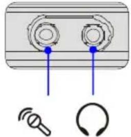 |  | Line In: Used for external CD player, Tape recorder or other audio devices |
 | Line Out: A connector for speakers or headphones. |
4. Consumer Infrared
It is used to transfer the Remote Controller signal to control the device.
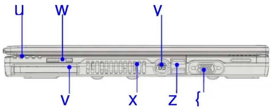
Right-side View
text_image
U W V V X Z {1. Status LED
 | Battery: Glowing Green when recharging.Battery LED goes out when recharging is done or when the AC adapter is disconnected.Glowing Orange when the battery is in low battery status.Blinking Orange if the battery is out of order, and it is recommended to replace a new battery. |
 | Num Lock: Glowing Green when the Num Lock function is activated. |
 | Caps Lock: Glowing Green when the Caps Lock function is activated. |
 | Hard Disk In-use: Blinking Green when the Notebook is accessing the hard disk drive. |
 | Wireless LAN: Glowing Blue when wireless LAN function of the computer is enabled. LED goes out when wireless LAN function is disabled. |
2. PC Card Slot
The computer provides a PC card slot to support one Type-II PC card for expansion functions, such as LAN/WLAN card, modem card, memory card, etc.
3. 3 in 1 Card Reader
The built-in card reader supports MMC (multi-media card), SD (secure digital) and MS (memory stick) cards
4. Ventilator
The ventilator is designed to cool the system. DO NOT block the ventilator for air circulation.
5. S-Video Connector
By using a Super VHS (S-Video) cable, this connector allows you to connect a television (NTSC/PAL system) to use as a computer display.
6. USB Port
The USB 2.0 port allows you to connect USB-interface peripheral devices, such as the mouse, keyboard, modem, portable hard disk module, printer and more.
7. VGA Port
The 15-pin-D-sub VGA port allows you to connect an external monitor or other standard VGA-compatible device (such as a projector) for a great view of the computer display.
Left-side View

text_image
U W V V X Z1. Stereo Speakers
Make high quality sound blaster with stereo system and Hi-Fi function supported.
2. Power Connector
To connect the AC adapter and supply power for the computer.
3. USB Port
The USB 2.0 port allows you to connect USB-interface peripheral devices, such as the mouse, keyboard, modem, portable hard disk module, printer and more.
4. RJ-45 Connector
The 100/10 Ethernet connector is used to connect a LAN cable for network connection.
5. RJ-11 Connector
The computer provides a built-in modem that allows you to connect an FJ-11 telephone line through this connector. With the 56K V.90 modem, you can make a dial-up connection.
6. Optical Storage Device
A slim CD-ROM/DVD-ROM/CD-RW/DVD Combo/DVD Dual drive is available in the computer, depending on the model you purchased. The optical device allows you to use the CD/DVD disc for installing software, accessing data and playing music/movie on the computer.
Rear View

text_image
U V1. Kensington Lock
This port is used to lock the computer to location for security.
2. Battery Pack (Rear View)
To supply power to your computer when the AC adapter is not connected.
Bottom View
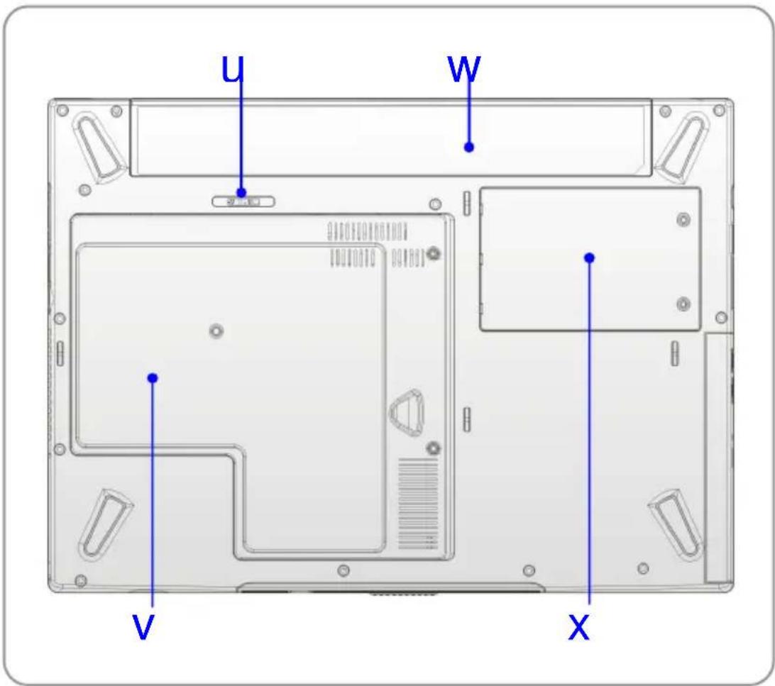
text_image
U W V X1. Battery Release Button
It is a bounce-back device as a preparation for releasing the battery pack. Press it with one hand and pull the battery pack carefully with the other.
2. Mini PCI, Memory, CPU Compartment
Mini PCI slot -- The built-in wireless LAN card of the computer is installed in this compartment.
CPU slot – This compartment includes the Central Processor Unit and the Ventilator unit
Memory Slot -- This compartment also includes two SO-DIMM slots for expanding the memory size up to 2GB.
Please note that the memory installation/replacement must be done by an authorized retailer.
3. Battery Pack
Supply power to your computer when the AC adapter is not connected.
4. HDD Compartment
Inside this compartment is the Hard Drive.
Power Management
AC Adapter
Please be noted that it is strongly recommended to connect the AC adapter and use the AC power while using this Notebook for the first time. When the AC adapter is connected, the battery is being charged immediately.
NOTE that the AC adapter included in the package is approved for your Notebook; using other adapter model may damage the Notebook or other devices on the Notebook.
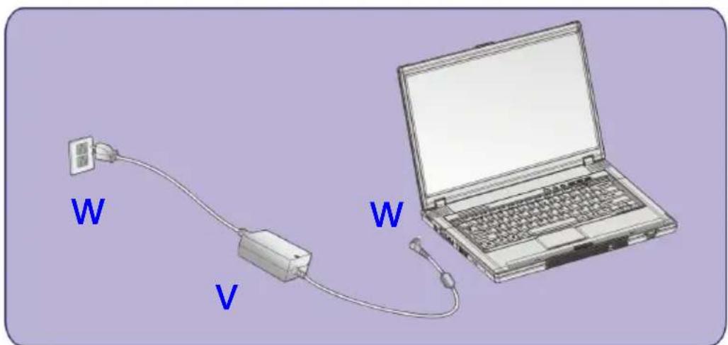
Connecting the AC Power
- Unpack the package to find the AC adapter and power cord.
- Attach the power cord to the connector of the AC adapter.
- Plug the DC end of the adapter to the Notebook, and the male end of the power cord to the electrical outlet.
text_image
W V WDisconnecting the AC Power
When you disconnect the AC adapter, you should:
- Unplug the power cord from the electrical outlet first.
- Unplug the connector from the Notebook.
- Disconnect the power cord and the connector of AC adapter.
- When unplugging the power cord, always hold the connector part of the cord. Never pull the cord directly!
Battery Pack
This Notebook is equipped with a high-capacity 4-cell/8-cell Li-ion Battery pack. The rechargeable Li-ion battery pack is an internal power source of the Notebook. A fully charged battery pack can supply power to the Notebook approximately up to 1.5 hours (using 4-cell battery) or up to 3 hours (using 8-cell battery). It depends on the way you use the Notebook.
Releasing the Battery Pack
It's a better way to have extra battery for enough power supply, so you don't have to worry about the lack of battery power. It's recommend to buy a battery pack from your local dealer.
To remove the battery pack:
- Make sure the computer is turned off.
- Locate the Battery Release Button on the bottom side. Push the Release Button to the direction of arrow showing below the button.
- Slide the left side of the battery pack first out of the compartment and then pull the right side of the battery pack.

text_image
W W V 200000 198000 196000 194000 192000 190000 188000 186000 184000 182000 180000 178000 176000 174000 172000 170000 168000 166000 164000 162000 160000 158000 156000 154000 152000 150000 148000 146000 144000 142000 140000 138000 136000 134000 132000 130000 128000 126000 124000 122000 120000 118000 116000 114000 112000 110000 108000 106000 104000 102000 100000 98000 96000 94000 92000 90000 88000 86000 84000 82000 80000 78000 76000 74000 72000 70000 68000 66000 64000 62000 60000 58000 56000 54000 52000 5000 52555555555555555555555555555555555555555555555555555555555555555555555555555Replacing the Battery Pack
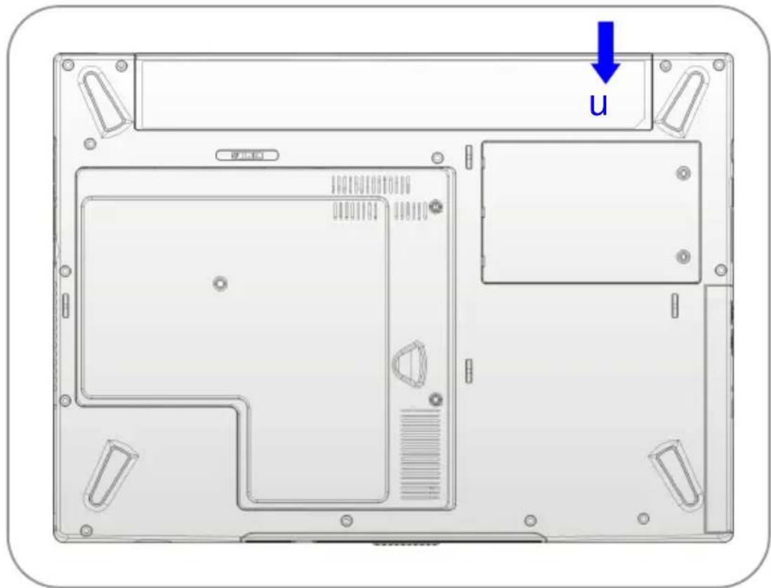
- Insert the right side of battery pack into the compartment.
- Slightly slide and press the battery pack into the right place.
- After the right side of the battery pack fitting the right track, then slightly press the left side of battery pack into the battery chamber.
text_image
U 更正贴info
Warning
- Do not try to disassemble THE BATTERY PACK.
- Please follow your local laws and regulations to recycle the unused battery pack.
Using the Battery Pack
Battery Safety Tips
Replacing or handling the battery incorrectly may present a risk of fire or explosion, which could cause serious injury.
w Only replace the main battery pack with the same or equivalent type of battery.
w Do not disassemble, short-circuit or incinerate batteries or store them to temperatures above +60°C (+140°F).
w Do not temper with batteries. Keep them away from children.
w Do not use rusty or damaged batteries.
w Dispose of batteries according to local regulations. Check with your local solid waste officials for details about recycling options or for proper disposal in your area.
Conserving Battery Power
Efficient battery power is critical to maintain a normal operation. If the battery power is not managed well, the saved data and customized settings may be lost.
Follow these tips to help optimizing battery life and avoid a sudden power loss.
w Suspend system operation if the system will be idle for a while or shorten the Suspend Timer's time period.
w Turn off the system if you won't be using it for a period of time.
w Disable unneeded settings or remove idle peripherals to conserve power.
w Connect an AC adapter to the system whenever possible.
Charging the Battery Pack
The battery pack can be recharged while it is installed in the Notebook. Please pay attention to the following tips before recharging the battery:
w If a charged battery pack is not available, save your work and close all running programs and shut down the system or Save-to-Disk.
w Plug in an external AC/DC power source.
w You can use the system, suspend system operation or shut down and turn off the system without interrupting the charging process.
w The battery pack uses Lithium-ion battery cells that have no “memory effect.” You do not need to discharge the battery pack before you begin charging. However, to optimize the life of battery, we suggest that consuming the battery power completely once a month is necessary.
w If you do not use the Notebook for a long time, it is suggested to remove the battery pack from your Notebook. This may be helpful to extend your battery life.
w The actual charging time will be determined by the applications in use.
Basic Operations
If you are a beginner to the Notebook, please read the following tips to make yourself safe and comfortable during the operations.
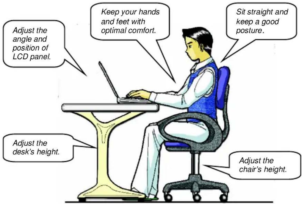
Safety and Comfort Tips
The Notebook is a portable platform that allows you to work anywhere. However, choosing a good workspace is important if you have to work with your Notebook for long periods of time.
w Your work area should have enough illumination.
w Choose the proper desk and chair and adjust their height to fit your posture when operating.
w When sitting on the chair and adjust the chair's back (if available) to support your back comfortably.
w Place you feet flat and naturally on the floor, so that your knees and elbows have the proper position (about 90-degree) when operating.
w Put your hands on the desk naturally to support your wrists.
w Adjust the angle/position of the LCD panel, so that you can have the optimal view.
w Avoid using your Notebook in the space where may cause your discomfort (such as on the bed).
w The Notebook is an electrical device, please treat it with great care to avoid personal injury.
text_image
Adjust the angle and position of LCD panel. Keep your hands and feet with optimal comfort. Sit straight and keep a good posture. Adjust the desk's height. Adjust the chair's height.Have a Good Work Habit
Have a good work habit is important if you have to work with your Notebook for long periods of time; otherwise, it may cause discomfort or injury to you. Please keep the following tips in mind when operating.
w Change your posture frequently.
w Stretch and exercise you body regularly.
w Remember to take breaks after working for a period of time.
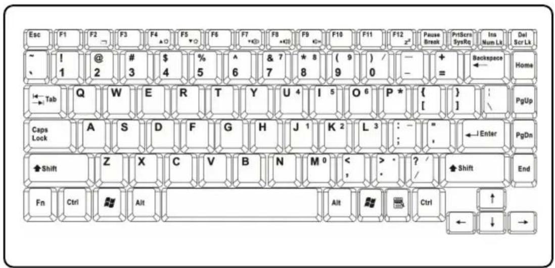
Knowing the Keyboard
The Notebook's keyboard provides all the functions of a full-sized 86-key keyboard and an additional [Fn] key for specific functions on the Notebook. The keyboard can be divided into four categories: Typewriter keys, Cursor keys, Numeric keys and Function keys.
text_image
Esc F1 F2 → F3 F4 ▲ F5 ▼ F6 F7 +K0 F8 +K0 F9 G→ F10 F11 F12 x² Pause Break PrtScr SysRq Ins Num Lk Del Scr Lk ~ ! 1 @ 2 # 3 $ 4 % 5 ^ 6 & 7 7 * 8 ( 9 ) / - + = Backspace Home ← Tab Q W E R T Y U 4 I 5 O 6 P * { } : PgUp Caps Lock A S D F G H J 1 K 2 L 3 : - " ←Enter PgDn Shift Z X C V B N M 0 < > · ? / Shift End Fn Ctrl Alt Alt Ctrl ↑ ↓ → ← ↓ →Typewriter Keys

text_image
Esc ~ 1 @ 2 # 3 $ 4 % 5 ^ 6 & 7 7 * 8 ( 9 ) / - + = Backspace Tab Q W E R T Y U 4 I 5 O 6 P * { } :\ Caps Lock A S D F G H J 1 K 2 L 3 : - " , ←Enter Shift Z X C V B N M 0 < , > · ? / Shift Ctrl Alt Alt Ctrl Typewriter Keys Ins Num Lt Del Scr LtThe function of these Typewriter keys is the major function of the keyboard, which is similar to the keys on a typewriter. It also provides several keys for special purposes, such as the [Ctrl], [Alt] and [Esc] key.
When the lock keys are pressed, the corresponding LEDs will light up to indicate their status:
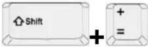
n Num Lock: Press and hold the [Fn] key and press this key to toggle the Num Lock on and off. When this function is activated, you can use the numeric keys that are embedded in the typewriter keys.
n Caps Lock: Press this key to toggle the Caps Lock on and off. When this function is activated, the letters you type are kept in uppercase.
n Scroll Lock: Press and hold the [Fn] key and press this key to toggle the Scroll Lock on and off. This function is defined by individual programs, and it is usually used under DOS.
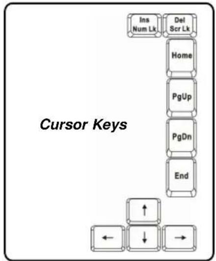
Cursor Keys
The keyboard provides four cursor
(arrow) keys and [Home], [PgUp], [PgDn],
[End] keys at the lower right corner,
which are used to control the cursor
movement.
text_image
Cursor Keys Ins Num Lk Del Scr Lk Home PgUp PgDn End ← ↓ → | Move the cursor left for one space. |
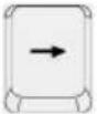 | Move the cursor right for one space. |
 | Move the cursor up for one line. |
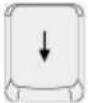 | Move the cursor down for one line. |
 | Move to the previous page. |
 | Move to the next page. |
 | Move to the beginning of the line (or document). |
 | Move to the end of the line (or document). |
The Backspace key, [Ins] and [Del] keys at upper right corner are use for editing purpose.
 | This key is used to switch the typing mode between “insert” and “overtype” modes. |
 | Press this key to delete one character to the right of the cursor and move the following text left for one space. |
 | Press this key to delete one character to the left of the cursor and move the following text left for one space. |
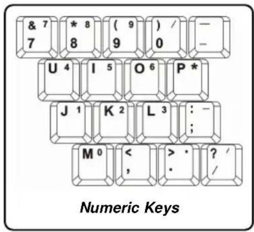
Numeric Keys
The keyboard provides a set of numeric keypad, which is embedded in the typewriter keys. When the Num Lock is activated, you can use these numeric keys to enter numbers and calculations.
text_image
& 7 7 * 8 8 ( 9 ) 9 )/ 0 — — U 4 I 5 O 6 P * J 1 K 2 L 3 : - ; M 0 < >, >. ? / / Numeric KeysFunction Keys
n Windows Keys
You can find the Windows Logo key ( ) and one Application Logo key ( ) on the keyboard, which are used to perform Windows-specific functions, such as opening the Start menu and launching the shortcut menu. For more information of the two keys, please refer to your Windows manual or online help.
n [Fn] Key
![MSI M635 - n [Fn] Key - 1](/content/2026/05/975063/images/03ccdbdd657277477ab9effda487de33bf1f829a69e2da108d306c801a9a66a3.jpg) | Switch the display output mode between the LCD, external monitor and Both. |
![MSI M635 - n [Fn] Key - 2](/content/2026/05/975063/images/3c833ea55eec99e888c51e3ea9205bacbd5054a04ecc1c834f19b2de602a8eb4.jpg) | Increase the LCD brightness. |
![MSI M635 - n [Fn] Key - 3](/content/2026/05/975063/images/2252f8176e418e2b83d35817d8f818a87835725d6293cb81e92cba9536786f0e.jpg) | Decrease the LCD brightness. |
![MSI M635 - n [Fn] Key - 4](/content/2026/05/975063/images/bacd67df48f6310cdc99d524092c26b5fdb895cbb5a81a4a79992650f3ed0502.jpg) | Decrease the built-in speaker's volume. |
![MSI M635 - n [Fn] Key - 5](/content/2026/05/975063/images/84cb4e2860a7a1c7363a2991b5e97cf40584958b2d1e665fb610c7578c49ce20.jpg) | Increase the built-in speaker's volume. |
![MSI M635 - n [Fn] Key - 6](/content/2026/05/975063/images/784590790addc7890b6eb6182f2fb550006fdff0be0c2b07c7f1850b8fe05dd4.jpg) | Disable the Notebook's audio function. |
![MSI M635 - n [Fn] Key - 7](/content/2026/05/975063/images/cfa37d83ecf6a73e97021cc2e28963657cbc191df7ef85afeff598d88456791a.jpg) | Force the Notebook into suspend mode (depending on the system configuration). |
Knowing the Touchpad
The touchpad integrated in your Notebook is a pointing device that is compatible with standard mouse, allowing you to control the Notebook by pointing the location of the cursor on the screen and making selection with its two buttons.

text_image
U V W1. Cursor Movement Area
This pressure-sensitive area of the touchpad, allows you to place your finger on it and control the cursor on the screen by moving your finger.
2. Right Button
Acts as the mouse's right button.
3. Left Button
Acts as the mouse's left button.
Using the Touchpad
Read the following description to learn how to use the touchpad:
n Positioning and Moving
Place your finger on the touchpad (usually using the forefinger), and the rectangular pad will act as a miniature duplicate of your display. When you move your fingertip across the pad, the cursor on the screen will move simultaneously in the same direction. When your finger reaches the edge of the pad, lift your finger and replace it on a proper location of the touchpad.
n Point and Click
When you have moved and placed the cursor over an icon, a menu item or a command that you want to execute, simply tap slightly on the touchpad or press the left button to select. This procedure, called as point and click is the basics of operating your Notebook. Unlike the traditional pointing device such as the mouse, the whole touchpad can act as a left button, so that your each tap on the touchpad is equivalent to pressing the left button. Tapping twice more rapidly on the touchpad is to execute a double-click.
n Drag and Drop
You can move files or objects in your Notebook by using drag-and-drop. To do so, place the cursor on the desired item and slightly tap twice on the touchpad, and then keep your fingertip in contact with the touchpad on the second tap. Now, you can drag the selected item to the desired location by moving your finger on the touchpad, and then lift your finger from the touchpad to drop the item into place. Alternately, you can press and hold the left button when you select an item, and then move your finger to the
desired location; finally, release the left button to finish the drag-and-drop operation.
Using the Touchpad
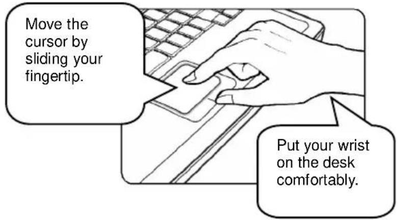
text_image
Move the cursor by sliding your fingertip. Put your wrist on the desk comfortably.n Configuring the Touchpad
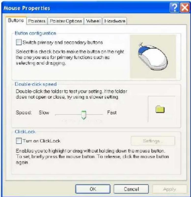
You can customize the pointing device to meet your personal needs. For example, if you are a left-hand user, you may want to swap the functions of the two buttons. In addition, you can change the size, shape, moving speed and other advanced features of the cursor on the screen.
To configure the touchpad, you can use the standard Microsoft or IBM PS/2 driver in your Windows operating system. The Mouse Properties in Control Panel allows you to change the configuration.
text_image
Mouse Properties Buttons Painters Pointer Options Wheel Hardware Button configuration Switch primary and secondary buttons Select this check box to make the button on the right the one you use for primary functions such as selecting and dragging. Double-click speed Double-click the folder to test your setting. If the folder does not open or close, try using a slower setting. Speed: Slow Fast ClickLock Turn on ClickLock Settings... Enables you to highlight or drag without holding down the mouse button. To set, briefly press the mouse button. To release, click the mouse button again. OK Cancel ApplyMouse Properties Window
About Hard Disk Drive
Your Notebook is equipped with a 2.5-inch IDE (Integrated Drive Electronics) hard disk drive. The hard disk drive is a storage device with much higher speed and larger capacity than other storage devices, such as the floppy disk drive and optical storage devices. Therefore, it is usually used to install the operating system and software applications.
info
- To avoid unexpected data loss in your system, please backup your critical files regularly.
- Do not turn off the Notebook when the Hard Disk In-use LED is on.
- Do not remove or install the hard disk drive when the Notebook is turned on. The replacement of hard disk drive should be done by an authorized retailer or service representative.
Using the Optical Storage
Your Notebook is equipped with an optical storage device, which is known as the CD/DVD-ROM, CD-RW, DVD Combo and DVD Dual drive. The actual device installed in your Notebook depends on the model you purchased.
n CD-ROM Drive: Allows you to read CD disks, including audio CDs and CD-R/RW disks.
n DVD-ROM Drive: Allows you to read DVD disks and CD disks, including movie DVDs, audio CDs and CD-R/RW disks.
n CD-RW Drive: Allows you to create the CD-R/RW disks containing your own contents.
n DVD Combo Drive: A cost-effective solution that can work both as a DVD-ROM drive and a CD-RW drive.
n DVD Dual Drive: A dual format recorder, allows you to record both the -R/RW and +R/RW formats.
info
-
The optical storage devices are classified as a Class 1 Laser products. Use of controls or adjustments or performance of procedures other than those specified here in may result in hazardous radiation exposure.
-
Do not touch the lens inside the drive.
Inserting the CD
The following instruction describes the general procedure when operating the optical storage device, including the DVD-ROM drive.
- Confirm that the Notebook is turned on.
- Press the Eject Button on the drive's panel and the CD tray will slide out partially. Then, gently pull the tray out until fully extended.
- Place your CD in the tray with its label facing up. Slightly press the center of the CD to secure it into place.
- Push the tray back into the drive.
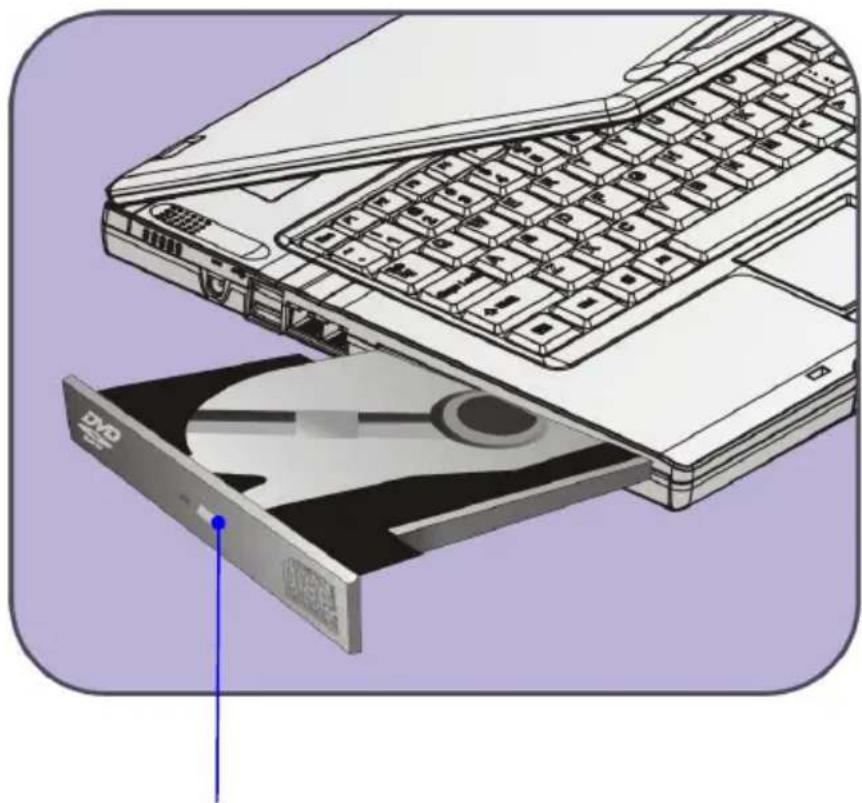
natural_image
Illustration of a laptop keyboard and an open CD/DVD drive, showing internal components (no text or symbols)Eject Button
Removing the CD
- Press the Eject Button on the drive's panel and the CD tray will slide out partially. Then, gently pull the tray out until fully extended.
- Hold the CD by its edge with your fingers and lift it up from the tray.
- Push the tray back into the drive.
info
- Confirm that the CD is placed correctly and securely in the tray before closing the tray.
- Do not leave the CD tray open.
Preface
Chapter 1
General Introductions
Chapter 2
Getting Started
Chapter 3
Customizing this Notebook
Chapter 4
BIOS setup

natural_image
Simple line drawing of a laptop computer with a circular button at the bottom right (no text or symbols)Connecting the External Devices
The I/O (input/output) ports on the Notebook allow you to connect peripheral devices.
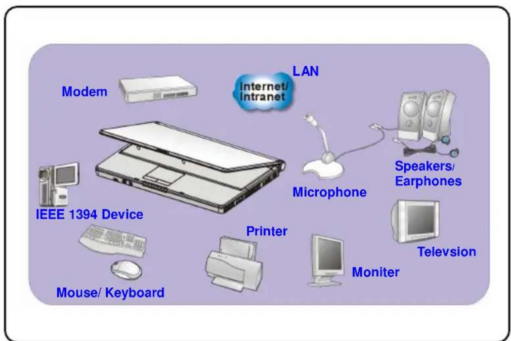
text_image
Modem Internet/ intranet LAN Microphone Speakers/ Earphones IEEE 1394 Device Printer Mouse/ Keyboard Monitor TelevisionConnecting the Peripheral Devices
Connecting the Mouse
You can connect a mouse to your Notebook through the PS/2 port or USB port. If there is no PS/2 port available on your Notebook, but you only have mouse of PS/2 connector, please purchase a PS/2-USB connector first. To connect the mouse:
- Turn on the Notebook and install the mouse driver.
- Connect your mouse to the Notebook.
- The Notebook may auto detect your mouse driver and enable the mouse function. If there is no detection of you mouse you can manually enable the mouse by going to Start Menu ± Control Panel ± Add Hardware to add the new device.
Connecting the Keyboard
You can connect a keyboard to your Notebook through the PS/2 port or USB port. If there is no PS/2 port available on your Notebook, but you only have mouse of PS/2 connector, please purchase a PS/2-USB connector first. To connect the keyboard:
- Turn on the Notebook and install the keyboard driver.
- Connect your keyboard to the Notebook.
- The Notebook may auto detect your keyboard driver and enable the keyboard function. If there is no detection of you keyboard you can manually enable the keyboard by going to Start Menu + Control Panel + Add Hardware to add the new device.
Connecting the WebCam
You can connect a WebCam to your Notebook through the USB port. To connect the WebCam:
- Turn on the Notebook and install the WebCam driver.
- Connect your WebCam to the Notebook.
- The Notebook may auto detect your WebCam driver and enable the WebCam function. If there is no detection of you WebCam you can manually enable the WebCam by going to Start Menu # Control Panel # Add Hardware to add the new device.
Connecting the Printer
If your printer has a USB interface, you can then use the USB port on the Notebook to connect the printer. The following instruction describes the general procedure to connect a printer:
- Turn off the Notebook.
- Connect one end of the printer cable to the Notebook's USB port and the other end to the printer.
- Connect the power cord and turn on the printer.
- Turn on the Notebook and the system will detect a new device. Install the required driver.
For further instructions, please refer to your printer's manual.
Connecting the External Monitor or TV
You can connect an external monitor to your Notebook through the VGA port for a larger view with higher resolution. To connect the monitor:
-
Make sure that the Notebook is turned off.
-
Plug the monitor's D-type connector into the Notebook's VGA port.
- Connect the monitor's power cord and turn on the monitor.
- Turn on the Notebook and the monitor should respond by default. If not, you can switch the display mode by pressing [Fn]+[F2]. Alternately, you can change the display mode by configuring the settings in Display Properties of Windows operating system.
Connecting the IEEE 1394 devices
The IEEE 1394 port of your Notebook is a next-generation serial bus that features a high-speed transfer rate and the connection of up to 63 devices, allowing you to connect many high-end peripheral devices and consumer electronic appliances, such as the DV (digital video camera). The IEEE 1394 standard interface supports “plug-and-play” technology, so that you can connect and remove the IEEE 1394 devices without turning off the Notebook.
To connect the IEEE 1394 device, simply connect the cable of the device to the IEEE 1394 port of your Notebook.
Connecting the Communication Devices
Using the LAN
The RJ-45 connector of the Notebook allows you to connect the LAN (local area network) devices, such as a hub, switch and gateway, to build a network connection. This built-in 10/100 Base-T LAN module supports data transfer rate up to 100Mbps.
For more instructions or detailed steps on connecting to the LAN, please ask your MIS staff or network manager for help.
Using the Modem
The built-in 56Kbps fax/data modem allows you to use a telephone line to communicate with others or to dial-up to connect the Internet.
For more instructions or detailed steps on dialing-up through the modem, please consult your MIS staff or Internet service provider (ISP) for help.
info
- To reduce the risk of fire, use only No. 26 AWG or larger telecommunication lone cord.
- You are strongly recommended to install the modem driver included in the software CD of your Notebook to take full advantage of the modem feature.
PC Card Installation
The PC card slot of your Notebook allows you to install comprehensive Type-II PC cards that support various functions for your necessary, including the LAN/WLAN card, modem card and memory card.
The following instruction provides you with a basic installation for the PC card, including how to install and remove it. For more information, please refer to the manual of your PC card.
Installing the PC card
- Locate the PC card slot on your notebook Notebook. If there is the dummy card in the slot, remove it first.
- Insert the PC card into the slot (usually with its label facing up) and push it until it is firmly seated.

natural_image
Illustration of a computer tower with a red arrow pointing to a device attachment (no text or symbols present)Removing the PC card
- Press the Eject Button to make it stretch out.
- Push the Eject Button and the PC card will slide out. Pull it out of the slot.
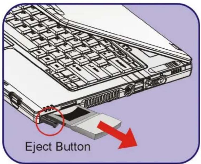
text_image
Eject Buttoninfo
- Do not hold the "golden finger" when installing the PC card; otherwise, it may cause interference or damage to the PC card.
- Before removing the PC card, you should stop the device in Windows operating system.
Safely Remove Hardware
If you connect any peripheral device to your system, the Safely Remove Hardware icon ( ) will appear on the taskbar. Double-click the icon to bring up the Safely Remove Hardware dialog box. You can see all connected peripheral devices here. If you want to remove any of the devices, move the cursor to the device and click Stop.

text_image
Safely Remove Hardware Select the device you want to unplug or eject and then click Stop. When Windows notifies you that it is safe to do so unplug the device from your computer. Hardware devices: USB Mass Storage Device 802.11g CordBus Wireless Network Adapter USB Mass Storage Device at Location 0 Properties Stop Display device components Close Stop a Hardware device Confirm devices to be stopped. Choose OK to continue. Windows will attempt to stop the following devices. After the devices are stopped they may be removed safely. USB Mass Storage Device Generic volume - (E.) Walking Disk USB Device OK CancelPrefeace
Chapter 1
General Introductions
Chapter 2
Getting Started
Chapter 3
Customizing this Notebook
Chapter 4
BIOS setup

natural_image
Simple line drawing of a laptop computer with a circular button at the bottom right (no text or symbols)About BIOS Setup
When to Use BIOS Setup?
You may need to run the BIOS Setup when:
w An error message appears on the screen during the system booting up and requests you to run SETUP.
w You want to change the default settings for customized features.
w You want to reload the default BIOS settings.
How to Run BIOS Setup?
To run the BIOS Setup Utility, turn on the Notebook and press the [Del] key during the POST procedure.
If the message disappears before you respond and you still wish to enter Setup, restart the system by turning it OFF and ON, or simultaneously pressing [Ctrl]+[Alt]+[Delete] keys to restart.
info
The screen snaps and setting options in this chapter are for your references only. The actual setting screens and options on your Notebook may be different because of BIOS update.
Control Keys
You can use only the keyboard to control the cursor in the BIOS Setup Utility.
 | Press left arrow to select one menu title. |
 | Press right arrow to select one menu title. |
 | Press up arrow to select one item under the menu title. |
 | Press down arrow to select one item under the menu title. |
 | Increase the setting value or make changes. |
 | Decrease the setting value or make changes. |
 | 1) Open the selected item to change setting options.2) Bring up a sub-menu when available. |
 | In some items, press this key to change setting field. |
 | Bring up help screen providing the information of control keys. |
 | 1) Exit the BIOS Setup Utility.2) Return to the previous screen in a sub-menu. |
BIOS Setup Menu
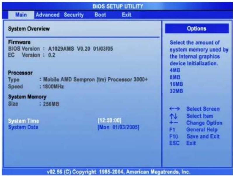
Once you enter the BIOS Setup Utility, the Main menu will appear on the screen. The Main menu displays the system information, including the basic configuration.
text_image
BIOS SETUP UTILITY Main Advanced Security Boot Exit System Overview Firmware BIOS Version : A1029AMS V0.20 01/03/05 EC Version : 0.2 Processor Type : Mobile AMD Sempron (tm) Processor 3000+ Speed : 1800MHz System Memory Size : 256MB System Time [12:59:00] System Date [Mon 01/03/2005] Options Select the amount of system memory used by the internal graphics device Initialization. 4MB 8MB 16MB 32MB ←→ Select Screen ↑↓ Select Item +- Change Option F1 General Help F10 Save and Exit ESC Exit v02.56 (C) Copyright 1985-2004, American Megatrends, Inc.Main menu
Show System Overview information about BIOS version, CPU features, Memory size and setting of System Time and Date.
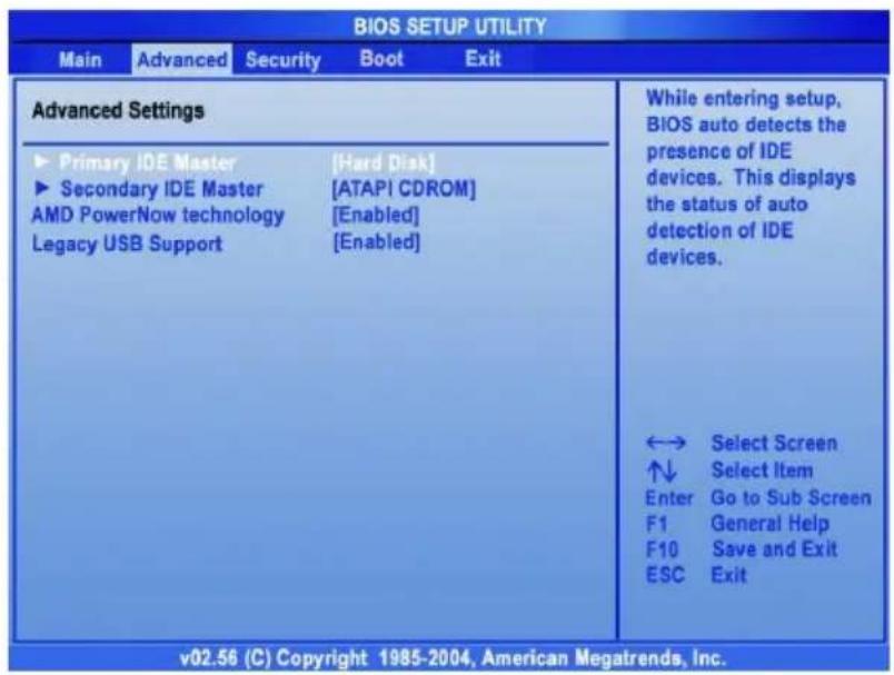
Advanced menu
Configure IDE and USB settings.
Security menu
Install or clear Supervisor's and User's Password settings.
Boot menu
Set up Boot Type and Boot Sequence.
Exit menu
Choose decided status before leaving the BIOS menu.
Main menu

text_image
BIOS SETUP UTILITY Main Advanced Security Boot Exit System Overview Firmware BIOS Version : A1029AMS V0.20 01/03/05 EC Version : 0.2 Processor Type : Mobile AMD Sempron (tm) Processor 3000+ Speed : 1800MHz System Memory Size : 256MB System Time [12:59:00] System Date [Mon 01/03/2005] Options Select the amount of system memory used by the Internal graphics device Initialization. 4MB 8MB 16MB 32MB ←→ Select Screen ↑↓ Select Item +- Change Option F1 General Help F10 Save and Exit ESC Exit v02.56 (C) Copyright 1985-2004, American Megatrends, Inc.System Overview
System Overview will show you BIOS version and other information about its build date and update notes. Following is CPU's information about its Type and Speed.
System Time
This item allows you to set the system time. The system clock will go on no matter you shut down the PC or get into sleep mode. The set format is [hour:minute:second].
System Date
This item allows you to set the system date. The date format is [day:month:date:year].
Day Day of the week, from Sun to Sat, which is determined by BIOS (read-only).
Month The month from 01 (January) to 12 (December).
Date The date from 01 to 31.
Year The year can be adjusted by users.
Advanced menu
text_image
BIOS SETUP UTILITY Main Advanced Security Boot Exit Advanced Settings ► Primary IDE Master ► Secondary IDE Master AMD PowerNow technology Legacy USB Support [Hard Disk] [ATAPI CDROM] [Enabled] [Enabled] While entering setup, BIOS auto detects the presence of IDE devices. This displays the status of auto detection of IDE devices. ←→ Select Screen ↑↓ Select Item Enter Go to Sub Screen F1 General Help F10 Save and Exit ESC Exit v02.56 (C) Copyright 1985-2004, American Megatrends, Inc.Advanced Settings
Primary and Secondary IDE Master
The two items display the types of the primary master/slave IDE devices installed in the Notebook. Press [Enter] to bring up a window showing the detailed information of the device, including the device name, vendor, LBA mode, PIO mode and more.
AMD PowerNow technology
This item allows you to enable or disable AMD PowerNow technology. When set to Enabled, the system always operates in a conserve power mode. If you want optimize the processor, set this item to Disabled, so that the processor's speed will vary depending on the use of your operating system and applications. Default setting is set
to Enabled.
Legacy USB Support
If you want to use USB device, like mouse, keyboard, portable disk, in DOS system or boot your system by USB device, you should enable this function by selecting Enabled.
Security menu

text_image
BIOS SETUP UTILITY Main Advanced Security Boot Exit Security Settings Supervisor Password : Not Installed User Password : Not Installed Change Supervisor Password Change User Password Install or Change the password. ←→ Select Screen ↑↓ Select Item Enter Change F1 General Help F10 Save and Exit ESC Exit v02.56 (C) Copyright 1985-2004, American Megatrends, Inc.Security Settings
Change Supervisor/User Password
When you select the function, a message box will appear on the screen as below:
Enter New Password
Type the password you want, up to six characters in length and press [Enter]. The password typed now will replace any previously set password from CMOS memory. You may also press [ESC] to abort the selection and not enter a password.
When the Supervisor Password is set, the new item User Access Level and Password Check will be added in the menu. You can make further settings of access right in the User Access Level item. Setting options: No Access, View Only, Limited and Full Access. The Password Check item is used to specify the type of BIOS password protection that is implemented. Settings are described below:
| Setup | The password prompt appears only when end users try to run Setup. |
| Always | A password prompt appears every time when the Notebook is powered on or when end users try to run Setup. |
To clear a set password, just press [Enter] when you are prompted to enter the password. A message box will show up confirming the password will be disabled. Once the password is disabled, the system will boot and you can enter Setup without entering any password.
info
About Supervisor Password and User Password
Supervisor Password allows the user to enter and change the settings of the setup menu; User Password only allows the user to enter the setup menu, but do not have the right to make changes.
Boot menu

text_image
BIOS SETUP UTILITY Main Advanced Security Boot Exit Boot Settings Quiet Boot [Enabled] 1nd Boot Device [CD/DVD:SM-QSI DVDR] 2nd Boot Device [HDD:PM-IC25N060ATM] 3nd Boot Device [Network:Realtek Bo] Disabled: Displays normal POST messages. Enabled: Displays OEM Logo instead of POST messages. ←→ Select Screen ↑↓ Select Item +- Change Option F1 General Help F10 Save and Exit ESC Exit v02.56 (C) Copyright 1985-2004, American Megatrends, Inc.Quiet Boot
This item enables you to show the vendor logo on the boot-up screen.
Settings options: Disabled and Enabled. The default setting is
Enabled.
1st, 2nd and 3rd Boot Device
The three items allow you to set the sequence of boot devices where
BIOS attempts to load the disk operating system.
Exit menu
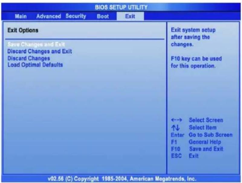
text_image
BIOS SETUP UTILITY Main Advanced Security Boot Exit Exit Options Save Changes and Exit Discard Changes and Exit Discard Changes Load Optimal Defaults Exit system setup after saving the changes. F10 key can be used for this operation. ←→ Select Screen ↑↓ Select Item Enter Go to Sub Screen F1 General Help F10 Save and Exit ESC Exit v02.56 (C) Copyright 1985-2004, American Megatrends, Inc.Save Changes and Exit
Save the changes you have made and exit the utility.
Discard Changes and Exit
Exit the utility without saving the changes you have made.
Discard Changes
Abandon your changes and reload the previous configuration before running the utility.
Load Optimal Defaults
Select this item to load the default settings for optimal system performance.