
VS-540-HDSDI - Security Camera MARSHALL - Free user manual and instructions
Find the device manual for free VS-540-HDSDI MARSHALL in PDF.


| Product Type | 2.0 Megapixel IP Security Camera with HD-SDI Output |
| Image Sensor | 1/3" CMOS |
| Optical Zoom | 10x (f=5.1–51 mm) |
| Digital Zoom | 12x |
| Day/Night | True Day & Night (ICR) |
| Video Compression | H.264, MJPEG |
| Max Resolution | 1920x1080 (Full HD) |
| Frame Rate | Up to 30 fps at all resolutions |
| Bit Rate | 32 kbps – 8 Mbps (CBR/VBR) |
| Video Output | HD-SDI (BNC), Composite (model dependent) |
| Audio | Full duplex, G.711/AAC, line level input/output |
| Network Interface | RJ-45 10/100 Ethernet with PoE (802.3af) |
| Supported Protocols | TCP/IP, UDP, Multicast, DHCP, SMTP, HTTP, SNMP, RTP, RTSP, DDNS |
| Serial Port | RS-485 (PTZ control, data pass-through) |
| Alarm I/O | 1 sensor input, 1 alarm output (relay) |
| Local Storage | SD card slot (supports up to 32 GB?) |
| Power Input | DC 12V or PoE (802.3af) |
| Dimensions (approx.) | Not specified in manual |
| Weight (approx.) | Not specified in manual |
| Operating Temperature | 0°C to 40°C (estimated) |
| Mounting | Desktop or ceiling mount (bracket not included) |
| Included Accessories | Quick Guide, CD with software and manual |
| Default IP | 192.168.10.100 |
Frequently Asked Questions - VS-540-HDSDI MARSHALL
User questions about VS-540-HDSDI MARSHALL
0 question about this device. Answer the ones you know or ask your own.
Ask a new question about this device
Download the instructions for your Security Camera in PDF format for free! Find your manual VS-540-HDSDI - MARSHALL and take your electronic device back in hand. On this page are published all the documents necessary for the use of your device. VS-540-HDSDI by MARSHALL.
USER MANUAL VS-540-HDSDI MARSHALL
2.0 Megapixel IP Camera with HDSDI output
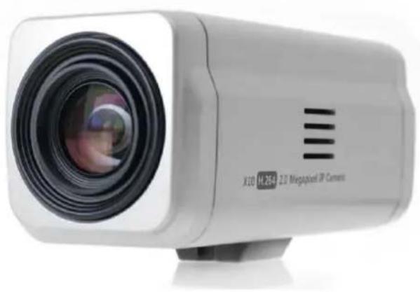
natural_image
Exterior view of a 3.10 X120 14.264 2.10 Megapixel IP Camera (no visible text or symbols on the device body)User Manual ver.1.0
Safety Precaution
We appreciate your purchasing VS-540-HDSDI. Before installing the product, please read the following with care.
Make sure to turn off the power before installing VS-540-HDSDI.
Do not install under the direct sunlight or in dusty areas.
Make sure to use the product within the temperature and humidity specified in the specification.
Do not operate the product in presence of vibrations or strong magnetic fields.
Do not put electrically conducting materials in the ventilation hole.
Do not open the top cover of the product. It may cause a failure or electric shock on the components.
To prevent from overheating, make sure to keep the distance at least 10cm from the ventilation hole.
Make sure proper voltage (220V/100V) before connecting the power.
Table of Content
- Introduction....4
About this manual....4
Features 4
Product and Accessories Part Names and Functions 6
Part Names and Functions....7
System Connections....8
- Installation.... 11
Connection 11
Check if it works 12
- System Operation 13
Remote Video Monitoring 13
Initialization of IP address....16
- Remote Configuration 17
Using Web Brower....17
System Configuration 18
Video Configuration....22
Audio Configuration....27
Network Configuration....28
Serial Configuration....33
Event Configuration....35
Preset Configuration.... 38
Record Configuration....39
User Configuration....48
Camera Configuration ....50
1. Introduction
About this manual
This User Manual provides information on operating and managing the premium network camera, VS-540-HDSDI. The Manual includes instructions of installation, operation and configuration of VS-540-HDSDI as well as how to make troubleshooting.
Features
VS-540-HDSDI is a 2.0M network-based camera with remote live monitoring, audio monitoring and control via an IP network such as LAN, ADSL/VDSL, and Wireless LAN.
Camera
• 1/3" CMOS Image Sensor
• X10 optical zoom, X12 digital zoom
• True Day & Night (ICR)
Video
• Highly efficient compression algorithm, H.264 & MJPEG support
• Resolutions: CIF (352x240) – Full HD (1920x1080)
• Wide range of transmission rates: 32kbps \~ 8Mbps
• Various transmission modes: CBR, VBR
- Motion detection
• Composite or HD-SDI or HDMI video output (Depending on Models)
Audio
- Multi-transmission mode: Simplex (VS-540-HDSDI → Client PC or Decoder, Client PC or Decoder → VS-540-HDSDI), Full Duplex
Network
• Fixed IP & Dynamic IP (DHCP) support
• 1:1, 1:N support
- Multicasting
- Various types of Protocol support : TCP/IP, UDP, Multicast, DHCP, SMTP, HTTP, SNMP, RTP, RTSP
Serial Data
• RS-485 support
• Data pass-through mode : Serial data communication between VS-540-HDSDI and Decoder
Sensor and Alarm
• Event Alarm notification.
• 1 alarm sensor Inputs and 1 alarm Output relays are available
User Interface
• Diagnose and upgrade through dedicated program called True Manager
• System configuration using Internet Explorer
High Reliability
• Reliable embedded system
Product and Accessories
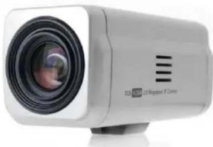
natural_image
White camera with lens and three-tiered ports, no visible text or symbols on bodyVS-540-HDSDI

Quick Guide

natural_image
Illustration of a CD or DVD disc with visible central hole and four surrounding discs (no text or symbols)SW and User Manual CD
Part Names and Functions
Rear
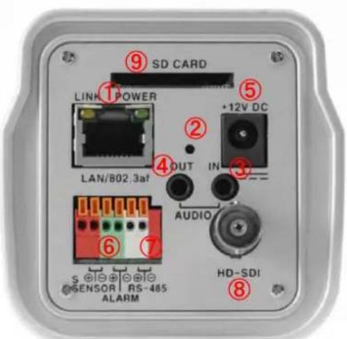
| Connector | Function |
| 1. Ethernet/802.3af | Ethernet port/802.3af LED :Booting and system check |
| 2. RESET Button | Initialization of network setting |
| 3. AUDIO IN | Audio input |
| 4. AUDIO OUT | Audio output |
| 5. POWER IN | DC 12V |
| 6. SENSOR/ALARM | Sensor input/ Alarm output |
| 7. RS-485 | RS-485 port |
| 8. VIDEO OUT | HD-SDI |
| 9. SD CARD | SD memory card slot |
System Connections
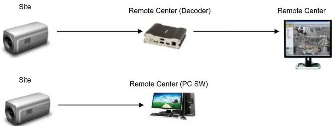
VS-540-HDSDI IP Cameras can be connected in either 1 to 1 connection where one VS-540-HDSDI is connected to one PC client or a decoder system or 1 to many connections where one VS-540-HDSDI can be connected to several PCs and decoder systems. (The VS-101 video server can work as a video decoder which takes the data from a video server or IP camera, decodes and outputs analog or digital video.)
Topology
Generally, VS-540-HDSDI and PC or a decoder is connected in 1-to-1 mode or 1-to many configuration.
- 1:1 Connection.
flowchart
graph LR
    A["Site"] --> B["Remote Center (Decoder)"]
    C["Site"] --> D["Remote Center (PC SW)"]
    B --> E["Remote Center"]
    D --> E
One VS-540-HDSDI is installed at a site where video images are transmitted. A PC or a decoder is installed at a central location to receive and view the video images on an analog monitor. Audio and serial data are transferred in either direction.
- 1:N Connection.
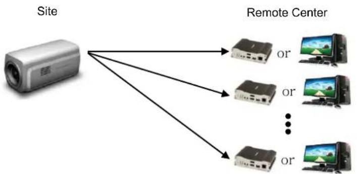
In this configuration, a site can be monitored from many remote central locations. Although up to 64 PCs or decoders can be connected to one VS-540-HDSDI, in the real network environment, network bandwidth can limit the maximum connections. Functionally, the central monitoring system (CMS) software provided can replace the decoder.
Multicast Mode
If the network supports multicasting, a large number of decoders can be used to receive video effectively from a VS-540-HDSDI using a single streaming of video and audio. However, multicast mode is possible only when the network environment supports multicast.
Relay
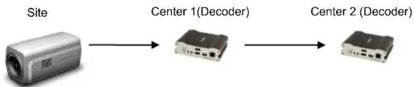
flowchart
graph LR
    A["Site"] --> B["Center 1 (Decoder)"]
    B --> C["Center 2 (Decoder)"]
Video and audio data can be retransmitted from one center to another center. This arrangement is useful when the network bandwidth to the site is limited and there are more than one center wanting to monitor the site.
CMS (Central Monitoring System)
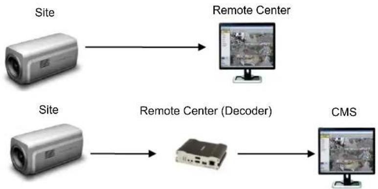
flowchart
graph LR
    A["Site"] --> B["Remote Center"]
    C["Site"] --> D["Remote Center (Decoder)"]
    D --> E["CMS"]
CMS (Central Monitoring System) is a Window-based remote monitoring program used to monitor or control video, audio, and events in real time from several IP cameras or video servers. Please refer to the CMS User Manual for more in detail.
2. Installation
Connection
Connecting Power
- Carefully check the voltage and current capacity of the rated power. The rated power is indicated on the back of the main unit.
- After confirming the power source, connect the power adaptor and connect the 12V DC connector to the system.
Connecting Network
- Plug the network cable to the Ethernet port (RJ-45 network port).
Connecting Video
-
To display video through the HD-SDI port, connect to a monitor using a BNC coaxial cable.
-
Set Enable Preview option "ON" on the Video tab of the web page. (Please refer to the Video Configuration part)
-
When using HD-SDI, video may contain errors if the correct type of BNC coaxial cable is not used.
- If the video transmission distance exceeds 100 meters, video data may lost due to a reduction in the video signal. In order to prevent this use of a repeater is recommended..
- When using HD-SDI, video can be only be viewed on a HD-SDI monitor
Connecting Audio
Audio is full-duplex. It is possible to set the mode as Tx-only, Rx-only or Tx-Rx.
- Connect the audio input and output ports to corresponding audio devices.
- The Audio signal required is line level. Audio equipment using an amp, mixer or other amplifier should be used.
Connecting Serial Port (RS-485 Communication)
- RS-485 of VS-540-HDSDI can be connected to external equipment such as a PT receiver etc. The PC client can send PT commands to the external equipment via the serial port.
When a decoder system instead of PC client is connected to VS-540-HDSDI, the serial port and that of the decoder system works in pass-through mode. That is, data from at one port is delivered to the other port and vice versa.
Connecting Sensor and Alarm
- Connect sensor and alarm devices to corresponding terminals accordingly
Check if it works
Once the power is supplied to the camera, it will start booting. The system will boot up to an operating mode after approximately 40-60 seconds. The green LED on the Ethernet port will flash indicating the system is ready.
The software provided in the CD called True Manager allows you to check the IP address and other network details of the camera. Please refer to the True Manager manual for instructions on how to find the IP address of the camera and change it if required.
3. System Operation
Remote Video Monitoring
There are two ways to monitor video when the center system and VS-540-HDSDI are connected. In order for a proper operation, an IP address must be set accordingly. Please refer to True Manager in Chapter 3 or Remote Setting in Chapter 4 for further details.
| Default ID : admin | Default Password : 1234 |
Video Monitoring using Internet Explorer
Live View
Sofin
Channe Hear
Open Internet Explorer and enter VS-540-HDSDI's IP address. The system will ask for confirmation to install Active-X control. Once authorized, the Internet Explorer will start to display video images from VS-540-HDSDI as shown below.
Default IP Address : http://192.168.10.100
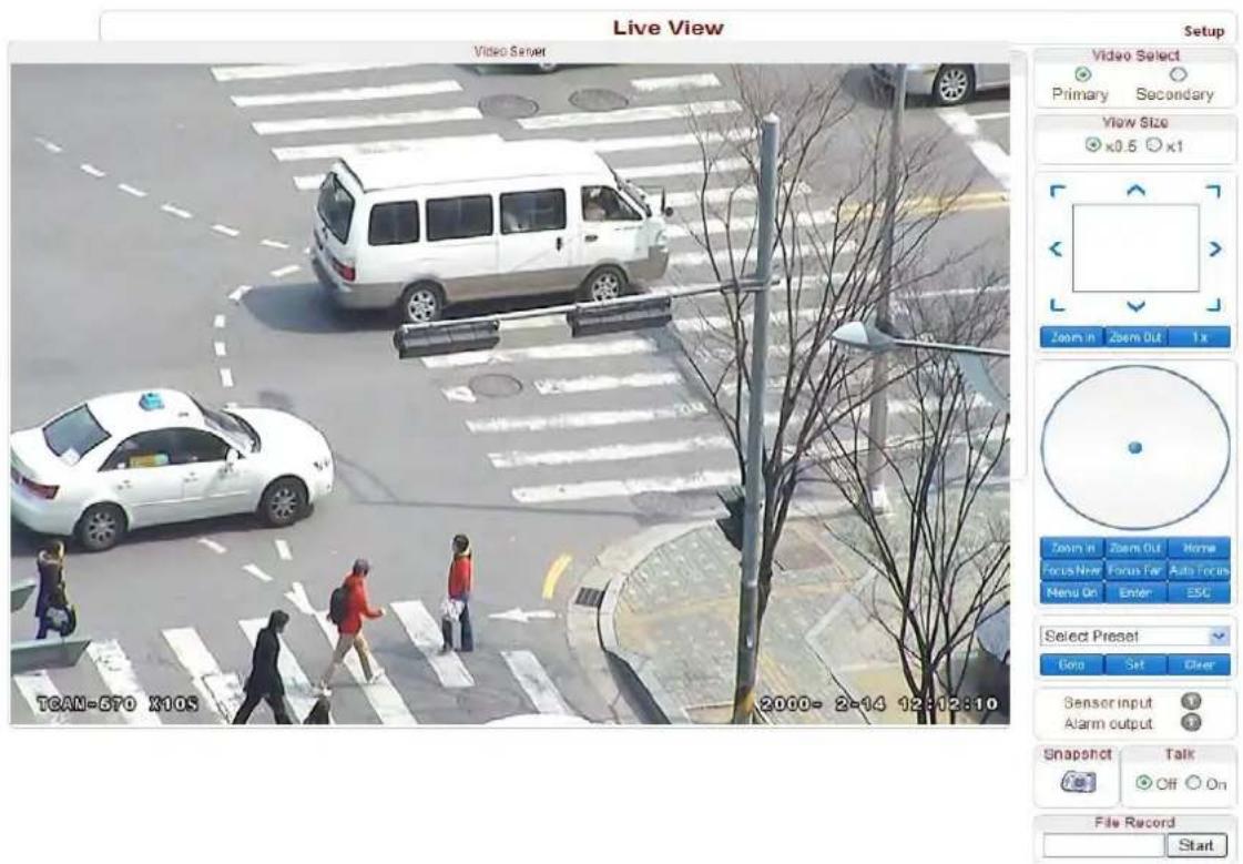
- Video Selection
Select the Video stream to be viewed: Primary or Secondary
VS-540-HDSDI is capable of dual streaming; primary streaming and secondary streaming.
Video will be displayed according to the resolution set in video configuration. If dual streaming "Use Dual Encode" Menu in Video page is not activated, secondary video is not available
- Screen Size
Adjust the Screen size
Screen size is initially adjusted according to the compression resolution. If you click x1/2 icon, the whole screen size will be reduced by half.
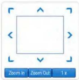
- Digital Zoom
Control the Digital zoom on the screen
The more the camera zooms in, the smaller the square of the control panel is. The Position of the image can be changed by moving position of the square. Max x5 Digital Zoom is available. If you press x1, the screen will return to the normal size.
● PTZ Control Panel (Optical Zoom)
Control PTZ and PTZ Control Panel is used for controlling external PTZ devices when the external PTZ devices are connected through serial port. Since x10 optical zoom lens is built in VS-540-HDSDI, it is possible to control zooming by using the Zoom in/out buttons of the PTZ control Panel.
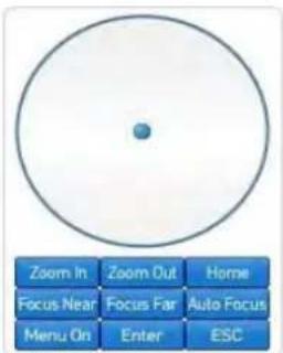
● Focus Near, Focus Far, Auto Focus
Adjusts the focus of the lens
- Menu On, Enter, ESC
Displays and control the OSD (On Screen Display) menu if OSD menu is supported.
NOTE: VS-540-HDSDI does not support OSD menu.
- Select Preset
Set preset position and move to the specific preset position.
- Go to: Moves to the selected preset entry if the preset entry is set.
- Set: Sets the current position to the selected preset entry.
- Clear: Deletes the selected preset entry.
- Sensor Input
Displays the status of the sensor in real time.
When the sensor of the VS-540-HDSDI is working, the sensor light turns red.
- Alarm Output
Operate the alarm device by pressing the number icon. A number icon indicates the status of the alarm device.
- Screen Capture
Captures video images and store them as BMP or JPEG files.
- Audio Transfer
Transfers audio from a PC displaying the current video image to the VS-540-HDSDI.
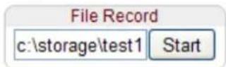
- File record
Recording to an AVI file from the Live view page is possible. AVI files are generated in the specified folder or file name on the PC where the web browser is running.
- Enter the drive and the folder name on the PC and enter the AVI file name to be used.
-
Press the "Start" button to begin recording.
-
Press the "Stop" button to end recording.
-
The AVI file named "File name_IP address_hh_mm_ss" will be generated in the specified folder.
Video Monitoring with Decoder System
Once VS-540-HDSDI's IP address is set in the remote IP address section of the decoder, the decoder system will connect to VS-540-HDSDI and start receiving the video images. Normally, a monitor connected to the decoder will display video images
Initialization of IP address
If a system IP address is lost, the system can be reset to the system default IP address using the Reset button on the back side of the system.
-
While the system is in operation, press the Reset button for more than 5 seconds.
-
The system will reboot automatically.
-
Once the system reboots, IP address will be set to the system default as below.
| • IP mode | Fixed IP | • IP address | 192.168.10.100 |
| • Subnet mask | 255.255.255.0 | • Gateway | 192.168.10.1 |
| • Base port | 2222 | • HTTP port | 80 |
4. Remote Configuration
Using Web Brower
Remote Setup is available by using the web browser. Enter the IP address of VS-540-HDSDI and the live view screen appears as below. Press the Setup button located in the upper right area of the monitoring screen to go to the server setup. For Remote Setup, the user must be authorized at higher than manager level.
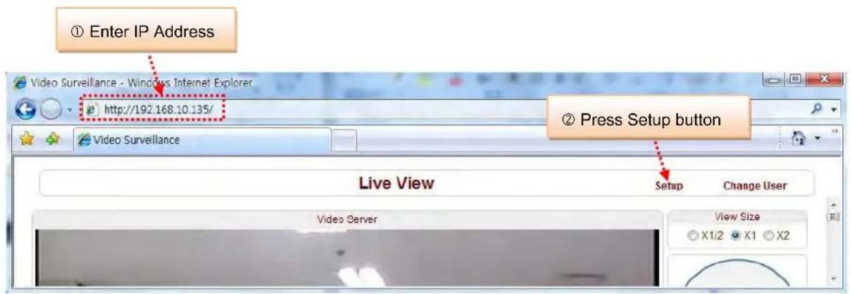
The configurations are grouped into 10 categories: System, Video, Audio, Network, Serial, Event, Preset, Record, User and Camera. Any configuration changes are not applied until the Apply button is pressed. Leaving the page without pressing Apply button, any changes in the page will be discarded.
System Configuration
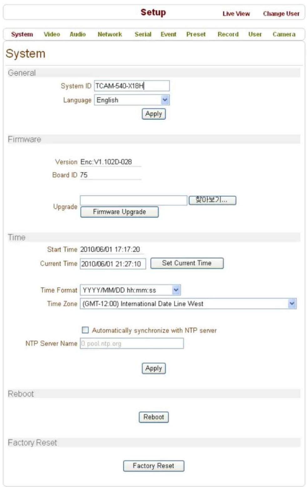
General
- System ID
Enter the System ID to be used as a camera title
The set System ID is displayed with video image on Web Browser. The System ID is also transferred to remote software, such as CMS, and displayed on it.
- Language
Select the language to be used for web-based configuration.
Firmware
- Firmware version
Displays the current firmware version.
- Board ID
Displays the Network board ID of VS-540-HDSDI recognized by system.
- Upgrade
Upgrade firmware
- Press the Browse button to select a firmware file from PC.
- Press the Firmware Upgrade button to start to upgrade.
- Messages showing the status of downloading / upgrading will be displayed.
- The camera will reboot automatically after completing the upgrade. Do not turn the camera off during the Upgrade process.
Firmware
Version Enc:V1.102D-001
Board ID 47
Now Downloading... Please wait...
Upgrade D:\cckskim\update_fw\hvsSys102C_
Browse.
Firmware Upgrade
Now, Upgrading... Please wait a minute.
Time
- Start Time
This is the date and time when the camera was booted.
- Current Time
Current date & time
Enter a new date and time and press Set Current Time button to update.
- Time Format
This allows you to change the time format. Selectable time formats are as follows:
- YYYY/MM/DD hh:mm:ss (Ex. 2010-4-11 18:18:42)
- DD/MM/YYYY hh:mm:ss (Ex.11-4-2010 18:18:42)
- MM/DD/YYYY hh:mm:ss (Ex. 4-11-2010 18:18:42)
- Time Zone
This allows you to select time zone where the camera is installed.
Depending on the time zone, Daylight Saving Time will work automatically
A time zone is a region of the earth that has uniform standard time, usually referred to as the local time. By convention, time zones compute their local time as an offset from UTC (Coordinated Universal Time). In casual use, GMT (Greenwich Mean Time) can be considered equivalent to UTC. Local time is UTC plus the current time zone offset for the considered location
● Automatically synchronize with NTP server
Checking this box will Synchronize the camera time with an NTP server using NTP (network time protocol). Enter the NTP server name of the NTP server to be used.
The Network Time Protocol (NTP) is a protocol for synchronizing the clocks of computer systems over packet-switched, variable-latency data networks. It is designed particularly to resist the effects of variable latency by using a jitter buffer.
Reboot
- Pressing this button will Reboot the camera.
Do not press the Reboot button unless required.
Factory Reset
- This changes the Current IP Address of VS-570-HDSDI to default IP Address, 192.168.10.100. The System log and user registrations are also cleared. All other setting values will remain. Note that the Password will not be changed by the Factory Reset for the security purpose. Please contactMarshall Electronics Technical Support if you forget your password.
Video Configuration
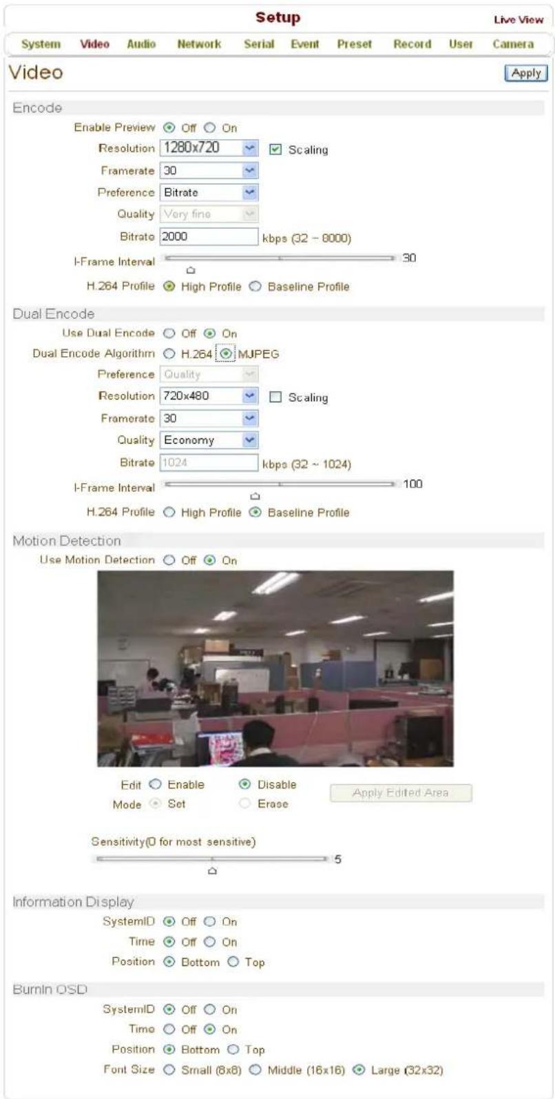
Encode
- Enable Preview
-
Select ON to display video on the monitor that is connected to the HD-SDI video port.
-
Select the appropriate Output format at the bottom of the Video page.
Note that when Enable Preview is ON, dual streaming is not available.
When the video is transmitted directly to the monitor through the BNC cable, the video signal bypasses the network and encoding.
- Resolution
This allows you to Select the video encoding resolution.
Eighteen resolutions from 352 x 240 to 1920 x 1080 are available.
The Scaling option is used when the encoding resolution is different from the input compression. Without the Scaling option, input video will be cropped according to the encoding resolution. On the other hand, if Scaling is selected, the input video will be adjusted according to the encoding resolution.
- Frame rate
Select the maximum number of frames per second for the video stream.
A frame rate of 1,2,3,4,5,6,8,10,15,20,25 and 30 can be selected. The actual frame rate of video can be less than the maximum frame rate set due to any network bandwidth limitation.
- Preference
Select encoding mode to control video quality: Quality or Bit rate.
If „Bit rate' is selected, the video encoding will be affected by the „Bit rate' value entered. Therefore, 'Bit rate' mode is CBR (Constant Bit rate) encoding.
If „Quality' is selected, the video encoding will be affected by the quality of image selected. Therefore, 'Quality' mode is VBR (Variable Bit Rate) encoding.
• Quality
Select the required Video quality. Eight levels of quality are available.
Quality mode (VBR encoding) adjusts the bit rate according to the image complexity, using higher bandwidth for increased activity in the video and lower bandwidth for decreased activity.
For active video content such as sports, or when network bandwidth is limited, It is recommended that CBR or Bit Rate encoding be used.
- Bit rate
Set the bit rate value between 32 \~ 8000kbps.
Bit rate mode (CBR encoding) allows you to set a fixed bit rate that consumes a predictable amount of bandwidth. If the network capacity is sufficient use of a fixed bit rate of 4096 kbps or higher will maintain a high quality picture regardless of content.
- I-Frame Interval
Set the I-frame Interval between 0 and 255.
There will be no I-frames if 0 is selected.
H.264 Profile
Select H.264 Profile: High Profile or Baseline Profile
The standard defines various sets of capabilities, which are referred to as profiles, targeting specific classes of applications.
- High Profile (HiP)
The primary profile for broadcast and disc storage applications, particularly for high-definition television applications (for example, this is the profile adopted by the Blu-ray Disc storage format and the DVB HDTV broadcast service).
- Baseline Profile (BP)
Primarily for low-cost applications that require additional data loss robustness, this profile is used in some videoconferencing and mobile applications. This profile includes all features that are supported in the Constrained Baseline Profile, plus three additional features that can be used for loss robustness (or for other purposes such as low-delay multi-point video stream compositing).
Dual Encode
- Use Dual Encode
- Select the Off button on the Enable Preview to enable to use Dual Encode
- Select the ON to enable to use Dual Encoding
The secondary video can be viewed in the Live View window by selecting Secondary on Video selection
- Dual Compression Algorithm
Select H.264 or MJPEG for the secondary streaming.
Maximum resolution is 1280 x 720 and 9 steps of resolution are available. If MJPEG is selected, only "Quality" mode is supported
Motion Detection
- Use Motion Detection
Select ON to use the Motion Detection function.
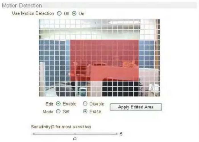
● Motion Detection Area Editing
Configure regions for motion detection. Regions of arbitrary shapes can be configured using the following steps:
① Select the Enable button ajacent to the Edit heading.
② Select editing Mode. Set is for including cells to motion detection region and Erase is for excluding.
③ Select cells using the right mouse button. Multiple cells can be selected conveniently by pressing and dragging.
④ Press Apply Edited Area to save the editing
- Sensitivity
Sensitivity selects the amount of movement required to trigger (detect) a motion event.
The value determines the sensitivity of the motion detection within a block: the lower the number the more sensitive to movement. Select from 0 to 10.
● Information Display
System ID and/or server time can be displayed over the video window in Internet Explorer. Each item can be turned on or off separately, and position also can be configured. This information is displayed after the video is decompressed
- Burn-in OSD
Insert system ID and date/time in the compressed video. System ID and time respectively can be turned on or off in the video, the Position and Font size is selectable.
Note: Since time information is inserted when the video is compressed, the changing characters of the time display is detected as motion. Therefore, even though there is no motion, an event will be triggered. In order to prevent this, exclude the area displaying time using Motion detection area editing.
Output Format
The Output Format menu appears only when Enable Preview is on
Output Format
Output Format
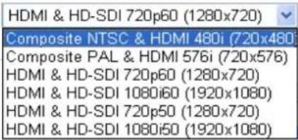
Select the output format for the monitor preview according to the video output and monitor specification.
Audio Configuration
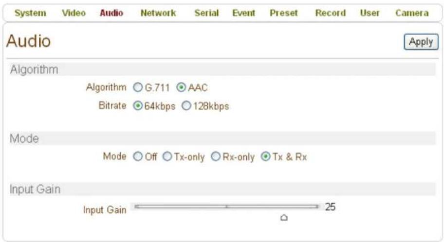
Algorithm
- Algorithm
Select the audio algorithm: G.711 or AAC
- Bit rate
Select the Bitrate to be 64kbps or 128kbps when AAC is selected.
The sampling rate is fixed to 32KHz when G.711 is selected.
Note that when VS-540-HDSDI is connected to a decoder, the decoder's audio algorithm MUST be set identically to transmit audio and video properly.
Mode
- Select the audio Transmit / Receive mode:
| Mode | Action |
| Off | No operation |
| Tx-Only | Transmit only |
| Rx-Only | Receive only |
| Tx & Rx | Transmit and Receive |
Input Gain
- Set the audio input gain from 0 to 31.
Network Configuration
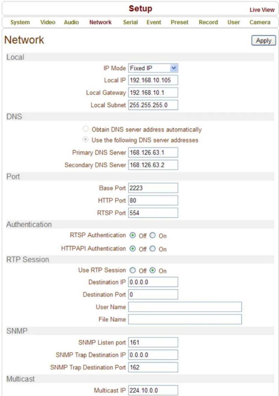
DDNS
DDNS Server ○ None ● TrueDNS ○ DynDNS
□ Check IP Disable
ID
Password
Domain Name
Bitrate Control
Flow Control Mode ◦ Frame Drop Mode ◦ Suppression Mode
Address Information
Current IP 192.168.10.105
Current Domain demo3.truecam.net
MAC Address 00:1C:63:AA:01:65
Connecting
Local
- IP mode
Select the IP mode: Fixed IP or DHCP (Dynamic Host Configuration Protocol)
Depending on the mode selected, configuration items will appear as follows:
| IP Mode | Selection | Description |
| Fixed IP | Local IP | Fixed IP address |
| Local Gateway | Gateway IP address | |
| Local Subnet | Subnet mask | |
| DHCP | N/A |
Please request IP address information from your ISP provider or network manager.
DNS
- Obtain DNS server address automatically
The DNS server address automatically acquired when IP mode is DHCP.
- Use the following DNS server addresses
Manually enter the DNS server IP address.
- Primary DNS server
- Secondary DNS server
Domain Name System (DNS) is a database system that translates a computer's fully qualified domain name into an IP address. Networked computers use IP addresses to locate and connect to each other, but IP addresses can be difficult for people to remember. For example, on the web, it's much easier to remember the domain name www.amazon.com than it is to remember its corresponding IP address (207.171.166.48). Each organization that maintains a computer network will have at least one server handling DNS queries. That server, called a name server, will hold a list of all the IP addresses within its network, plus a cache of IP addresses for recently accessed computers outside the network.
Port
- Base Port
Enter the Base Port number.
The Network base port is used for communication between systems. In order for VS-540-HDSDI and remote systems (decoder or CMS, NVR software) to be connected, the port numbers must be identically set.
- HTTP Port
Enter the HTTP port used for web-based connections.
- RTSP Port
Enter the RTSP port used for RTSP-based connection. The default RTSP port is 554.
RTSP (Real Time Streaming Protocol) is a standard for connected client(s) to control streaming data over the World Wide Web.
Authentication
- RTSP Authentication
If the RTSP Authentication set to ON, the user must enter correct User ID and Password when any RTSP client is connected.
- HTTP API Authentication
When HTTP API authentication set to ON, HTTP Authentication is asked for all clients which use HTTP API.
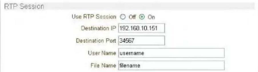
RTP Session
- RTP (Real-Time Transport Protocol) is an Internet protocol used for transmitting single real-time multimedia data such as audio and video to a select group of connected clients. Normally RTSP uses RTP to format packets of multimedia content. RTP Session menu is used when the RTP only streaming without RTSP connection. RTP stream will be transmitted to the destination set. The SDP (Session Description Protocol) file can be found in the server, and a client can retrieve it using http connection.
Related settings are as following.
- Destination IP : Set the IP Address for your destination system which will receive RTP stream.
- Destination Port : Set the Port for your destination system which will receive RTP stream.
- User Name: Enter the User name that will be used as session name in the SDP file.
- File Name: Enter the file name that will be used as the name of the SDP file. It can then be accessed through http://ServerAddress/filename.
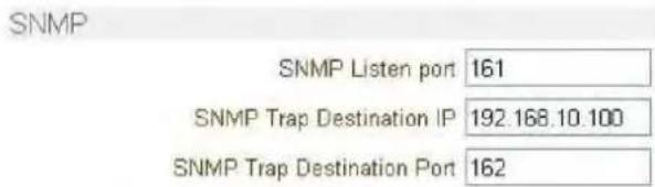
SNMP
- The VS-540-HDSDI can be used as an SNMP agent. It is compatible to both SNMPv1 and SNMPvec. Settings for using SNMP (Simple Network Management Protocol) are as follow:
- SNMP Listen Port: This port is used for connecting external devices when the system operates as an SNMP client. SNMP is not used when setting a 0 value.
- SNMP Trap Destination IP: Set the SNMP Trap Destination IP.
- SNMP Trap Destination Port: Set the SNMP Trap Destination Port. SNMP is not used by setting 0 value.
Simple Network Management Protocol (SNMP) is used by network management systems to communicate with network elements. SNMP lets TCP/IP-based network management clients use a TCP/IP-based internetwork to exchange information about the configuration and status of nodes. SNMP can also generate trap messages used to report significant TCP/IP events asynchronously to interested clients. For example, a router could send a message if one of its redundant power supplies fails or a printer could send an SNMP trap when it is out of paper.
Multicast
- Multicast IP
The multicast IP address selection range is between 224.0.1.0 and 238.255.255.255. The selection can be used only when media protocol is set to Multicast. The Multicast menu is used for the Multicast connection request from a decoder or CMS / NVR software to transmit Multicast stream to the decoder or CMS / NVR software. The multicast address must be the same for the system to be connected using multicast protocol.
DDNS
Select the DDNS (Dynamic DNS) server to use. One of the two servers can be selected.
- True DNS: TrueDNS service is used in this mode. Systems can be registered on the website for TrueDNS service: http://ns1.truecam.net. The System will get a domain name of xxx.truecam.net style. Please, refer to the user guide document for True DNS service.
- DynDNS: DynDNS service is used in this mode. Refer www.dyndns.org for details. ID, Password and Domain name are needed when DynDNS is set.
Dynamic DNS is a method, protocol, or network service that provides the capability for a networked device, such as a router or computer system using the Internet Protocol Suite, to notify a domain name server to change, in real time (ad-hoc) the active DNS configuration of its configured hostnames, addresses or other information stored in DNS.
- Check IP Disable: If "Check IP Disable" is selected, IP Server will skip to check its own IP. In Fixed IP mode, the set IP will be registered on DDNS server. In DHCP mode, the allotted IP will be registered on DDNS server. Normally Check IP Disable can be unchecked.
Bitrate control
- When there is more than one client connected to the VS-570-HDSI, due to bandwidth difference among the clients some of them may not have enough bandwidth to receive the encoded stream completely. In this case, it is possible to select the way to stream video to clients as follows:
- Frame Drop Mode: Encoding will be adjusted to the client with the highest bandwidth. Clients with limited bandwidth may not receive all the frames.
- Suppression Mode: Bit rate and frame rate are adjusted most efficiently for all clients. In this case, all clients can be affected by the averaged bit rate and frame rate.
Address Info
● The following network information is displayed as Read only:
- IP Address: The Camera's own IP address. This information is useful when the camera's IP mode is set to DHCP.
- Domain Name: If the camera is registered at a DDNS server, the registered domain name is displayed.
- MAC Address: Displays the MAC address of the camera. If the camera is registered at a DDNS server, the MAC address is used in DDNS registration.
- Connecting: Client IP Addresses that are currently connected to the system are listed. (1) Indicates Primary Streaming and (0) Indicates Secondary streaming.
Serial Configuration
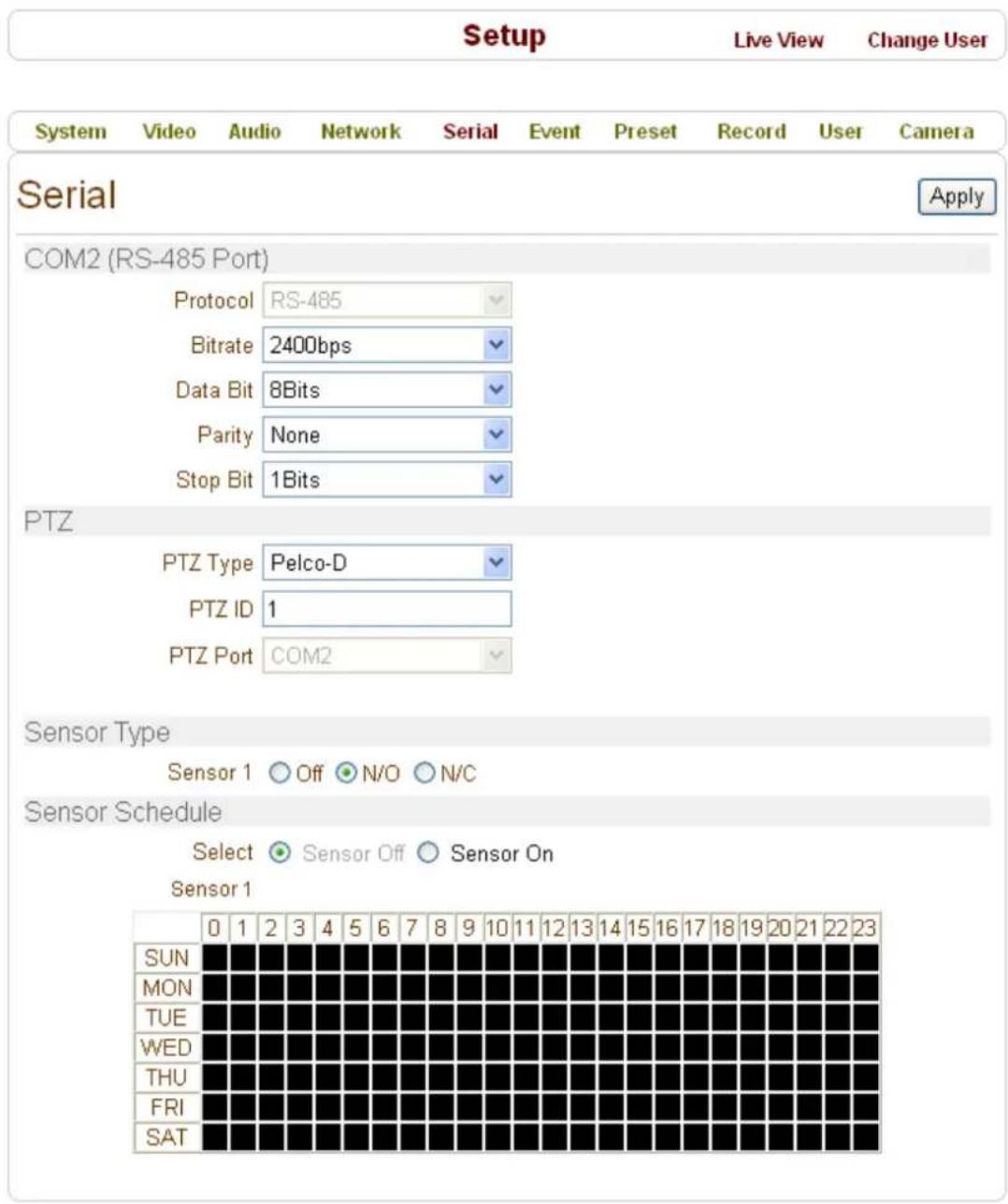
Serial Port Configuration
- Serial Port Information
The RS-485 in the VS-540-HDSDI support one RS-485 serial port.
The serial ports can be configured as follows.
Each of the serial ports configurations must be same as the connecting device.
| Mode | Selection |
| Bitrate | 2400, 4800, 9600, 19200, 38400, 57600, 115200 bps |
| Data Bits | 5, 6, 7, 8 bits |
| Parity | NONE, EVEN, ODD bit |
| Stop Bit | 1, 2 bit |
PTZ
● PTZ Type: Select the type of PTZ camera or receiver.
- PTZ ID: Since it is possible to control multiple PTZ cameras or receivers over a single control line, each camera or receiver must be assigned a unique ID. Enter the PTZ ID of a camera or receiver for control. The ID value range can be between 0 and 255.
● PTZ Port: Select the serial port used for PTZ camera control.
Sensor Type
● The sensor port can be configured to the following:
| Function | Operation |
| OFF | Not used |
| NO (Normally Open) | The port is normally open and activated when closed. |
| NC (Normally Closed) | The port is normally closed and activated when opened. |
The function of the sensor port is set based on the type of the sensor connected.
Sensor Schedule
- If you select sensor ON, Each sensor port can be enabled or disabled by day of the week and hour units. Sensor is disabled during the grey-colored duration.
Event Configuration
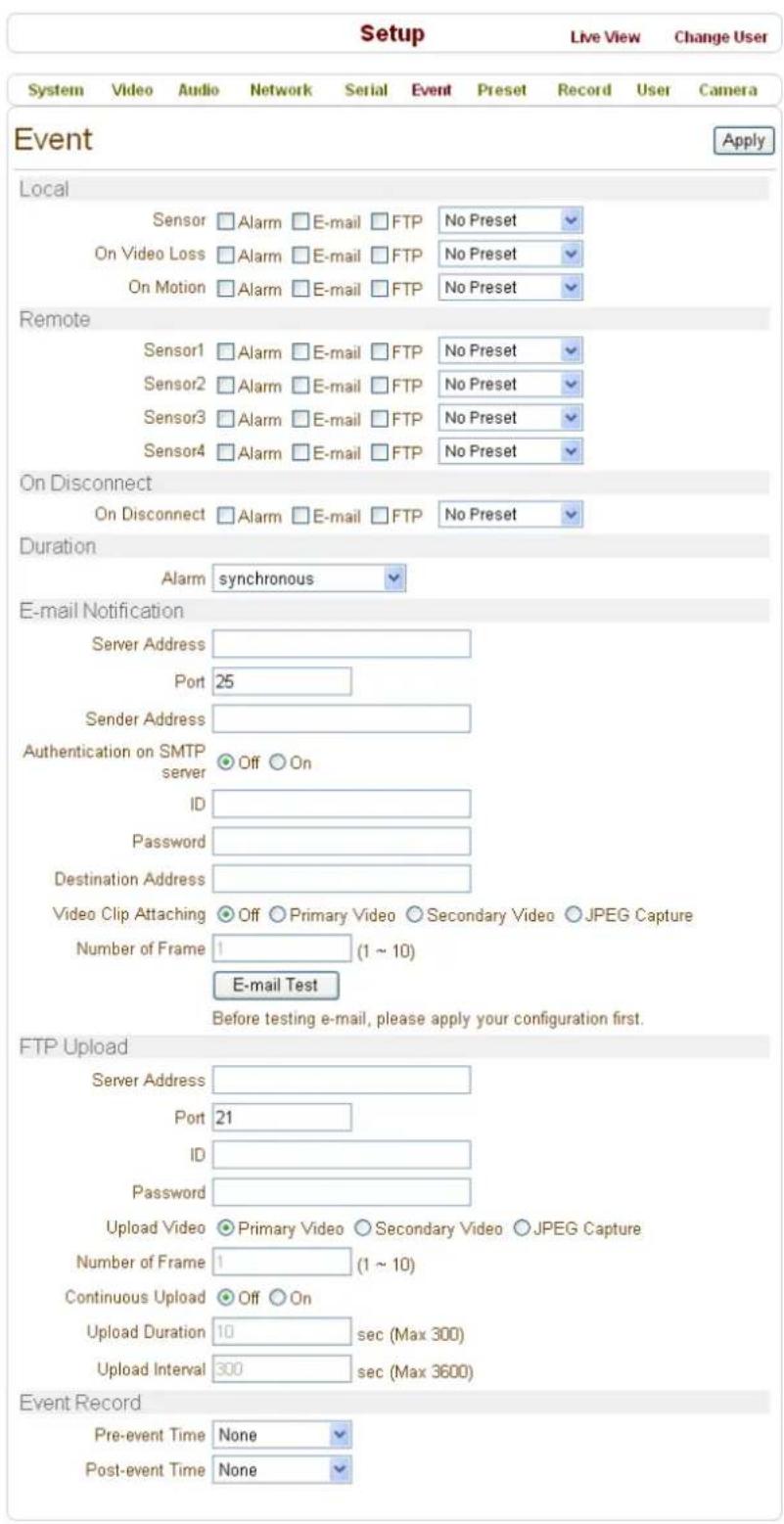
When a decoder instead of a PC client is connected to a VS-540-HDSDI, one system becomes a Local system and the other a Remote system. Generally a system which is being used by the user is called as Local system. Then, actions for events can be configured for events from the remote system as well as for local system. For example, it is possible to turn on an alarm device in local (center) decoder system when a sensor device in remote (site) IP camera is triggered. Local section configures the actions for events from local (self) system, and configuration activates local devices. Remote sections configure the actions for events from the remote (peer) system.
The following table lists the possible actions for events:
| Action | Description |
| Alarm out | Triggers alarm (relay) port. |
| Sends E-mail to the specified address, an AVI file can be attached. | |
| FTP | Upload AVI file to a specified FTP server. |
| Preset | Move to the Preset position. |
Local & Remote Event Configuration
- Sensor1 / Sensor2/ Sensor3 / Sensor4.
Configures the actions when the sensor is activated. Multiple actions can be set for a single event.
- On Video Loss
Configures the actions when video input signal is lost. Multiple actions can be set for a single event.
- On Motion
Configures the actions when motion is detected. Multiple actions can be set for a single event.
- On Disconnect
Configures the actions when the link (connection) with peer system is disconnected. Multiple actions can be set for a single event.
Alarm and Beep activation duration
- Set the duration of alarm or beep activation in case of an event. If it is set to continuous, it will be in an active state until an operator resets it manually.
E-mail Notification
- Specifies the E-mail configuration when E-mail is selected as an event action.
- Server Address: Enter an address of mail (SMTP) server - Port: Specify a port for SMTP operation. Port 25 is the default port in SMTP operation. If a different port is configured in the SMTP server, this port needs to be changed accordingly.
- Sender Address: Enter an account registered in the SMTP server.
- ID & password: When the server requires authentication, ID and Password of an E-mail account need to be entered.
- Destination address: Enter the Destination address. More than one address can be entered by delimiting comma (,) or semi-colon (;). The Destination address can be up to 63 characters long.
- Video Clip Attaching: A Video clip stored at the moment of an event can be attached as an AVI or JPEG file format. If using dual Encoding, Primary video or Secondary video (H.264 only) can be selected.
FTP Upload
- Specify the FTP configuration to upload event information when FTP is selected as an event action.
- Server Address: Enter the address of an FTP server to receive video files. - Port: Specify a port for FTP operation Port 21 is the default port in FTP operation. If a different port is configured in the FTP server, this port needs to be changed accordingly.
- ID & password: Enter ID and Password for accessing the FTP server.
- Upload video: Primary video and Secondary video (H.264 only), JPEG can be selected as an upload method.
- Number of Frame: Enter a frame number of JPEG Capture (from 1 to 10).
- Continuous upload: Continuous upload "on" allows the video image to be transmitted regularly, regardless of the occurrence of events.
- Upload duration: Specify recording duration of a video clip to be transmitted. (Max 300 sec).
- Upload interval: Specify transmission interval. (Max 3600 sec).
Recording duration is not included in the transmission interval. For example, if the Upload interval is 60 seconds and the Upload duration is 20 seconds, a Video clip of 20 seconds is transmitted every 80 seconds.
Event Record
- Specify duration of recorded video generated by events to send through E-mail or upload through FTP.
- Pre-event Time: Specify the duration of the recording before an event happens.
- Post-event Time: Specify the the duration after the event is cleared.
Max duration is 30 seconds.
Preset Configuration
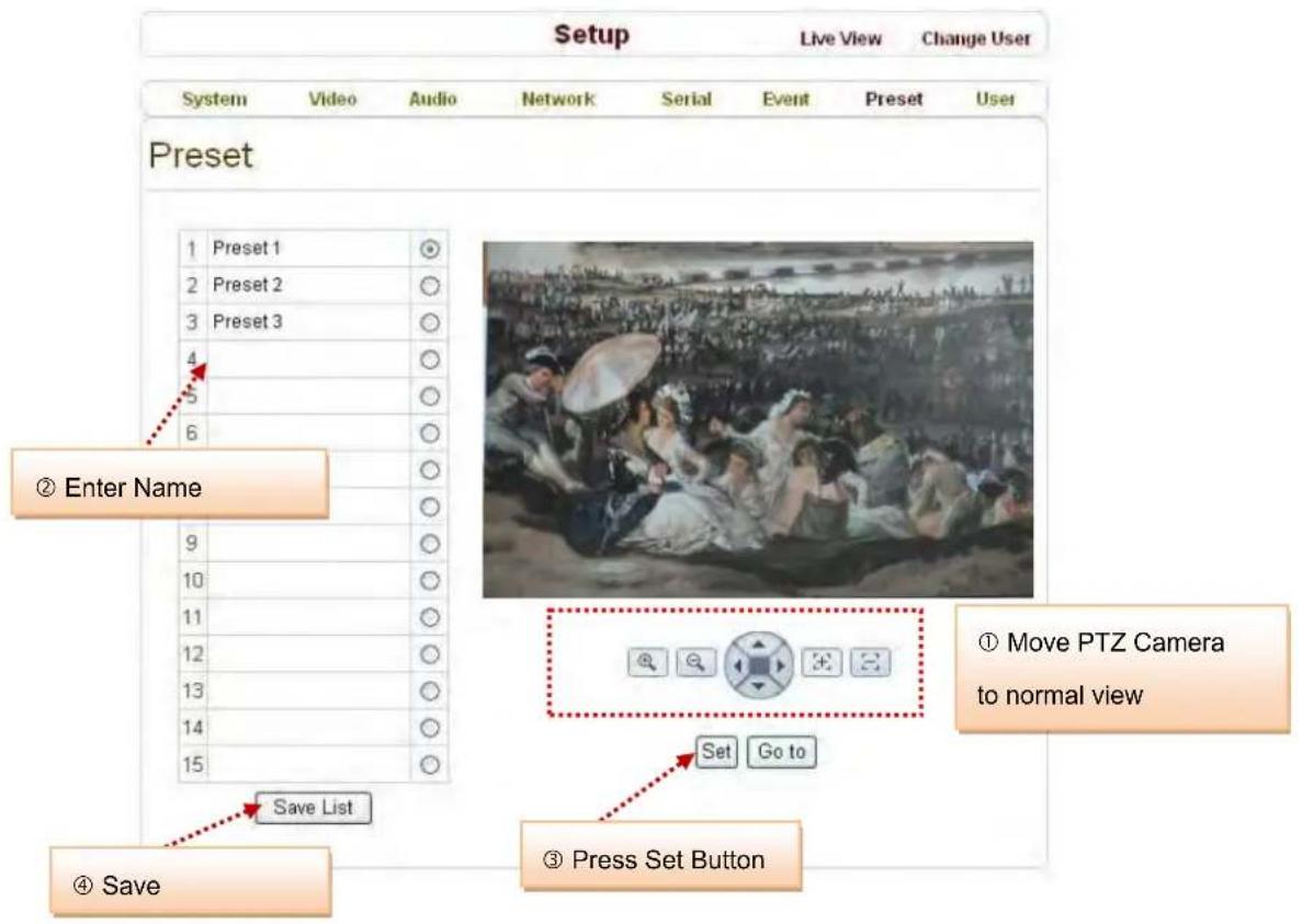
This function is only available when a PTZ receiver is used with the camera
Configure up to 15 preset positions. Preset function is not available on some PTZ receivers. Make sure to check if a PTZ receiver supports presets.
Preset Configuration
- Set the PTZ Presets by following the next steps
① Move the camera to a desired view using the PTZ control buttons.
② Enter Preset name.
③ Press Set button.
④ Once all the presets are set, press Save List button.
- Move to Preset Position
Select a preset from the Preset and press Go To button, the camera will move to the selected preset position.
Record Configuration
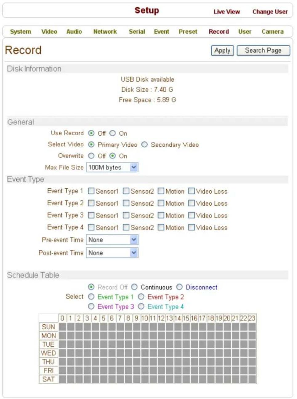
Recording to SD Card
- A/V data can be recorded to an internal SD card. An SD card with at least 1GB of storage space is recommended. Either EXT3 or FAT32 file system can be used. A Linux PC can read any of these file systems. On the other hand, a Windows PC can only read a FAT32 File
*A video bit rate of 4Mbps or less is recommended when you record and monitor video at the same time as higher bit rates may cause frame loss.
Disk information and recording setup
- Be sure to restart the system after inserting an SD Card. During booting, the system reads the status of the disk and initializes it. Once the initialization of a disk is finished, the status of the disk is shown on the Record page of web-based setup.
- Disk Information
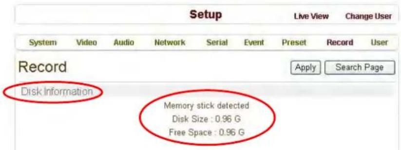
● The status of a disk can be checked from the Disk Manage menu of True Manager as well.
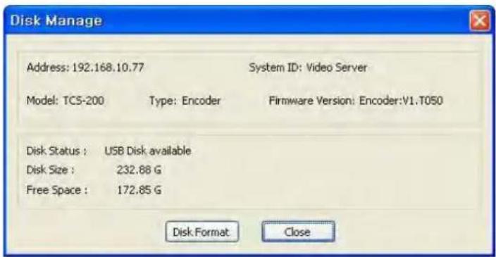
- Refer to the chart for checking the status of disk.
| Disk status | Description |
| Disk error detected | Error |
| No disk | Disk is not connected to the system. |
| Searching Disk information | Checking the status of disk. Refresh the page and wait until the status is changed. |
| Mounting and Recovering Disk... | Performing recovery process when disk damage is found. It takes from seconds to minutes for recovering. |
| Disk format needed | Disk is attached, but the type of the file system is unknown or damaged. |
| Unknown disk type detected | |
| USB or SD Disk available - (format is recommended) | Disk is available, but formatting is recommended. |
| USB or SD Disk available Avai able to be used for recording. | |
| Disk formatting – Start | Disk is being formatted. System should not be turned off during formatting. |
| Disk formatting – Progressing...... | |
| Disk formatting – Writing inode tables 63/619 | |
| Disk formatting – Creating journal...... | |
| Disk formatting – Writing Superblocks...... | |
| Disk format done, Please wait for reboot. | |
| Disk removed or in abnormal state | The Disk was detached during operation or there is damage to the file system. If this happens while the disk is connected, it is recommended to format the disk. |
General
- Use record - On: Recording function will be used when "On" is selected.
- Off: Recording function will not be used when "Off" is selected
- Select Video: Select video streaming between primary video and secondary video.
- Overwrite: Configure the overwrite option when the disk is full. If Overwrite is set Off, recording will stop automatically when there is less than 100MB of free space remaining on the disk. If Overwrite is set to On, recording will continue by deleting the oldest data on the disk first, maintaining free space of 300MB for normal operation.
- Max File Size: The Max File Size option sets the size of AVI files. If a small file size is set, files of smaller size will be generated but the numbers of files will be increased. If recording time is more than 10 minutes, a new file will be created even though the file size is set to be smaller than set max file size.
Event Type
- Three recording modes are supported in VS-540-HDSDI: Full-time, Event, and Disconnect. Event recording allows event types to be selected from mong several events. Event types are sed for configuring the schedule table. Up to 4 event types can be configured and each event type can be a combination of sensor, video loss and motion event.
● Pre-event Time: Specify the duration of the recording before an event happens.
● Post-event Time: Specify the the duration after the event is cleared.
Schedule Table
- The recording mode is determined by selecting Off, Continuous or Disconnect. When to Record is configured by the checking boxes in Schedule Table for the appropriate day of the week and time of day.
- Each recording mode configures the recording operation as follows:
- Record off : No recording
- Continuous : Records continuously
- Disconnect: Data is recorded when the system loses the connection to its client (Decoder, CMS/NVR) etc. NOTE: If one of multiple client systems is disconnected, this will not trigger record.
- Event Type: Records when an event configured in Event Type setting occurs.
Checking status of recording
● Recording status can be shown on the main view page.
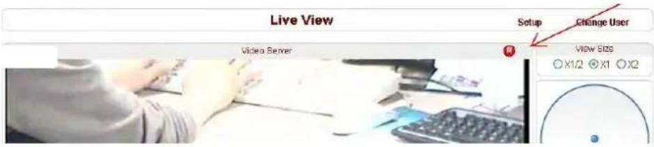
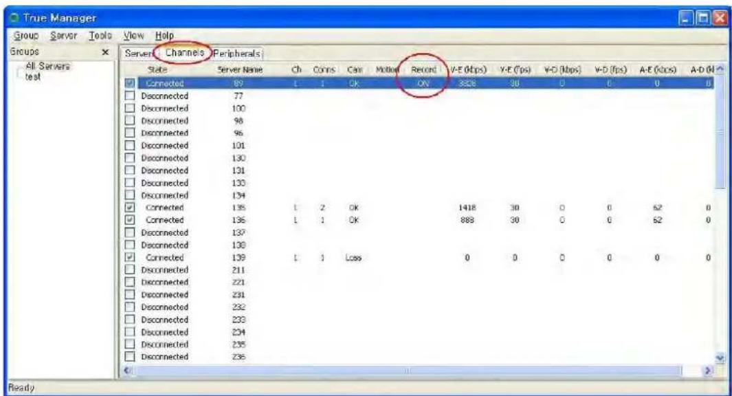
- Recording status can be also shown in True Manager. When data is being recorded, Record column displays ON sign.
Search and Playback
- Recorded File
- Recorded video and audio data can be saved as AVI format in the disk. In general, one AVI file is created for each event in case of Event-Based Recording. However, it is possible that data recorded by a series of events happening continuously can be merged to a single AVI file depending on pre/post event time setting. The file size is limited to 10 \~ 200MB or 10 minutes.
- In case of Continuous Recording, AVI files are created in series and the size of each is limited to 10 \~ 200MB or 10 minutes.
- Search
- A file currently being recorded will not appear until after it is completed. For Continuous recording, a file will appear after about 10 minutes from the start of the recording. The actual time depends on the Max file size which will determine the length of each segment.
- Press the Search Page button on the Record setup page. Dates with recording data will be shown as follows:

- First, choose the date for your search and a list of AVI files will be shown.
- The file name shows the date and time: "Date Begin Time End Time.avi".
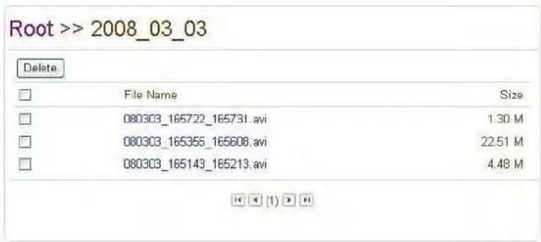
- Press Root to move back to the page with date list.
- Playback
- Selecting an AVI file will show a dialog for opening or saving the file.
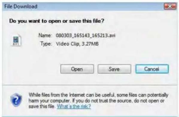
- Press the Save button to store the file on the PC. The AVI file can be played with Windows Media Player.
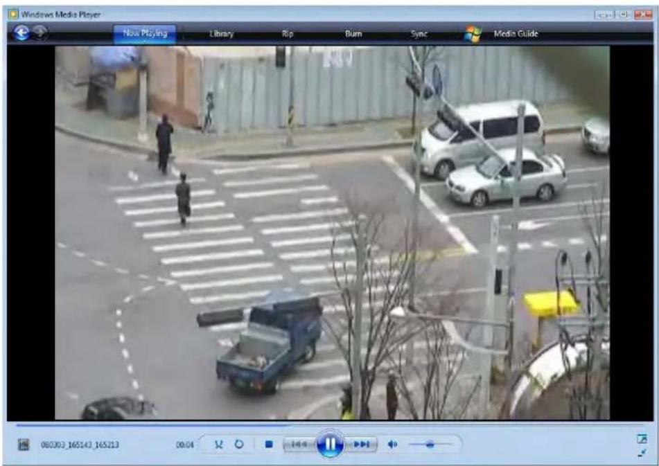
- If you press the Open button in the dialog box, the file will be downloaded and played automatically with Media Player.
- While downloading a file all other web connections are disabled. It is also not allowed to download two AVI files at the same time.
Delete
- If you want to delete recorded files, select the files by checking the box in front of each file and press the Delete button.
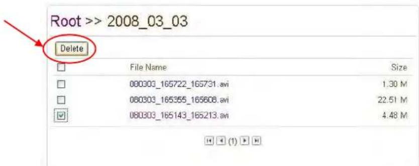
- It is possible to delete multiple files at once.
Format disk
- True Manager is used to format the SD card which is inserted in the system.
- After connecting True Manager to a system, choose Disk Manage on the Tools menu.
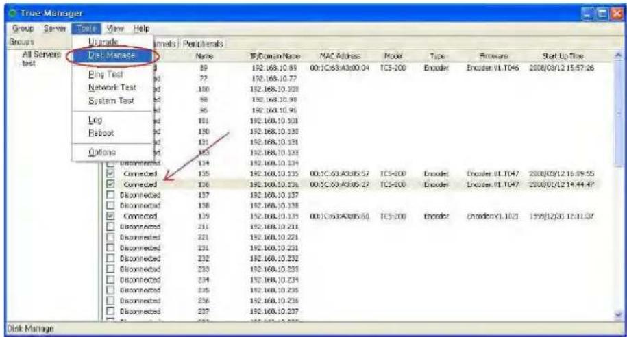
- Check the status of the disk in the dialog box and press Disk Format to format the disk.
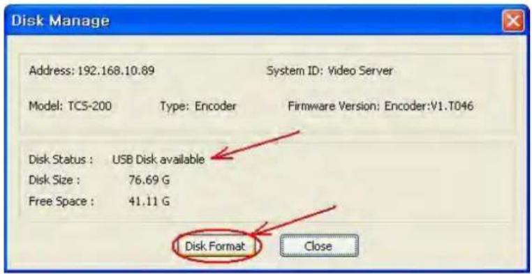
- While formatting a disk, the progress will update in the Disk Status field. The system may be rebooted depending on the situation. Once the USB Disk available is displayed, it means that formatting has completed successfully.
- Once formatting is started, it is not allowed to cancel. Even if you close the Disk Manage dialog, box, formatting will continue.
Trouble Shooting
- There may be damage in the file system if you turn off the power of VS-540-HDSDI or remove the SD memory card while any data is being written.
- For FAT32, recording in not possible if the file system is damaged. If this happens, the SD card should be reformatted on the PC.
- For EXT3, if the damage to the file is not serious, it can be automatically recovered. The recovery is executed at the initialization of the system.
User Configuration
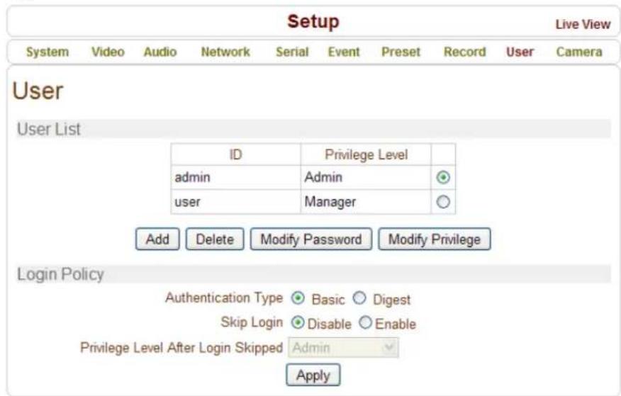
User List
- Users can be registered and the privilege level of a user can be specified. User configuration is allowed only by the Admin user. A Max of 16 users can be registered and each user can have one of four privileges:
| Privilege | Allowed Operations | Remarks |
| Admin | All operations | User ID = admin |
| Manager | All operations except for user configuration | |
| User | Live viewing and PTZ control | |
| Guest | Live viewing only |
Add User
- Press the Add button. The following window will appear:
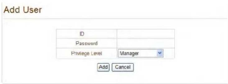
- Enter the User ID and password (up to 15 characters) and select Privilege Level
Delete User
- Select the User to be deleted and press the Delete button.
Change Password
- Press Modify password button. The following window will appear:
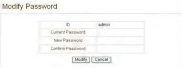
- Enter the current password and then set a new password.
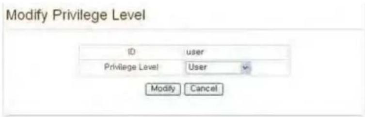
Modify Privilege Level
- Press the Modify Privilege button to change the User level. It is not allowed to change the privilege level of Admin user.
Login Policy
- Authentication Type
For user login, the following access algorithms can be selected: Basic or Digest
HTTP authentication based on RFC 2617 (HTTP Authentication: Basic and Digest Access Authentication) is supported.
- Skip Login
Skip Login provides for convenient access to the server when authentication is not required. When Skip Login is set to Enable, the login step is skipped. The privilege level after login skip is determined by the setting of Privilege Level After Login Skipped.
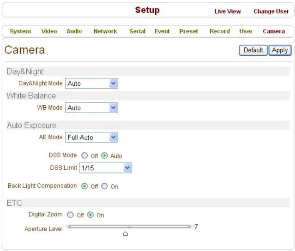
Camera Configuration
Day & Night
-
The camera delivers color images during the day. As light diminishes below a certain level, the camera can automatically switch to night mode (Black & White mode) to maintain good image quality.
● Day & Night function can be selectable according to environment. -
Auto : Automatically switches to Day (Color) or Night (B&W) according to light using ICR (Infrared Cut filter Removable)
- Day (Color) : Delivers a color image regardless of light.
- Night (B/W) : Delivers a B/W image regardless of light.
White Balance
● White Balance has the following modes:
- Auto: This mode computes the white balance value output using color information from the entire screen. It outputs the proper value using the color temperature radiating from a black subject based on a range of values from 3000 to 7500K.
- Manual: Manually controls the R and B gain, 256 steps each.
Auto Exposure
- AE Mode
- Full Auto: Auto Iris and Gain, Fixed Shutter Speed (59.94/NTSC:1/60 sec, 50/PAL: 1/50 sec)
DSS (Digital Shutter Speed) mode (Auto or Off) can be selected. When DSS mode is Auto, from 1/2 to 1/60 DSS Limit is available. Back Light Compensation can be selected.
- Manual: 21 steps of Shutter, 18 steps of Iris and 8 steps of Gain can be set manually.
- Shutter Priority: 21 steps (1/2 \~ 1/10,000) of Shutter Speed can be set manually. The Iris and Gain are set automatically, according to the brightness of the subject.
- Iris Priority: 18 steps (F1.8 to Close) of Iris can be set manually. The Shutter Speed and Gain are set automatically, according to the brightness of the subject.
- Bright: The bright control function adjusts both the Gain and Iris using an internal algorithm according to a brightness level set by user. Exposure is controlled by Gain when dark and by iris when bright. As both Gain and Iris are fixed, this mode is used when exposing at a fixed camera sensitivity.
- Spot Light: Avoids a situation where the face of the subject is over-illuminated, and becomes whitish. In Spot AE, a particular section of the subject can be designated, and then that portion of the image can be weighted and a value computed so that Iris and Gain can be optimized to obtain an image.
ETC
- Digital Zoom
Determine the Digital zoom (12x) supported by the camera zoom lens.
x10 Optical zoom and x12 Digital zoom lens (f=5.1 \~ 5.1mm) is built-in VS-540-HDSDI.
- Aperture Level
Set Aperture Level from 0 to 15.
Aperture control is a function which adjusts the enhancement of the edges of objects in the picture. There are 16 levels of adjustment, starting from "no enhancement." When shooting text, this control may help by making the text sharper.
- Megapixel IP Camera with HDSDI output
- Safety Precaution
- Table of Content
- Introduction
- About this manual
- Features
- Camera
- Video
- Audio
- Network
- Serial Data
- Sensor and Alarm
- User Interface
- High Reliability
- Product and Accessories
- Part Names and Functions
- Rear
- System Connections
- Topology
- Multicast Mode
- Relay
- Installation
- Connection
- Connecting Power
- Connecting Network
- Connecting Video
- Connecting Audio
- Connecting Serial Port (RS-485 Communication)
- Connecting Sensor and Alarm
- Check if it works
- System Operation
- Remote Video Monitoring
- Video Monitoring using Internet Explorer
- - Video Selection
- - Screen Size
- - Digital Zoom
- ● PTZ Control Panel (Optical Zoom)
- ● Focus Near, Focus Far, Auto Focus
- - Menu On, Enter, ESC
- - Select Preset
- - Sensor Input
- - Alarm Output
- - Screen Capture
- - Audio Transfer
- - File record
- Video Monitoring with Decoder System
- Initialization of IP address
- Remote Configuration
- Using Web Brower
- System Configuration
- General
- - System ID
- - Language
- Firmware
- - Firmware version
- - Board ID
- - Upgrade
- Time
- - Start Time
- - Current Time
- - Time Format
- - Time Zone
- ● Automatically synchronize with NTP server
- Reboot
- Factory Reset
- Video Configuration
- Encode
- - Enable Preview
- - Resolution
- - Frame rate
- - Preference
- • Quality
- - Bit rate
- - I-Frame Interval
- H.264 Profile
- - High Profile (HiP)
- - Baseline Profile (BP)
- Dual Encode
- - Use Dual Encode
- - Dual Compression Algorithm
- Motion Detection
- - Use Motion Detection
- ● Motion Detection Area Editing
- - Sensitivity
- ● Information Display
- - Burn-in OSD
- Output Format
- Audio Configuration
- Algorithm
- Mode
- Input Gain
- Network Configuration
- DDNS
- Local
- - IP mode
- DNS
- - Obtain DNS server address automatically
- - Use the following DNS server addresses
- Port
- - Base Port
- - HTTP Port
- - RTSP Port
- Authentication
- - RTSP Authentication
- - HTTP API Authentication
- RTP Session
- SNMP
- Multicast
- - Multicast IP
- Bitrate control
- Address Info
- Serial Configuration
- Serial Port Configuration
- - Serial Port Information
- PTZ
- Sensor Type
- Sensor Schedule
- Event Configuration
- Local & Remote Event Configuration
- Alarm and Beep activation duration
- E-mail Notification
- FTP Upload
- Event Record
- Preset Configuration
- Record Configuration
- Recording to SD Card
- Disk information and recording setup
- Event Type
- Schedule Table
- Checking status of recording
- Search and Playback
- - Recorded File
- - Search
- - Playback
- Delete
- Format disk
- Trouble Shooting
- User Configuration
- User List
- Add User
- Delete User
- Change Password
- Modify Privilege Level
- Login Policy
- Camera Configuration
- Day & Night
- White Balance
- Auto Exposure
- - AE Mode
- ETC
- - Aperture Level
Brand : MARSHALL
Model : VS-540-HDSDI
Category : Security Camera