
VS-577A-3GSDI - Security Camera MARSHALL - Free user manual and instructions
Find the device manual for free VS-577A-3GSDI MARSHALL in PDF.


| Product Type | IP PTZ Security Camera |
| Model | VS-577A-3GSDI |
| Brand | Marshall |
| Image Sensor | 1/2.8" Progressive Scan CMOS |
| Resolution | Up to 1920x1080 @ 60fps |
| Optical Zoom | 30x |
| Digital Zoom | 12x |
| Lens | F=4.9-129mm, F1.6-F4.7 |
| Horizontal Angle of View | 63.7° (wide) - 2.3° (tele) |
| Minimum Illumination | 1.4 Lux (color), 0.19 Lux (B/W) |
| Video Compression | H.264, MJPEG |
| Audio Compression | G.711, AAC |
| Network Interface | Ethernet 10/100Base-T (RJ-45) |
| Video Output | 3G-SDI (low latency live output) |
| Power Supply | 12V DC, PoE+ (802.3at), or AC24V |
| Power Consumption | Max 30W (DC/PoE+), 48W (AC) |
| Operating Temperature | -10°C to 50°C (14°F-122°F) |
| Dimensions (Dome Diameter) | ∅148 mm (5.8") |
| Weight (Housing) | 3.44 kg |
| Ingress Protection | IP67 |
| Certifications | CE, FCC, KC, RoHS |
| Storage | Micro SD card slot (up to 2GB recommended) |
| PTZ Functions | Pan 360° continuous, 128 presets, pattern, swing, group |
| Special Features | True Day/Night (ICR), WDR, Motion Detection, Privacy Masking, Auto Parking |
| Maintenance | Clean lens with soft, dry cloth. Avoid harsh chemicals. Keep ventilation clear. |
| Safety | Use only specified power supply. Do not open cover. Ensure proper grounding. |
Frequently Asked Questions - VS-577A-3GSDI MARSHALL
User questions about VS-577A-3GSDI MARSHALL
0 question about this device. Answer the ones you know or ask your own.
Ask a new question about this device
Download the instructions for your Security Camera in PDF format for free! Find your manual VS-577A-3GSDI - MARSHALL and take your electronic device back in hand. On this page are published all the documents necessary for the use of your device. VS-577A-3GSDI by MARSHALL.
USER MANUAL VS-577A-3GSDI MARSHALL
Marshall Electronics
VS-577A-3GSDI
2 Megapixel IP PTZ Camera
30x Zoom CMOS
natural_image
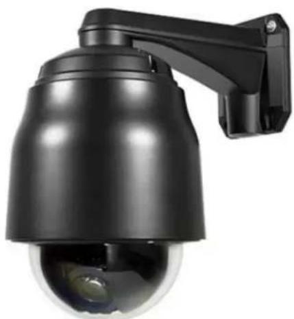
Black security camera with mounted arm and spherical lens (no text or symbols visible)User Manual
Firmware Version v1.0
Copyright ©2016, Marshall Electronics, Inc. All Rights Reserved. This document may not be copied.
Trademarks
Other trademarks used in this document are registered trademarks or manufacturer or vendor trademarks associated with the products.
Disclaimer
Product options and specifications can be changed without notice. The information in this manual is furnished for informational use only and should not be construed as a commitment by Marshall Electronics, Inc. Marshall Electronics, Inc. assumes no responsibility or liability for any errors or inaccuracies that may appear in this publication.
Safety Precaution
We appreciate your IP camera purchase. Before installing the product, please read the following with care.
Make sure to turn off the power before installing IP camera.
Do not install under direct sunlight or in dusty areas.
Make sure to use the product within the temperature and humidity specified.
Do not operate the product in presence of vibrations or strong magnetic fields.
Do not put electrically conducting materials in the ventilation hole.
Do not open the top cover of the products. It may cause a failure or electric shock on the components.
Make sure to leave a space of at least 10 cm from the ventilation hole in order to prevent overheating.
◇ Check voltage and current requirements before connecting a power supply.
1. Introduction......4
1.1 About this Manual....4
1.2 Features 4
1.3 System Connections....6
2. Installation......8
2.1 Connecting Power 8
2.2 Connecting Network 8
2.3 Connecting Video 8
2.4 Connecting Audio 8
2.5 Connecting Serial Ports 8
2.6 Connecting Sensor & Alarm 8
2.7 Check If It Works 9
3. System Operation....10
3.1 Remote Video Monitoring 10
3.2 Initialization of IP Address....12
4. Remote Configuration....13
4.1 System Configuration 13
4.2 Video & Audio Configuration....13
4.3 Image Configuration 19
4.4 Network Configuration....25
4.5 Event Configuration....39
4.6 Record Configuration....47
4.7 Device Configuration 53
4.8 PTZ Configuration 54
4.9 User Configuration....61
4.10 System Configuration....64
5. VS Manager 69
7. Data Sheet 70
8. Appendix ......72
1. Introducon
1.1 About this Manual
This User Manual provides information on installation setup, operation of the IP Camera, as well as troubleshooting tips.
1.2 Features
This product is a network-based box camera with live remote monitoring, audio monitoring and control via an IP network such as LAN, ADSL/VDSL, and wireless LAN.
Video
• Highly Efficient Compression Algorithm; H.264 & MJPEG support
- Wide range of Transmission Rates: 32kbps - 16mbps
- Various Transmission Modes: CBR, VBR, Hybrid
- Motion Detection
Audio
- Multi-Transmission Mode: Simplex (IP Camera to Client PC or Decoder/ Client PC or Decoder to IP Camera), Full Duplex
Network
• Fixed IP & Dynamic IP (DHCP) support
• 1:1, 1:N support
- Multicasting
- Various types of Protocol support : TCP/IP, UDP, Multicast, DHCP, SMTP, HTTP, SNMP, RTP, RTSP
- OnVIF, PSIA compliant
Serial Data
- RS-485 support
- Data Pass-Through Mode: Serial Data Communication between IP Camera and Decoder
Sensor and Alarm
• Supports direct connections of External Sensor and Alarm Devices
- Event Alarm
- If an external sensor is activated, camera can be set to move to the corresponding preset position
User Interface
- Diagnose and upgrade through dedicated program called VS Manager
High Reliability
- Reliable Embedded System
1. Introducon
Powerful Pan/Tilt Functions
• Maximum 360°/sec High Speed Pan/Tilt Motion.
- Pan/Tilt Motions are easily accomplished with Vector Drive Technology. Target view is reduced dramatically and the video on the monitor is very stable.
- When using a PTZ Controller, the ultra slow speed of 0.05^ / sec is useful for accurately moving the camera to a desired view. Additionally, the zoom-proportional pan/tilt movement improves the ability to follow a moving object.
Preset, Pattern, Swing, Group
- Maximum of 128 Presets are assignable and characteristics of each preset can be set up independently.
- Maximum of 8 sets of Swing Actions can be stored. This enables camera movement repetitively between two preset positions with a designated speed.
- Maximum of 4 Patterns can be recorded and played back. This enables camera movement to follow any trajectory operated by a joystick as closely as possible.
- Maximum of 8 Group Action Sets can be stored. This enables camera movement repetitively with a combination of Preset or Pattern or Swing. A Group is composed of a maximum of 20 Preset/Pattern/Swings entities.
PTZ (Pan/Tilt/Zoom) Control
- With RS-485 communication, a maximum of 255 Cameras can be controlled consecutively.
- Pelco-D or Pelco-P Protocol can be selected in the current firmware version.
Easy Installation and Perfect Outdoor Environment Compatibility
- Fans and heaters are built into the camera enclosure for both hot and cold temperature environments. Advanced mechanical design protects the camera from damaging water and dust.
- It is easy to install and maintain the camera with a cable channel built into the mountain brackets.
1. Introducon
1.3 System Connections
The IP Camera can be connected in one of two ways:
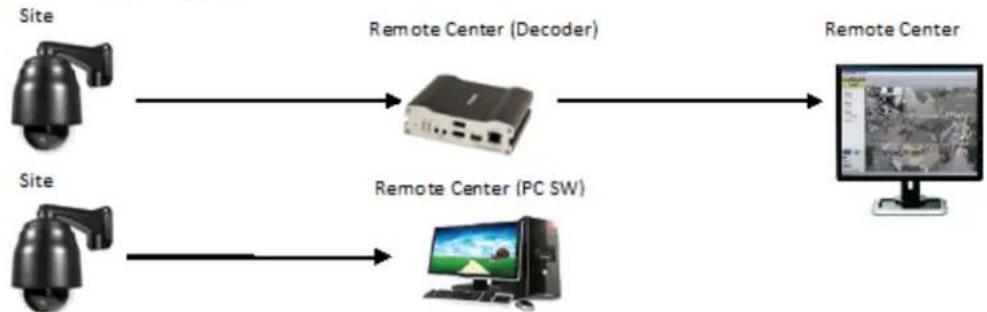
1) 1 to 1 connection where one camera is connected to one PC client or a decoder system, or 2) 1 to many connections where one system can be connected to several PCs and decoder systems (the video server can work as a video decoder which takes the data from a video server or IP camera, decodes and outputs analog video).
Topology
Generally, the IP Camera and PC or a Decoder is connected in a 1-to-1 mode or a 1-to many configuration:
- 1:1 Connection
flowchart
graph LR
    A["Site"] --> B["Remote Center (Decoder)"]
    C["Site"] --> D["Remote Center (PC SW)"]
    B --> E["Remote Center"]
    D --> E
One camera is installed at a site where video images are transmitted. A PC or a decoder is installed at a central location to receive and view the video images on an analog monitor. Audio and serial data are transferred in either direction.
- 1:N Connection
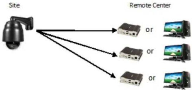
In this configuration, a site can be monitored from many remote central locations. Although up to 64 PCs or Decoders can be connected to one IP Camera, the maximum connections would be limited by network bandwidth connection. Functionally, the VMS (Video Management System) software provided can replace the decoder.
1. Introducon
Multicast Mode
If the network supports Multicasting, a large number of decoders can be used to receive video effectively using a single video and audio streaming. However, Multicast Mode is possible only when the network environment supports Multicast.
- Relay

flowchart
graph LR
    A["Site"] --> B["Center 1(Decoder)"]
    B --> C["Center 2 (Decoder)"]
In this arrangement, video and audio can be re-transmitted from one center to another center. The arrangement is useful when the network bandwidth at the site is limited while there is more than one center wanting to monitor the site.
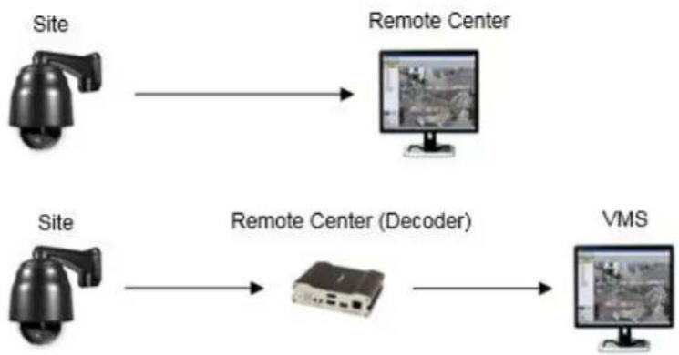
• VMS (Video Management System)
flowchart
graph LR
    A["Site"] --> B["Remote Center"]
    C["Site"] --> D["Remote Center (Decoder)"]
    D --> E["VMS"]
VMS (Video Management System) is a Windows based remote monitoring program to access multiple servers for real-time monitoring or control of the servers and connected cameras. Please refer to the VMS User Manual for more information on VMS.
2.1 Connecting Power
After confirming the Power Source, connect Power Adaptor and connect the 12VDC Connector to the System.
2.2 Connecting Network
Plug the Network Cable into the Ethernet port (RJ-45 network port).
2.3 Connecting Video
1) To display video through the composite or HD-SDI port, connect each port to a monitor using BNC coaxial cable. To display video through the HDMI port, connect the port to a monitor using the HDMI cable.
2) On the Video tab, the Enable Preview option should be set to "ON". (Please refer to the Video Configuration section for more details):
- Video cannot be viewed if the BNC coaxial cable is not connected when using HD-SDI.
- If the video transmission distance is too far away, the video data may not be transmitted due to a reduction in the video signal. In order to prevent this, install a repeater in the middle.
- When using HD-SDI, the video can be viewed on the HD-SDI monitor.
- When using HDMI, the video can be viewed on the monitor supporting HDMI.
2.4 Connecting Audio
Audio is Full-Duplex. It is possible to set the mode as Tx-only, Rx-only, or Tx-Rx.
- Connect audio input and output ports to audio devices accordingly.
- The Audio signal required is line level, so audio equipment with an amp, mixer or other amplifier should be used.
2.5 Connecting Serial Port (RS-485 Communication)
This IP PTZ Camera can be connected to external equipment such as a PT receiver, etc. The camera can send PT commands via the Serial Ports.
When a Decoder System is used to connect the IP PTZ Camera to the Serial Port, the Decoder System works in Pass-Through Mode (data from one port is delivered to the other port.
2.6 Connecting Sensor and Alarm
Connect Sensor and Alarm Devices to corresponding terminals accordingly.
2. Installaon
2.7 Check If It Works
Once the power is supplied to the camera, it will start booting. The system will boot up to operation mode after approximately 40-60 seconds. The green LED on the Ethernet Port will flash indicating the system is ready.
Software provided on the disc called VS Manager allows you to check the IP address and other network details of the camera. Please refer to the VS Manager manual for instructions on how to find the IP address of the camera and to make necessary changes.
3. System Operaon
3.1 Remote Video Monitoring
There are two ways to monitor video when the VMS (Video Management System) and IP Camera are connected. In order for a proper operation, an IP Address must be set accordingly. Please refer to the VS Manager Manual enclosed with product for further details.
| Default ID: admin | Default Password: 1234 |
Video Monitoring using Internet Explorer
Open Internet Explorer and enter the Camera's IP Address. The system will ask for confirmation to install Active-X Control. Once authorized, Internet Explorer will begin to display video images from the Camera as shown below:
Default IP Address : http://192.168.10.100
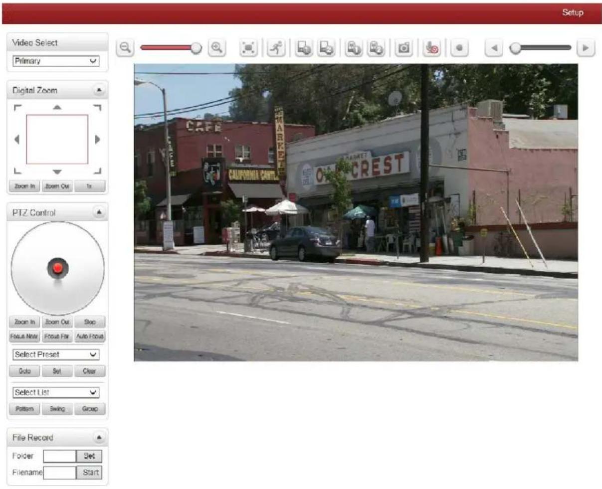
- Video Select
Select the Video Stream to be viewed: Primary, Secondary, Tertiary or Quartic Streaming This camera is capable of Dual Streaming; Primary Streaming and Secondary Streaming. Video will be displayed according to the resolution set on video configuration. If Dual Streaming (“Use Dual Encode” Menu in Video page) is not activated, Secondary Videos are not available.
- View Size
Adjust the Screen Size. Screen size is initially adjusted according to the Compression Resolution. If you click 50% icon, the whole screen size will be reduced to half size.

- Digital Zoom
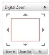
Control the Digital Zoom on the screen. The more the camera zooms in, the smaller the square of control panel is. Position of the image can be changed by moving position of the square. If you press “1x”, the screen will return to the normal size.
• PTZ Control (Optical Zoom & Digital Zoom Built-In Camera)
PTZ Control Panel is used for controlling External PTZ devices when the External PTZ devices are connected through a special Serial Port. It is possible to control zooming by using the Zoom In/Out buttons of PTZ Control Panel. In order to use Digital Zoom, select Digital Zoom "ON" in the Camera Tab)
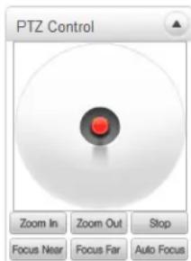
- "Stop"
Stop on-going action.
- “Focus Near”, “Focus Far”, “Auto Focus”
Adjust the focus of the lens.
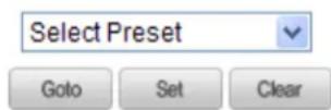
- Select Preset
Set preset position and move to the specific preset position.
-GoTo: After set up, move to the selected preset entry.
-Set: Set the current position to the selected preset entry.
-Clear: Delete the selected preset entry.
• Sensor Input and Alarm Input

Displays the status of the sensor in real time. This camera supports One Sensor Input. When the sensor of the camera is working, the sensor light turns red. Operate the Alarm Device by pressing the number icon. This
camera supports One Alarm Output. A number icon indicates the status of the alarm device.
- Snapshot
Capture video images and save them as BMP or JPEG files.

- Talk
Transfer audio from the PC microphone to the camera.

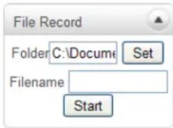
- File Record
Recording to an AVI file on Live View page is available. AVI files are generated in the specified folder or in specified file name on the PC where the web browser is running.
- Press "Set" button to select folder or create a new folder. Enter the file name on Filename field.
- Press "Start" button to start recording.
- Press "Stop" button to end recording.
- AVI file named "IP address_hh_mm_ss" or
"File name_IP address_hh_mm_ss" will be generated in the
specified folder depending on whether the path specified a folder or a prefix of the file name.
- Display Buffer


Set the number of video frames to be buffered before being displayed on web browser. Larger values result in
smoother video by sacrificing the latency. A setting of 10 \~ 15 frames can be generally used for most situations.
Video Monitoring with Decoder System
When the Camera's IP Address is set in the Remote IP Address section of the Decoder, the Decoder System will connect to the camera and start receiving the video images. Normally, a monitor connected to the decoder will display video images.
3.2 Initialization of IP address
If a System IP Address is lost, the system can be reset to the System Default IP Address using the Reset Button to the left of the LED lights.
- While system is in operation, press the reset button for more than 5 seconds.
- The system will reboot automatically.
- Once the system reboots, IP Address will be set to the System Default as below:
| • IP Mode | Fixed IP | • IP Address | 192.168.10.100 |
| • Subnet Mask | 255.255.255.0 | • Gateway | 192.168.10.1 |
| • Base Port | 2222 | • HTTP Port | 80 |
4. Remote Conguraon
4.1 System Configuration
Remote Setting is available by using web browser. Enter IP Address of the Camera and a Live View screen appears (see below). Press the Setup button located in the upper right area of the monitoring screen for Server Setup. For Remote Setting, the user should have manager-level authority or higher.
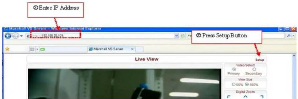
The configurations are grouped into 9 categories: Video & Audio, Image, Network, Event, Record, Device, PTZ, System, and User. To save configuration changes, click "Apply". Leaving the page without clicking "Apply" will discard any new changes.
4.2 Video & Audio Configuration Information
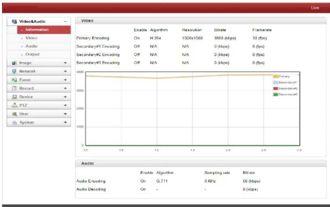
line
| Channel | Bitrate (kbps) | Resolution (x1080) | Enable | Algorithm | Sampling rate | Bitrate | | :--- | :--- | :--- | :--- | :--- | :--- | :--- | | Primary Encoding | 30 | 1920 | H.254 | 1920 | 3868 | 30 | | Secondary#1 Encoding | 0 | N/A | Off | N/A | N/A | 0 | | Secondary#2 Encoding | 0 | N/A | Off | N/A | N/A | 0 | | Secondary#3 Encoding | 0 | N/A | Off | N/A | N/A | 0 | | Audio Encoding | 56 (kbps) | - | G.711 | - | 8 KHz | - | | Audio Decoding | 0 (kbps) | - | - | - | - | 0 |The information provides current information for Video and Audio Settings.
4. Remote Conguraon
Video
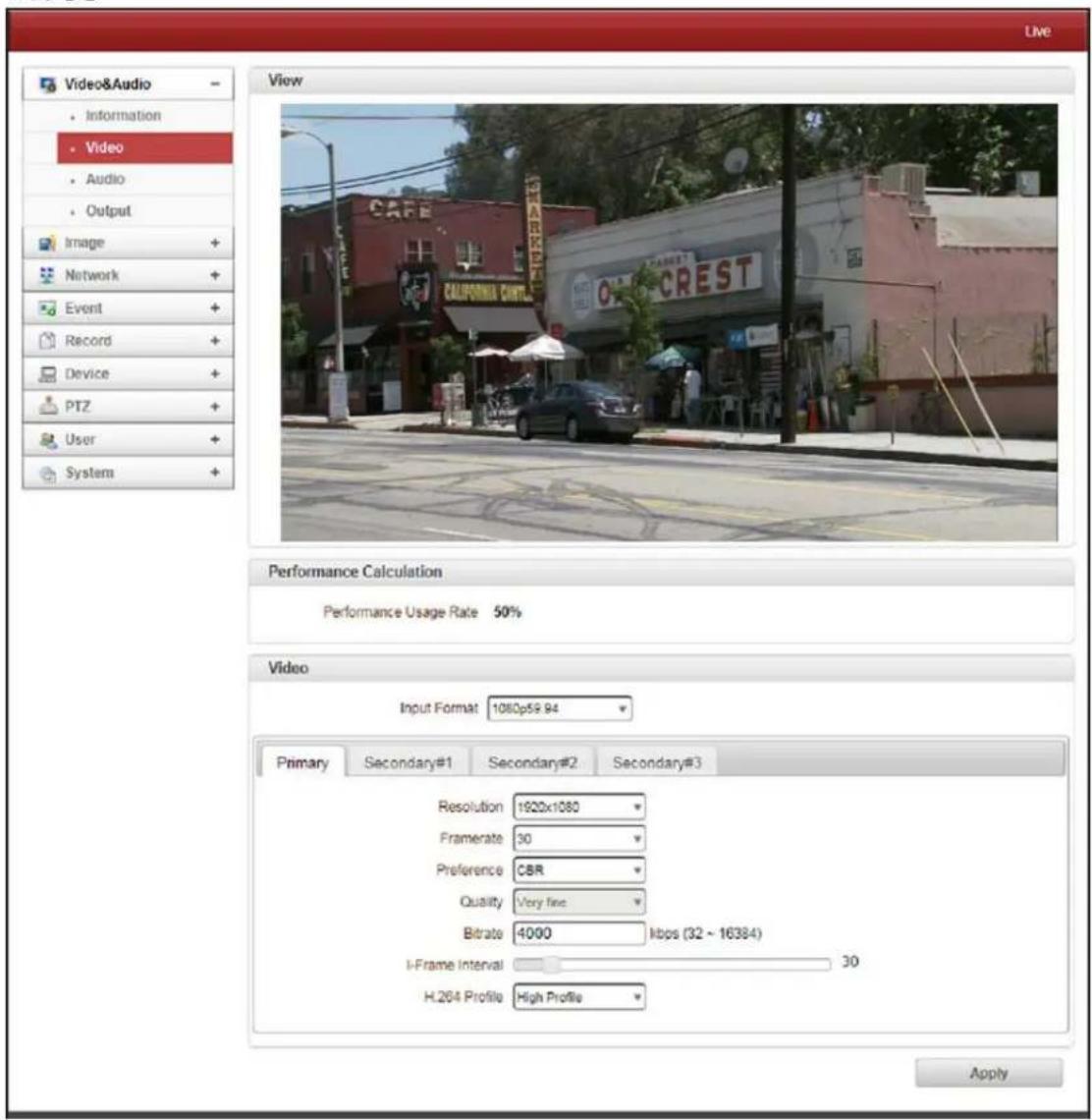
- Performance Calculation
Shows the performance usage rate according to the value set at for Encode mode.
- Input Format
Choose the appropriate Input Format from the list provided.
- Resolution
Select the appropriate Video Encoding Resolution. The Scaling option is used when the Encoding Resolution is different from Input Resolution. Without Scaling, the input video will be cut according to the encoding resolution. If Scaling is selected, the input video will be adjusted according to encoding resolution.
- Framerate
Determine the maximum number of frames per second for the video stream.
1,2,3,4,5,6,8,10,15,20,25,30 and 60 frame rate can be selected. The actual frame rate of the video can be less than the maximum frame rate set due to the network bandwidth limitation.
- Preference
Select Encoding Mode to control the video quality or bitrate: Quality (VBR) or Bit Rate (CBR). If Bitrate is selected, the video encoding will be prompted by the Bitrate value entered. Therefore, the Bitrate mode corresponds to CBR (Constant Bit Rate) encoding. If Quality is selected, the video encoding will be prompted by the quality of image selected. Therefore, Quality mode corresponds to VBR (Variable Bit Rate) encoding.
- Quality
Select Quality Level: 7 Levels of Quality are available. Quality Mode (VBR
Encoding) encodes every frame in a constant quality. Therefore, resulting bitrate may vary a lot depending on the complexity or activity changes in the input video. Quality Mode is preferred when constant video quality is required and the network bandwidth is enough for delivering the stream of highly varying bitrate.
- Bitrate
Bitrate value ranges between 32 and 16Mbps. Bitrate Mode (CBR Encoding) allows you to set a fixed target bitrate that consumes a predictable amount of bandwidth. In order to stay within the bitrate limit, video quality is controlled dynamically according to the complexity or activity changes in the input video.
- I-Frame Interval
I-Frame Interval ranges between 1 and 255.
- H.264 Profile
Select the H.264 Profile: High Profile or Baseline Profile
A profile defines the various capabilities which target specific applications.
1. High Profile
High Profile is the primary profile for broadcast and disc storage applications; particularly for high-definition television application.
2. Baseline Profile
Baseline Profile is for low-cost applications that require additional data loss robustness used in some videoconferencing and mobile application. This profile includes all the features that are supported in the constrained baseline profile, plus three additional features that can be used for loss robustness.
4. Remote Conguraon
Secondary 1, Secondary 2, Secondary 3
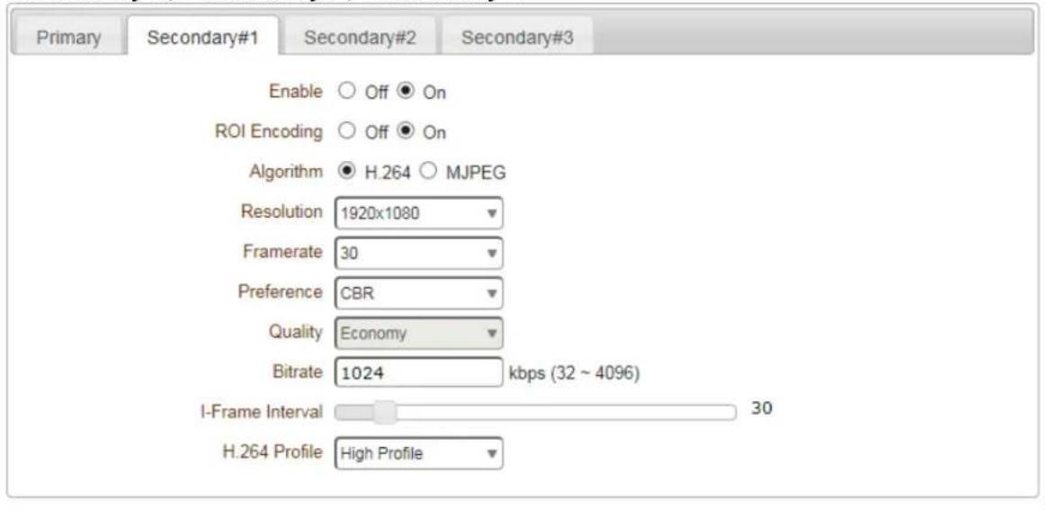
- Use Dual Encode
Select ON to Enable and use Secondary 1-3.
The Secondary 1-3 video can be viewed on Live View window by selecting Stream Number on the Video Selection
- ROI Encoding (Region of Interest)
Select ON to enable ROI. This can be selected on the secondary stream.
- Algorithm
Select H.264 or MJPEG for the Secondary, Tertiary or Quartic Streaming. With H.264, Bitrate Mode or Quality Mode can be selected for the Preference. MJPEG supports the Quality Mode only.
4. Remote Conguraon
Audio
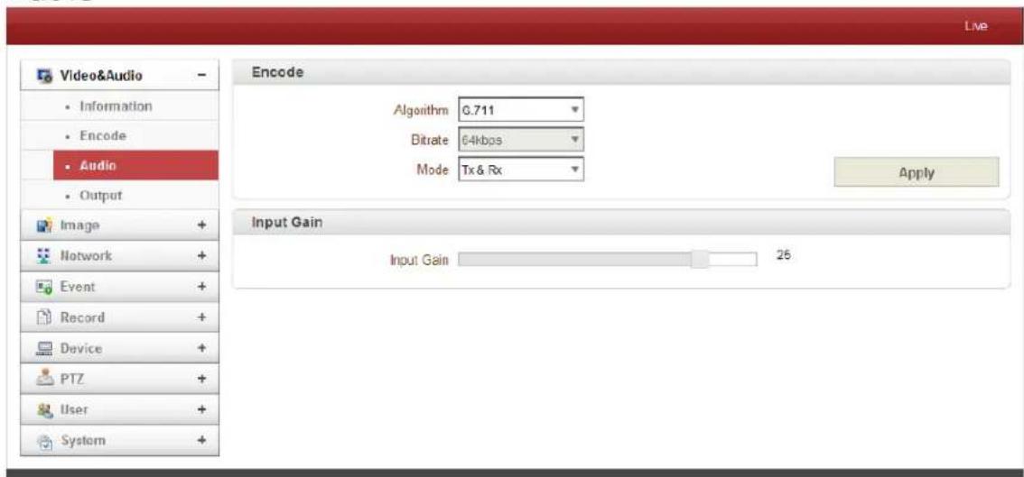
- Algorithm
Select the Audio Algorithm: G.711 or AAC. G.711 and AAC is supported from client to camera direction. However, bi-directional audio communication is supported.
- Bitrate
Bitrate ranges from 64Kbps and 128kbps when AAC is selected. The sample rate is fixed to 8KHz and 32KHz for G.711 and AAC respectively. Note: when the camera is connected to a decoder, the decoder's audio algorithm should be set identically to transmit the audio properly.
- Mode
Select the Audio Operation Mode:
| Mode | Action |
| Off | No Operation |
| Tx-Only | Transmit Only |
| Rx-Only | Receive Only |
| Tx & Rx | Transmit and Receive |
- Input Gain
Audio Input Gain ranges from 0 to 31.
4. Remote Conguraon
Output
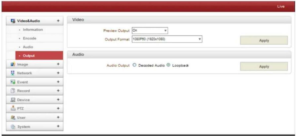
- Output Format
Chose Output Format when Enable Preview is selected.
- Audio
• Audio Output: The input audio is transmitted to the encoder.
- Loopback: Does not transmit the audio to the encoder. Audio input and output to the camera.
4. Remote Conguraon
4.3 Image Configuration

Day & Night
The IP Camera provides color images during the day. However, as light diminishes below a certain level, the camera can be set to automatically switch to night mode (black & white mode) for better image quality.
● Day & Night Mode: Selectable based on environment.
● Auto: Automatically switches to/from Day (color) or Night (B&W) Mode based on the lighting conditions using ICR (Infrared Cut Removal).
● Day (Color): Provides color image regardless of light.
● Night (B/W): Provides B/W image regardless of light.
White Balance
● White Balance Mode:
- Auto: This mode adjusts the white balance output using color information from the entire screen. It uses the color temperature radiating from a black subject based on a 3000K to 7500K range.
- Manual: Manual control of R and B gain, 256 steps each.
- Indoor: 3200K Base Mode.
- Outdoor: 5800 K Base Mode.
- Outdoor Auto: Provides automatic white balance output, especially for outdoors. Captures images with natural white balance in both the mornings and evenings.
- ATW (Auto Tracking WB): Auto Tracking White Balance (2000K to 10000K).
Auto Exposure
- AE Mode:
- Full Auto: Auto Iris and Gain, Fixed Shutter Speed (59.94/NTSC:1/60 sec, 50/PAL: 1/50 sec).
- Manual: 21 Shutter Speed, 18 Iris and 8 Gain steps can be set manually.
- Shutter Priority: 21 Shutter Speed steps (1/2 - 1/10,000) can be set manually. The Iris and Gain are set automatically based on the brightness of the subject.
- Iris Priority: 18 Iris steps (F1.8 to close) can be set manually. The Shutter Speed and Gain are set automatically based on the brightness of the subject.
- Bright: The Bright control function adjusts both the Gain and Iris using an internal algorithm based on the brightness level set by the user. Exposure is controlled by the Gain when subject is dark and controlled by the Iris when subject is bright. As both Gain and Iris are fixed, this mode is used when exposing at a fixed camera sensitivity.
- DSS Mode
Select Auto to operate DSS (Digital Sutter Speed)
● Back Light Compensation
The camera can balance the lighting in a scene with an extremely bright background such as sunlight. Adjusting the lighting contrast will show a clear image.
- Gamma Mode
Gamma correction can be changed in this mode.
Auto Focus
● Minimum Focus Length
Automatically uses Digital Zoom (12x) supported by the camera zoom lens. x10 Optical Zoom and x12 Digital Zoom lens (f=5.1 - 5.1mm) is built in camera.
- AF Sensitivity
- Normal: Focuses at the quickest speed. Use this mode when shooting a fast moving subject. Usually, this is the most appropriate mode.
- Low: Improves the focus stability. When the lighting level is low, the AF function does not work well to show a stable image.
- Focus Offset
Placing a dome cover in front of the camera may cause the focal distance of the camera to change. Although the camera responds to changes in this mode, this effect exceeds the AF range so it cannot track.
Enhancement
WDR
The Wide Dynamic Range mode is a function for dividing an image into a grid and correcting shadows and blown-out highlights in accordance with the intensity difference. It enables you to obtain images with a dark to light range, even when capturing a subject with a high intensity difference that is backlight or includes extremely light portions.
- Noise Reduction
The NR Function removes noise (both random and non-random) to provide a clear image. This function has six options: levels 1 to 5, plus OFF. The NR effect is applied in levels based on the gain and this value determines the limits of the effect. In bright conditions, changing the NR level will not have any effect.
- Stabilizer Mode
Turning on the image stabilizer function reduces image blurring caused by vibration, for example, which allows you to obtain images without much blurring.
- Defog Mode
When the surrounding area of the subject is foggy and low contrast, the defog mode will make the subject appear clearer.
4. Remote Conguraon
- Aperture Control
Aperture Control is a function which adjusts the edge enhancement of objects in the picture. There are 16 levels of adjustment, starting with “no enhancement”. When shooting text, this control may help by making the text sharper.
- Color Gain
Color Gain can be configured in this mode. Use this setting when bright colors are important. The settings range from 60% to 2000% with 15 stages total with 1000% being the standard.
● High Sensitivity
In this mode, the maximum gain increases enabling a brighter output even in a darker environment. However, if the gain reaches a high level (up to 4x), the image will have a large amount of noise.
Other
- Digital Zoom
Digital Zoom (12x) is supported by the camera zoom lens. x10 Optical Zoom and x12 Digital Zoom lens (f=5.1 \~ 5.1mm) is built-in the camera.
- Image Flip
Select On to enable a flipped image to be shown.
- Mirror
Select On to enable a mirrored image to be shown.
- Chroma Suppress
User can configure a Chroma suppress mode for low-illumination conditions. This can be useful when color noise is particularly noticeable in such conditions. Four levels (3 levels plus disable) are available for the Chroma Suppress mode.
Codec
- Brightness
Controls video input brightness by selecting values between 0 and 255.
- Contrast
Controls video input contrast by selecting values between 0 and 255.
- Saturation
Controls video input saturation by selecting values between 0 and 255.
4. Remote Conguraon
- Noise Filter
Noise Filter (NR) is used to obtain a high quality output image and enhance compression efficiency. This camera offers Edge Preserving 2D NR and Motion Adaptive 3D NR.
2D: use 2D NR at night mode with TDN (use 2D NR)
3D #1: use 3D#1 NR (refer to 1 on 3D NR)
3D #2: use 3D#2 NR (refer to 2 on 3D NR)
Strong: use 3D NR (refer to 2 on 3D NR). Effects are increased by 3 times more than normal 3D NR.
Blend: use 3D NR & 2D NR
- Edge Enhancement
Edge Enhancement is an image processing filter that enhances the edge contrast of an image or video in an attempt to improve its acutance (apparent sharpness).
- Edge Enhancement Sensitivity
User can adjust Edge Enhancement Sensitivity from 0 to 7 (with 7 being the highest sensitivity level).
● Edge Enhancement Strength
User can adjust Edge Enhancement Strength from 0 to 31 (with 31 being the highest strength level).
Schedule
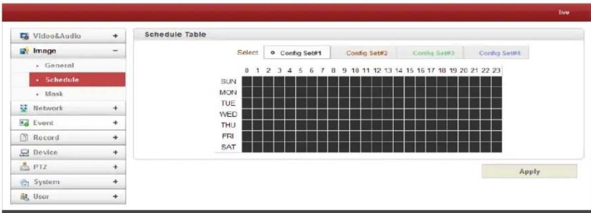
To allow different camera configurations according to time of a day, the scheduling feature of the camera allows user to define these configurations.
4. Remote Conguraon
- Configuration Set
4 different Configuration Sets can be programmed by opening "Config Set #1-4". For example, Config Set#1 can be configured for day mode and Config Set#2 can be configured for night mode.
- Scheduling Configurations
Cells in the weekly/hourly schedule table can be set to appropriate configurations by clicking a specific cell, an hourly cell, or a weekly cell.
Mask
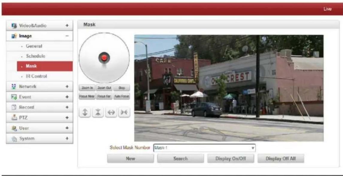
Masks can be displayed in the video.
- Position camera and select a mask from the drop down menu.
- Press the "New" button to get a new mask and adjust mask size.
- The specified mark can be shown by selecting the "Search" button.
4. Remote Conguraon
4.4 Network IP & Port Configuration
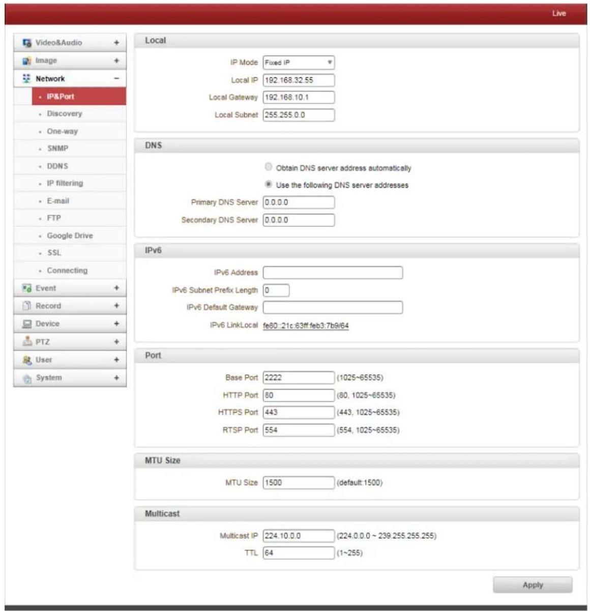
- Local
Select the IP Mode: Fixed IP or DHCP
Depending on the selected mode, the following configuration applies:
| IP Mode | Selection | Description |
| Fixed IP | Local IP | Fixed IP Address |
| Local Gateway | Gateway IP Address | |
| Local Subnet | Subnet Mask | |
| DHCP | N/A |
Contact your ISP provider or network manager for IP address information.
DNS
- Obtain DNS Server Address automatically
Find DNS Server Address automatically when IP Mode is set to DHCP.
- Use the following DNS Server Address
Enter the DNS Server IP Address: Primary or Secondary DNS Server
Domain Name System (DNS) is a database system that translates a computer's fully qualified domain name into an IP address. Networked computers use IP addresses to locate and connect to each other, but IP addresses can be difficult for people to remember. For example, on the web, it's much easier to remember the domain name www.amazon.com than it is to remember its corresponding IP address (207.171.166.48). Each organization that maintains a computer network will have at least one server handling DNS queries. That server, called a name server, will hold a list of all the IP addresses within its network, plus a cache of IP addresses for recently accessed computers outside the network.
IPv6
- IPv6 Address: Enter the designated lpv6 address.
- IPv6 Subnet Prefix Length: Enter the bit number for the lpv6 subnet.
- IPv6 Default Gateway: Enter the designated lpv6 gateway.
- IPv6 Link Local: Display the lpv6 link local.
Port
• Base Port (1025 - 65535)
Enter the Base Port Number: Network Base Port is used for communication with remote clients. In order for the IP Camera and remote systems to be connected, the port number must be identically configured for the IP Camera side and client side.
- HTTP Port (80, 1025 - 65535)
Enter HTTP port used for a web-based connection.
• HTTPS Port (443, 1025 - 65535)
Enter HTTPS port used for a secured HTTP connection.
• RTSP Port (554, 1025 - 65535)
Enter RTSP port used for RTSP-based connection. The default TRSP port is 554.
- RTSP (Real Time Streaming Protocol) is a standard for media streaming between server and client.
- Multicast
The Multicast menu is used for configuring the Multicast IP Address where the media stream is delivered when a Decoder, VMS or NVR software is connected in the Multicast Mode. The Multicast IP Address selection range is between 224.0.0.0 and 239.255.255.255. The selection can be used only when the media protocol is set to Multicast.
4. Remote Conguraon
Discovery
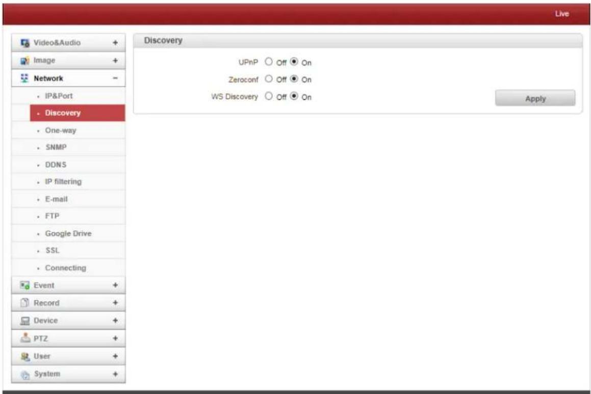
• UPNP
When UPNP is ON, it allows the discovery of the client according to UPNP (Universal Plug and Play) Protocol.
- Zeroconf
When Zeroconf is ON, it allows the discovery of the client according to Zeroconf Protocol.
- WS Discovery
Discovery function based on web service is enabled. It allows the discovery by the client SW which is supporting Onvif.
4. Remote Conguraon
One-Way
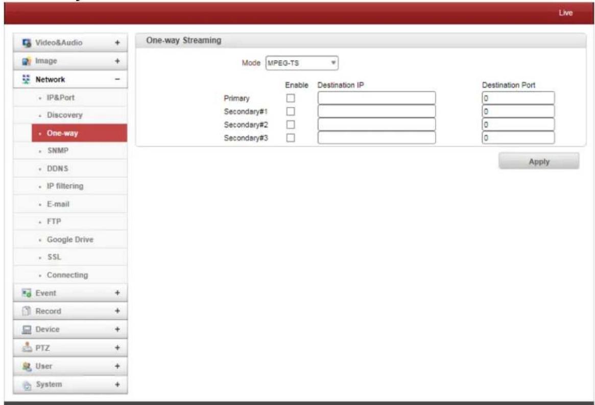
- This IP Camera provides two kinds of one-way (unidirectional) streaming based on UTP to clients: RTSP and MPEG-TS. Both are types of broadcasting where traffic from clients to a server is not generated at all.
- RTP (Real-Time Transport Protocol) is an Internet Protocol used for transmitting single real-time multimedia data such as audio and video to a select group of connected clients. Normally RTSP uses RTP to format packets of multimedia content. The RTP menu is used when the RTP only is streaming without an RTSP connection. RTP stream will be transmitted to the destination set. The SDP (Session Description Protocol) file can be found in the server and a client can retrieve it using the http connection.
- Destination IP: Set the IP Address of the destination system receiving the RTP Stream. If the system is a decoder, RTSP authentication information can be found in the middle of the RTSP URL: rtsp://admin:1234@192.168.10.100:554/video1
- Destination Port: Set the port of the destination system receiving the TRP stream.
- User Name: Enter the user name that will be used as a session name in the SDP file.
- File Name: Enter the file name that will be used as the name of the SDP file. When this is entered, it can be accessed through http://ServerAddress/filename
4. Remote Conguraon
- MPEG-TS is the standard format for the transmission and storage of audio, video, and data, and is used in broadcast systems such as DVB and ATSC. Transport Stream is specified in MPEG-2 Part 1 Systems (formally known as ISO/IEC standard 13818-1 or ITU-T Rec. H.222.0). Transport Stream specifies a container format encapsulating packetized elementary streams with error correction and stream synchronization features for maintaining transmission integrity when the signal is degraded. Although MPEG-TS supports AAC as the audio algorithm, only video is streamed when audio algorithm is set to G.711.
- Destination IP: Set the IP Address of the Destination System which will receive MPEG-TS stream.
- Destination Port: Set the Port of the Destination System which will receive MPEG-TS stream.
SNMP
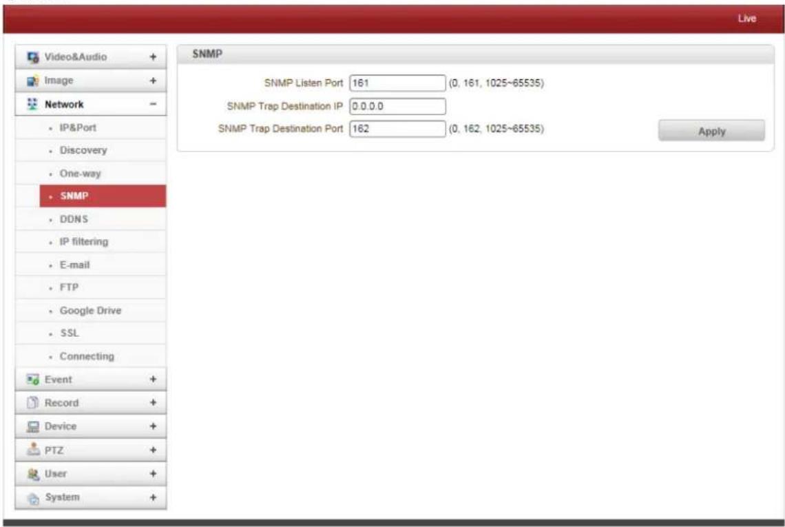
SNMP (Simple Network Management Protocol) is compatible with both SNMPv1 and SNMPvec. Settings for using SNMP are as follows:
4. Remote Conguraon
• SNMP Listen Port (0, 161, 1025 - 65535)
This port is for connecting an external device as an SNMP client. SNMP is not used when the value is 0.
• SNMP Trap Destination IP
Set the SNMP Trap Destination IP.
• SNMP Trap Destination Port (0, 162, 1025 - 65535)
Set the SNMP Trap Destination Port. SNMP is not used when the value is 0.
Simple Network Management Protocol (SNMP) is used by Network Management Systems to communicate with network elements. SNMP lets TCP/IP-Based Network Management clients use a TCP/IP-Based internetwork to exchange information about the configuration and status of nodes. SNMP can also generate trap messages used to report significant TCP/IP events asynchronously to interested clients. For Example: a router could send a message if one of its redundant power supplies fails or a printer could send an SNMP trap when it is out of paper.
DDNS
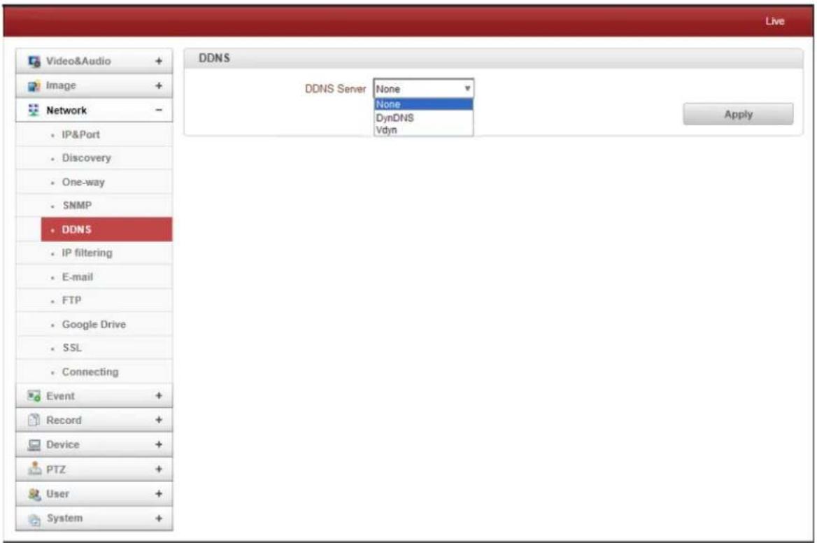
- DynDNS
DynDNS service is used in this mode. Refer to www.dyndns.org for details. ID, Password and Domain name are needed when DynDNS is set.
Dynamic DNS is a method, protocol, or network service that provides the capability for a networked device, such as a router or computer system using the Internet Protocol Suite, to notify a domain name server to change, in real time (ad-hoc) the active DNS configuration of its configured hostnames, addresses or other information stored in DNS.
4. Remote Conguraon
• Vdyn
Vdyn is a DDNS service provided by Visionica (hp://visionica.com). No further configuration is required for using this service. It internally uses the MAC address for the registration. When it succeeds, the domain name of the form
001C63A607EC.visionica.info is displayed on Current Domain entry of the Network page. Email setting is not mandatory.
- Check IP Disable
If “Check IP Disable” is selected, it will skip to check it’s own IP. In Fixed IP Mode, the set IP will be registered on the DDNS Server. In DHCP Mode, a dynamically assigned IP will be registered on the DDNS Server. Normally Check IP Disable should be unchecked in order to obtain the public IP in the network.
IP Filtering
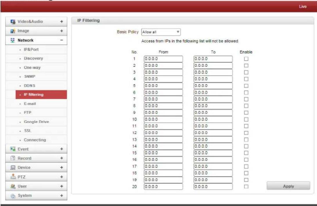
IP Filtering is simply a mechanism that decides which types of IP datagrams will be processed normally and which will be discarded.
4. Remote Conguraon
Email
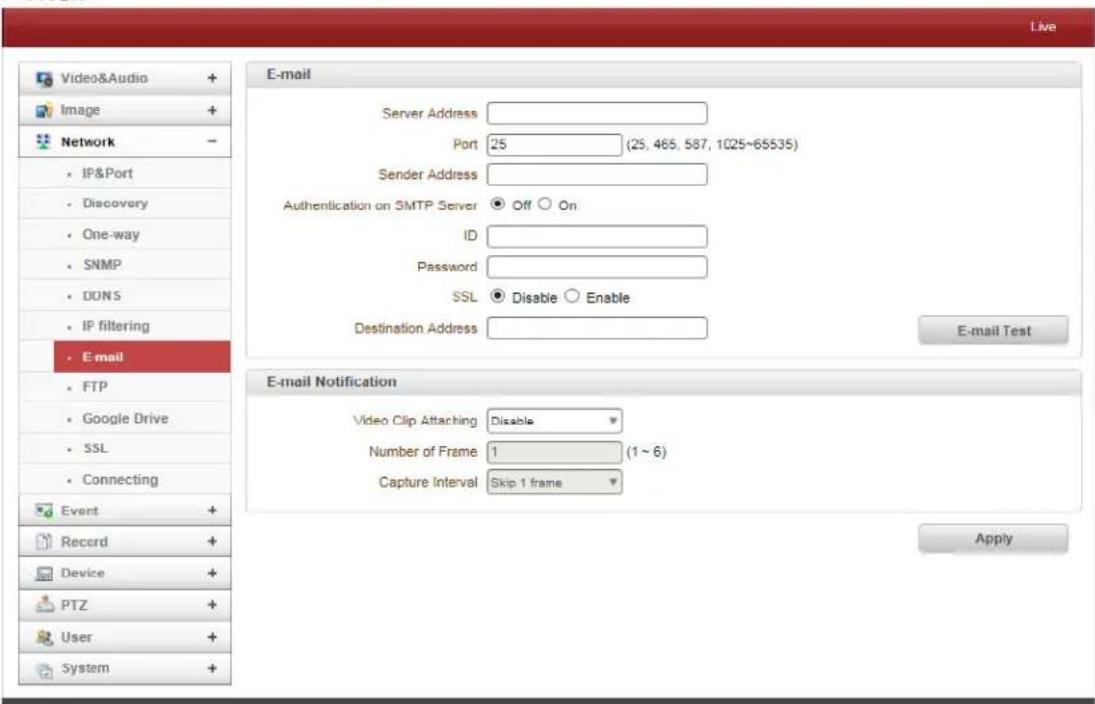
Select the following when Email is selected as an Event Action:
- Server Address
Enter an address of mail (SMTP) Server
- Port
Specify a port for SMTP operation (Port 25 is the default port in SMTP operation). If a port other that the default is configured in the SMTP Server, this port needs to be changed accordingly.
- Sender Address
Enter an account registered the in SMTP Server.
• Authentication on SMTP Server
This function is applicable when the Email Server requires authentication for sending Email.
- ID & Password
When the server requires authentication, ID and Password of an email account need to be entered.
- Destination Address
Enter Destination address. More than one address can be entered by delimiting comma (,) or semi-colon (;). Destination addresses can take up to 63 characters.
- Email Test
Email sending can be tested with this button. Please note that configured settings should be saved first by pressing the Apply button before using the Email Test Function. One of the following messages will appear as a result of the test:
4. Remote Conguraon
| Message | Description |
| E-mail sent successfully | Test E-mail has been sent successfully. Reception in the client can be checked. |
| Failed to connect SMTP server | Connection to the SMTP server failed. It is necessary to check if the server is reachable and server address and port are correct. |
| Authentication failed | The server is reachable but authentication failed. ID and/or password need to be checked. |
| SMTP server rejected the mail | The server is reachable, but mail sending failed due to a reason other than authentication. This error happens often when the server authenticates according to its own rule. For example, IP addresses of a specific range or addressed of a specific suffix are allowed. |
Email Notification
• Video Clip Attaching
Video clips can be saved and attached as an AVI or JPEG file. When dual encoding is enabled, Primary Video, Secondary Video (H.264 only) or JPEG Capture can be selected. The number of JPEG frames is configured appropriately. This setting is applicable only when JPEG Capture is selected.
- Capture Interval
Select the interval of the captured frame.
4. Remote Conguraon
FTP
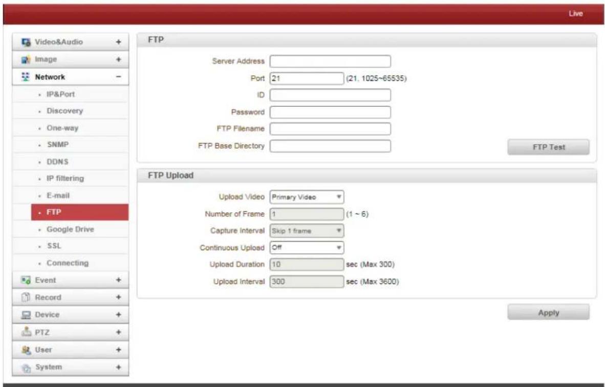
When FTP is selected, specify the following:
- Server Address
Enter an RTP Server Address to receive video files.
- Port
Specify a Port for the FTP operation (Port 21 is the default port in the FTP operation). If a port other than the default is configured in the FTP Server, this port needs to be changed accordingly.
• ID & Password
Enter ID and Password to access the FTP Server.
- FTP File Name
The File Names uploaded by FTP can be specified by the user. If a fixed name is specified, the file is overwritten repeatedly. Max length of a file name is 60 characters. If the name is left blank, file name is determined according to the internal rule implemented in the firmware. The following macros are supported to form variable parts of file names. These strings are case-sensitive.
■ %YYYY: year
- %MM: month
- %DD: day
- %hh: hour
- %mm: minute
- %ss: second
■ %EVENT: event type (Sensor1, Motion, ...)
- %ADDR: address of the server (Domain name when DDNS is used; otherwise IP address)
- “.avi” or “.jpg” will be added automatically to the filename depending on the video file type.
4. Remote Conguraon
- FTP Base Directory
Specify the name of the directory to be created in the FTP Server. It is valid only when Record is set to Use on the Record Session.
- FTP Test
The FTP upload function can be tested with this button. Please note that the configuration settings should be saved first by pressing the Apply button before using the FTP Test Function. One of the following messages will appear after testing:
| Message | Description |
| FTP connection tested successfully | The connection to the FTP server is successful. |
| Failed to connect FTP server | The connection to the FTP server failed. It is necessary to check if the server is reachable and server address and port are correct. |
| Authentication failed | The server is reachable but authentication failed. ID and/or password need to be checked. |
| Failed to upload file | File upload failed. The user of the ID is not allowed for writing into the directory or FTP server can be full. |
| Failed to erase file | Failed to delete the test file. The user of the ID doesn't have the privilege for file deletion. |
FTP Upload
- Upload Video
When using Primary, Secondary, Tertiary or Quartic Video (H.264 only), JPEG capture can be selected for uploading.
• Number of Frame
Enter the frame number of the JPEG capture (1 - 10).
- Capture Interval
Select the interval of captured frame.
• Continuous Upload
Continuous Upload ON allows video clips to be transmitted regularly regardless of the event occurrence. When this mode is activated, the FTP upload by event is suppressed.
- Upload Duration
Specify the recording duration of the video clip to be transmitted (max 300 sec).
- Upload Interval
Specify the transmission interval (max 3600 sec). Upload duration is not included in the upload interval. For Example: if the upload interval is 60 sec and the upload duration is 20 sec, a video clip for 20 sec is transmitted every 80 sec.
4. Remote Conguraon
Google Drive
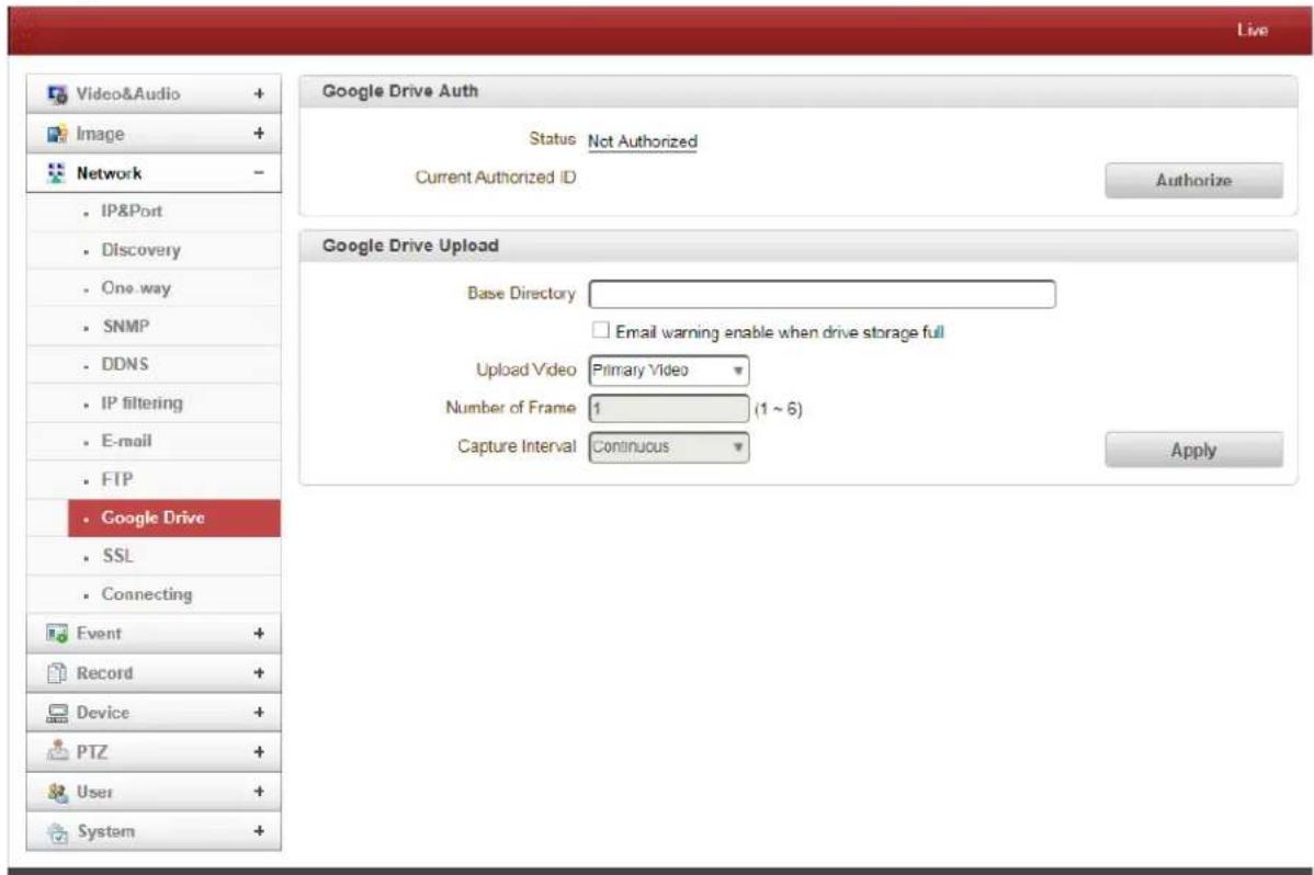
- Google Drive Auth
First, create Google ID and Password. Authorize ID and Password for uploading recorded data.
- Base Directory
Specify the name of the directory to be created in the Google Drive. Valid only when "Use On Record" session is used.
- Upload Video
Primary, Secondary, Tertiary or Quartic video (H.264 only) can be selected. JPEG capture can be selected for uploading.
• Number of Frames
Enter JPEG frame number (1-10).
- Capture Interval
Select interval type of captured frames.
4. Remote Conguraon
SSL
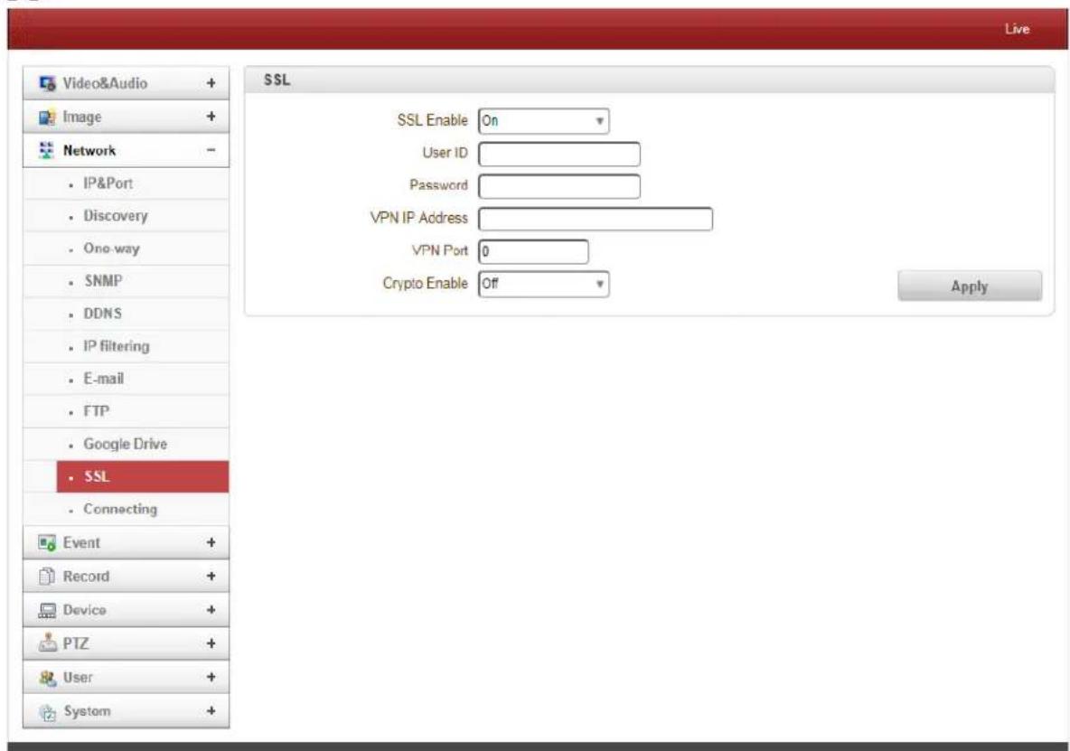
- SSL Enabled
SSL-VPN function will be enabled.
- User ID
Enter User ID for VPN Client.
- Password
Enter Password for VPN Client.
- VPN IP Address
Set IP Address on VPN.
- VPN Port
Set the Port on VPN.
4. Remote Conguraon
Connecting
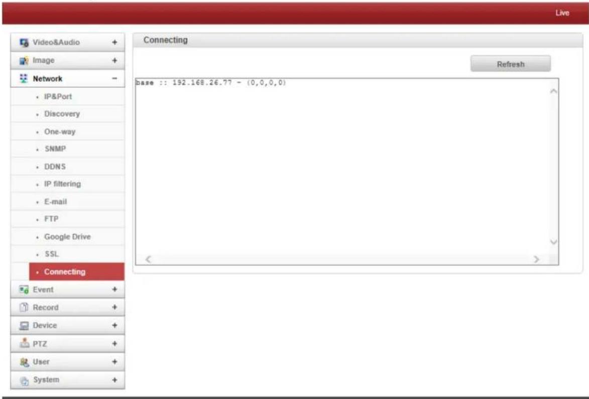
IP Addresses that are currently connected are listed here.
4. Remote Conguraon
4.5 Event Configuration
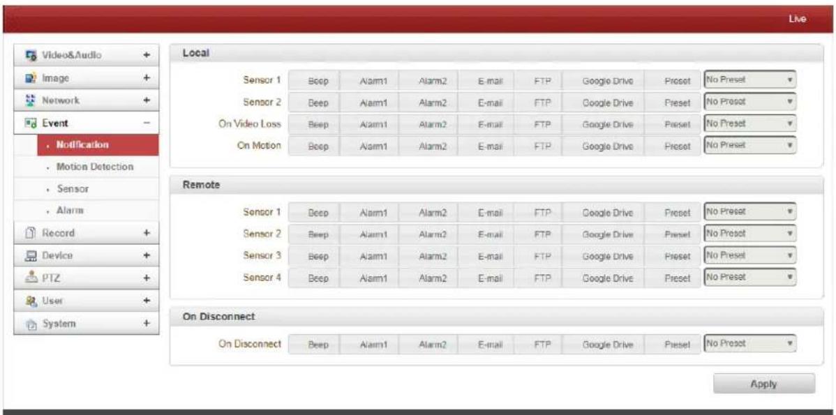
- Local Event Configuration
When a Decoder is connected to an IP Camera, one system becomes a Local System and the other a Remote System (generally a system which is being used by the user is called as Local System). Event Actions can be configured from the Remote System as well as the Local System. For Example: it is possible to turn on an alarm device in the Local (center) Decoder System when a sensor device in Remote (site) IP Camera is triggered. The Local section configures the actions for the events from the Local (self) System and the configuration activates the local devices and the Remote sections configure the actions for events from Remote (peer) System.
The following table lists the possible actions for the events:
| Action | Description |
| Alarm out | Triggers Alarm (Relay) Port |
| Sends Email to the specified Email Address; AVI File can be attached | |
| FTP | Upload AVI File to a specified FTP Server |
| Google Drive | Upload Google Drive storing through network |
| Preset | Move to the Preset Position |
- Local & Remote Event Configuration
- Sensor1 / Sensor2
Configure the actions when the sensor is activated. Multiple actions can be set for a single event.
- On Video Loss
Configure the actions when video input signal is lost. Multiple actions can be set for a single event.
4. Remote Conguraon
- On Motion
Configure the actions when motion is detected. Multiple actions can be set for a single event.
- On Disconnect
Configure the actions when the link (connection) with peer system is disconnected. Multiple actions can be set for a single event. This event happens when the last client which has been receiving video from the IP Camera loses the connection.
Motion Detection
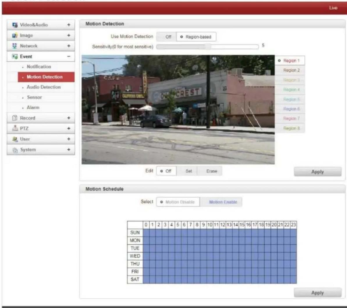
- Select the Use Motion Detection function
4. Remote Conguraon
- Motion Detection Area Editing
Configure the region for Motion Detection. Regions of arbitrary shapes can be configured by the following steps:
- Select Enable on Edit Tab.
- When selecting Editing Mode, Set includes the motion detection region cell and Erase is for excluding cells.
- Select cells by right clicking. Multiple cells can be selected by selecting and dragging.
- Press Apply Edit Area to save the selection.
Audio Detection
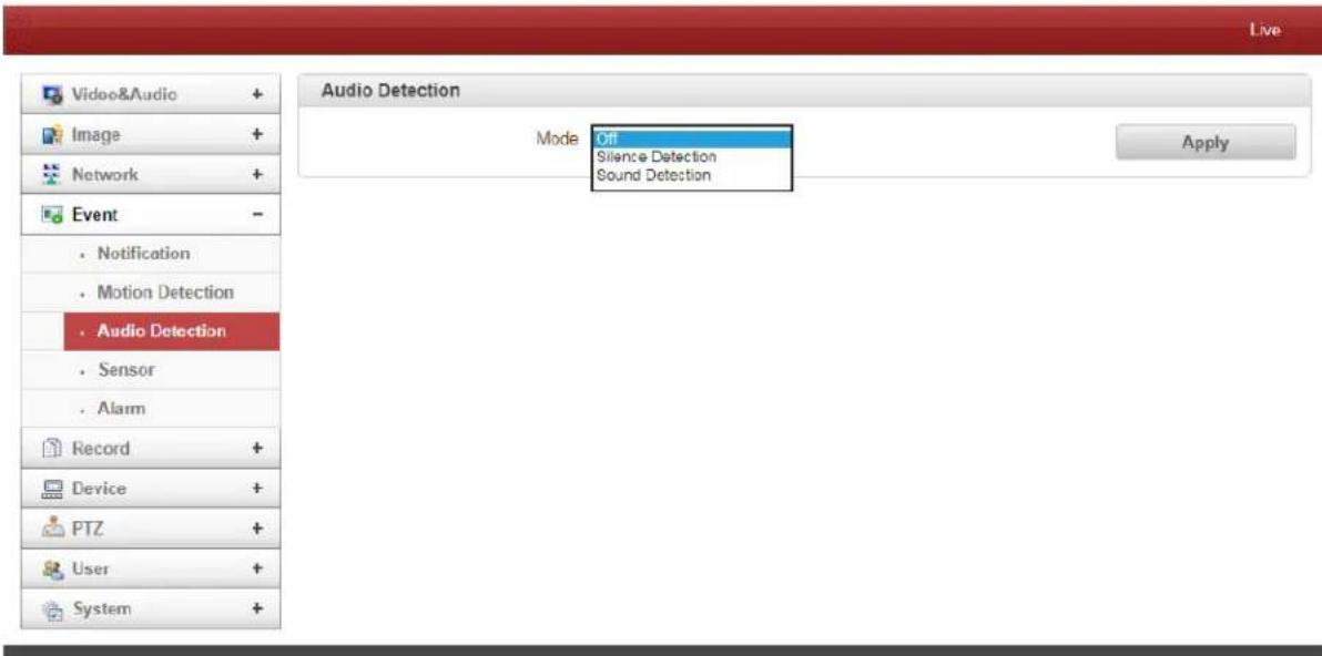
- Silence Detection
When silence is detected for a specific amount of time, an event is generated.
- Sound Detection
When sound is detected for a specific amount of time, an event is generated.
4. Remote Conguraon
Sensor
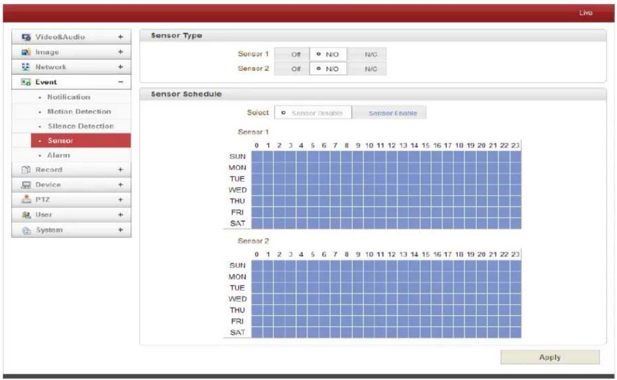
- Sensor Type
There are two Sensor Input Ports on the IP Camera. Each Sensor Port can be configured as follows:
| Function | Operation |
| OFF | Not used |
| NO (Normally Open) | The port is normally open and activated when closed |
| NC (Normally Closed) | The port is normally closed and activated when opened |
The function of the sensor port is set based on the type of the sensor connected.
- Sensor Schedule
Choose Sensor OFF or Sensor ON and make a selection on the Sensor Schedule Table to schedule according to day of the week and time.
4. Remote Conguraon
Alarm
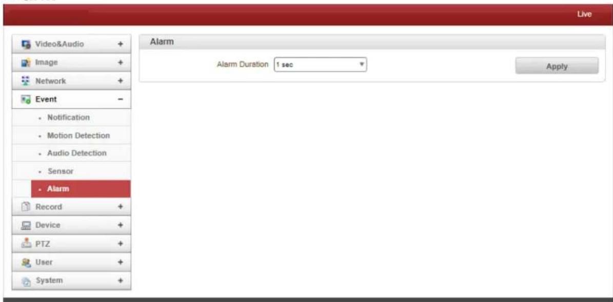
Set the duration of the Alarm or Beep Activation in case of an event. If Continuous is selected, the alarm will be in an active state until the operator resets it manually.
4. Remote Conguraon
Video Analytics
3 Types of Video Analytics are supported: Line Crossing Detection, Intrusion Detection and Camera Tampering Detection. Maximum encoding performance is restricted when video analytics is enabled. This should only be used when the performance usage rate for video encoding is 50% or less.
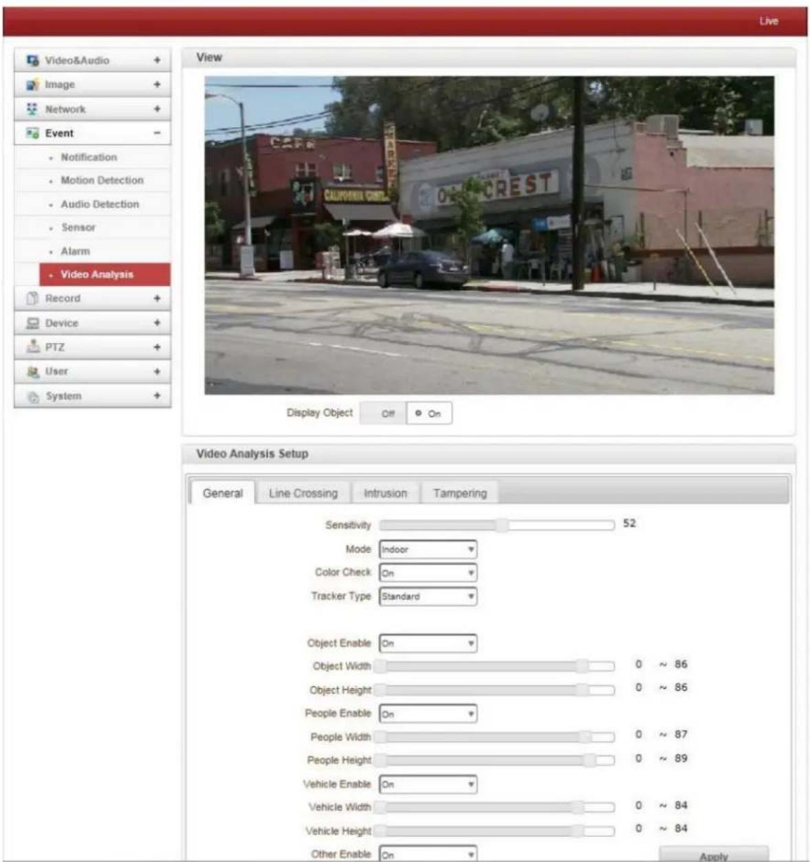
General
The General setting configures the video analytics parameters which are applied to all functions: Line Crossing, Intrusion, and Tampering.
4. Remote Conguraon
- Sensitivity
Configures the sensitivity in object detection: the larger, the more sensitive.
- Mode
Configures if the target scene will be indoor or outdoor.
- Color Check
Configures if the color property will be used in video analytics. "ON" is recommended.
- Tracker Type
Configures internal algorithm of object detection and tracking. Due to performance issues, "Simple" is recommended in most cases.
- Object Enable / Object Width / Object Height
"Object Enable" configures if any objects including people, vehicle and others are to be detected. "Object Width" and "Object Height" define minimum size of the object to be detected. When this setting is enabled, people detection and vehicle detection work regardless of the "People Enable" and "Vehicle Enable" setting.
● People Enable / People Width / People Height
"People Enable" configures if people are to be detected. "People Width" and "People Height" define the minimum size of the people to be detected.
● Vehicle Enable / Vehicle Width / Vehicle Height
"Vehicle Enable" configures if vehicles are to be detected. "Vehicle Width" and "Vehicle Height" define minimum size of the vehicle to be detected.
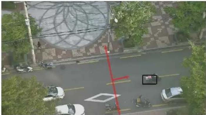
Line Crossing
A Line Segment is drawn in the configuration. When enabled, objects which cross the line are detected and events are generated accordingly.
- Camera Height
Configures the height of camera installation. This setting helps the internal operation of the object detection.
natural_image
Aerial view of a street intersection with vehicles and trees, featuring a large geometric sculpture on the sidewalk (no visible text or symbols)4. Remote Conguraon
Intrusion
The region for Intrusion Detection is drawn in the configuration. When objects enter that region, events are generated accordingly.
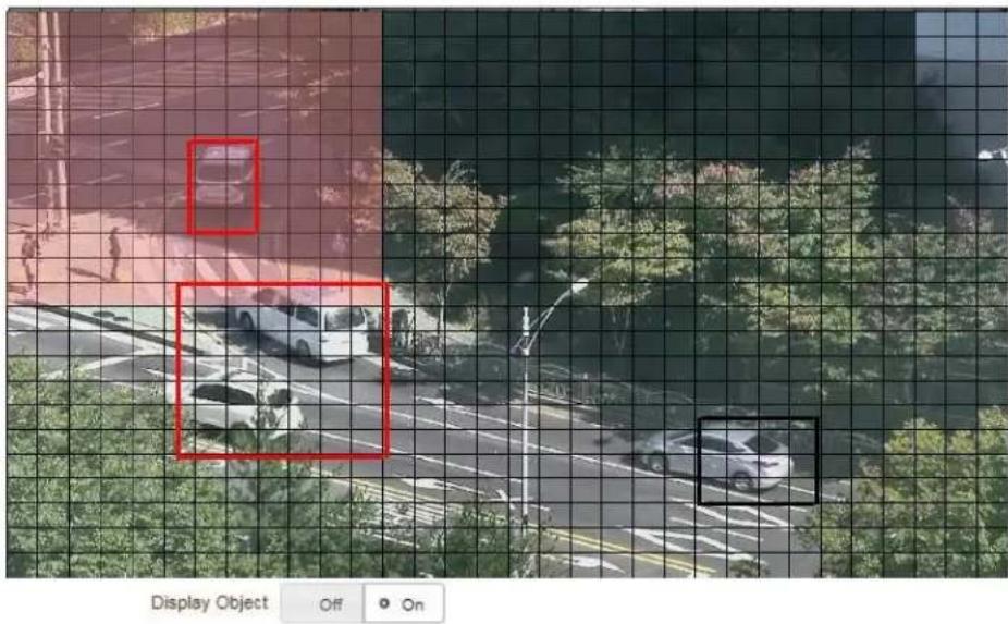
- Object Size
Defines the size of the object to be detected. Object size is defined by the percentage it covers in the total video size.
Tampering
When enabled, Camera Tampering, such as covering the lens with a towel, is detected and events are generated accordingly.
4. Remote Conguraon
4.6 Record Configuration
General
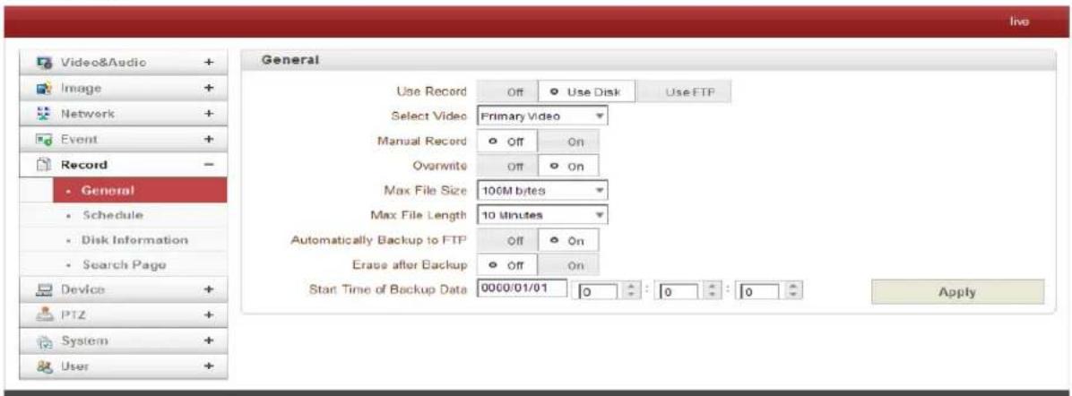
- Use Record
- Off: Recording function will not be used when OFF is selected.
- Use Disk: When the Use Disk function is on, the default setting for the Schedule
• Table is Record Off. - Use FTP: Recording will be enabled and data will be uploaded to an FTP Server. In this mode, the FTP Upload by Event is automatically disabled.
- Select Video
Select the Video Stream to record.
- Manual Record
When ON is selected, record is initiated regardless of Schedule.
- Overwrite
When the disk becomes full, the oldest data files are deleted automatically. This is valid only when Use Record is set to Use Disk.
• Max File Size / Max File Length
Max File Size option is for limiting the size of the AVI file. If Small File Size is selected, the file is generated but the number of small files will be increased. When limiting the time length of the AVI file, the Max File Length option is used. If the file size becomes the Max File Size or the duration of the recording reaches Max File Length, a new file is created.
• Automatically Backup to FTP
Data recorded in the disk can be uploaded to an FTP Server automatically for backup. FTP Server is configured on the Event page. This is valid only when Use Record is set to Use Disk.
4. Remote Conguraon
- Erase After Backup
Data is deleted automatically after being uploaded to the FTP Server. This is valid only when Automatically Backup to FTP is selected.
- Start Time of Backup Data
Specify the time when the data backup occurs. Select Backup to FTP Disk. This time is changed automatically with the Backup to FTP Server. Check current backup status on a regular basis. This is valid only when Automatically Backup to FTP is selected.
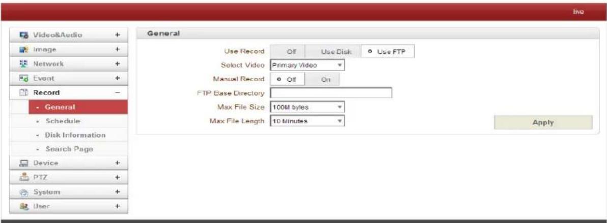
- FTP Base Directory
Specify the name of the directory to be created in the FTP Server. This is valid only when Use Record is set to Use FTP.
Checking Status of Recording
Recording Status can be checked on the main view page.

4. Remote Conguraon
Schedule
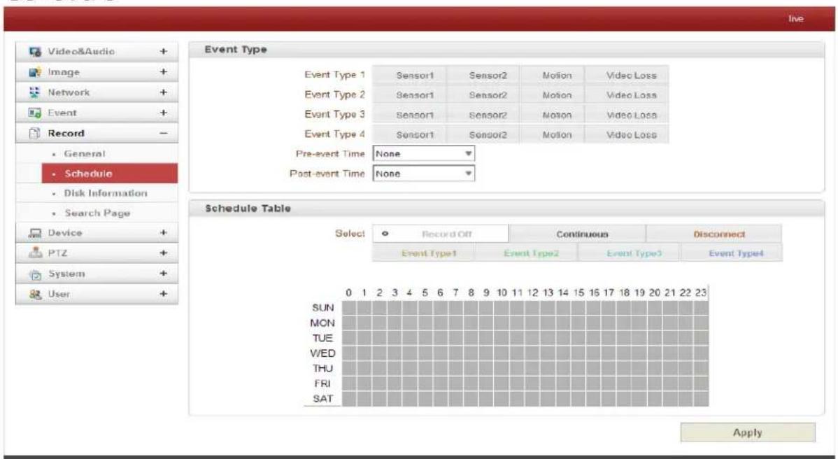
- Event Type
Three recording modes are supported: Continuous, Event, and Disconnect. When using Event Recording, Event Types can be selected among several Events. Selected Event Type is used for configuring the Schedule Table. Up to 4 Event Types can be configured and each Event Type can be a combination of Sensor, Video Loss and Motion Event.
- Pre-Event Time
Specify the duration of recording before an Event happens.
- Post-Event Time
Specify the duration after the Event is cleared.
- Schedule Table
Actual Recording Mode is determined by Schedule Table, where the Recording Mode is configured by Day and Hour. Recording Modes are configured as follows:
- Record Off
No Recording.
- Continuous
Records continuously.
- Disconnect
Recording is started when the system loses connection to the last client (Decoder, VMS/NVR) etc. When there are multiple clients and only one is disconnected, the recording is not started.
- Event Type
A recording is started when an Event is configured in the Event Type.
4. Remote Conguraon
Disk Information
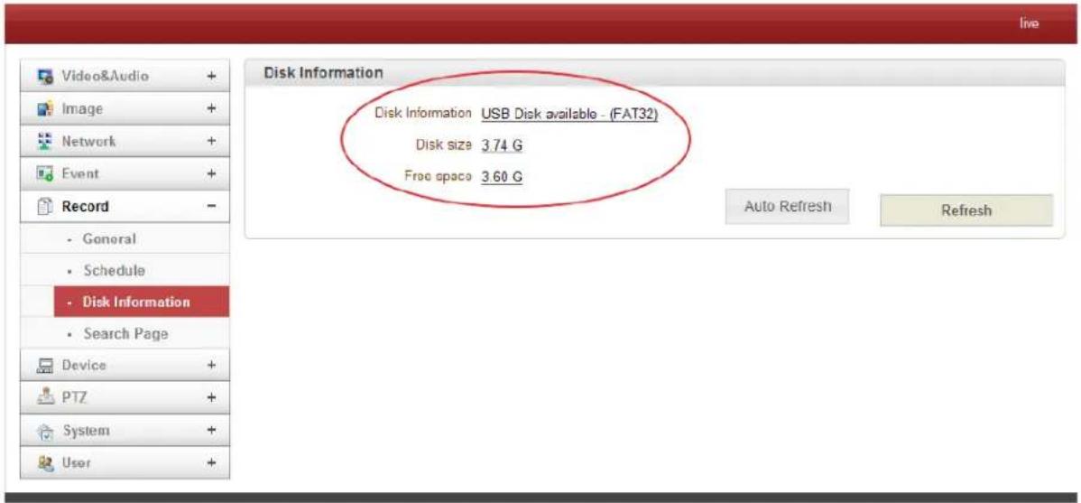
When SD Memory is used, at least 1GB is recommended. An EXT3 or FAT32 File System can be used. EXT3 or FAT32 can be read in Linux PC. However, only disks with FAT32 file system can be read in Windows PC. Less than 4Mbps of video bit rate is recommended when you record and monitor video simultaneously since frame dropping may occur due to performance limitation.
Restart the system after connecting an SD card. The system reads the disk status and initializes during reboot. Once the disk initialization is finished, the disk status is shown on the Record page of the web-based setup.
Refer to this chart for checking the disk status:
| Disk status | Description |
| Disk error detected | Error |
| No disk | Disk is not connected to the system. |
| Searching Disk information | Checking the status of disk. Refresh the page and wait until the status is changed. |
| Mounting and Recovering Disk... | Performing recovery process when disk damage is found. It takes from seconds to minutes for recovering. |
| Disk format needed | Disk is attached, but the type of the file system is unknown or damaged. |
| Unknown disk type detected | |
| USB Disk available | Available to be used for recording |
| Disk removed or in abnormal state | Disk is detached during operation or there is damage on the file system. If it happens while disk is connected, it is recommended to format the disk. |
4. Remote Conguraon
Search Page
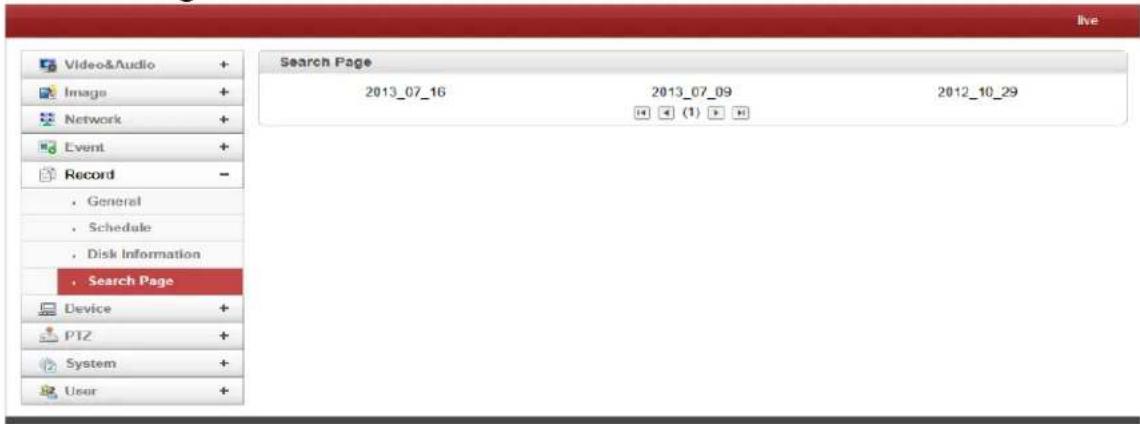
Recorded Video and Audio Data can be saved in AVI Format. In general, one AVI file is created for an Event-Based Recording. However, it is possible that a Series of Events can be recorded continuously and merged into a single AVI file depending on Pre/Post Event Time Setting. The size of file is limited to 10-2GB. With Continuous Recording, AVI files are created in a series and each size is limited to 10-2GB.
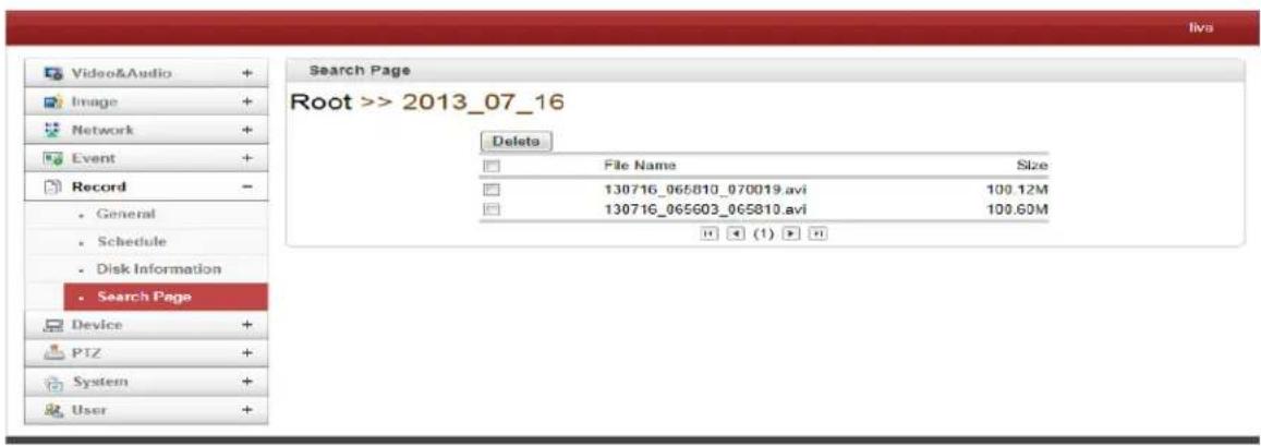
- Playback
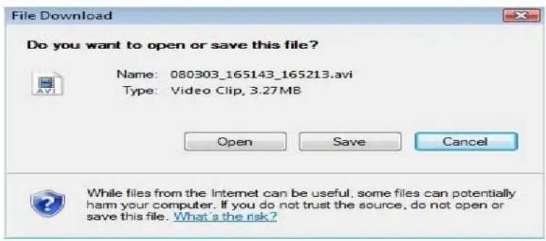
- After selecting an AVI file, a window will appear for opening or saving the file.
4. Remote Conguraon
-
The Save button will store the file in the PC. The AVI file can be played with Windows Media Player.
-
The Open button will download and automatically play with Windows Media Player.
- The internet connection is disabled during downloading. Two AVI files cannot be download at the same time.
4. Remote Conguraon
4.7 Device Configuration
Information
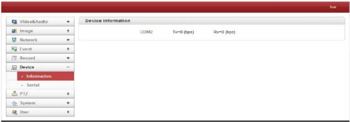
This information provides current serial communication status.
Serial
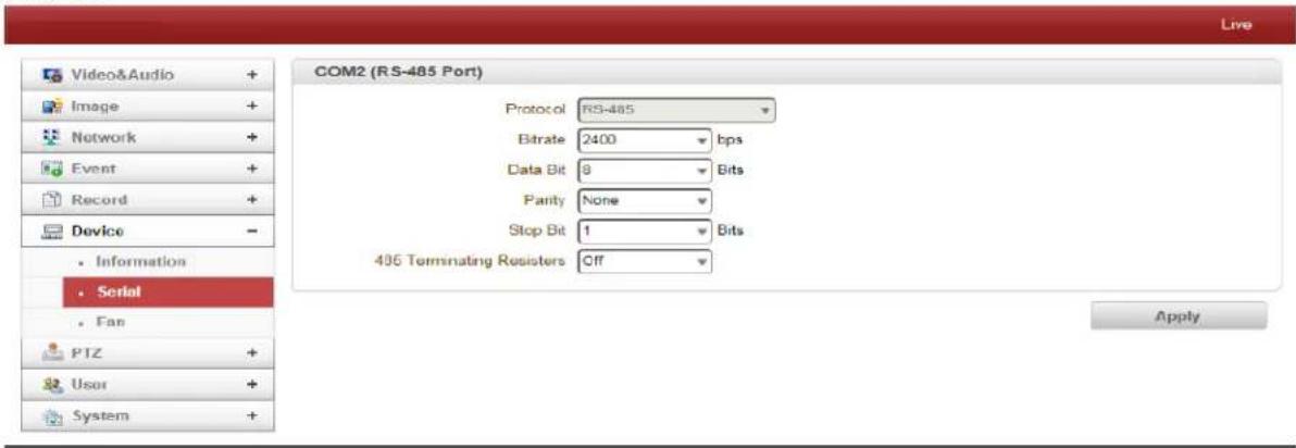
- Serial Protocol:
This IP Camera supports one Serial Port: RS-485.
- Serial Port Configuration:
The serial port configuration must be configured the same as the connecting device.
4. Remote Conguraon
4.8 PTZ Configuration
General
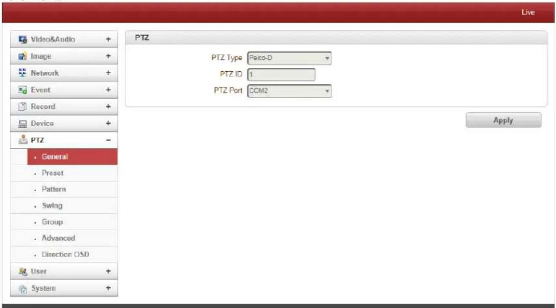
- PTZ Type
Select the type of PTZ Camera or Receiver.
- PTZ ID
Since it is possible to control multiple PTZ Cameras or Receivers with a single control line, each Camera or Receiver will be assigned with a unique ID. Enter the PTZ ID for control. The ID value range can be between 0 and 255.
- PTZ Port
Select the Serial Port for PTZ Camera control.
4. Remote Conguraon
Preset
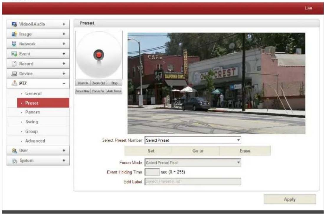
A max of 128 preset positions can be defined.
- Select Preset Number: Select entry to be assigned to the current server position.
-
Focus Mode: Select the Focus Mode after Preset Go To is selected.
-
Do Not Change: The current Focus Mode is not changed.
- Focus Auto: Auto-focusing is selected after the Preset is moved.
• Focus Manual: The current Focus Position is saved when Preset is set.
- Event Holding Time: Set the time to stay at the Preset Position when the Preset is moved by the Event. If it is set to 0, the server doesn't return to the original position after moving to the Preset Position by Event.
- Edit Label: Assign a Label to the Preset Position. Only the first 15 Preset Entries can have Assigned Labels (Preset-1 - Preset-15).
4. Remote Conguraon
Swing
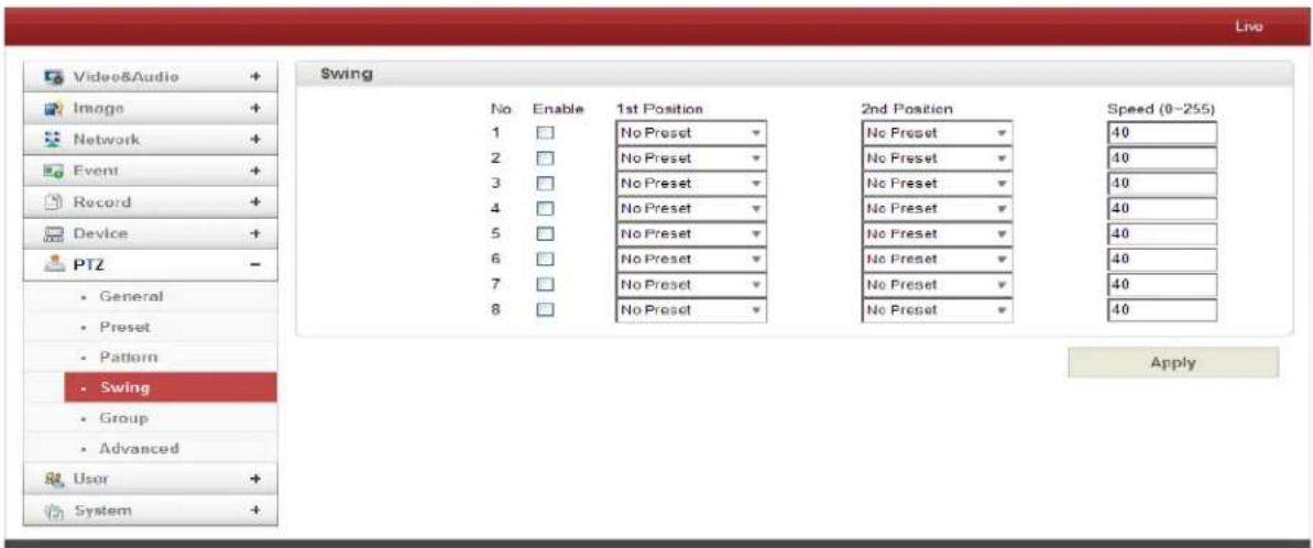
The Swing Function moves the camera between 2 preset positions repeatedly. When the Swing Function is enabled, the camera moves from the 1^st preset point to the 2^nd preset point in a CW (Clockwise) direction. Then camera moves from the 2^nd preset point to the 1^st preset point in a CCW (Counterclockwise) direction.

flowchart
graph TD
    A["1st Preset"] -->|CW Direction| B["2nd Preset"]
    B -->|CCW Direction| A
If the 1st point is the same as the 2nd point, the camera turns on its axis by 360^ in a CW (Clockwise) direction and then it turns on its axis by 360^ in a CCW (Counterclockwise) direction.
- Check Enable box
- Select the Preset for 1st Position and 2nd Position
- Enter the Speed (0-255)
- Press Save Swing button to save the Swing
4. Remote Conguraon
Group
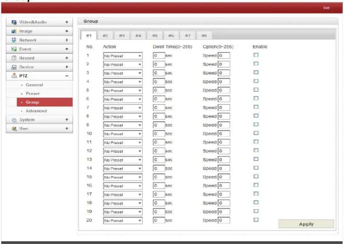
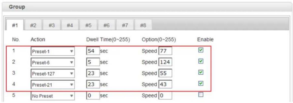
The IP Camera memorizes the combination of Presets, Pattern and/or Swings sequentially and runs Presets, Pattern and/or Swings repetitively on activation. A max of 8 Groups are programmable. Each Group can have a max of 20 actions which are the combinations of Preset, Pattern and Swing. The Option field is different for Preset and Pattern/Swing. For Preset, it configures the Preset Speed. For Pattern/Swing, it configures the number of repetitions. Dwell time between actions can be set up as well.
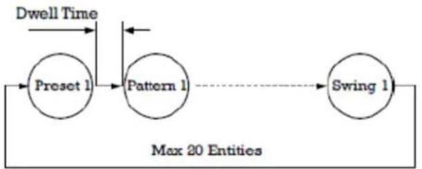
flowchart
graph LR
    A["Preset 1"] --> B["Pattern 1"]
    B --> C["Swing 1"]
    D["Dwell Time"] --> A
    style A fill:#fff,stroke:#000
    style B fill:#fff,stroke:#000
    style C fill:#fff,stroke:#000
    note right of B "Max 20 Entities"
- Select one Entry within Group.
- Select the Modify Group button. The following window will appear.
- Set Action, Dwell Time and Option and click Enable.
- Press Apply button and the Group can be used on the Live View Page.
4. Remote Conguraon
Advanced
Advanced
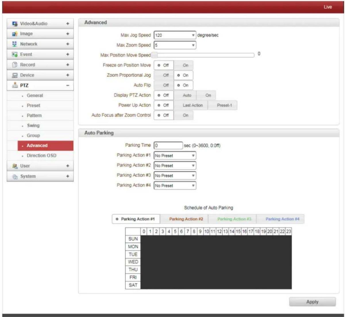
• Max Jog Speed: Jog Speed ranges from 30-360, Unlim.
- Max Zoom Speed: Eight level options on zoom speed.
- Max Position Move Speed: Slider scale sets the Position Move Speed.
- Freeze on Position Move
When PTZ Freeze on Position is selected, the video is stopped and that frame is displayed. Once PTZ Freeze is turned off, the video will resume to the current position.
• Zoom Proportional Jog
When Zoom Proportional Jog is ON, the Pan/Tilt speed can be set automatically after zoom in.
- Auto Flip
ON: When the tilt angle is set at the top of the tilt orbit, the zoom module turns on its axis by 180 degrees and moves to opposite tilt direction to keep tracking targets.
OFF: More than 90 degree tilt moving is not available.
- Display PTZ Action
PTZ Control Action such as Preset, Pattern, Swing or Group, can be displayed on top of the live display. The information is displayed with Burn-In OSD in the stream and all devices will see this information.
- Power Up Action: Specify if the camera will continue the previous actions such as pattern, swing or group after it is rebooted.
- Group-1: After reboot, start to Group-1.
- Preset-1: After reboot, start to Preset-1.
- Off: Moves to the initial position after rebooting.
- Autofocus after Zoom Control : Zoom in/out auto focus will be controlled automatically
Auto Parking
Auto Parking returns to the previous Preset Position or resumes the operation such as Pattern, Swing or Group when a specified time expires after the PTZ control is stopped. Parking Time can be set from 0 to 3600 seconds and "0" means that the Auto Parking function is turned OFF.
4. Remote Conguraon
Direction OSD (Only PT System)
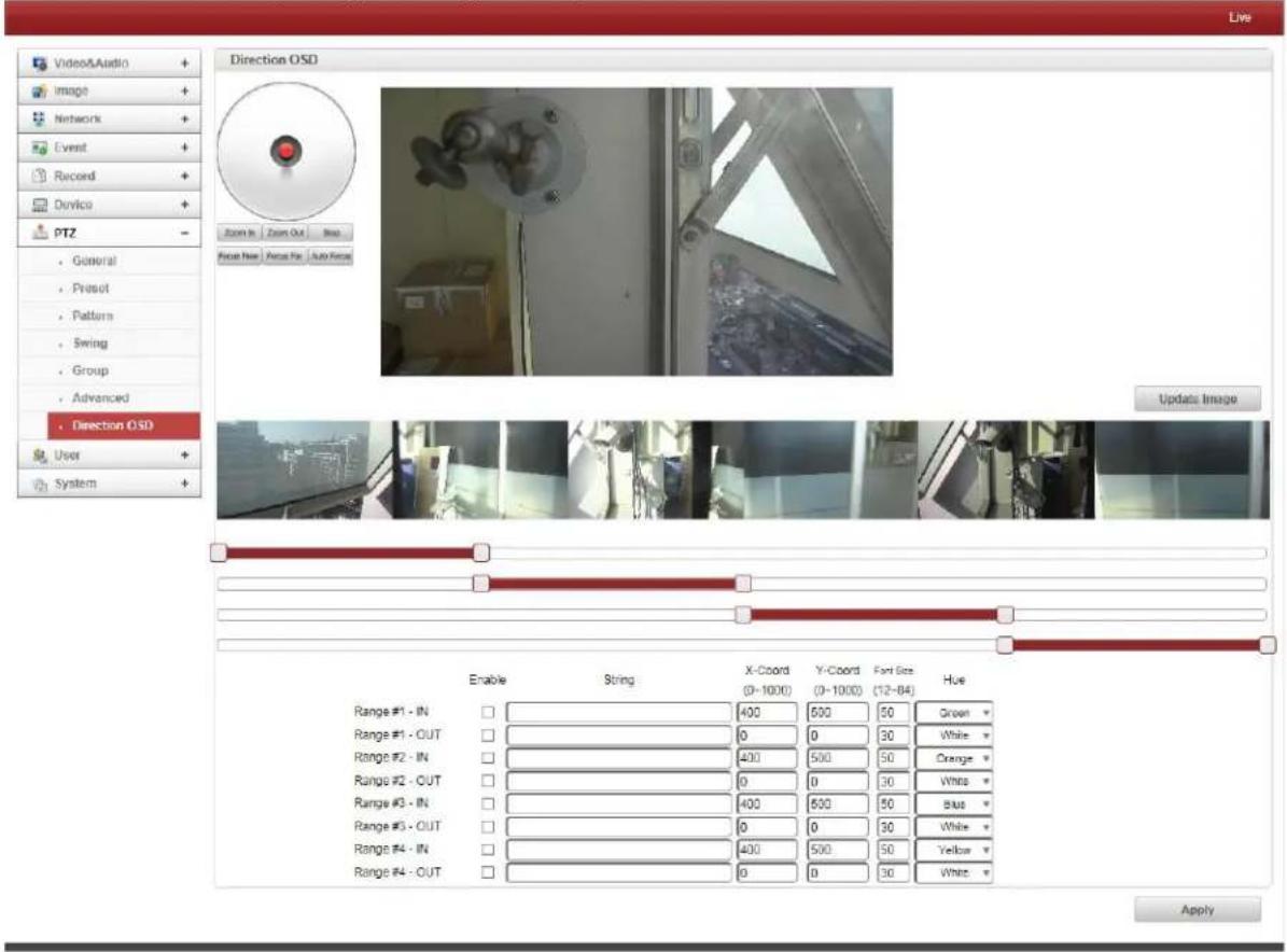
• 360 degrees panoramic shot.
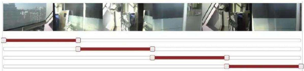
- User can select areas for OSD.
natural_image
Interior view of a modern office with glass windows and window, showing three horizontal red bars (no text or symbols visible)- Range # - IN: Based on Coordinate Value, user can see specific OSD.
- Range # - ON: Regardless of Coordinate Value, user can see specific OSD.
• X - Coord: Position of Horizontal Coordinate.
• Y - Coord: Position of Vertical Coordinate. - Font size: Select Font Size.
- Hue: Select Color.
4. Remote Conguraon
4.9 User Configuration
User List
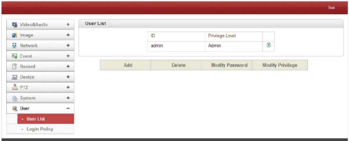
User can be registered and privilege level of a user can be specified. User configuration is allowed only to admin user. Max 16 users can be registered and each user can have one of four privileges.
| Privilege | Allowed Operations | Remarks |
| Admin | All Operations | User ID = admin |
| Manager | All Operations except for User Configuration | |
| User | Live Viewing and PTZ Control | |
| Guest | Live Viewing Only |
- Add User
Press Add button. The following window will appear.
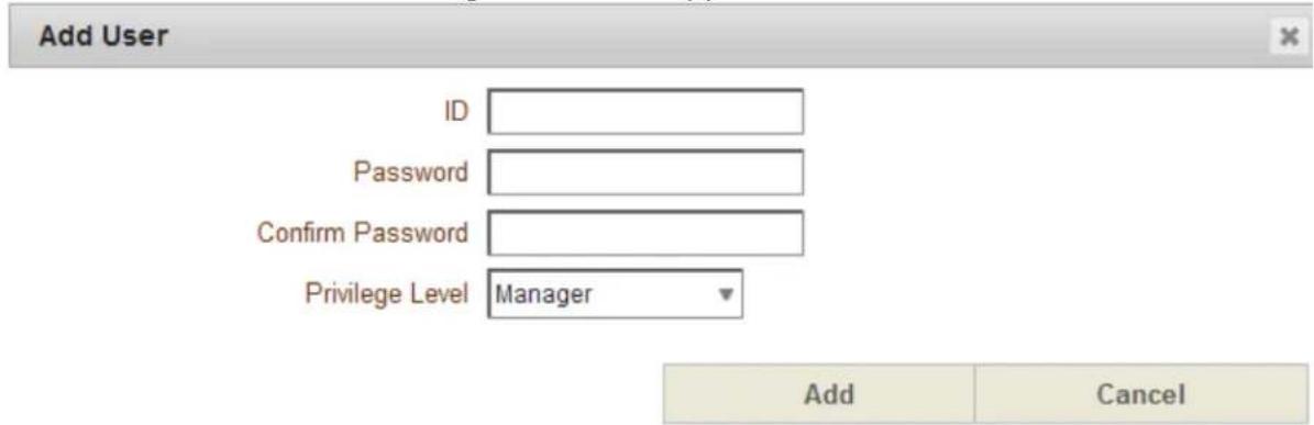
Enter User ID and password (Up to 15 characters) and select Privilege Level.
4. Remote Conguraon
- Delete User
Select the User to be deleted and press Delete button.
- Change Password
Press Modify Password button. The following window will appear.
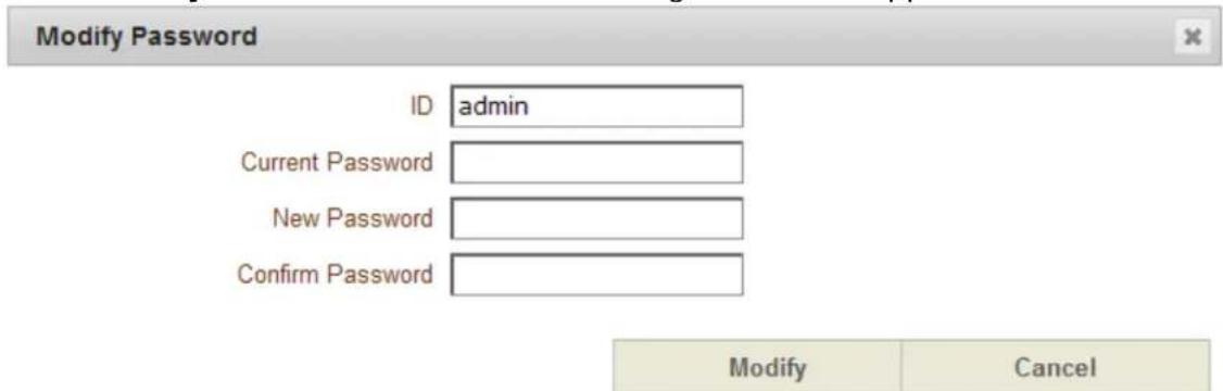
Enter the current password and then set a new password.
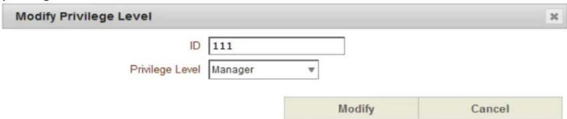
- Modify Privilege Level
Press Modify Privilege button to change User level. It is not allowed to change the privilege level of admin user.
4. Remote Conguraon
Login Policy
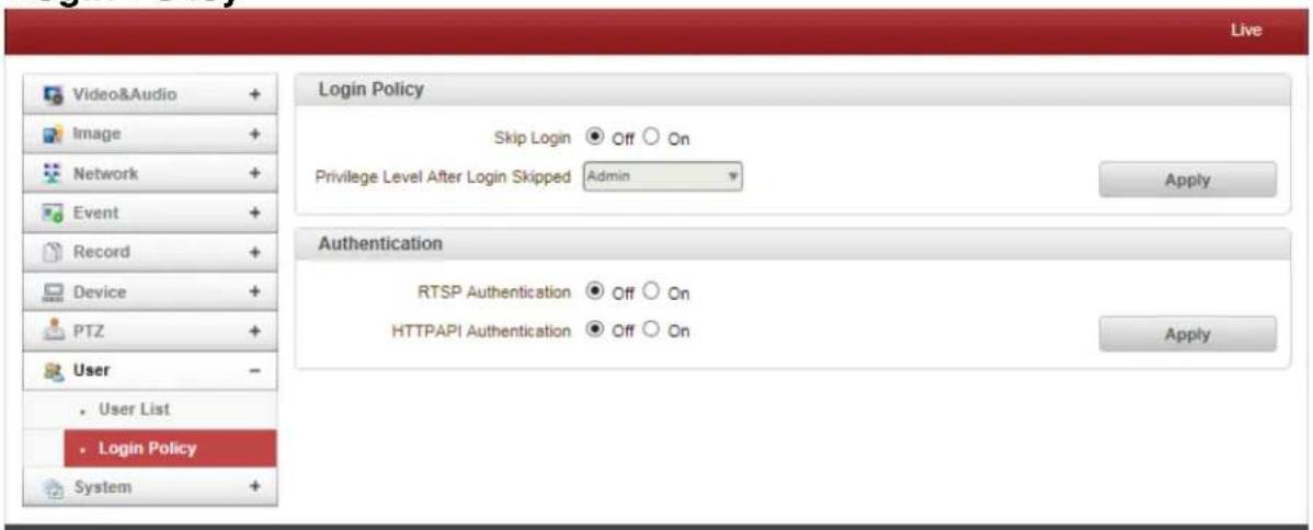
- Login Policy
Skip Login provides for convenient access to the server when authentication is not required. When Skip Login is set to Enable, login step is skipped. The privilege level after login in this way is determined by the setting of Privilege Level After Login Skipped.
- Authentication
HTTP authentication based on RFC 2617(HTTP Authentication: Basic and Digest Access Authentication) is supported.
4. Remote Conguraon
4.10 System Configuration
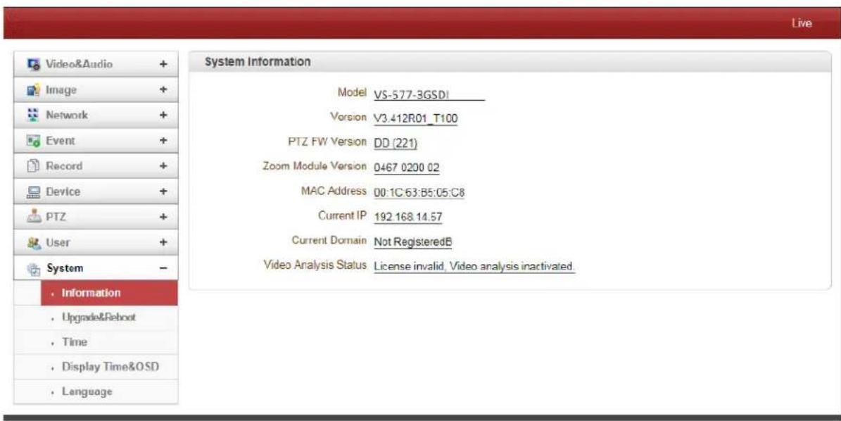
- System information
This following Network Information is displayed (Read Only):
- Model
Display the model name.
- Version
Display the current firmware version.
- Mac Address
Display the MAC address of the server. In case the IP Camera is registered at DDNS Server, the MAC address is used in DDNS registration.
- Set Current Time
Display Current Date and Time
- Current Domain
In case the Server is registered at DDNS Server, the registered domain name is displayed.
4. Remote Conguraon
Upgrade & Reboot
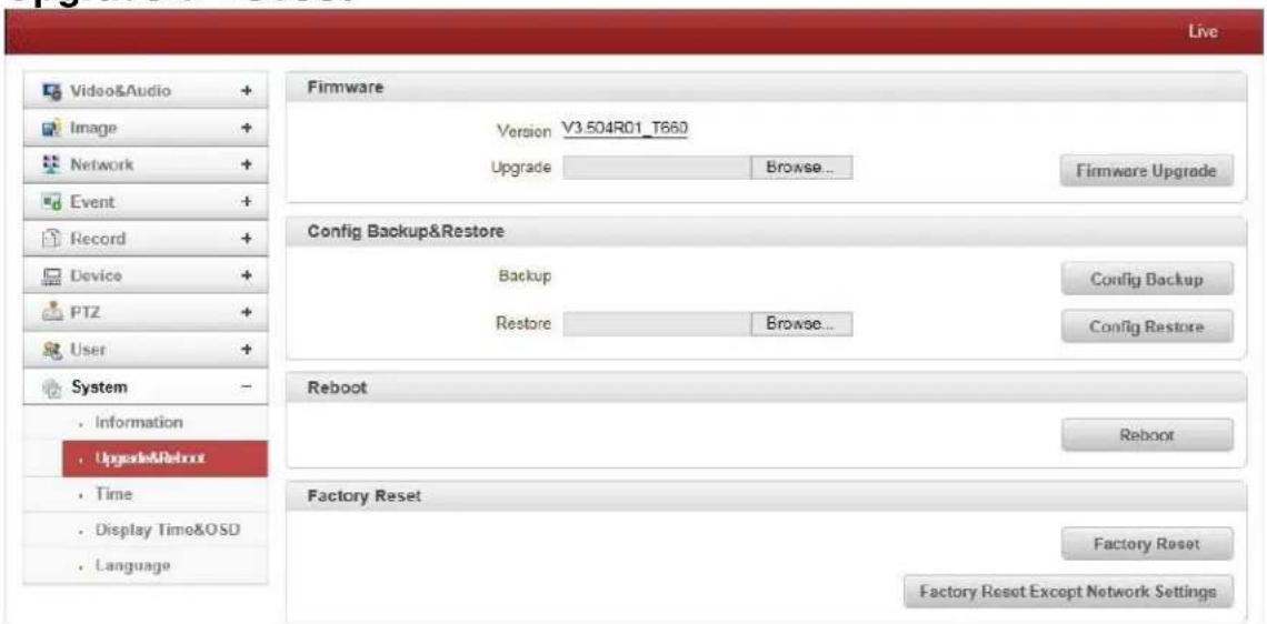
- Firmware
- Version: Displays the current firmware version.
-
Upgrade: Complete the following to upgrade the firmware:
-
Press Browse button to select a firmware file from PC.
- Press Firmware Upgrade button to start upgrading.
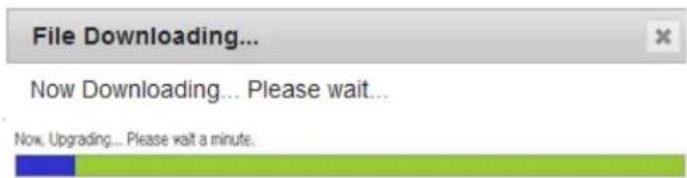
- A message for showing status (downloading / upgrading) will be displayed.
- The IP Camera will reboot automatically after completing upgrade.
Do not turn off the server during upgrading.
- Backup: All the setting of configuration can be stored.
- Restore: Stored configuration can be browsed and restored. The server is rebooted once the Config Restore button is selected.
- Reboot
- Reboot the Camera: Do not press the Reboot button unless the server needs a reboot.
- Factory Reset
All settings including user accounts and logs are cleared.
• Factory Reset Except Network Settings
All settings except for current network settings are changed to the default values.
4. Remote Conguraon
Time
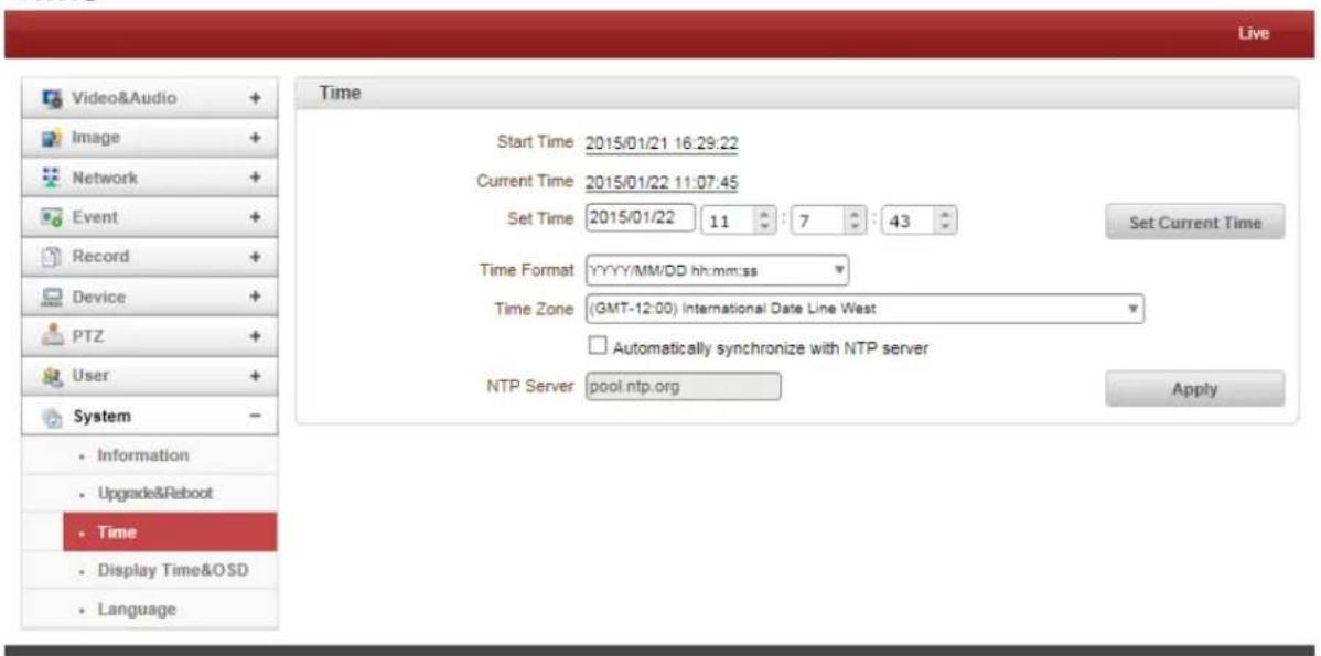
- Start Time
The latest server's booting date and time.
- Current Time
Current date and time.
Enter a new date and time then press Set Current Time button to update date & time.
- Time Format
Change the time format. The selectable time formats are as below;
- YYYY/MM/DD hh:mm:ss (Eg. 2012/10.30 12:30:45)
- DD/MM/YYYY hh:mm:ss (Eg. 10/30/2012 12:30:45)
- MM/DD/YYYY hh:mm:ss (Eg. 30/10/2012 12:30:45)
- Time Zone
Select time zone of where the server is installed. Depending on the time zone, Daylight Saving Time will work automatically.
A Time Zone is a region of the earth that has uniform standard time, usually referred to as the Local Time. By convention, time zones compute their local time as an offset from UTC (Coordinated Universal Time). In casual use, GMT (Greenwich Mean Time) can be considered equivalent to UTC. Local time is UTC plus the current time zone offset for the considered location
4. Remote Conguraon
• Automatic Synchronize with NTP Server
Synchronize the server time with an NTP Server using NTP (Network Time Protocol). Name of the NTP Server should be registered on NTP Server Name.
The Network Time Protocol (NTP) is a protocol for synchronizing the clocks of computer systems over packet-switched, variable-latency data networks. It is designed particularly to resist the effects of variable latency by using a jitter buffer.
Display Time & OSD
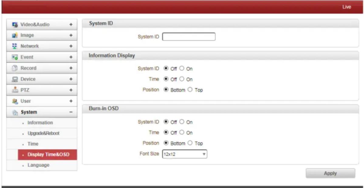
- System ID
Enter System ID that is used for this camera.
The set System ID is displayed with video image on a Web Browser. The System ID is also transferred to remote software, such as VMS, and displayed on it.
- Information Display
System ID and/or IP Camera time can be displayed over the video window in Internet Explorer. Each item can be turn on or off separately, and position also can be configured. This information is displayed after the video is decompressed.
- Burn In OSD
Insert System ID and date/time in the compressed video. System ID and time respectively can be turned on or off in the video. Position and Font size can be configured also. System ID for BurnIn OSD exists independently from normal System ID.
4. Remote Conguraon
Note: the size of Burnin OSD display varies according to the encoding resolution setting. This is inevitable because Burnin OSD is inserted to the frames before encoding is performed. The following table describes the rule for BurnIn OSD display.
| Resolution | Small (8x8) | Middle (16x16) | Large (32x32) |
| 352x480 / 352x240 / 352x576 / 352x288 | 2 | 1 | 0 |
| 720x480 / 720x240 / 720x576 / 720x288 / 640x480 / 800x600 | 2 | 2 | 1 |
| 1024 x 768 / 1280x720 / 1280 x 960 / 1280x1024 / 1440x900 / 1600x900 / 1680x1050 / 1920x1056 / 1920x1080 / 2048x1536 / 2560x1600 / 2592x1936 | 2 | 2 | 2 |
• 2: Both System ID and Time are displayed.
• 1: Either System ID or Time can be displayed. When both are enabled, System ID is displayed.
- 0: No items are displayed. This is because video area is too small to display OSD text in large text.
Language
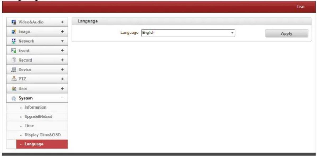
- Language
Select the Language to be used for Web-Based Configuration.
5. VS Manager
VS Manager is a program used for basic configuration, diagnostics and firmware upgrade of video servers or IP servers. VS Manager provides the following features:
• Finding servers on the LAN and assigning IP Addresses.
• Monitoring Server Status: Encoding/Decoding, Serial, Sensor, etc.
- Diagnostic Function: PING, Network Bandwidth Measurement, Video/Audio Output, Port Check, Serial Port Check.
- Firmware Upgrade.
VS Manager Software Download:
http://www.lcdracks.com/servers-cameras/software/software.php
- Create a folder on your 'C' drive and download the file into that folder using the link above.
- Copy and paste the link above into an Internet Explorer address window.
- Right mouse click on the file and make a shortcut on your desktop (using "send to command")
- Launch the application by double clicking on the desktop icon.
- Login = admin, Password = 1234.
For Windows 7, 64 bit ONLY:
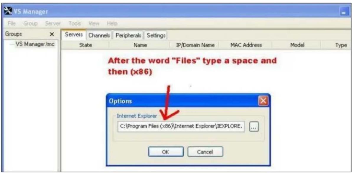
Once VS Manager installed, select IP Discovery, create servers.
On main page go to Tools, Options and change to this path below.
In the address window, after the word "Files" type a space then (x86).
VS-577-3GSDI
30x Zoom Hybrid Broadcast / IPTV PTZ Dome Camera
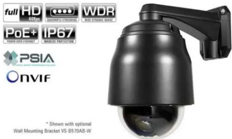
• 1/2.8-inch Progressive Scan CMOS
• 2.0 MP 30X Optical Zoom, 12X Digital Zoom
• Supports up to 1080p/59.94 or 1080i/59.94
- 1 x Video Out
• 3GSDI Model supports Low Latency Live Video Out
• Quad H.264 Streams Out
• True Day & Night (ICR)
• Camera Matches Photometrically with the VS-547
- Two Way Audio in Stereo
• Max Stream Out: 1920x1080 at 60FPS
• True Flickerless WDR (Wide Dynamic Range)
- Micro SD Card Recording
- Motion Detection for Instant Alarm & Recording
- Fast & Smooth Motion with 360^ Pan Rotation (continuous)
• RS-485 Serial Control supporting Pelco D or Pelco P Protocol
• Auto Parking / Power Up Action Function
• Dual Power Options of 12V DC or PoE+ (802at)
• ONVIF, PSIA Compliant
- Models available for 3GSDI Output or CVBS Output
- Adjustable Video Bitrate: 32Kbps\~16Mbps for Primary Video, 32Kbps \~ 4Mbps for Secondary Video Streams
- Various protocols supported: TCP/IP, Multicast, UDP, HTTP, SMTP & FTP DHCP, DNS, Dynamic DNS, RTP, RTSP, SNMP
natural_image
Black rectangular electronic device with attached cables and a small connector (no visible text or symbols)INCLUDES POWER SUPPLY*
*required for applications not utilizing PoE
6. Data Sheet
Specification Sheet
| VS-577A-3GSDI Specifications | ||
| Network | Network Interface | Ethernet 10/100base-T (R)-45) |
| Network Protocol | IPv4/v6, TCP, UDP, IGMP(Multicast),DHCP, HTTP, HTTPS, RTP, RTSP, FTP, SNMP, SMTP, UPnP, WS- Discovery, Zero Configuration, DDNS | |
| Security | Password protection, IP address filtering, HTTPS encryption | |
| API | MEI Protocol, SDK, ONVIF, PSIA, MPEG-TS | |
| Camera | Image Sensor | 1/2.8" Exmor CMOS |
| Focal Length | F=4.9 - 129mm | |
| Zoom | Optical x30 Digital x12 | |
| Maximum aperture ratio | F1.6 - F4.7 | |
| Angle of View | Horizontal: 63.7"(wide) - 2.3"(tele) | |
| Minimum Illuminance | Normal: 1.4Lux(color), 0.19Lux(B/W, ICR Off) with 50IREHigh Sensitivity: 0.013Lux(color), 0.002Lux(B/W ICR On) with 50IRE | |
| Electronic shutter speed | 1/1 - 1/10,000 sec | |
| Privacy masking | 8 regions | |
| Flip mode | Horizontal, Vertical | |
| Image enhancement | AE, AWB, AGC, TDN, DNR, BLC, WDR, DSS, Defog, Color Enhancement | |
| Video | Compression | H.264, MJPEG |
| Bitrate | Primary: 32Kbps - 16Mbps, Secondary x3: 32Kbps - 4Mbps | |
| Resolutions | 352x240 - 1920x1080 | |
| Frame Rate | Max 60fps @ 1920x1080 | |
| Output | Direct 3G-SDI live view | |
| Streaming | Primary: H.264, Secondary x 3: H.264/MJPEG | |
| Burn-in OSD | Multi-lingual | |
| Output | 3GSDI - Low Latency Live Output | |
| Audio | Compression | G.711 / AAC |
| Sample Rate | G.711: 8 KHz, AAC : 32 kHz / 44,1 kHz / 48 kHz | |
| Bitrate | G.711: 64Kbps, AAC: 64Kbps/128Kbps | |
| Streaming | G.711: Full-duplex, AAC: Half-duplex | |
| Input / Output | 1 x Line-In (stereo, RCA type), 1 x Line-Out (stereo, RCA type) | |
| Event | Event sources | Motion, Sensor input, Client disconnection |
| Event actions | Notification (E-mail), FTP, PTZ preset, Alarm control, Recording | |
| General | Housing | IP67 |
| Certifications | CE, FCC, KC, RoHS | |
| External devices | 2 x Sensor-In (dry contact, NO/NC)2 x Alarm-Out (dry contact, NO)1 x RS-48S port: Direct PTZ control etc | |
| Edge storage | Micro SD | |
| Power supply | Min 12V/3A, Min 24V//3.5A, PoE+ (Power over Ethernet): 802.3at | |
| Power consumption | DC12V/PoE+: Max 30W, AC24V: Max 48W | |
| Operating Temperature | -10°C - 50°C (14°F - 122°F) / 20% - 80% RH | |
| Dimension | Dome: ∅148 mm/ Å~ 5.8" | |
| Weight | 3,020g (Housing Net: 3,440g) | |
Appendix A: Sensor and Alarm Port
Sensor Port
- Terminal Type
- Voltage Rating: 150VAC
- Current Rating : 2A
- Color : Red
- Sensor Signal Input Type
- NO Contact Signals
- Connection to External Device
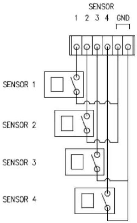
Alarm Port
- Terminal Type
- Voltage Rating: 150VAC
- Current Rating : 2A
- Relay Type
- Contact Rating : 1A 30VDC
- Switching Power : Max 30W 62.5VA
- Switching Voltage : Max 60VDC
• Alarm Signal Output Type
- NO/NC Contact Signals
- Connection to External Device
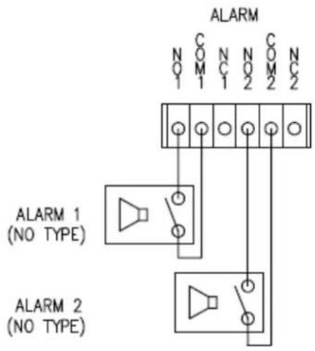
7. Appendix
Appendix B: Serial Port
RS-232 Port
- Terminal Type
- 3 PIN
- Pin Arrangement


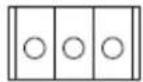
RS-232
Pin Description:
| Pin NO | Pin Name | Description |
| 1 | TX | RS232 TX(Transmit) |
| 2 | RX | RS232 RX(Receive) |
| 3 | GND | Ground |
RS-422/485 Port
- Port Type
- 4 PIN
- Pin Diagram
RS-422/485 TERMINALS
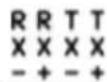
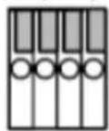
Pin Description:
| Pin No. | Pin Name | Description |
| 1 | RX- | RS422 RX- |
| 2 | RX+ | RS422 RX+ |
| 3 | TX- | RS422 TX- or RS485 TRX-It is selectable by S/W Setup |
| 4 | TX+ | RS422 TX+ or RS485 TRX+It is selectable by S/W Setup |
Marshall Electronics, Inc.
1910 East Maple Ave. El Segundo, CA 90245
Tel: (800) 800-6608 / (310) 333-0606 • Fax (310) 333-0688
www.LCDRacks.com • sales@lcdracks.com
- Marshall Electronics
- VS-577A-3GSDI
- Megapixel IP PTZ Camera
- 30x Zoom CMOS
- User Manual
- Trademarks
- Disclaimer
- Safety Precaution
- Introduction......4
- Installation......8
- System Operation....10
- Remote Configuration....13
- VS Manager 69
- Data Sheet 70
- Appendix ......72
- Introducon
- About this Manual
- Features
- Video
- Audio
- Network
- Serial Data
- Sensor and Alarm
- User Interface
- High Reliability
- Powerful Pan/Tilt Functions
- Preset, Pattern, Swing, Group
- PTZ (Pan/Tilt/Zoom) Control
- Easy Installation and Perfect Outdoor Environment Compatibility
- System Connections
- Topology
- Multicast Mode
- - Relay
- • VMS (Video Management System)
- Connecting Power
- Connecting Network
- Connecting Video
- Connecting Audio
- Connecting Serial Port (RS-485 Communication)
- Connecting Sensor and Alarm
- Installaon
- Check If It Works
- System Operaon
- Remote Video Monitoring
- Video Monitoring using Internet Explorer
- - Video Select
- - View Size
- - Digital Zoom
- • PTZ Control (Optical Zoom & Digital Zoom Built-In Camera)
- - Select Preset
- • Sensor Input and Alarm Input
- - Snapshot
- - Talk
- - File Record
- - Display Buffer
- Video Monitoring with Decoder System
- Initialization of IP address
- Remote Conguraon
- System Configuration
- Video & Audio Configuration Information
- - Performance Calculation
- - Input Format
- - Resolution
- - Framerate
- - Preference
- - Quality
- - Bitrate
- - I-Frame Interval
- - H.264 Profile
- High Profile
- Baseline Profile
- - Use Dual Encode
- - ROI Encoding (Region of Interest)
- - Algorithm
- - Mode
- - Input Gain
- - Output Format
- - Audio
- Image Configuration
- Day & Night
- White Balance
- Auto Exposure
- - DSS Mode
- ● Back Light Compensation
- - Gamma Mode
- Auto Focus
- ● Minimum Focus Length
- - AF Sensitivity
- - Focus Offset
- Enhancement
- WDR
- - Noise Reduction
- - Stabilizer Mode
- - Defog Mode
- - Aperture Control
- - Color Gain
- ● High Sensitivity
- Other
- - Image Flip
- - Mirror
- - Chroma Suppress
- Codec
- - Brightness
- - Contrast
- - Saturation
- - Noise Filter
- - Edge Enhancement
- - Edge Enhancement Sensitivity
- ● Edge Enhancement Strength
- Schedule
- - Configuration Set
- - Scheduling Configurations
- Mask
- Network IP & Port Configuration
- DNS
- IPv6
- Port
- - Multicast
- • UPNP
- - Zeroconf
- - WS Discovery
- - DynDNS
- • Vdyn
- - Check IP Disable
- - Server Address
- - Port
- - Sender Address
- • Authentication on SMTP Server
- - ID & Password
- - Destination Address
- - Email Test
- Email Notification
- • Video Clip Attaching
- - Capture Interval
- • ID & Password
- - FTP File Name
- - FTP Base Directory
- - FTP Test
- FTP Upload
- - Upload Video
- • Number of Frame
- • Continuous Upload
- - Upload Duration
- - Upload Interval
- - Google Drive Auth
- - Base Directory
- • Number of Frames
- Event Configuration
- - Local Event Configuration
- - Local & Remote Event Configuration
- - Sensor1 / Sensor2
- - On Video Loss
- - On Motion
- - On Disconnect
- - Motion Detection Area Editing
- Audio Detection
- - Silence Detection
- - Sound Detection
- - Sensor Type
- - Sensor Schedule
- Video Analytics
- General
- - Sensitivity
- - Color Check
- - Tracker Type
- - Object Enable / Object Width / Object Height
- ● People Enable / People Width / People Height
- ● Vehicle Enable / Vehicle Width / Vehicle Height
- Line Crossing
- - Camera Height
- Intrusion
- - Object Size
- Tampering
- Record Configuration
- - Use Record
- - Select Video
- - Manual Record
- - Overwrite
- • Max File Size / Max File Length
- • Automatically Backup to FTP
- - Erase After Backup
- - Start Time of Backup Data
- Checking Status of Recording
- - Event Type
- - Schedule Table
- - Playback
- Device Configuration
- - Serial Protocol:
- - Serial Port Configuration:
- PTZ Configuration
- - PTZ Type
- - PTZ ID
- - PTZ Port
- A max of 128 preset positions can be defined.
- Swing
- Advanced
- Auto Parking
- User Configuration
- - Add User
- - Delete User
- - Change Password
- - Modify Privilege Level
- - Login Policy
- - Authentication
- System Configuration
- - System information
- - Firmware
- - Reboot
- - Factory Reset
- • Factory Reset Except Network Settings
- - Start Time
- - Current Time
- - Time Format
- - Time Zone
- • Automatic Synchronize with NTP Server
- - System ID
- - Information Display
- - Burn In OSD
- - Language
- VS Manager
- VS Manager Software Download:
- For Windows 7, 64 bit ONLY:
- Data Sheet
- Appendix A: Sensor and Alarm Port
- Sensor Port
- Alarm Port
- Appendix
- Appendix B: Serial Port
- RS-232 Port
- RS-422/485 Port
- Marshall Electronics, Inc.
Brand : MARSHALL
Model : VS-577A-3GSDI
Category : Security Camera