WAP-PC1750W - Access Point Comtrend - Free user manual and instructions
Find the device manual for free WAP-PC1750W Comtrend in PDF.


| Product Type | Wireless Access Point |
| Brand | Comtrend |
| Model | WAP-PC1750W |
| Wireless Standard | IEEE 802.11ac (WiFi 5) |
| Frequency Bands | Dual-band (2.4 GHz + 5 GHz) |
| Maximum Data Rate | Up to 1750 Mbps (450 Mbps on 2.4 GHz + 1300 Mbps on 5 GHz) |
| Ethernet Ports | 1x Gigabit Ethernet (10/100/1000) with PoE support |
| Power Supply | PoE (802.3af/at) or DC 12V 1A (adapter included) |
| Dimensions (HxWxD) | Approx. 30 x 160 x 160 mm |
| Weight | Approx. 250 g |
| Wireless Security | WPA2-PSK/WPA3-PSK, WEP, MAC filtering |
| Management | Web interface (HTTP/HTTPS), SNMP, CLI (SSH/telnet) |
| Mounting | Wall-mountable (bracket included) or desktop placement |
| LED Indicators | Power, LAN, Wireless (2.4G/5G) |
| Operating Temperature | 0°C to 40°C (32°F to 104°F) |
| Operating Humidity | 10% to 90% (non-condensing) |
| Antenna | 4x internal dual-band antennas |
| Warranty | 1 year limited warranty |
| Package Contents | Access point, power adapter, mounting bracket, screws, Ethernet cable, quick start guide |
| Maintenance | Clean with dry cloth; avoid liquids and direct sunlight |
| Compliance | FCC, CE, RoHS |
Frequently Asked Questions - WAP-PC1750W Comtrend
User questions about WAP-PC1750W Comtrend
0 question about this device. Answer the ones you know or ask your own.
Ask a new question about this device
Download the instructions for your Access Point in PDF format for free! Find your manual WAP-PC1750W - Comtrend and take your electronic device back in hand. On this page are published all the documents necessary for the use of your device. WAP-PC1750W by Comtrend.
USER MANUAL WAP-PC1750W Comtrend
Version 1.0, January 2015
natural_image
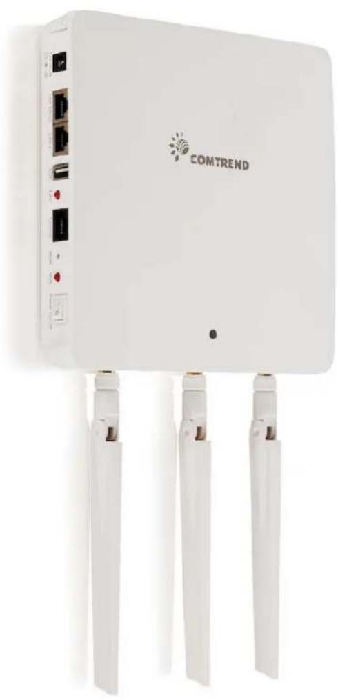
White COMTREND wireless router with three Ethernet ports and ventilation slots (no visible text or symbols on the device body)FCC Compliance
This equipment has been tested and found to comply with the limits for a Class B Digital Device, pursuant to part 15 of the FCC Rules. These limits are designed to provide reasonable protecon against harmful interference in a residential installaon. This equipment generates, uses and can radiate radio frequency energy and, if not installed and used in accordance with the instrucon, may cause harmful interference to radio communicaon. However, there is no guarantee that interference will not occur in a parcular installaon. If this equipment does cause harmful interference to radio or television reception, which can be determined by turning the equipment o and on, the user is encouraged to try to correct the interference by one or more of the following measures:
- Reorient or relocate the receiving antenna
- Increase the separaon between the equipment and receiver
- Connect the equipment into an outlet on a circuit dierent from that to which the receiver is connected
- Consult the dealer or an experienced radio/TV technician for help.
The changes or modicaons not expressly approved by the party responsible for compliance could void the user's authority to operate the equipment.
To comply with the FCC RF exposure compliance requirements, this device and its antenna must not be co-located or operang to conjuncon with any other antenna or transmier.
This equipment should be installed and operated with minimum distance 20cm between the radiator & your body.
Copyright
Copyright© 2015 Comtrend Corporaon. All rights reserved. The informaon contained herein is proprietary to Comtrend Corporaon. No part of this document may be translated, transcribed, reproduced, in any form, or by any means without the prior written consent of Comtrend Corporaon.
This program is free soware: you can redistribute it and/or modify it under the terms of the GNU General Public License as published by the Free Soware Foundaon, either version 3 of the License, or (at your opon) any later version.
This program is distributed in the hope that it will be useful, but WITHOUT ANY WARRANTY; without even the implied warranty of MERCHANTABILITY or FITNESS FOR A PARTICULAR PURPOSE. See the GNU General Public License for more details.
You should have received a copy of the GNU General Public License along with this program. If not, see hp://www.gnu.org/licenses/
NOTE: This document is subject to change without noce.

This symbol indicates that when the equipment has reached the end of It's useful life, it must be taken to a recycling centre and processed separate from domesc
The cardboard box, the plasc contained in the packaging, and the parts that make up this router can be recycled in accordance with regionally established regulaons. Never dispose of this electronic equipment along with your household waste; you may be subject to penales or sancons under the law. Instead, please be responsible and ask for disposal instrucons from your local
CONTENTS
I. Product Informaon....6
I-1. Package Contents ....6
I-2. System Requirements....7
I-3. Hardware Overview....7
I-4. LED Status 8
I-5. Reset 8
I-6. Magnec Wall Mount....9
I-7. Safety Informaon....10
II. Quick Setup 11
II-1. Inial Setup....11
II-2. Basic Sengs ....13
II-3. Wi-Fi Protected Setup (WPS)....17
III. Hardware Installaon.... 18
IV. Browser Based Conguraon Interface.... 19
IV-1. Informaon....21
IV-1-1. System Informaon 21
IV-1-2. Wireless Clients....25
IV-1-3. Wireless Monitor 27
IV-1-4. Log....29
IV-2. Network Sengs 31
IV-2-1. LAN-Side IP Address....31
IV-2-2. LAN Port 33
IV-2-3. VLAN....34
IV-3. Wireless Sengs....35
IV-3-1. 2.4GHz 11bgn....35
IV-3-1-1. Basic 36
IV-3-1-2. Advanced 39
IV-3-1-3. Security 41
IV-3-1-3-1. No Authencaon ....42
IV-3-1-3-2. WEP....43
IV-3-1-3-3. IEEE802.1x/EAP 43
IV-3-1-3-4. WPA-PSK 43
IV-3-1-3-5. WPA-EAP 44
IV-3-1-3-6. Additional Authencaon 44
IV-3-1-4. WDS....46
IV-3-2. 5GHz 11ac 11an ....48
IV-3-2-1. Basic 48
IV-3-2-2. Advanced 51
IV-3-2-3. Security 53
IV-3-2-4. WDS....55
IV-3-3. WPS....57
IV-3-4. RADIUS....59
IV-3-4-1. RADIUS Sengs 60
IV-3-4-2. Internal Server 62
IV-3-4-3. RADIUS Accounts 64
IV-3-5. MAC Filter 66
IV-3-6. WMM....68
IV-4. Management 70
IV-4-1. Admin....70
IV-4-2. Date and Time....73
IV-4-3. Syslog Server....75
IV-4-4. I'm Here 76
IV-5. Advanced 77
IV-5-1. LED Sengs 77
IV-5-2. Update Firmware....78
IV-5-3. Save/Restore Sengs....79
IV-5-4. Factory Default 81
IV-5-5. Reboot....82
V. Appendix 83
V-1. Conguring your IP address....83
V-1-1. Windows XP 84
V-1-2. Windows Vista 86
V-1-3. Windows 7....88
V-1-4. Windows 8....92
IV-1-5. Mac 96
V-1-6. Glossary....98
I. Product Informaon
I-1. Package Contents
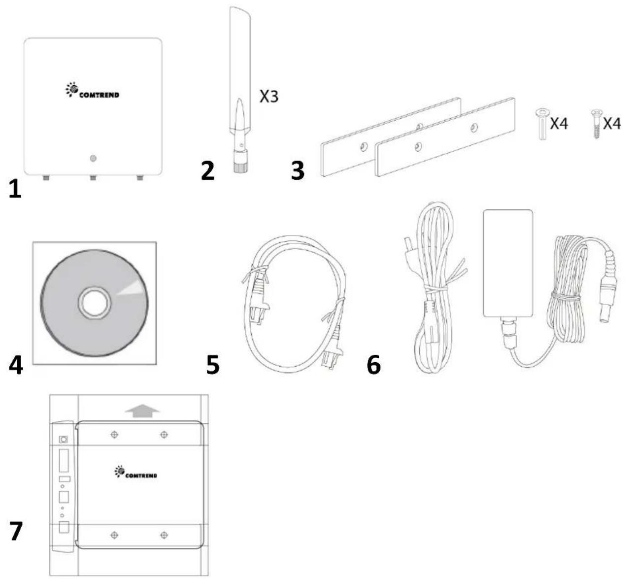
- WAP-PC1750W Access Point
- Antennas x 3
- Magnec Wall Mount x 2 & Screws
-
CD
-
Ethernet Cable
- Power Adapter
- Magnec Wall Mount Screw Template
I-2. System Requirements
- Exisng cable/DSL modem & router
- Computer with web browser for access point conguraon
I-3. Hardware Overview
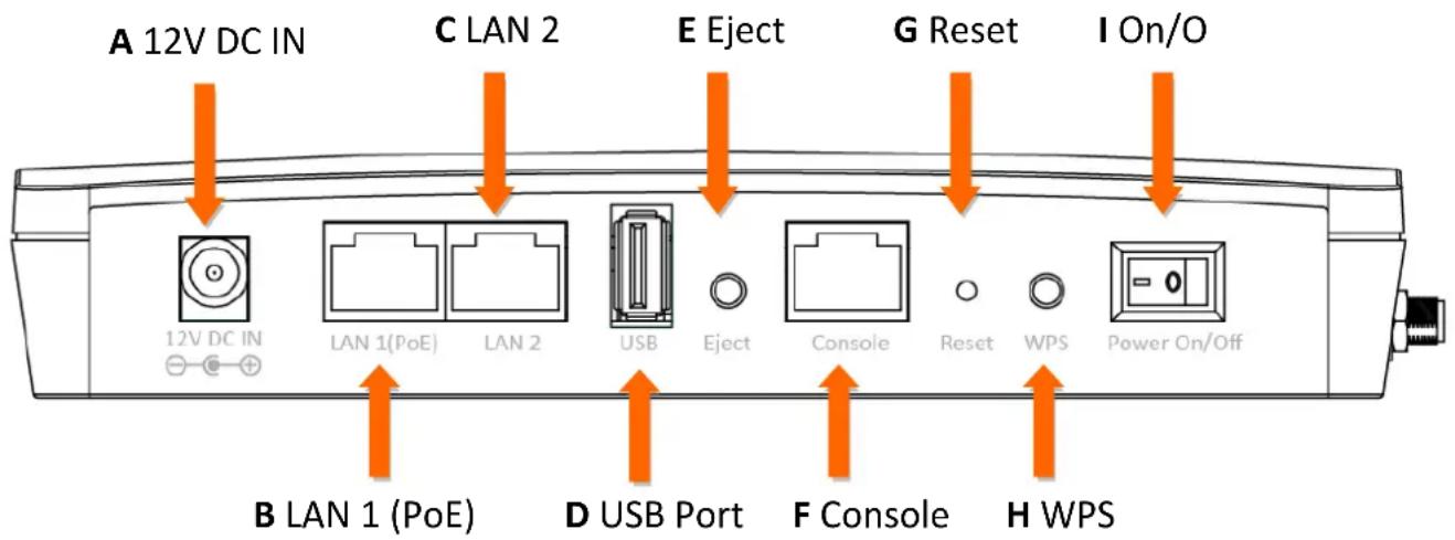
A. 12V DC port to connect the power adapter
B. LAN port with Power over Ethernet (PoE) IN
C. LAN port with Power over Ethernet (PoE) OUT
D. USB Port for system log
E. Eject an aached USB device
F. Connect a management console
G. Reset the access point to factory default sengs
H. Wi-Fi Protected Setup (WPS) buon
I. Switch the access point on/o
I-4. LED Status
| LED Status | Descripon |
| O | The access point is o. |
| Blue | The access point is on. |
| Amber | The access point is starng up. |
| Flashing Amber | The access point cannot establish a conneccon to the network. |
| Flashing Amber and Blue | The access point experienced a problem starng up. The access point will restart. |
I-5. Reset
If you experience problems with your access point, you can reset the device back to its factory sengs. This resets all sengs back to default.
- Press and hold the reset buon on the access point for at least 10 seconds. Release the buon when the LED is ashing AMBER.

You may need to use a pencil or similar sharp object to push the reset buon.
- Wait for the access point to restart. The access point is ready for setup when the LED is BLUE.
I-6. Magnec Wall Mount
The access point includes a magnec wall mount.
- Use the included magnec wall mount screw template to identify and mark correct screw posions on your selected wall.
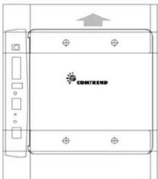
- Aach the two magnec wall mount strips to your wall using the included screws, as shown below.
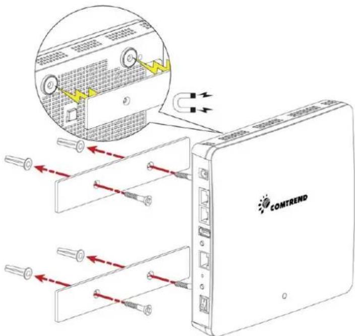
- Press the back of your access point rmly against the two wall mounted magnec strips, with the access point's Comtrend logo in the correct, upright orientaon as displayed above.

Ensure your access point is securely aached to the magnec strips.
I-7. Safety Informaon
In order to ensure the safe operaon of the device and its users, please read and act in accordance with the following safety instrucons.
- The access point is designed for indoor use only; do not place the access point outdoors.
- Do not place the access point in or near hot/humid places, such as a kitchen or bathroom.
- Do not pull any connected cable with force; carefully disconnect it from the access point.
- Handle the access point with care. Accidental damage will void the warranty of the access point.
- The device contains small parts which are a danger to small children under 3 years old. Please keep the access point out of reach of children.
- Do not place the access point on paper, cloth, or other ammable materials. The access point may become hot during use.
- There are no user-serviceable parts inside the access point. If you experience problems with the access point, please contact Comtrend Customer Service for assistance.
- The access point is an electrical device and as such, if it becomes wet for any reason, do not aempt to touch it without switching the power supply o. Contact an experienced electrical technician for further help.
- If you smell burning or see smoke coming from the access point or power adapter, then disconnect the access point and power adapter immediately, as far as it is safely possible to do so. Contact Comtrend Customer Service for assistance.
II-1. Inial Setup
-
Connect the access point to a computer via Ethernet cable.
-
Connect the power adapter to the access point's 12V DC port and plug the power adapter into a power supply.
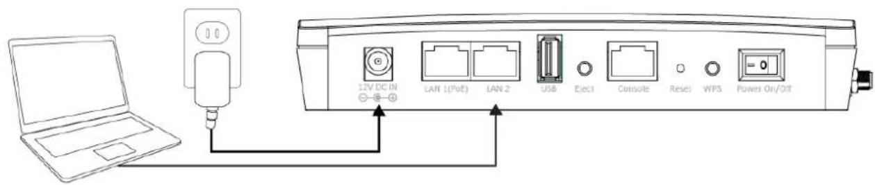
-
Please wait a moment for the access point to start up. The access point is ready when the LED is blue.
-
Set your computer's IP address to 192.168.2.x where x is a number in the range 3 – 100. If you are unsure how to do this, please refer to Appendix V-1. Conguring your IP address for more informaon.

Please ensure there are no other acve network connecons on your computer (disconnect Wi-Fi connecons and Ethernet cables).
- Enter the access point's default IP address 192.168.2.2 into the URL bar of a web browser.

- You will be prompted for a username and password. Enter the default username "admin" and the default password "1234".
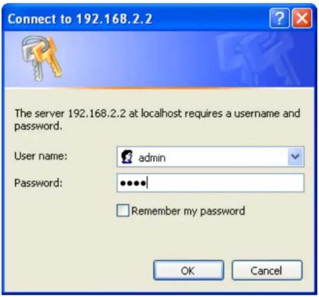
- You will arrive at the "System Informaon" screen shown below.
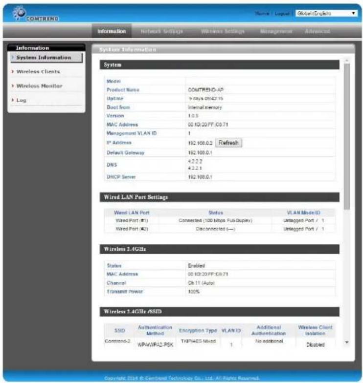
- Next, please follow the instrucons below in II-2. Basic Sengs to conjure the access point's basic sengs.

For more advanced conguraons, please refer to IV. Browser Based Conguraon Interface.
II-2. Basic Sengs
The instrucons below will help you to congregate the following basic sengs of the access point:
- LAN IP Address
- 2.4GHz & 5GHz SSID & Security
- Administrator Name & Password
- Time & Date

It is recommended you congregate these sengs before using the access point.
- To change the access point's LAN IP address, go to "Network Sengs" > "LAN-side IP Address" and you will see the screen below.
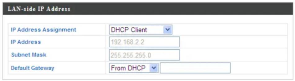

- Enter the IP address sengs you wish to use for your access point. You can use a dynamic (DHCP) or stac IP address, depending on your network environment. Click “Apply” to save the changes and wait a few moments for the access point to reload.

When you change your access point's IP address, you need to use the new IP address to access the browser based conguraon interface instead of the default IP 192.168.2.2.
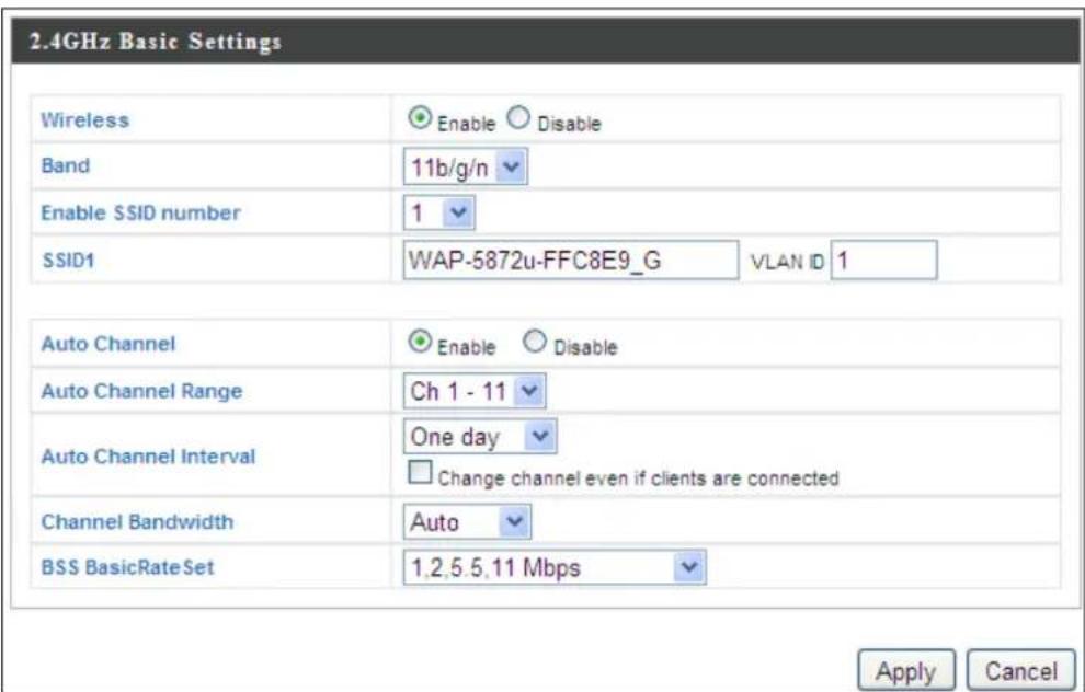
- To change the SSID of your access point's 2.4GHz wireless network(s), go to "Wireless Seng" > "2.4GHz 11bgn" > "Basic". Enter the new SSID for your 2.4GHz wireless network in the "SSID1" eld and click "Apply".

To ulize mulple 2.4GHz SSIDs, open the drop down menu labelled "Enable SSID number" and select how many SSIDs you require. Then enter a new SSID in the corresponding numbered elds below, before clicking "Apply".
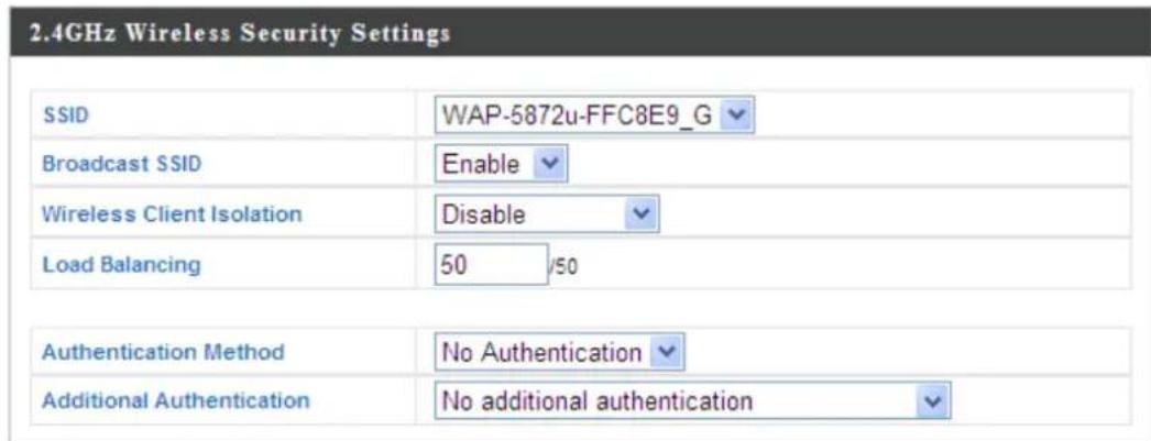
- To congregate the security of your access point's 2.4GHz wireless network(s), go to "Wireless Seng" > "2.4GHz 11bgn" > "Security". Select an "Authencaon Method" and enter a "Pre-shared Key" or "Encrypon Key" depending on your choice, then click "Apply".

If using mulple SSIDs, specify which SSID to congregate using the "SSID" drop down menu.
- Go to "Wireless Seng" > "5GHz 11ac 11an" and repeat steps 3 & 4 for the access point's 5GHz wireless network.
- To change the administrator name and password for the browser based conguraon interface, go to "Management" > "Admin".
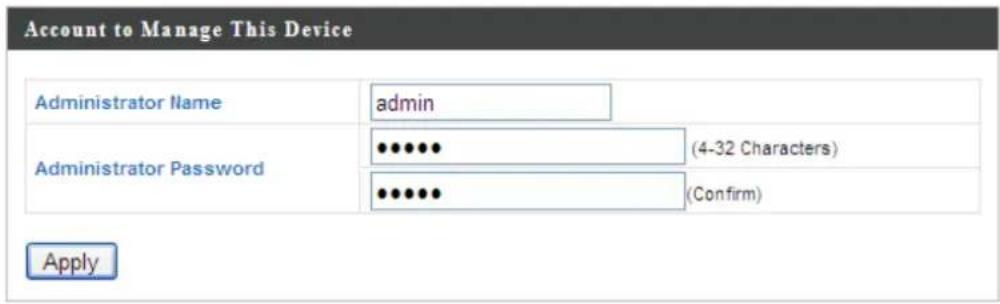
- Complete the "Administrator Name" and "Administrator Password" elds and click "Apply".
- To set the correct me for your access point, go to "Management" > "Date and Time".
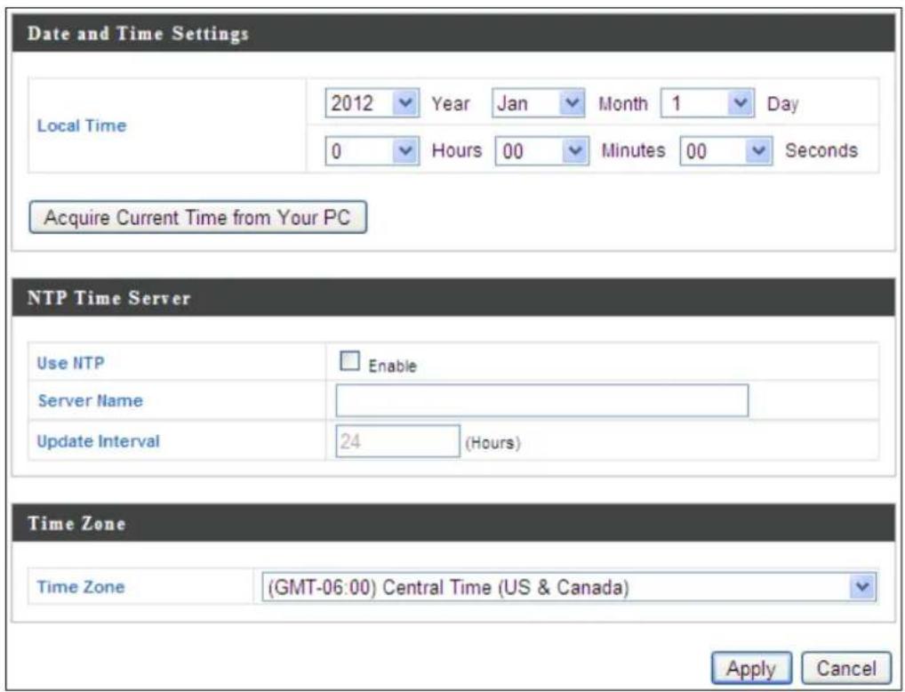
- Set the correct me and me zone for your access point using the drop down menus. The access point also supports NTP (Network Time Protocol) so alternatively you can enter the host name or IP address of a me server. Click “Apply” when you are nished.

You can use the "Acquire Current Time from your PC" buon if you wish to set the access point to the same me as your PC.
- The basic sengs of your access point are now congured. Please refer to III. Hardware Installaon for guidance on connecng your access point to a router or PoE switch.
II-3. Wi-Fi Protected Setup (WPS)
Wi-Fi Protected Setup is a simple way to establish connexons between WPS compatible devices. You can use the WPS buon to establish a connexon between the access point and a WPS-compatible wireless device/client.
- Press and hold the Reset buon on the front of the access point for 2 seconds.

- Within two minutes, activate WPS on your WPS-compatible wireless device. Please check the documentaon for your wireless device for informaon regarding its WPS funcon.
-
The devices will establish a conneccon.
-
Connect a router or switch to the access point's LAN 1 port using an Ethernet cable. If powering the access point by PoE, the PoE switches must be connected to the access point's LAN 1 port.
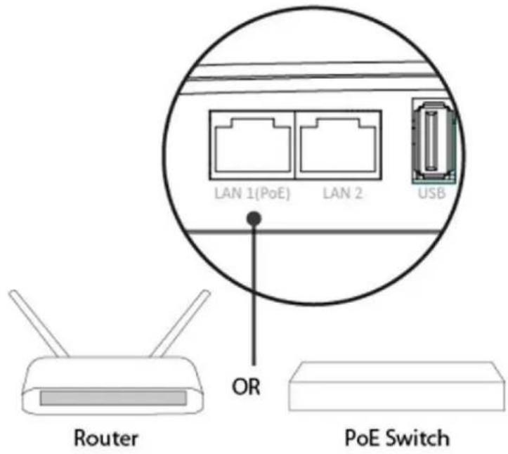
-
If you are not using a PoE switch, then connect the power adapter to the access point's 12V DC port and plug the power adapter into a power outlet.
-
If you are using a PoE (Power over Ethernet) switch then it is not necessary to use the included power adapter, the access point will be powered by the PoE switch.

Do not use the power adapter if you are using a PoE switch.
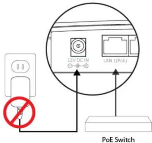
- (Oponal) Connect a local network device to the access point's LAN 2 port.

The access point's LAN 2 port can support PoE Power (IEEE 802.3af) if the access point is powered by the included 12v DC power adapter.
IV. Browser Based Conguraon Interface
The browser-based conguraon interface enables you to conjure the access point's advanced features. The WAP-PC1750W features a range of advanced funcons such as MAC Itering, MAC RADIUS authencaon, VLAN conguraons, up to 16 SSIDs and many more. To access the browser based conguraon interface:
- Connect a computer to your access point using an Ethernet cable.
- Enter your access point's IP address in the URL bar of a web browser. The access point's default IP address is 192.169.2.2
- You will be prompted for a username and password. The default username is “admin” and the default password is “1234”, though it was recommended that you change the password during setup (see II-2. Basic Sengs).

If you cannot remember your password, reset the access point back to its factory default sengs. Refer to secon 1-5. Reset
- You will arrive at the "System Informaon" screen shown below.
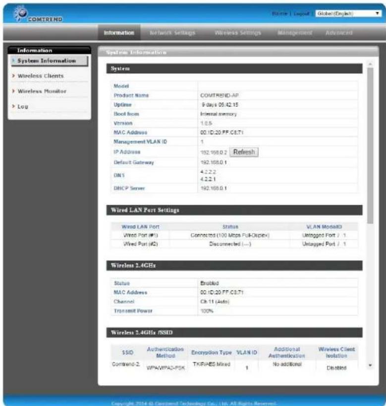
5. Use the menu across the top and down the le side to navigate.
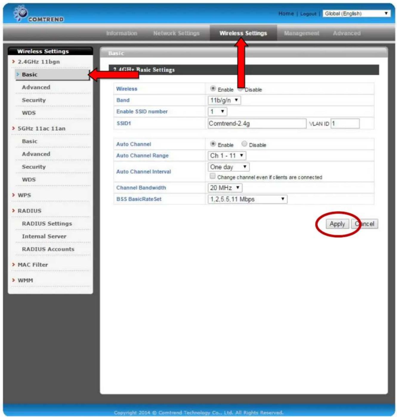
6. Click "Apply" to save changes and reload the access point, or "Cancel" to cancel changes.

Please wait a few seconds for the access point to reload aer you "Apply" changes, as shown below.
IV-1. Informaon
Information
Network Settings
Wireless Settings
Management
Advanced

Screenshots displayed are examples. The informaon shown on your screen will vary depending on your conguraon.
IV-1-1. System Informaon
System Information
The "System Informaon" page displays basic
system informaon about the access point.
System
| Model | |
| Product Name | COMTREND-AP |
| Uptime | 9 days 05:42:15 |
| Boot from | Internal memory |
| Version | 1.0.5 |
| MAC Address | 00:1D:20:FF:C8:71 |
| Management VLAN ID | 1 |
| IP Address | 192.168.0.2 Refresh |
| Default Gateway | 192.168.0.1 |
| DNS | 4.2.2.24.2.2.1 |
| DHCP Server | 192.168.0.1 |
Wired LAN Port Settings
| Wired LAN Port | Status | VLAN Mode/ID |
| Wired Port (#1) | Connected (1000 Mbps Full-Duplex) | Untagged Port / 1 |
| Wired Port (#2) | Disconnected (----) | Untagged Port / 1 |
Wireless 2.4GHz
| Status | Enabled |
| MAC Address | 00:1D:20:FF:C8:E9 |
| Channel | Ch 4 (Auto) |
| Transmit Power | 100% |
Wireless 2.4GHz /SSID
| SSID | Authentication Method | Encryption Type | VLAN ID | Additional Authentication | Wireless Client Isolation |
| WAP-5872u-FFC8E9_G | No Authentication | No Encryption | 1 | No additional authentication | Disabled |
Wireless 2.4GHz /WDS Disabled
| MAC Address | Encryption Type | VLAN Mode/ID |
| No WDS entries. | ||
Wireless 5GHz
| Status | Enabled |
| MAC Address | 00:1D:20:FF:C8:EA |
| Channel | Ch 36 + 40 + 44 + 48 (Auto) |
| Transmit Power | 100% |
Wireless 5GHz /SSID
| SSID | Authentication Method | Encryption Type | VLAN ID | Additional Authentication | Wireless Client Isolation |
| WAP-5872u-FFC8E9_A | No Authentication | No Encryption | 1 | No additional authentication | Disabled |
Wireless 5GHz /WDS Disabled
| MAC Address | Encryption Type | VLAN Mode/ID |
| No WDS entries. |
| Model | Displays the model number of the access point. |
| Product Name | Displays the product name for reference, which consists of “AP” plus the MAC address. |
| Upme | Displays the total me since the device was turned on. |
| Boot From | Displays informaon for the booted hardware, booted from either USB or internal memory. |
| Version | Displays the soware version of the access point. |
| MAC Address | Displays the access point's MAC address. |
| Management VLAN ID | Displays the management VLAN ID. |
| IP Address | Displays the IP address of this device. Click “Refresh” to update this value. |
| Default Gateway | Displays the IP address of the default gateway. |
| DNS | IP address of the DNS (Domain Name Server). |
| DHCP Server | IP address of the DHCP Server. |
| Wired LAN Port | Species which LAN port (1 or 2). |
| Status | Displays the status of the specied LAN port (connected or disconnected). |
| VLAN Mode/ID | Displays the VLAN mode (tagged or untagged) and VLAN ID for the specied LAN port. See IV-2-3. VLAN |
| Status | Displays the status of the 2.4GHz or 5GHz wireless (enabled or disabled). |
| MAC Address | Displays the access point's MAC address. |
| Channel | Displays the channel number the specied wireless frequency is using for broadcast. |
| Transmit Power | Displays the wireless radio transmit power level as a percentage. |
| SSID | Displays the SSID name(s) for the specied frequency. |
| Authencaon Method | Displays the authencaon method for the specied SSID. See IV-3. Wireless Sengs |
| Encrypon Type | Displays the encrypon type for the specied SSID. See IV-3. Wireless Sengs |
| VLAN ID | Displays the VLAN ID for the specied SSID. See IV-2-3. VLAN |
| Additional Authencaon | Displays the additional authencaon type for the specied SSID. See IV-3. Wireless Seings |
| Wireless Client Isolaon | Displays whether wireless client isolaon is in use for the specied SSID. See IV-2-3. VLAN |
| Refresh | Click to refresh all informaon. |
IV-1-2. Wireless Clients
> Wireless Clients
The "Wireless Clients" page displays informaon
about all wireless clients connected to the access point on the 2.4GHz or 5GHz frequency.

| # | SSID | MAC Address | Tx | Rx | Signal (%) | Connected Time | Idle Time | Vendor |
| No wireless client | ||||||||
| 5GHz WLAN Client Table | ||||||||
| # | SSID | MAC Address | Tx | Rx | Signal (%) | Connected Time | Idle Time | Vendor |
| No wireless client | ||||||||
| Auto Refresh Time | Select a me interval for the client table list to automacally refresh. |
| Manual Refresh | Click refresh to manually refresh the client table. |
| SSID | Displays the SSID which the client is connected to. |
| MAC Address | Displays the MAC address of the client. |
| Tx | Displays the total data packets transmied by the specied client. |
| Rx | Displays the total data packets received by the specied client. |
| Signal (%) | Displays the wireless signal strength for the specied client. |
| Connected Time | Displays the total me the wireless client has been connected to the access point. |
| Idle Time | Client idle me is the me for which the client has not transmied any data packets i.e. is idle. |
| Vendor | The vendor of the client’s wireless adapter is displayed here. |
IV-1-3. Wireless Monitor
> Wireless Monitor
Wireless Monitor is a tool built into the access point to
scan and monitor the surrounding wireless environment. Select a frequency and click “Scan” to display a list of all SSIDs within range along with relevant details for each SSID.
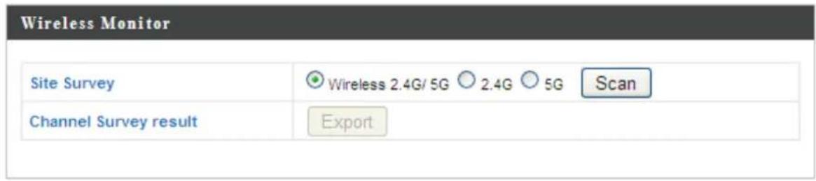


| Channel Survey | Select which frequency (or both) to scan, and click “Scan” to begin. |
| Channel Survey Result | Aer a scan is complete, click “Export” to save the results to local storage. |
| Ch | Displays the channel number used by the specied SSID. |
| SSID | Displays the SSID idened by the scan. |
| MAC Address | Displays the MAC address of the wireless router/access point for the specied SSID. |
| Security | Displays the authencaon/encrypon type of the specied SSID. |
| Signal (%) | Displays the current signal strength of the SSID. |
| Type | Displays the 802.11 wireless networking standard(s) of the specied SSID. |
| Vendor | Displays the vendor of the wireless router/access point for the specied SSID. |
IV-1-4. Log
Log
The system log displays system operaon informaon such as up me and conneccon processes. This informaon is useful for network administrators.

When the log is full, old entries are overwritten.
![Jan 1 00:01:18 [SYSTEM]: WLAN[2.4G], Best channel selection start, switch to channel 4 Jan 1 00:01:08 [SYSTEM]: WLAN[5G], Best channel selection start, switch to channel 36 + 40 + 44 + 48 Jan 1 00:00:17 [SYSTEM]: LAN, Port[1] link status is changed to down Jan 1 00:00:17 [SYSTEM]: LAN, Port[0] link is changed to 1000Mbps-Full-Duplex Jan 1 00:00:16 [SYSTEM]: HTTPS, start Jan 1 00:00:16 [SYSTEM]: HTTP, start Jan 1 00:00:16 [SYSTEM]: LAN, Firewall Disabled Jan 1 00:00:16 [SYSTEM]: LAN, NAT Disabled Jan 1 00:00:16 [SYSTEM]: NET, Firewall Disabled Jan 1 00:00:16 [SYSTEM]: NET, NAT Disabled Jan 1 00:00:16 [SYSTEM]: LEDs, light on specific LEDs Jan 1 00:00:10 [SYSTEM]: WLAN[5G], Channel = AutoSelect Jan 1 00:00:10 [SYSTEM]: WLAN[5G], Wireless Mode = 11ACVHT80 Jan 1 00:00:02 [SYSTEM]: WLAN[2.4G], Channel = AutoSelect Jan 1 00:00:02 [SYSTEM]: WLAN[2.4G], Wireless Mode = 11NGHT40MINUS Jan 1 00:00:02 [SYSTEM]: DHCPC, start Jan 1 00:00:02 [SYSTEM]: LAN, start Jan 1 00:00:02 [SYSTEM]: Bridge, start Jan 1 00:00:02 [SYSTEM]: Bridge, start Jan 1 00:00:00 [SYSTEM]: SYS, Model Name: Wireless Gigabit Router Jan 1 00:00:00 [SYSTEM]: SYS, Application Version: 1.0.1 Jan 1 00:00:00 [SYSTEM]: BOOT, WAP-5872u Jan 1 00:00:00 [RADIUS]: Start Log Message Service! Jan 1 00:00:00 [USB]: Start Log Message Service! Jan 1 00:00:00 [DHCPC]: Start Log Message Service! Jan 1 00:00:00 [SYSTEM]: Start Log Message Service! Save Clear Refresh](/content/2026/05/974542/images/69f458c0d05714076b723322cf905b7f240f98bfce865329dd711acf4ce70c94.jpg)
| Save | Click to save the log as a le on your local computer. |
| Clear | Clear all log entries. |
| Refresh | Refresh the current log. |
The following informaon/events are recorded by the log:
USB
Mount & unmount
Wireless Client
Connected & disconnected
Key exchange success & fail
Authencaon
Authencaon fail or success
Associaon
Success or fail
WPS
M1 - M8 messages
WPS success
Change Sengs
System Boot
Displays current model name
NTP Client
Wired Link
LAN Port link status and speed status
Proxy ARP
Proxy ARP module start & stop
Bridge
Bridge start & stop
SNMP
SNMP server start & stop
HTTP
HTTP start & stop
HTTPS
HTTPS start & stop
SSH
SSH-client server start & stop
Telnet
Telnet-client server start or stop
WLAN (2.4G)
WLAN (2.4G] channel status and country/region status
WLAN (5G)
WLAN (5G) channel status and country/region status
ADT
IV-2. Network Sengs


Screenshots displayed are examples. The informaon shown on your screen will vary depending on your conguraon.
IV-2-1. LAN-Side IP Address
LAN-side IP Address
The "LAN-side IP address" page allows you to congregate your access point on your Local Area Network (LAN). You can enable the access point to dynamically receive an IP address from your router's DHCP server or you can specify a stac IP address for your access point, as well as congure DNS servers.

The access point's default IP address is 192.168.2.2
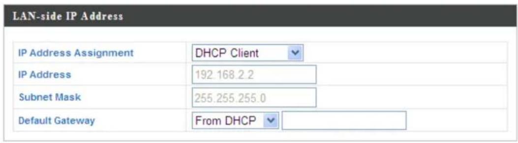

| IP Address Assignment | Select “DHCP Client” for your access point to be assigned a dynamic IP address from your router’s DHCP server, or select “Stac IP” to manually specify a stac/xed IP address for your access point (below). |
| IP Address | Specify the IP address here. This IP address will be assigned to your access point and will replace the default IP address. |
| Subnet Mask | Specify a subnet mask. The default value is 255.255.255.0 |
| Default Gateway | For DHCP users, select “From DHCP” to get default gateway from your DHCP server or “User-Dened” to enter a gateway manually. For stac IP users, the default value is blank. |
DHCP users can select to get DNS servers' IP address from DHCP or manually enter a value. For stac IP users, the default value is blank.
| Primary Address | DHCP users can select “From DHCP” to get primary DNS server’s IP address from DHCP or “User-Dened” to manually enter a value. For stac IP users, the default value is blank. |
| Secondary Address | DHCP users can select “From DHCP” to get secondary DNS server’s IP address from DHCP or “User-Dened” to manually enter a value. For stac IP users, the default value is blank. |
IV-2-2. LAN Port
LAN Port
The "LAN Port" page allows you to conjure the
sengs for your access point's two wired LAN (Ethernet) ports.
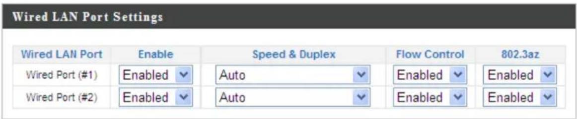
| Wired LAN Port | Idenes LAN port 1 or 2. |
| Enable | Enable/disable specied LAN port. |
| Speed & Duplex | Select a speed & duplex type for specied LAN port, or use the “Auto” value. LAN ports can operate up to 1000Mbps and full-duplex enables simultaneous data packet transfer/receive. |
| Flow Control | Enable/disable ow control. Flow control can pause new session request unl current data processing is complete, in order to avoid device overloads under heavy trac. |
| 802.3az | Enable/disable 802.3az. 802.3az is an Energy Ecient Ethernet feature which disables unused interfaces to reduce power usage. |
IV-2-3. V L A N

The "VLAN" (Virtual Local Area Network) enables you to congure VLAN sengs. A VLAN is a local area network which maps workstaons virtually instead of physically and allows you to group together or isolate users from each other. VLAN IDs 0 – 4094 are supported.

VLAN IDs in the range 0 - 4094 are supported.
| Wired LAN Port | VLAN Mode | VLAN ID |
| Wired Port (#1) | Untagged Port | 1 |
| Wired Port (#2) | Untagged Port | 1 |
| Wireless 2.4GHz | VLAN Mode | VLAN ID |
| SSID [WAP-5872u-FFC8E9_G] | Untagged Port | 1 |
| Wireless 5GHz | VLAN Mode | VLAN ID |
| SSID [WAP-5872u-FFC8E9_A] | Untagged Port | 1 |

| Wired LAN Port/Wireless | Idenes LAN port 1 or 2, or wireless SSIDs (2.4GHz or 5GHz). |
| VLAN Mode | Select “Tagged Port” or “Untagged Port” for specied LAN/wireless interface. |
| VLAN ID | Set a VLAN ID for specied interface, if “Untagged Port” is selected. |
| VLAN ID | Specify the VLAN ID of the subnet. Hosts belonging to the subnet can only communicate with other hosts on the same subnet. |
IV-3. Wireless Sengs


Screenshots displayed are examples. The informaon shown on your screen will vary depending on your conguraon.
IV-3-1. 2.4GHz 11bgn
2.4GHz 11bgn
The “2.4GHz 11bgn” menu allows you to view and congregate informaon for your access point’s 2.4GHz wireless network across four
categories: Basic, Advanced, Security and WDS.
IV-3-1-1. Basic

The "Basic" screen displays basic sengs for your access
point's 2.4GHz Wi-Fi network (s).
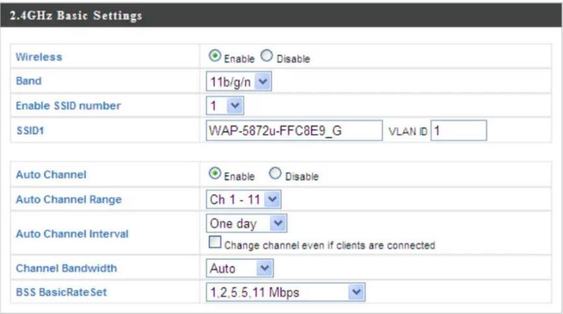


| Wireless | Enable or disable the access point's 2.4GHz wireless radio. When disabled, no 2.4GHz SSIDs will be acve. |
| Band | Select the wireless standard used for the access point. Combinaons of 802.11b, 802.11g & 802.11n can be selected. |
| Enable SSID Number | Select how many SSIDs to enable for the 2.4GHz frequency from the drop down menu. A maximum of 8 can be enabled. |
| SSID# | Enter the SSID name for the specied SSID (up to 8). The SSID can consist of any combinaon of up to 32 alphanumeric characters. |
| VLAN ID | Specify a VLAN ID for each SSID. |
| Auto Channel | Enable/disable auto channel selecon. Auto channel selecon will automacally set the wireless channel for the access point's 2.4GHz frequency based on availability and potenal interference. When disabled, select a channel manually as shown in the next table. |
| Auto Channel Range | Select a range from which the auto channel seng (above) will choose a channel. |
| Auto Channel Interval | Specify a frequency for how oen the auto channel seng will check/reassign the wireless channel. Check/uncheck the “Change channel even if clients are connected” box according to your preference. |
| Channel Bandwidth | Set the channel bandwidth: 20MHz (lower performance but less interference), 40MHz (higher performance but potentially higher interference) or Auto (automacally select based on interference level). |
| BSS BasicRate Set | Set a Basic Service Set (BSS) rate: this is the transmission rate for control communicaon frames for wireless clients. |
When auto channel is disabled, select a wireless channel manually:
| Channel Interval | Select a wireless channel from 1 – 13. |
| Channel Bandwidth | Set the channel bandwidth: 20MHz (lowerperformance but less interference), 40MHz (higher performance but potentially higher interference) or Auto (automacally select based on interference level). |
| BSS BasicRate Set | Set a Basic Service Set (BSS) rate: this is the transmission rate for control communicaon frames for wireless clients. |
IV-3-1-2. Advanced
Advanced
These sengs are for experienced users only. Please do not change any of the values on this page unless you are already familiar with these funcons.

Changing these sengs can adversely act the performance of your access point.
2.4GHz Advanced Settings
| Contention Slot | Short ▼ | |
| Preamble Type | Short ▼ | |
| Guard Interval | Short GI ▼ | |
| 802.11g Protection | ○ Enable ○ Disable | |
| 802.11n Protection | ○ Enable ○ Disable | |
| DTIM Period | 1 | (1-255) |
| RTS Threshold | 2347 | (1-2347) |
| Fragment Threshold | 2346 | (256-2346) |
| Multicast Rate | Auto ▼ | |
| Tx Power | 100% ▼ | |
| Beacon Interval | 100 | (40-1000 ms) |
| Station idle timeout | 60 | (30-65535 seconds) |
| Contenon Slot | Select “Short” or “Long” – this value is used for contenon windows in WMM (see IV-3-6. WMM). |
| Preamble Type | Set the wireless radio preamble type. The default value is “Short Preamble”. |
| Guard Interval | Set the guard interval. |
| 802.11g Protecon | Enable/disable 802.11g protecon, which increases reliability but reduces bandwidth (clients will send Request to Send (RTS) to access point, and access point will broadcast Clear to Send (CTS), before a packet is sent from client.) |
| 802.11n Protection | Enable/disable 802.11n protecon, which increases reliability but reduces bandwidth (clients will send Request to Send (RTS) to access point, and access point will broadcast Clear to Send (CTS), before a packet is sent from client.) |
| DTIM Period | Set the DTIM (delivery trac indicaon message) period value of the wireless radio. The default value is 1. |
| RTS Threshold | Set the RTS threshold of the wireless radio. The default value is 2347. |
| Fragment Threshold | Set the fragment threshold of the wireless radio. The default value is 2346. |
| Mulcast Rate | Set the transfer rate for mulcast packets or use the “Auto” seng. |
| Tx Power | Set the power output of the wireless radio. You may not require 100% output power. Seng a lower power output can enhance security since potenally malicious/unknown users in distant areas will not be able to access your signal. |
| Beacon Interval | Set the beacon interval of the wireless radio. The default value is 100. |
| Staon idle meout | Species the interval of the AP to probe for WLAN staons to verify if the staon is sll alive. The value ranges from 60 to 3600, in seconds. The default value is 60s. |
IV-3-1-3. Security
Security
The access point provides various security opons (wireless data encrypon). When data is encrypted, informaon transmied wirelessly cannot be read by anyone who does not know the correct encrypon key.

It is essenal to congregate wireless security in order to prevent unauthorised access to your network.

For opmal security, select a hard-to-guess password which include a combinaon of numbers, leers and symbols.
2.4GHz Wireless Security Settings
SSID
WAP-5872u-FFC8E9_G
Broadcast SSID
Enable
Wireless Client Isolation
Disable

Load Balancing
50 /50
Authentication Method
No Authentication
Additional Authentication
No additional authentication

| SSID Selection | Select which SSID to congregate security sengs for. |
| Broadcast ESSID | Enable or disable ESSID broadcast. When enabled, the ESSID will be visible to clients as an available Wi-Fi network. When disabled, the ESSID will not be visible as an available Wi-Fi network to clients – clients must manually enter the ESSID in order to connect. A hidden (disabled) ESSID is typically more secure than a visible (enabled) SSID. |
| Wireless Client Isolaon | Enable or disable wireless client isolaon.Wireless client isolaon prevents clients connected to the access point from communicang with each other and improves security. Typically, this funcon is useful for corporate environments or public hot spots and can prevent brute force aacks on clients' usernames and passwords. |
| Load Balancing | Load balancing limits the number of wireless clients connected to an SSID. Set a load balancing value (maximum 50). |
| Authencaon Method | Select an authencaon method from the drop down menu and refer to the informaon below appropriate for your method. |
| Addional Authencaon | Select an additional authencaon method from the drop down menu and refer to the informaon below (IV-3-1-3-6.) appropriate for your method. |
IV-3-1-3-1. No Authencaon
Authencaon is disabled and no password/key is required to connect to the access point.

Disabling wireless authencaon is not recommended. When disabled, anybody within range can connect to your network.
IV-3-1-3-2. WEP
WEP (Wired Equivalent Privacy) is a basic encrypon type. For a higher level of security consider using WPA encrypon.
| Key Length | Select 64-bit or 128-bit. 128-bit is more secure than 64-bit and is recommended. |
| Key Type | Choose from “ASCII” (any alphanumeric character 0-9, a-z and A-Z) or “Hex” (any characters from 0-9, a-f and A-F). |
| Default Key | Select which encrypon key (1 – 4 below) is the default key. For security purposes, you can set up to four keys (below) and change which is the default key. |
| Encrypon Key 1 – 4 | Enter your encrypon key/password according to the format you selected above. |
IV-3-1-3-3. IEEE802.1x/EAP
| Key Length | Select 64-bit or 128-bit. 128-bit is more secure than 64-bit and is recommended. |
IV-3-1-3-4. WPA-PSK
WPA-PSK is a secure wireless encrypon type with strong data protecon and user authencaon, utilizing 128-bit encrypon keys.
| WPA Type | Select from WPA/WPA2 Mixed Mode-PSK, WPA2 or WPA only. WPA2 is safer than WPA only, but not supported by all wireless clients. Please make sure your wireless client supports your selecon. |
| Encrypon | Select “TKIP/AES Mixed Mode” or “AES” encrypon type. |
| Key Renewal Interval | Specify a frequency for key renewal in minutes. |
| Pre-Shared Key Type | Choose from “Passphrase” (8 – 63 alphanumeric characters) or “Hex” (up to 64 characters from 0-9, a-f and A-F). |
| Pre-Shared Key | Please enter a security key/password according to the format you selected above. |
IV-3-1-3-5. WPA-EAP
| WPA Type | Select from WPA/WPA2 Mixed Mode-EAP, WPA2-EAP or WPA-EAP. |
| Encrypon | Select “TKIP/AES Mixed Mode” or “AES” encrypon type. |
| Key Renewal Interval | Specify a frequency for key renewal in minutes. |
IV-3-1-3-6. Additional Authencaon
Additional wireless authencaon methods can also be used:
MAC Address Filter
Restrict wireless clients access based on MAC address specied in the MAC Iter table.

See IV-3-5.MAC Filter to congregate MAC Itering.
MAC-RADIUS Authencaon
Restrict wireless clients access based on MAC address via a RADIUS server, or password authencaon via a RADIUS server.

See IV-3-4.RADIUS to congure RADIUS servers.

WPS must be disabled to use MAC-RADIUS authencaon. See IV-3-3. for WPS sengs.
| MAC RADIUS Password | Use MAC addressUse the following password |
| MAC RADIUSPassword | Select whether to use MAC address or password authencaon via RADIUS server. If you select “Use the following password”, enter the password in the eld below. The password should match the “Shared Secret” used in IV-3-4. RADIUS. |
MAC Filter & MAC-RADIUS Authencaon
Restrict wireless clients access using both of the above MAC Itering & RADIUS authencaon methods.
IV-3-1-4. WDS
WDS
Wireless Distribuon System (WDS) can bridge/repeat access points together in an extended network. WDS sengs can be congured as shown below.

When using WDS, congregate the IP address of each access point to be in the same subnet and ensure there is only one acve DHCP server among connected access points, preferably on the WAN side.
WDS must be congured on each access point, using correct MAC addresses. All access points should use the same wireless channel and WEP key.
2.4GHz
WDS Functionality
Local MAC Address
Disabled
00:1D:20:FF:C8:E9

WDS Peer Settings
WDS #1
WDS #2
WDS #3
WDS #4
MAC Address
MAC Address
MAC Address
MAC Address
WDS VLAN
VLAN Mode
VLAN ID
Untagged Port
-
WDS Encryption method
Encryption
None

| WDS Funconality | Select “WDS with AP” to use WDS or “WDS Dedicated Mode” to use WDS and also block communicaon with regular wireless clients. When WDS is used, each access point should be congured with corresponding MAC addresses, wireless channel and WEP key. |
| Local MAC Address | Displays the MAC address of your access point. |
| WDS # | Enter the MAC address for up to four other WDA devices you wish to connect. |
| VLAN Mode | Specify the WDS VLAN mode. |
| VLAN ID | Specify the WDS VLAN ID. |
| Encrypon | Select whether to use “None” or “AES” encrypon and enter a pre-shared key for AES. |
IV-3-2. 5GHz 11ac 11an

The "5GHz 11ac 11an" menu allows you to view and congregate informaon for your access point's
2.4GHz wireless network across four categories: Basic, Advanced, Security and WDS.
IV-3-2-1. Basic

The “Basic” screen displays basic sengs for your access etwork (s).
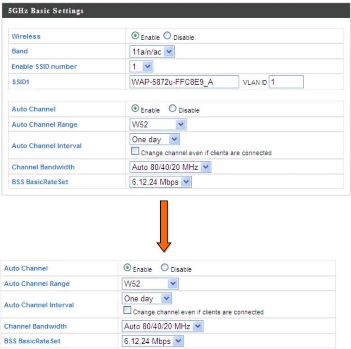
| Wireless | Enable or disable the access point's 5GHz wireless radio. When disabled, no 5GHz SSIDs will be acve. |
| Band | Select the wireless standard used for the access point. Combinaons of 802.11a, 802.11n & 802.11ac can be selected. |
| Enable SSID Number | Select how many SSIDs to enable for the 5GHz frequency from the drop down menu. A maximum of 8 can be enabled. |
| SSID# | Enter the SSID name for the specied SSID (up to 8). The SSID can consist of any combinaon of up to 32 alphanumeric characters. |
| VLAN ID | Specify a VLAN ID for each SSID. |
| Auto Channel | Enable/disable auto channel selecon. Auto channel selecon will automacally set the wireless channel for the access point's 5GHz frequency based on availability and potenal interference. When disabled, select a channel manually as shown in the next table. |
| Auto Channel Range | Select a range from which the auto channel seng (above) will choose a channel. |
| Auto Channel Interval | Specify a frequency for how oen the auto channel seng will check/reassign the wireless channel. Check/uncheck the “Change channel even if clients are connected” box according to your preference. |
| Channel Bandwidth | Set the channel bandwidth: 20MHz (lower performance but less interference), Auto 40/20MHz or Auto 80/40/20MHz (automacally select based on interference level). |
| BSS BasicRate Set | Set a Basic Service Set (BSS) rate: this is the transmission rate for control communicaon frames for wireless clients. |
When auto channel is disabled, select a wireless channel manually:
| Channel Interval | Select a wireless channel. |
| Channel Bandwidth | Set the channel bandwidth: 20MHz (lowerperformance but less interference), Auto 40/20MHz or Auto 80/40/20MHz (automacally select based on interference level). |
| BSS BasicRate Set | Set a Basic Service Set (BSS) rate: this is the transmission rate for control communicaon frames for wireless clients. |
IV-3-2-2. Advanced

These sengs are for experienced users only. Please do the values on this page unless you are already familiar with

Changing these sengs can adversely act the performance of your access point.
| Guard Interval | Short GI | |
| 802.11n Protection | Enable | Disable |
| DTIM Period | 1 | (1-255) |
| RTS Threshold | 2347 | (1-2347) |
| Fragment Threshold | 2346 | (256-2346) |
| Multicast Rate | Auto | |
| Tx Power | 100% | |
| Beacon Interval | 100 | (40-1000 ms) |
| Station idle timeout | 60 | (30-65535 seconds) |
| Guard Interval | Set the guard interval. |
| 802.11n Protection | Enable/disable 802.11n protecon, which increases reliability but reduces bandwidth (clients will send Request to Send (RTS) to access point, and access point will broadcast Clear to Send (CTS), before a packet is sent from client.) |
| DTIM Period | Set the DTIM (delivery trac indicaon message) period value of the wireless radio. The default value is 1. |
| RTS Threshold | Set the RTS threshold of the wireless radio. The default value is 2347. |
| Fragment Threshold | Set the fragment threshold of the wireless radio. The default value is 2346. |
| Mulcast Rate | Set the transfer rate for mulcast packets or use the “Auto” seng. |
| Tx Power | Set the power output of the wireless radio. You may not require 100% output power. Seng a lower power output can enhance security since potenally malicious/unknown users in distant areas will not be able to access your signal. |
| Beacon Interval | Set the beacon interval of the wireless radio. The default value is 100. |
| Staon idle meout | Species the interval of the AP to probe for WLAN staons to verify if the staon is sll alive. The value ranges from 60 to 3600, in seconds. The default value is 60s. |
IV-3-2-3. Security
Security
The access point provides various security opons (wireless data encrypon). When data is encrypted, informaon transmied wirelessly cannot be read by anyone who does not know the correct encrypon key.

It is essenal to congregate wireless security in order to prevent unauthorised access to your network.

For opmal security, select a hard-to-guess password which include a combinaon of numbers, leers and symbols.
5GHz Wireless Security Settings
| SSID | WAP-5872u-FFC8E9_A |
| Broadcast SSID | Enable |
| Wireless Client Isolation | Disable |
| Load Balancing | 50 /50 |
| Authentication Method | No Authentication |
| Additional Authentication | No additional authentication |
| SSID Selection | Select which SSID to congregate security sengs for. |
| Broadcast ESSID | Enable or disable ESSID broadcast. When enabled, the ESSID will be visible to clients as an available Wi-Fi network. When disabled, the ESSID will not be visible as an available Wi-Fi network to clients – clients must manually enter the ESSID in order to connect. A hidden (disabled) ESSID is typically more secure than a visible (enabled) SSID. |
| Wireless Client Isolaon | Enable or disable wireless client isolaon.Wireless client isolaon prevents clients connected to the access point from communicang with each other and improves security. Typically, this funcon is useful for corporate environments or public hot spots and can prevent brute force aacks on clients' usernames and passwords. |
| Load Balancing | Load balancing limits the number of wireless clients connected to an SSID. Set a load balancing value (maximum 50). |
| Authencaon Method | Select an authencaon method from the drop down menu and refer to the informaon below appropriate for your method. |
| Additional Authencaon | Select an additional authencaon method from the drop down menu and refer to the informaon below appropriate for your method. |
Please refer back to secon IV-3-1-3. Security for more informaon on authencaon and additional authencaon types.
IV-3-2-4. WDS
WDS
Wireless Distribuon System (WDS) can bridge/repeat access points together in an extended network. WDS sengs can be congured as shown below.

When using WDS, congregate the IP address of each access point to be in the same subnet and ensure there is only one acve DHCP server among connected access points, preferably on the WAN side.
WDS must be congured on each access point, using correct MAC addresses. All access points should use the same wireless channel and WEP key.
5GHz WDS Mode
WDS Functionality
Local MAC Address
Disabled
00:1D:20:FF:C8:EA

WDS Peer Settings
WDS #1
MAC Address
WDS #2
MAC Address
WDS #3
MAC Address
WDS #4
MAC Address
WDS VLAN
VLAN Mode
Untagged Port
VLAN ID
1
Encryption method
Encryption
None

| WDS Funconality | Select “WDS with AP” to use WDS or “WDS Dedicated Mode” to use WDS and also block communicaon with regular wireless clients. When WDS is used, each access point should be congured with corresponding MAC addresses, wireless channel and WEP key. |
| Local MAC Address | Displays the MAC address of your access point. |
| WDS # | Enter the MAC address for up to four other WDA devices you wish to connect. |
| VLAN Mode | Specify the WDS VLAN mode. |
| VLAN ID | Specify the WDS VLAN ID. |
| Encrypon | Select whether to use “None” or “AES” encrypon and enter a pre-shared key for AES. |
IV-3-3. WPS
WPS
Wi-Fi Protected Setup is a simple way to establish connecons between WPS compatible devices. WPS can be acvated on compatible devices by pushing a WPS buon on the device or from within the device's rmware/conguraon interface (known as PBC or "Push Buon Conguraon"). When WPS is acvated in the correct manner and at the correct me for two compatible devices, they will automacally connect. "PIN code WPS" is a variaon of PBC which includes the additional use of a PIN code between the two devices for vericaon.

Please refer to manufacturer's instrucons for your other WPS device.
WPS

Enable
Apply
WPS
Product PIN
58327524
Generate PIN
Push-button WPS
Start
WPS by PIN
Start
WPS Security
WPS Status
Not Configured
Release
| WPS | Check/uncheck this box to enable/disable WPS funconality. WPS must be disabled when using MAC-RADIUS authencaon (see IV-3-1-3-6 & IV-3-4). |
| Product PIN | Displays the WPS PIN code of the device, used for PIN code WPS. You will be required to enter this PIN code into another WPS device for PIN code WPS. Click “Generate PIN” to generate a new WPS PIN code. |
| Push-Buon WPS | Click “Start” to acvate WPS on the access point for approximately 2 minutes. This has the same eect as physically pushing the access point’s WPS buon. |
| WPS by PIN | Enter the PIN code of another WPS device and click “Start” to aempt to establish a WPS conncon for approximately 2 minutes. |
| WPS Status | WPS security status is displayed here. Click “Release” to clear the exisng status. |
IV-3-4. RADIUS
> RADIUS
The RADIUS sub menu allows you to congregate the access point's RADIUS server sengs, categorized into three submenus: RADIUS sengs, Internal Server and RADIUS accounts.
A RADIUS server provides user-based authencaon to improve security and oer wireless client control – users can be authenticated before gaining access to a network.
The access point can ulize both a primary and secondary (backup) RADIUS server for each of its wireless frequencies (2.4GHz & 5GHz). External RADIUS servers can be used or the access point's internal RADIUS server can be used.

To use RADIUS servers, go to “Wireless Sengs” → “Security” and select “MAC RADIUS Authencaon” → “Additional
Authencaon" and select "MAC RADIUS Authencaon" (see IV-3-1-3. & IV-3-2-3).
IV-3-4-1. RADIUS Sengs
RADIUS Settings
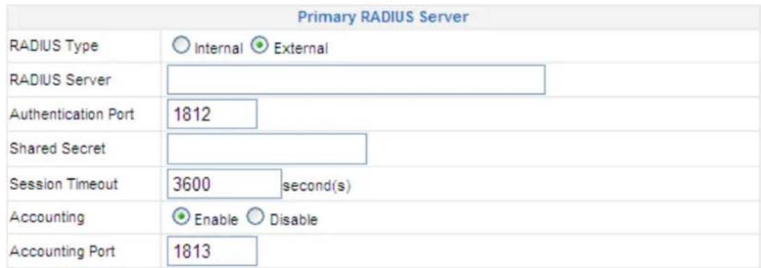
Congure the RADIUS server sengs for 2.4GHz & 5GHz.
Each frequency can use a primary and secondary (backup) RADIUS server.
RADIUS Server (2.4GHz)
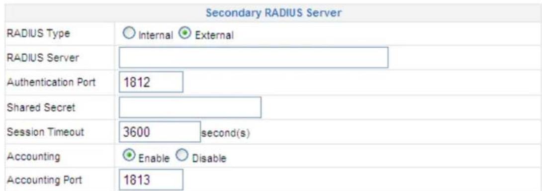
RADIUS Server (5GHz)
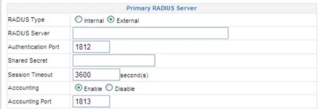
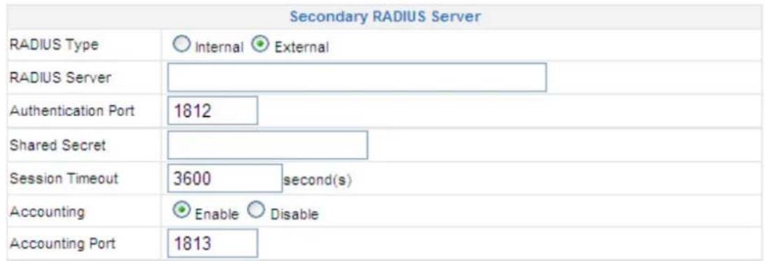
| RADIUS Type | Select “Internal” to use the access point's built-in RADIUS server or “external” to use an external RADIUS server. |
| RADIUS Server | Enter the RADIUS server host IP address. |
| Authencaon Port | Set the UDP port used in the authencaon protocol of the RADIUS server. Value must be between 1 – 65535. |
| Shared Secret | Enter a shared secret/password between 1 – 99 characters in length. This should match the “MAC-RADIUS” password used in IV-3-1-3-6 or IV-3-2-3. |
| Session Timeout | Set a duraon of session meout in seconds between 0 – 86400. |
| Accounting | Enable or disable RADIUS accoung. |
| Accounting Port | When accoung is enabled (above), set the UDP port used in the accoung protocol of the RADIUS server. Value must be between 1 – 65535. |
IV-3-4-2. Internal Server

The access point features a built-in RADIUS server which can be congured as shown below. When “Internal” is selected for “RADIUS Type” in the “Wireless Sengs” → “RADIUS” → “RADIUS Sengs” menu.

To use RADIUS servers, go to "Wireless Sengs" → "Security" and select "MAC RADIUS Authencaon" → "Additional
Authencaon" and select "MAC RADIUS Authencaon" (see IV-3-1-3. & IV-3-2-3).
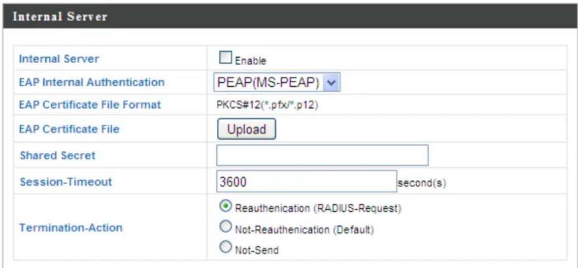
| Internal Server | Check/uncheck to enable/disable the access point's internal RADIUS server. |
| EAP Internal Authencaon | Select EAP internal authencaon type from the drop down menu. |
| EAP Cercate File Format | Displays the EAP cercate le format: PCK#12(*.pfx/*.p12) |
| EAP Cercate File | Click “Upload” to open a new window and select the locaon of an EAP cercate le to use. If no cercate le is uploaded, the internal RADIUS server will use a self-made cercate. |
| Shared Secret | Enter a shared secret/password for use between the internal RADIUS server and RADIUS client.The shared secret should be 1 – 99 characters in length. This should match the “MAC-RADIUS” password used in IV-3-1-3-6 or IV-3-2-3. |
| Session Timeout | Set a duraon of session meout in seconds between 0 – 86400. |
| Terminaon Acon | Select a terminaon-acon aribute: “Reauthencaon” sends a RADIUS request to the access point, “Not-Reathencaon” sends a default terminaon-acon aribute to the access point, “Not-Send” no terminaon-acon aribute is sent to the access point. |
IV-3-4-3. RADIUS Accounts
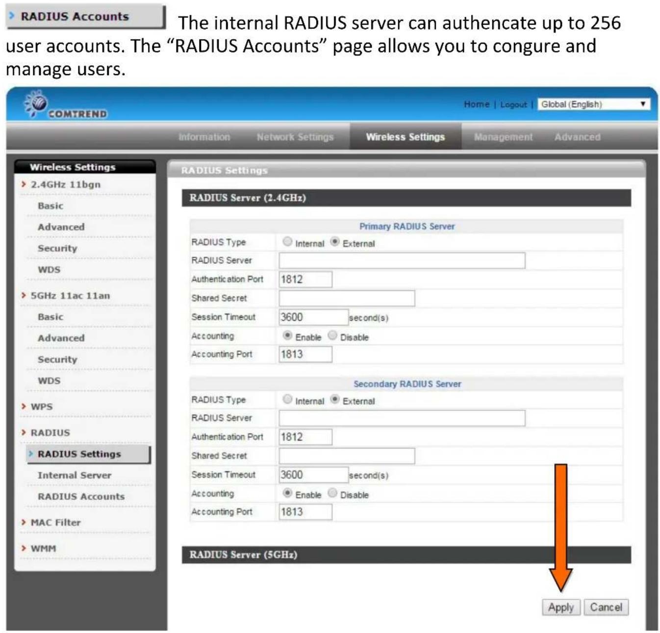

| User Name | Enter a user name here. |
| Add | Click “Add” to add the user to the user registraon list. |
| Reset | Clear text from the user name box. |
| Select | Check the box to select a user. |
| User Name | Displays the user name. |
| Password | Displays if specied user name has a password (congured) or not (not congured). |
| Customize | Click “Edit” to open a new eld to set/edit a password for the specied user name (below). |
| Delete Selected | Delete selected user from the user registraon list. |
| Delete All | Delete all users from the user registraon list. |
Edit User Registraon List
| User Name | Exisng user name is displayed here and can be edited according to your preference. |
| Password | Enter or edit a password for the specied user. |
IV-3-5. MAC Filter

Mac Itering is a security feature that can help to
prevent unauthorized users from connecng to your access point.
This funcon allows you to denote a list of network devices permitted to connect to the access point. Devices are each idened by their unique MAC address. If a device which is not on the list of permied MAC addresses aempts to connect to the access point, it will be denied.

To enable MAC Itering, go to "Wireless Sengs" → "2.4GHz
11bgn/5GHz 11ac 11an" → "Security" → "Additional
Authencaon" and select "MAC Filter" (see IV-3-1-3. & IV-3-2-3).
The MAC address Itering table is displayed below:
| MAC Address Filtering Table | |
| Select | MAC Address |
| □ | 00:1C:BF:10:CB:68 |

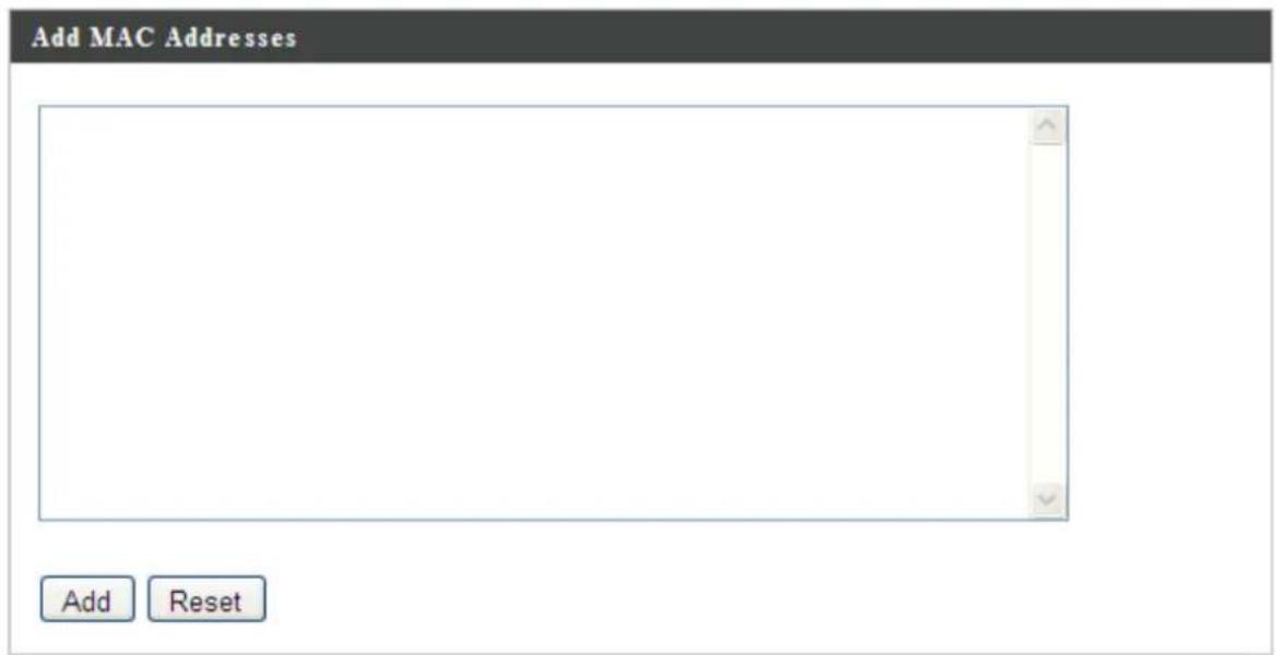
| Add MAC Address | Enter a MAC address of computer or network device manually without dashes or colons e.g. for MAC address ‘aa-bb-cc-dd-ee-’ enter ‘aabbccddee’. |
| Add | Click “Add” to add the MAC address to the MAC address Itering table. |
| Reset | Clear all elds. |
MAC address entries will be listed in the “MAC Address Filtering Table”. Select an entry using the “Select” checkbox.
| Select | Delete selected or all entries from the table. |
| MAC Address | The MAC address is listed here. |
| Delete Selected | Delete the selected MAC address from the list. |
| Delete All | Delete all entries from the MAC addressItering table. |
| Export | Click “Export” to save MAC address Itering as a le to your local computer. |
IV-3-6. WMM
WMM
Wi-Fi Mulmedia (WMM) is a Wi-Fi Alliance
interoperability cercaon based on the IEEE 802.11e standard, which provides Quality of Service (QoS) features to IEE 802.11 networks. WMM prioritizes trac according to four categories: background, best eort, video and voice.
WMM-EDCA Settings
| WMM Parameters of Access Point | ||||
| CWMin | CWMax | AIFSN | TxOP | |
| Back Ground | 4 | 10 | 7 | 0 |
| Best Effort | 4 | 6 | 3 | 0 |
| Video | 3 | 4 | 1 | 94 |
| Voice | 2 | 3 | 1 | 47 |
WMM Parameters of Station
| CWMin | CWMax | AIFSN | TxOP | |
| Back Ground | 4 | 10 | 7 | 0 |
| Best Effort | 4 | 10 | 3 | 0 |
| Video | 3 | 4 | 2 | 94 |
| Voice | 2 | 3 | 2 | 47 |
Conguring WMM consists of adjusng parameters on queues for dierent categories of wireless trac. Trac is sent to the following queues:
| Background | Low Priority | High throughput, non me sensitive bulk data e.g. FTP |
| Best Eort | Medium Priority | Tradional IP data, medium throughput and delay. |
| Video | High Priority | Time sensitive video data with minimum me delay. |
| Voice | High Priority | Time sensitive data such as VoIP and streaming media with minimum me delay. |
Queues automacally provide minimum transmission delays for video, voice, mulmedia and crical applicaons. The values can further be adjusted manually:
| CWMin | Minimum Contenon Window (milliseconds): This value is input to the initial random backo wait me algorithm for retry of a data frame transmission. The backo wait me will be generated between 0 and this value. If the frame is not sent, the random backo value is doubled until the value reaches the number dened by CWMax (below). Valid values are 1, 3, 7, 15, 31, 63, 127, 255, 511 or 1024. The CWMin value must be lower than the CWMax value. The contenon window scheme helps to avoid frame collisions and determine priority of frame transmission. A shorter window has a higher probability (priority) of transmission. |
| CWMax | Maximum Contenon Window (milliseconds): This value is the upper limit to random backo value doubling (see above). Valid values are 1, 3, 7, 15, 31, 63, 127, 255, 511 or 1024. |
| AIFSN | Arbitraon Inter-Frame Space (milliseconds): Species additional me between when a channel goes idle and the AP/client sends data frames. Trac with a lower AIFSN value has a higher priority. |
| TxOP | Transmission Opportunity (milliseconds): The maximum interval of me an AP/client can transmit. This makes channel access more eciently prioritized. A value of 0 means only one frame per transmission. A greater value eects higher priority. |
IV-4. Management


Screenshots displayed are examples. The informaon shown on your screen will vary depending on your conguraon.
IV-4-1. Admin

You can change the password used to login to the browser-based conguraon interface here. It is advised to do so for security purposes.

If you change the administrator password, please make a note of the new password. In the event that you forget this password and are unable to login to the browser based conguraon interface, see secon 1-5. Reset for how to reset the access point.
Account to Manage This Device
| Administrator Name | admin | |
| Administrator Password | ●●●●● | (4-32 Characters) |
| ●●●●● | (Confirm) |
Apply
Advanced Settings
| Product Name | AP001D20FFC8E9 |
| Management Protocol | HTTP HTTPS TELNET SSH SNMP |
| SNMP Version | v1/v2c |
| SNMP Get Community | public |
| SNMP Set Community | private |
| SNMP Trap | Disabled |
| SNMP Trap Community | public |
| SNMP Trap Manager |
| Administrator Name | Set the access point’s administrator name.This is used to log in to the browser based conguraon interface. |
| Administrator Password | Set the access point’s administrator password.This is used to log in to the browser based conguraon interface. |
| Product Name | Edit the product name according to your preference. This name is used for reference purposes. |
| Management Protocol | Check/unchecked the boxes to enable/disable specied management interfaces (see below). When SNMP is enabled, complete the SNMP elds below. |
| SNMP Version | Select SNMP version appropriate for your SNMP manager. |
| SNMP Get Community | Enter an SNMP Get Community name for vericaon with the SNMP manager for SNMP-GET requests. |
| SNMP Set Community | Enter an SNMP Set Community name for vericaon with the SNMP manager for SNMP-SET requests. |
| SNMP Trap | Enable or disable SNMP Trap to nofy SNMP manager of network errors. |
| SNMP Trap Community | Enter an SNMP Trap Community name for vericaon with the SNMP manager for SNMP-TRAP requests. |
| SNMP Trap Manager | Specify the IP address or sever name (maximum 128 characters) of the SNMP manager. |
HTTP
Internet browser HTTP protocol management interface
HTTPS
Internet browser HTTPS protocol management interface
TELNET
Client terminal with telnet protocol management interface
SSH
Client terminal with SSH protocol version 1 or 2 management interface
SNMP
Network management protocol. SNMPv1, v2 & v3 protocol supported.
SNMPv2 can be used with community based authencaon. SNMPv3 uses user-based security model (UM) architecture.
IV-4-2. Date and Time
Date and Time
You can congregate the me zone sengs of your access
point here. The date and me of the device can be congured manually or can be synchronized with a me server.
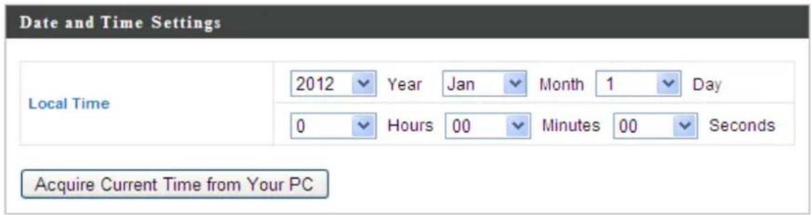

| Local Time | Set the access point’s date and me manually using the drop down menus. |
| Acquire Current Time from your PC | Click “Acquire Current Time from Your PC” to enter the required values automacally according to your computer’s current me and date. |
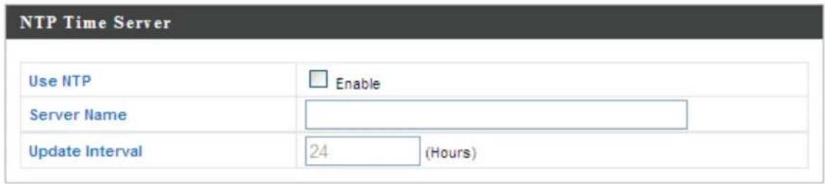
| Use NTP | The access point also supports NTP (Network Time Protocol) for automac me and date setup. |
| Server Name | Enter the host name or IP address of the me server if you wish. |
| Update Interval | Specify a frequency (in hours) for the access point to update/synchronize with the NTP server. |
| Time Zone | Select the me zone of your country/ region. If your country/region is not listed, please select another country/region whose me zone is the same as yours. |
IV-4-3. Syslog Server

The system log can be sent to a server or to aached
USB storage.
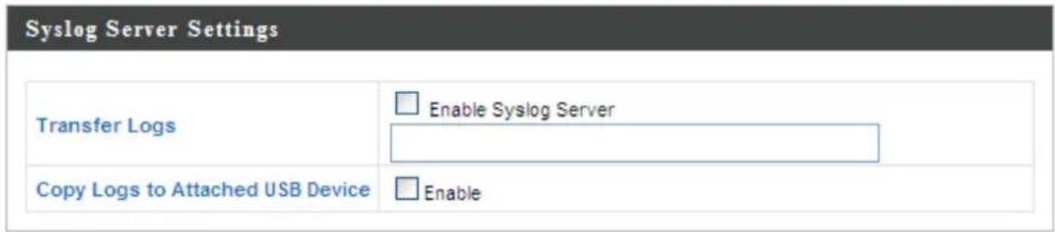
| Transfer Logs | Check/uncheck the box to enable/disable the use of a syslog server, and enter a host name, domain or IP address for the server, consisng of up to 128 alphanumeric characters. |
| Copy Logs to Aached USB Device | Check/uncheck the box to enable/disable copying logs to aached USB storage. |
IV-4-4. I'm Here
I'm Here
The access point features a built-in buzzer which can sound on command using the “I’m Here” page. This is useful for network administrators and engineers working in complex network environments to locate the access point.

Sound Buzzer

The buzzer is loud!
| Duraon of Sound | Set the duraon for which the buzzer will sound when the “Sound Buzzer” buon is clicked. |
| Sound Buzzer | Acvate the buzzer sound for the above specied duraon of me. |
IV-5. Advanced


Screenshots displayed are examples. The informaon shown on your screen will vary depending on your conguraon.
IV-5-1. LED Sengs

The access point's LEDs can be manually enabled or your preference.
| LED Settings | |
| Power LED | On Off |
| Diag LED | On Off |
| Power LED | Select on or o. |
| Diag LED | Select on or o. |
IV-5-2. Update Firmware
Update Firmware
The "Firmware" page allows you to update the system rmware to a more recent version. Updated rmware versions oen oer increased performance and security, as well as bug xes.
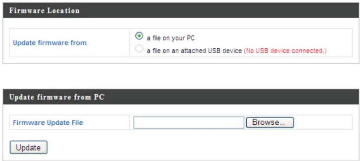

Do not switch o or disconnect the access point during a rmware upgrade, as this could damage the device.
| Update Firmware From | Select to upload rmware from your local computer or from an aached USB device. |
| Firmware Update File | Click “Browse” to open a new window to locate and select the rmware le in your computer. |
| Update | Click “Update” to upload the specied rmware le to your access point. |
IV-5-3. Save/Restore Sengs
The access point's "Save/Restore Setngs" page enables you to save/backup the access point's current sengs as a le to your local computer or a USB device aached to the access point, and restore the access point to previously saved sengs.
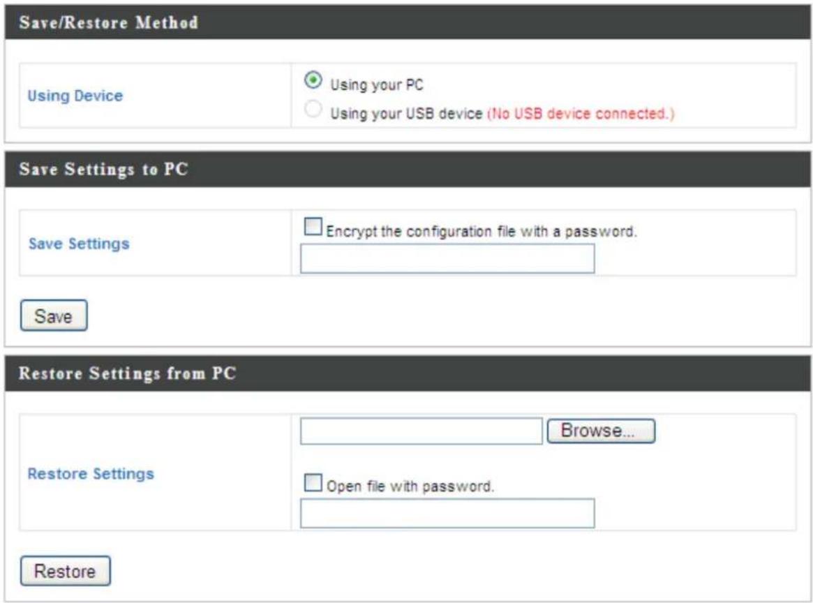
| Using Device | Select to save the access point’s sengs to your local computer or to an aached USB device. |
| Save Sengs | Click “Save” to save sengs and a new window will open to specify a locaon to save the sengs le. If saving sengs to your computer, you can also check the “Encrypt the conguraon le with a password” box and enter a password to protect the le in the eld underneath, if you wish. |
| Restore Sengs | Click the browse buon to nd a previously saved sengs le and then click “Restore” to replace your current sengs. If your sengs le is encrypted with a password, check the “Open le with password” box and enter the password in the eld underneath. |
IV-5-4. Factory Default
Factory Default
If the access point malfuncons or is not responding,
then it is recommended that you reboot the device (see IV-5.5) or reset the device back to its factory default sengs. You can reset the access point back to its default sengs using this feature if the locaon of the access point is not convenient to access the reset buon.
This will restore all settings to factory defaults.
Factory Default
Factory Default
Click "Factory Default" to restore sengs to the factory default. A pop-up window will appear and ask you to conrm.

Aer reseng to factory defaults, please wait for the access point to reset and restart.
IV-5-5. Reboot
Reboot
If the access point malfuncons or is not responding,
then it is recommended that you reboot the device or reset the access point back to its factory default sengs (see IV-5-4). You can reboot the access point remotely using this feature.
This will reboot the product. Your settings will not be changed. Click "Reboot" to reboot the product now.
Reboot
Reboot
Click "Reboot" to reboot the device. A countdown will indicate the progress of the reboot.
V-1. Conguring your IP address
The access point uses the default IP address 192.168.2.2. In order to access the browser based conguraon interface, you need to modify the IP address of your computer to be in the same IP address subnet e.g. 192.168.2.x (x = 3 - 254).
The procedure for modifying your IP address varies across dierent operang systems; please follow the guide appropriate for your operang system.
In the following examples we use the IP address 192.168.2.10 though you can use any IP address in the range 192.168.2.x (x = 3 - 254).
V-1-1. Windows XP
- Click the “Start” buon (it should be located in the lower-le corner of your computer), then click “Control Panel”. Double-click the “Network and Internet Connecons” icon, click “Network Connecons”, and then double-click “Local Area Connecon”. The “Local Area Connecon Status” window will then appear, click “Properes”.
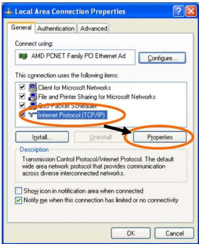
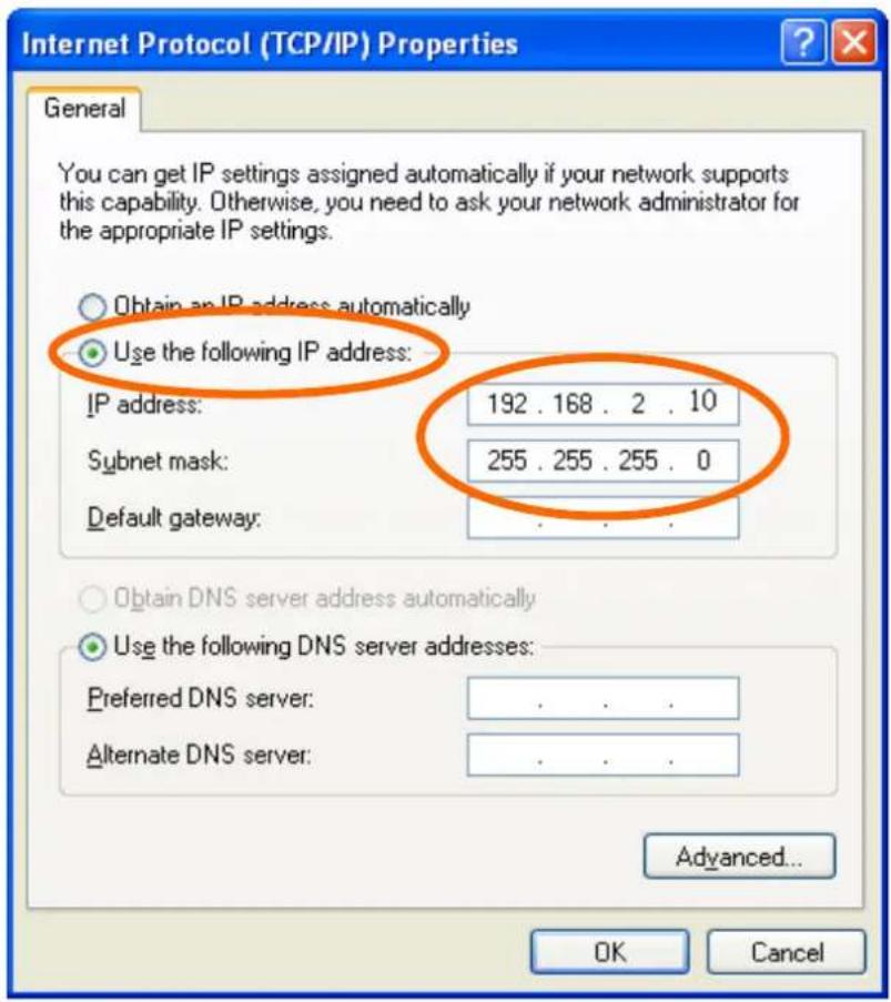
- Select "Use the following IP address", then input the following values:
IP address: 192.168.2.10
Subnet Mask: 255.255.255.0
Click 'OK' when nished.
V-1-2. Windows Vista
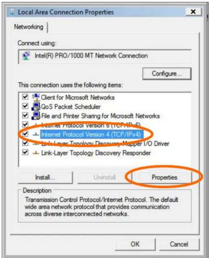
- Click the “Start” buon (it should be located in the lower-le corner of your computer), then click “Control Panel”. Click “View Network Status and Tasks”, then click “Manage Network Connecons”. Right-click “Local Area Network”, then select “Properes”. The “Local Area Connecon Properes” window will then appear, select “Internet Protocol Version 4 (TCP / IPv4)”, and then click “Properes”.
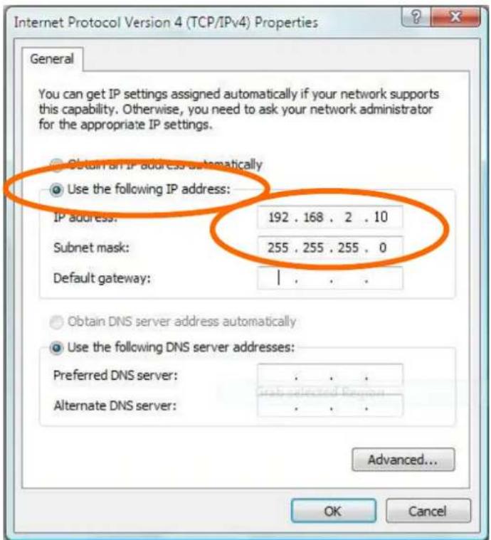
- Select "Use the following IP address", then input the following values:
IP address: 192.168.2.10
Subnet Mask: 255.255.255.0
Click 'OK' when nished.
V-1-3. Windows 7
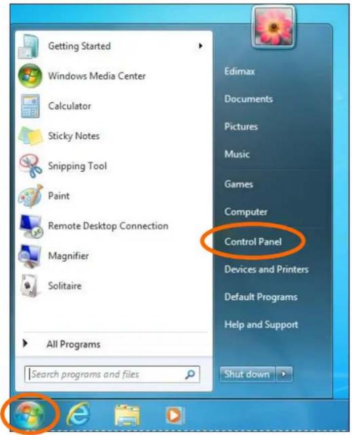
- Click the "Start" buon (it should be located in the lower-le corner of your computer), then click "Control Panel".
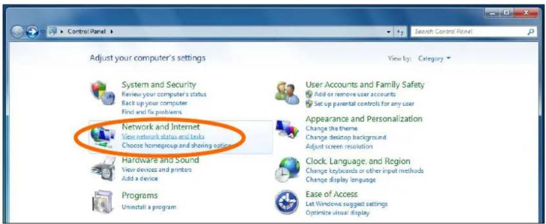
- Under "Network and Internet" click "View network status and tasks".
- Click "Local Area Connecon".
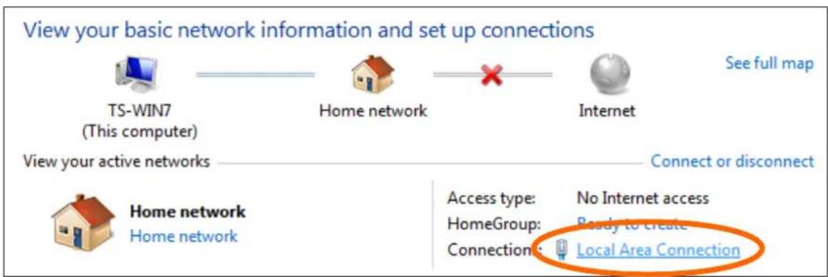
4. Click "Properes".
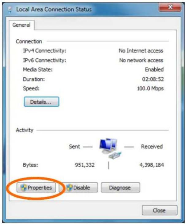
- Select "Internet Protocol Version 4 (TCP/IPv4) and then click "Properes".
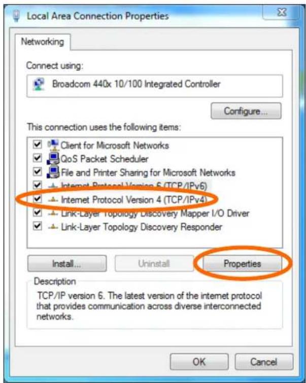
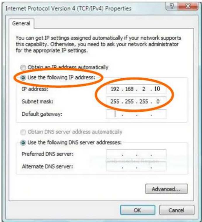
- Select "Use the following IP address", then input the following values:
IP address: 192.168.2.10
Subnet Mask: 255.255.255.0
Click 'OK' when nished.
V-1-4. Windows 8
- From the Windows 8 Start screen, you need to switch to desktop mode. Move your cursor to the boom le of the screen and click.
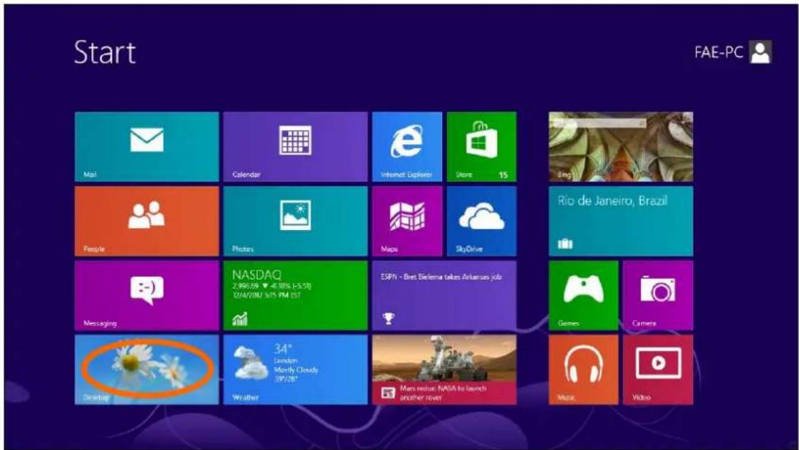
- In desktop mode, click the File Explorer icon in the boom le of the screen, as shown below.

natural_image
Close-up of white daisies against a blue sky, no text or symbols visible on the daisies or background.3. Right click "Network" and then select "Properes".
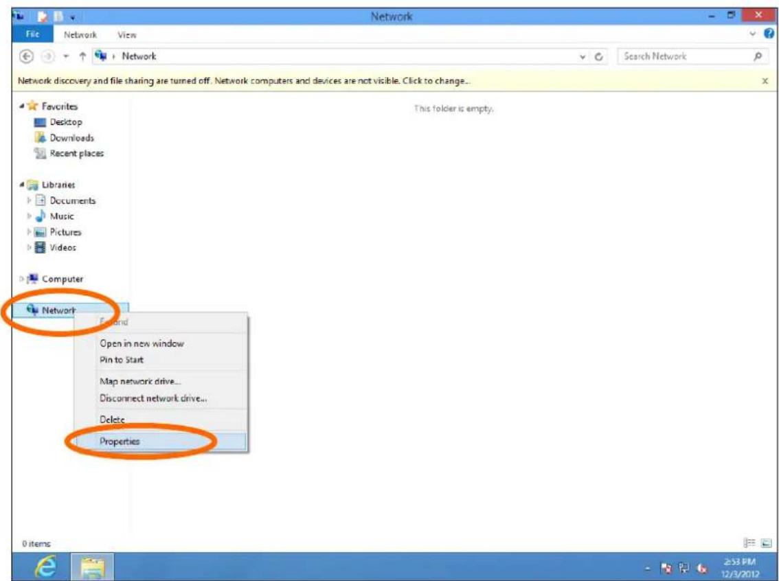
4. In the window that opens, select "Change adapter setngs" from the le side.
5.
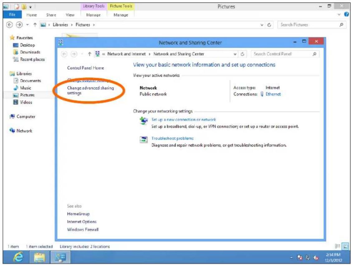
6. Choose your conncon and right click, then select "Properes".
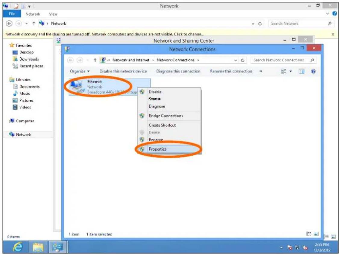
7. Select "Internet Protocol Version 4 (TCP/IPv4) and then click "Properes".
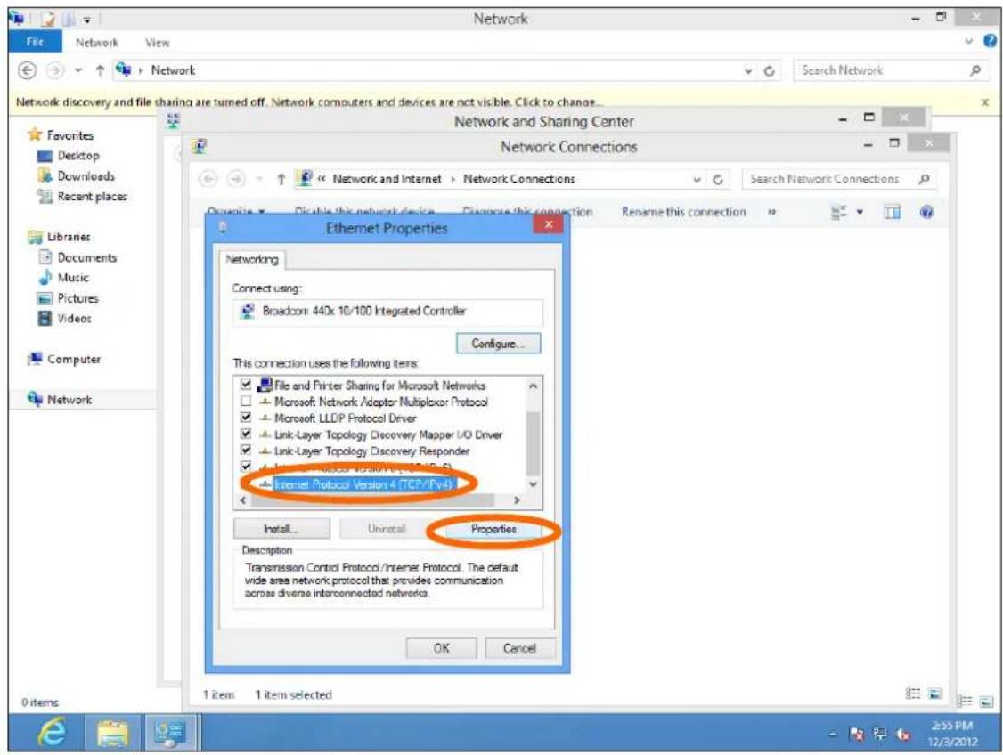
8. Select "Use the following IP address", then input the following values:
IP address: 192.168.2.10
Subnet Mask: 255.255.255.0
Click 'OK' when nished.
IV-1-5. Mac
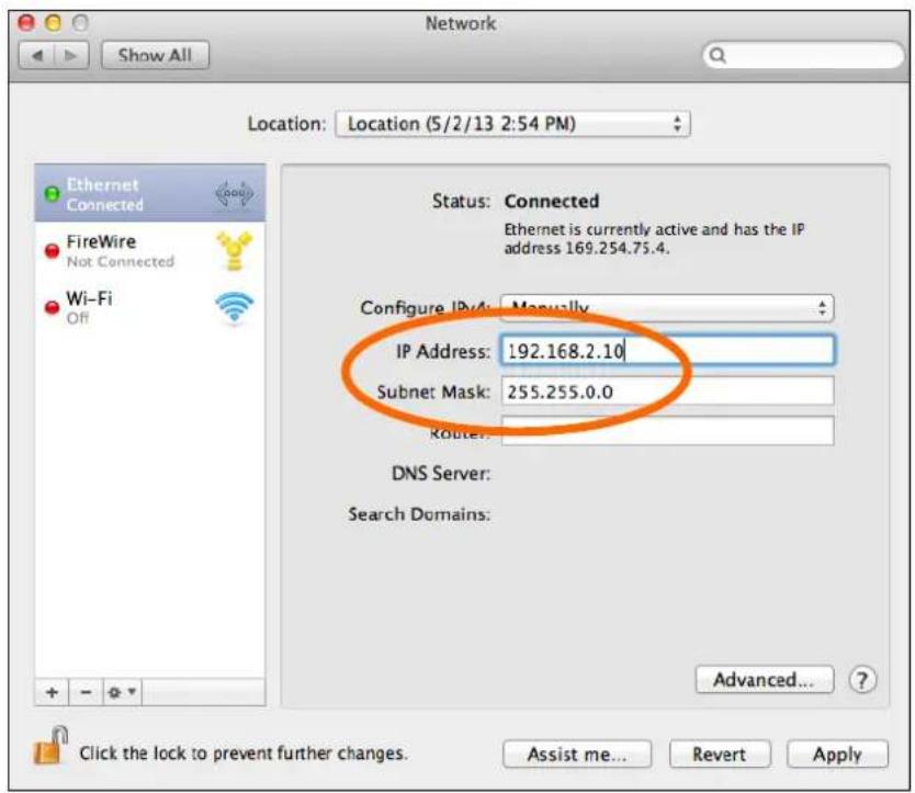
- Have your Macintosh computer operate as usual, and click on "System Preferences"

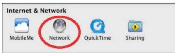
- In System Preferences, click on "Network".
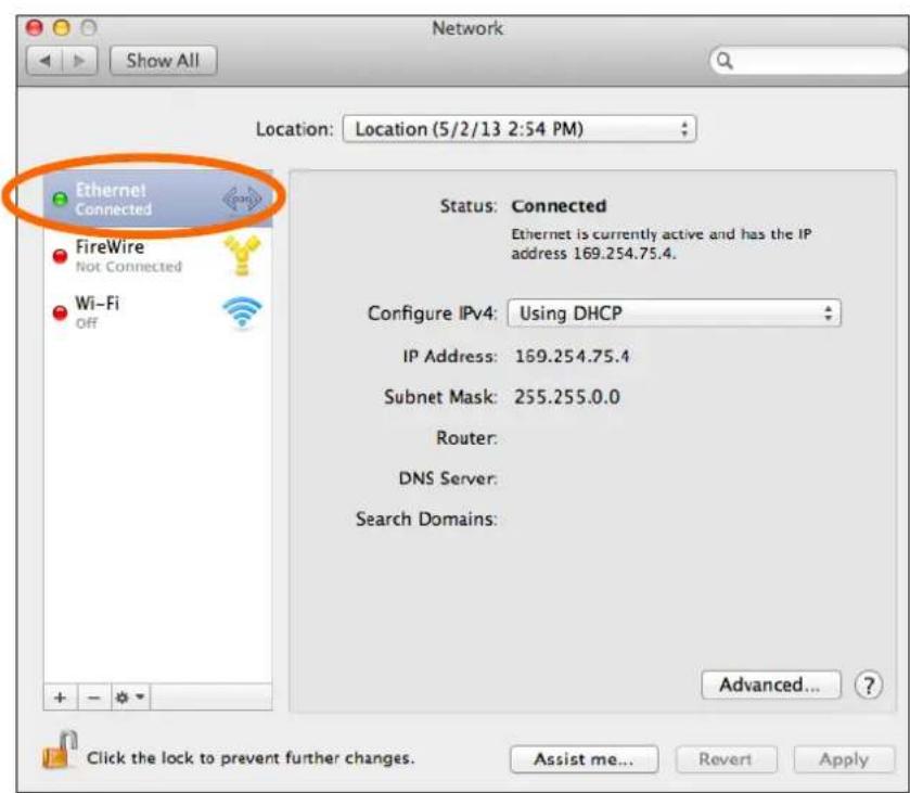
- Click on "Ethernet" in the le panel.
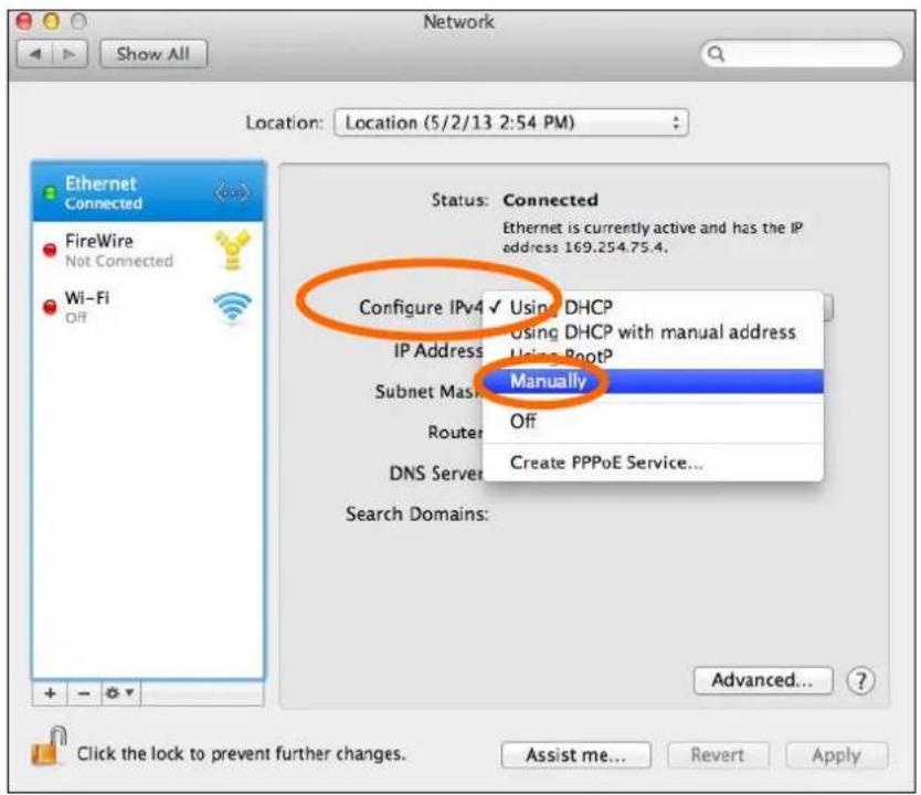
- Open the drop-down menu labeled "Congure IPv4" and select "Manually".
- Enter the IP address 192.168.2.10 and subnet mask 255.255.255.0. Click on "Apply" to save the changes.
V-1-6. Glossary
Default Gateway (Access point): Every non-access point IP device needs to congregate a default gateway's IP address. When the device sends out an IP packet, if the desnaon is not on the same network, the device has to send the packet to its default gateway, which will then send it out towards the desnaon.
DHCP: Dynamic Host Conguraon Protocol. This protocol automacally gives every computer on your home network an IP address.
DNS Server IP Address: DNS stands for Domain Name System, which allows Internet servers to have a domain name (such as www.Broadbandaccess point.com) and one or more IP addresses (such as 192.34.45.8). A DNS server keeps a database of Internet servers and their respective domain names and IP addresses, so that when a domain name is requested (as in typing "Broadbandaccess point.com" into your Internet browser), the user is sent to the proper IP address. The DNS server IP address used by the computers on your home network is the location of the DNS server your ISP has assigned to you.
DSL Modem: DSL stands for Digital Subscriber Line. A DSL modem uses your existing phone lines to transmit data at high speeds.
Ethernet: A standard for computer networks. Ethernet networks are connected by special cables and hubs, and move data around at up to 10/100 million bits per second (Mbps).
IP Address and Network (Subnet) Mask: IP stands for Internet Protocol. An IP address consists of a series of four numbers separated by periods that idenes a single, unique Internet computer host in an IP network. Example: 192.168.2.1. It consists of 2 porons: the IP network address, and the host idener.
The IP address is a 32-bit binary paern, which can be represented as four cascaded decimal numbers separated by “.”: aaa.aaa.aaa.aaa, where each “aaa” can be anything from 000 to 255, or as four cascaded binary numbers separated by “.”: bbbbbbbb.bbbbbbbb.bbbbbbbb.bbbbbbbb, where each “b” can either be 0 or 1.
A network mask is also a 32-bit binary paern, and consists of consecutive leading 1's followed by consecutive trailing 0's, such as 11111111.11111111.11111111.00000000. Therefore somemes a network mask can also be described simply as "x" number of leading 1's. When both are represented side by side in their binary forms, all bits in the IP address that correspond to 1's in the network mask become part of the IP network address, and the remaining bits correspond to the host ID.
For example, if the IP address for a device is, in its binary form, 11011001.10110000.10010000.00000111, and if its network mask is, 11111111.11111111.11110000.00000000 It means the device's network address is 11011001.10110000.10010000.00000000, and its host ID is, 00000000.00000000.00000000.00000111. This is a convenient and ecient method for access points to route IP packets to their desnaon.
ISP Gateway Address: (see ISP for denion). The ISP Gateway Address is an IP address for the Internet access point located at the ISP's oce.
ISP: Internet Service Provider. An ISP is a business that provides connectivity to the Internet for individuals and other businesses or organizaons.
LAN: Local Area Network. A LAN is a group of computers and devices connected together in a relatively small area (such as a house or an oce). Your home network is considered a LAN.
MAC Address: MAC stands for Media Access Control. A MAC address is the hardware address of a device connected to a network. The MAC address is a unique idener for a device with an Ethernet interface. It is comprised of two parts: 3 bytes of data that corresponds to the Manufacturer ID (unique for each manufacturer), plus 3 bytes that are oen used as the product's serial number.
NAT: Network Address Translaon. This process allows all of the computers on your home network to use one IP address. Using the broadband access point's NAT capability, you can access the Internet from any computer on your home network without having to purchase more IP addresses from your ISP.
Port: Network Clients (LAN PC) uses port numbers to disnguish one network applicaon/protocol over another. Below is a list of common applicaons and protocol/port numbers:
| Applicaon | Protocol | Port Number |
| Telnet | TCP | 23 |
| FTP | TCP | 21 |
| SMTP | TCP | 25 |
| POP3 | TCP | 110 |
| H.323 | TCP | 1720 |
| SNMP | UCP | 161 |
| SNMP Trap | UDP | 162 |
| HTTP | TCP | 80 |
| PPTP | TCP | 1723 |
| PC Anywhere | TCP | 5631 |
| PC Anywhere | UDP | 5632 |
Access point: An access point is an intelligent network device that forwards packets between dierent networks based on network layer address informaon such as IP addresses.
Subnet Mask: A subnet mask, which may be a part of the TCP/IP informaon provided by your ISP, is a set of four numbers (e.g. 255.255.255.0) congured like an IP address. It is used to create IP address numbers used only within a parcular network (as opposed to valid IP address numbers recognized by the Internet, which must be assigned by InterNIC).
TCP/IP, UDP: Transmission Control Protocol/Internet Protocol (TCP/IP) and Unreliable Datagram Protocol (UDP). TCP/IP is the standard protocol for data transmission over the Internet. Both TCP and UDP are transport layer protocol. TCP performs proper error detecon and error recovery, and thus is reliable. UDP on the other hand is not reliable. They both run on top of the IP (Internet Protocol), a network layer protocol.
WAN: Wide Area Network. A network that connects computers located in geographically separate areas (e.g. dierent buildings, cies, countries). The Internet is a wide area network.
Web-based management Graphical User Interface (GUI): Many devices support a graphical user interface that is based on the web browser. This means the user can use the familiar Netscape or Microso Internet Explorer to Control/congure or monitor the device being managed.
- FCC Compliance
- Copyright
- CONTENTS
- Product Informaon....6
- Quick Setup 11
- Hardware Installaon.... 18
- Browser Based Conguraon Interface.... 19
- Appendix 83
- Product Informaon
- I-1. Package Contents
- I-2. System Requirements
- I-3. Hardware Overview
- I-4. LED Status
- I-5. Reset
- I-6. Magnec Wall Mount
- I-7. Safety Informaon
- II-1. Inial Setup
- II-2. Basic Sengs
- II-3. Wi-Fi Protected Setup (WPS)
- Browser Based Conguraon Interface
- Use the menu across the top and down the le side to navigate.
- Click "Apply" to save changes and reload the access point, or "Cancel" to cancel changes.
- IV-1. Informaon
- IV-1-1. System Informaon
- System Information
- IV-1-2. Wireless Clients
- > Wireless Clients
- IV-1-3. Wireless Monitor
- > Wireless Monitor
- IV-1-4. Log
- When the log is full, old entries are overwritten.
- USB
- Wireless Client
- Authencaon
- Associaon
- WPS
- Change Sengs
- System Boot
- NTP Client
- Wired Link
- Proxy ARP
- Bridge
- SNMP
- HTTP
- HTTPS
- SSH
- Telnet
- WLAN (2.4G)
- WLAN (5G)
- ADT
- IV-2. Network Sengs
- IV-2-1. LAN-Side IP Address
- LAN-side IP Address
- IV-2-2. LAN Port
- IV-2-3. V L A N
- IV-3. Wireless Sengs
- IV-3-1. 2.4GHz 11bgn
- IV-3-1-1. Basic
- IV-3-1-2. Advanced
- Advanced
- IV-3-1-3. Security
- Security
- 2.4GHz Wireless Security Settings
- IV-3-1-3-1. No Authencaon
- IV-3-1-3-2. WEP
- IV-3-1-3-3. IEEE802.1x/EAP
- IV-3-1-3-4. WPA-PSK
- IV-3-1-3-5. WPA-EAP
- IV-3-1-3-6. Additional Authencaon
- MAC Address Filter
- MAC-RADIUS Authencaon
- MAC Filter & MAC-RADIUS Authencaon
- IV-3-1-4. WDS
- WDS
- 2.4GHz
- WDS Peer Settings
- WDS VLAN
- WDS Encryption method
- IV-3-2. 5GHz 11ac 11an
- IV-3-2-1. Basic
- IV-3-2-2. Advanced
- IV-3-2-3. Security
- IV-3-2-4. WDS
- 5GHz WDS Mode
- Encryption method
- IV-3-3. WPS
- WPS Security
- IV-3-4. RADIUS
- > RADIUS
- IV-3-4-1. RADIUS Sengs
- RADIUS Settings
- RADIUS Server (2.4GHz)
- IV-3-4-2. Internal Server
- IV-3-4-3. RADIUS Accounts
- Edit User Registraon List
- IV-3-5. MAC Filter
- IV-3-6. WMM
- WMM
- IV-4. Management
- IV-4-1. Admin
- IV-4-2. Date and Time
- IV-4-3. Syslog Server
- IV-4-4. I'm Here
- I'm Here
- The buzzer is loud!
- IV-5. Advanced
- IV-5-1. LED Sengs
- IV-5-2. Update Firmware
- Update Firmware
- IV-5-3. Save/Restore Sengs
- IV-5-4. Factory Default
- Factory Default
- IV-5-5. Reboot
- Reboot
- V-1. Conguring your IP address
- V-1-1. Windows XP
- V-1-2. Windows Vista
- V-1-3. Windows 7
- Click "Properes".
- V-1-4. Windows 8
- Right click "Network" and then select "Properes".
- In the window that opens, select "Change adapter setngs" from the le side.
- 5.
- Choose your conncon and right click, then select "Properes".
- Select "Internet Protocol Version 4 (TCP/IPv4) and then click "Properes".
- Select "Use the following IP address", then input the following values:
- IV-1-5. Mac
- V-1-6. Glossary
Brand : Comtrend
Model : WAP-PC1750W
Category : Access Point