
GCS1104 - Network switch IOGEAR - Free user manual and instructions
Find the device manual for free GCS1104 IOGEAR in PDF.


| Product Type | Network Switch |
| Brand | IOGEAR |
| Model | GCS1104 |
| Number of Ports | 4 |
| Port Speed | 10/100/1000 Mbps |
| Dimensions (L x W x H) | 5.3 x 3.7 x 1.1 inches (13.5 x 9.4 x 2.8 cm) |
| Weight | 0.5 lbs (0.23 kg) |
| Power Supply | External power adapter (5V DC, 1A) |
| Power Consumption | 2.5W (max) |
| Cooling | Passive (fanless) |
| LED Indicators | Power, Link/Activity per port |
| Mounting | Desktop or wall-mountable |
| Operating Temperature | 32°F to 104°F (0°C to 40°C) |
| Storage Temperature | -4°F to 158°F (-20°C to 70°C) |
| Humidity | 10% to 90% non-condensing |
| Safety Certifications | FCC, CE, RoHS |
| Warranty | 3 years |
| Package Contents | Switch, power adapter, user manual |
| Additional Features | Auto MDI/MDIX, jumbo frame support, flow control |
Frequently Asked Questions - GCS1104 IOGEAR
User questions about GCS1104 IOGEAR
0 question about this device. Answer the ones you know or ask your own.
Ask a new question about this device
Download the instructions for your Network switch in PDF format for free! Find your manual GCS1104 - IOGEAR and take your electronic device back in hand. On this page are published all the documents necessary for the use of your device. GCS1104 by IOGEAR.
USER MANUAL GCS1104 IOGEAR
DVI-D supported Monitor•
USB keyboard and mouse•
Powered Speakers and microphone (optional)•
Computers
A USB port •
A DVI-D supported connection•
3.5mm Audio and microphone connections (optional)
Operating System
Windows XP •
Windows Vista (32-bit/64-bit)
Windows 7•
Mac OS X or greater •
Sun Solaris workstation •
Linux, UNIX and other USB supported systems*
*Additional drivers and support may be needed
GCS1102 Overview
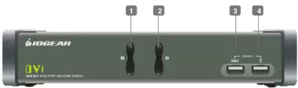
Front View
Port 1 Switch Button1.
Port 2 Switch Button2.
Console USB Keyboard Port3.
Console USB Mouse Port4.
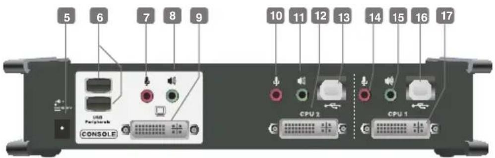
Rear View
Power Jack5.
USB 2.0 Peripheral Sharing Ports6.
Console Mic. Port7.
Console Audio Port8.
Console DVI Port9.
CPU2 Mic. Port10.
CPU2 Audio Port11.
CPU2 DVI Port12.
CPU2 USB Port13.
CPU1 Mic. Port14.
CPU1 Audio Port15.
CPU1 USB Port16.
CPU1 DVI Port17.
GCS1104 Overview
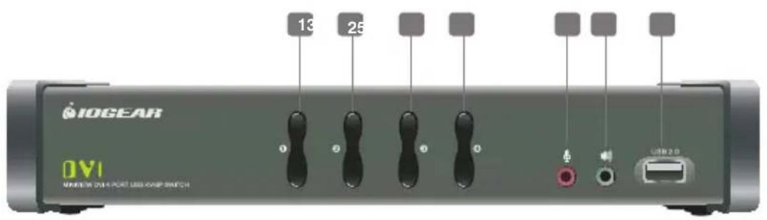
Front View
Port 1 Switch Button1.
Port 2 Switch Button2.
Port 3 Switch Button3.
Port 4 Switch Button4.
Front Panel Mic. Port5.
Front Panel Audio Port6.
USB 2.0 Peripheral Sharing Port 7.
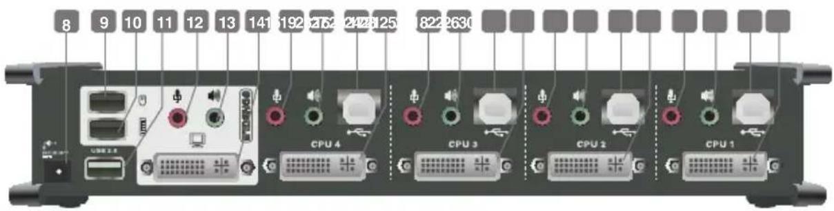
Rear View
Power Jack8.
Console Mouse Port9.
Console Keyboard Port10.
USB 2.0 Peripheral Sharing Port11.
Console Mic. Port12.
Console Audio Port13.
Console DVI Port14.
CPU4 Mic. Port15.
CPU4 Audio Port16.
CPU4 USB Port17.
CPU4 DVI Port 18.
CPU3 Mic. Port19.
CPU3 Audio Port20.
CPU3 USB Port21.
CPU3 DVI Port22.
CPU2 Mic. Port23.
CPU2 Audio Port24.
CPU2 USB Port25.
CPU2 DVI Port26.
CPU1 Mic. Port27.
CPU1 Audio Port28.
CPU1 USB Port29.
CPU1 DVI Port30.
Installation
Step 1
Please make sure your computers and monitor are powered off before you start.
Step 2
Connect the power adapter from your wall outlet to your power jack of the KVM.
Step 3
Connect the DVI cable from your monitor to the console DVI monitor port. Then, turn on your monitor.

Step 4
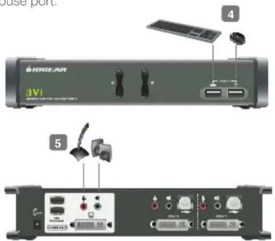
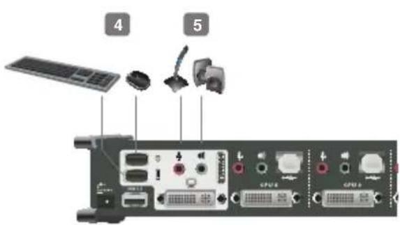
Connect your USB keyboard and mouse to the console USB keyboard port and console USB mouse port.
GCS1102
Step 5
Connect your powered speaker and mic. to the console audio port and console mic. Port.
GCS1104
Step 6
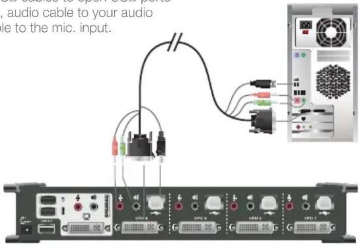
Connect a set of your molded KVM cable from your KVM switch to each of your computers – DVI cable to the DVI output, USB cables to open USB ports from your computer, audio cable to your audio output and mic. cable to the mic. input.
Final Step
Turn on your computers.
LED Indications
LED Description
Online / Selected Dim Orange A device is powered on and connected to the KVMP switch but the port is not on focus
Bright Orange The specific port has focus on the KVM (Keyboard, video and mouse)
USB Link Green The specific port has focus on the USB peripheral sharing ports
Port Switching
Port Switching
You can switch port via front panel pushbutton or hotkey commands.
Port Switching via Front Panel Pushbutton
Mode1 (Default)
Function Description
Switch All Focus (KVM, Audio and USB) Press and hold the specific pushbutton for 2 seconds
Switch KVM Focus Press the specific pushbutton once
Switch Audio Focus Press the specific pushbutton twice rapidly
Mode2*
Function Description
Switch All Focus (KVM, Audio and USB) Press the specific pushbutton once
Switch KVM Focus Press and hold the specific pushbutton for 2 seconds
Switch Audio Focus Press the specific pushbutton twice rapidly
*Please refer to the HSM (Hotkeys Setting Mode) section for details about how to switch the front panel pushbutton into Mode2.
Port Switching via Hotkey Commands
To trigger a Hotkey Mode, simply press [Scroll Lock] [Scroll Lock]*. Please refer to Hotkey Summary Table for details.
*Note: If there is a conflict using [Scroll Lock] [Scroll Lock] sequence, you can change to the alternative sequence [Ctrl] [Ctrl]. Please refer to Hotkey Setting Mode (HSM) section for details.
Hotkeys Summary Table
Hotkey combination Description
| [Scroll Lock] [Scroll Lock] + or[Ctrl] [Ctrl]* + | [Enter] Switch KVM, USB and audio focus to the next port |
| [n*] [Enter] Switch KVM, USB and audio focus to the specific port | |
| [k] [Enter] Switch KVM focus to the next port | |
| *Note: If alternative hotkey sequence is chosen | [n*] [k] [Enter] Switch KVM focus to the specific port |
| [u] [Enter] Switch USB focus to the next port | |
| [n*] [u] [Enter] Switch USB focus to the specific port | |
| [s] [Enter] Switch audio focus to the next port | |
| [n*] [s] [Enter] Switch audio focus to the specific port | |
| [n*] [k] [s] [Enter] Switch KVM and audio focus to the specific port | |
| [n*] [k] [u] [Enter] Switch KVM and USB focus to the specific port | |
| [n*] [u] [s] [Enter] Switch USB and audio focus to the specific port |
*Note: Interval n is the port ID number (1 and 2 for GCS1102 and 1, 2, 3 and 4 for GCS1104)
Autoscan Mode
You can either activate Autoscan Mode via front panel push button or hotkeys.
Function Description
Auto Scan Front Panel Push Button Press and hold port 1 and port 2 Pushbutton simultaneously for 2 seconds to activate Autoscan Mode*
| Hotkeys [Scroll Lock] [Scroll Lock] [a][Enter] | Activate Autoscan mode. It will cycle from port to port every 5 seconds (default) |
| [Scroll Lock] [Scroll Lock] [a][n] [Enter] | Activate Autoscan mode. It will cycle from port to port every n seconds** |
*Note: Autoscan Mode from front panel push button will be scanning a port every 5 seconds by default. If you wish to have the Autoscan Mode be scanning with different time interval, please trigger Autoscan Mode via hotkeys.
**Note: n is an interval between 1 and 99 that stands for the time (in second) desire for scanning each port.
Hotkey Setting Mode (HSM)
Hotkey Description
Press and hold [Num Lock] ([Clear] key 1. Invoking hotkey setting mode on Mac keyboard)
Press and release [-]2.
Release [Num Lock] ([Clear] key on 3.
Mac keyboard)
Invoke HSM, then press [h] Change the HSM invocation keys from [Num Lock] to [Ctrl] and from [-] to [F12]
Invoke HSM, then press [t] Change port switching hotkey sequence between [Scroll Lock] [Scroll Lock] and [Ctrl] [Ctrl]
Invoke HSM, then press [F2] Enables Mac keyboard emulation
Invoke HSM, then press [F3] Enables Sun keyboard emulation
Invoke HSM, then press [F10] Auto-detect the keyboard operating platform (for PC
compatible systems). Activates Pass Through Keyboard Mode (keystrokes are sent directly to the computer instead of through the Mac emulator).
Invoke HSM, then press [F4] List out current settings
Note: Please have a Notepad or word document opened before you trigger this function.
| Invoke HSM, then press [F5] USB Reset | |
| Invoke HSM, then press [b] Toggle hotkey beepers on or off | |
| Invoke HSM, then press [s] Toggle front panel pushbutton between Mode1 and Mode2 | |
| Invoke HSM, then press [x] [Enter] Disable or enable port switching hotkey | |
| Invoke HSM, then press [u] [p] [g] [r] [a] [d] [e] [Enter] | Activate Firmware Upgrade Mode – Front panel KVM LED will flash indicating Firmware Upgrade Mode is activated. |
| Invoke HSM, then press [r] [Enter] Restore default settings | |
| Invoke HSM, then press [d] Capture and store monitor's EDID on specific port | |
| Invoke HSM, then press [m] Enable or disable mouse emulation | |
| Invoke HSM, then press [F1] Reset keyboard and mouse under some special OS' that do not support USB 2.0 | |
*Note: To exit HSM manually, press Esc or spacebar.
Mac Keyboard Emulation
The PC compatible (101/104 key) keyboard can emulate the functions of the Mac keyboard. The emulation mappings are listed in the table below.
PC Keyboard Mac Keyboard
| [Shift] Shift | |
| [Ctrl] Ctrl | |
| ⌘ | |
| [Ctrl] [1] | |
| [Ctrl] [2] | |
| [Ctrl] [3] | |
| [Ctrl] [4] |
[Alt] Alt
| [Print Screen] F13 | |
| [Scroll Lock] F14 | |
| = | |
| [Enter] Return | |
| [Backspace] Delete | |
| [Insert] Help | |
| [Ctrl] |
*Note: When using key combinations, press and release the first key (Ctrl), then press and release the second key.
Sun Keyboard Emulation
The PC compatible (101/104 key) keyboard can emulate the functions of the Sun keyboard. The emulation mappings are listed in the table below.
PC Keyboard Sun Keyboard
| [Crtl] [t] Stop | |
| [Crtl] [F2] Again | |
| [Crtl] [F3] Props | |
| [Crtl] [F4] Undo | |
| [Crtl] [F5] Front | |
| [Crtl] [F6] Copy | |
| [Crtl] [F7] Open | |
| [Crtl] [F8] Paste |
[Ctrl] [F9] Find
| [Crtl] [F10] Cut | |
| [Crtl] [1] | |
| [Crtl] [2] | |
| [Crtl] [3] | |
| [Crtl] [4] | |
| [Crtl] [h] Help | |
| Compose | |
*Note: When using key combinations, press and release the first key (Ctrl), then press and release the second key.
Factory Default Hotkeys Settings
Function Default
Port Switching [Scroll Lock] [Scroll Lock]
Invoking HSM [Num Lock] [-]
Auto Scan Interval 5 Seconds
Beeper On
Keyboard Operating Platform Auto Detect
Port Switching Keys Enabled
Front Panel Pushbutton Mode Mode1
Mouse Emulation On
Firmware Upgrade
Step 1
Please follow through the installation process from the Installation section.
Step 2
Switch ALL focus to the port that you will be using to perform the firmware upgrade. (Please refer to Port Switching Section). Then, go to www.iogear.com to download the latest available firmware or the specific firmware that you wish to use.
Step 3
Shut down all the other computers that are connected to the KVM. Then Invoke Firmware Upgrade Mode. (Please refer to Hotkeys Setting Mode section)
Step 4
Disconnect your keyboard and mouse from the console keyboard and mouse port, then connect them to the USB peripheral sharing ports.
Step 5
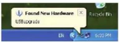
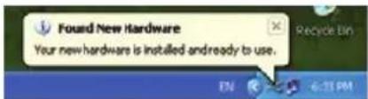
Windows will now install all the required drivers. You may see the below message popup in tray icon area.
Step 6
After you see the below message "Your new hardware is installed and ready to use.", extract the downloaded file with WinRAR or compatible software. Then double click on the execute file to begin with the Firmware Upgrade Utility.
Step 7
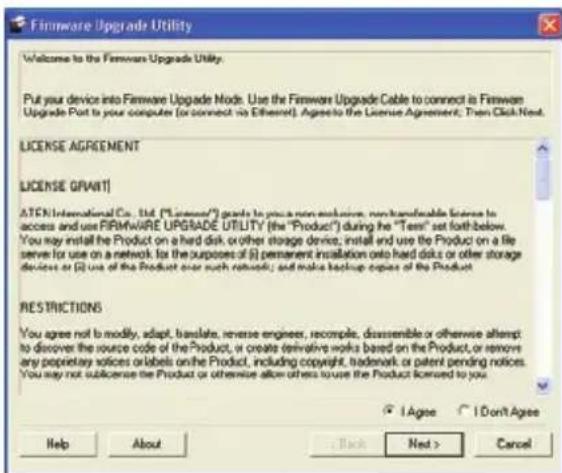
Read the License Agreement and click "I Agree" then click "Next" if you wish to continue with the firmware upgrade. Otherwise, click "Cancel" to exit.
Step 8
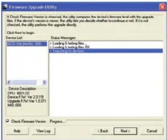
Choose the correct KVM that you wish to perform firmware upgrade from the "Device List" and then click "Next" to continue. Then the Firmware Upgrade Utility will verify if there is a KVM connected to the computer by the firmware upgrade cable. (Check Firmware Version checkbox is optional)
Step 9
If you have checked the "Check Firmware Version" checkbox, then the utility will check the current firmware that is on your KVM. If the current firmware is newer than the firmware that you wish to upgrade to, a window will popup and prompt you to ask if you wish to proceed. Simply click "Yes" to start the upgrade and "No" to cancel the upgrade.
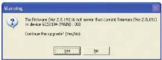
Note: If you did not check the "Check Firmware Version" checkbox, utility will perform the upgrade automatically no matter what version of firmware you have in the KVM.
Step 10
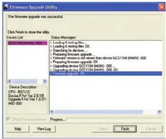
When the firmware upgrade is done, you will see "Firmware upgrade OK" in the "Status Messages" window. Then simply click "Finish" to complete the whole firmware upgrade process.
Final Step
Now the KVM will reset by itself and the firmware upgrade process has completed. Then, disconnect the keyboard and mouse from the peripheral sharing ports and connect them back to the console keyboard and mouse port.
Upgrade Fail
If you didn't see "Firmware upgrade OK" in the "Status Messages" window, it means that the firmware upgrade has failed. When that happens, please repeat the complete firmware upgrade process.
FAQ
What is the difference between DVI-A, DVI-D and DVI-I? 1.
DVI-A – The "A" stands for analog, which it supports analog DVI signal
DVI-D – The “D” stands for digital, which it supports digital DVI signal
DVI-I – The "I" stands for intergraded, which it supports both analog and digital DVI signals
If you have a DVI monitor with both DVI and VGA computers and you would like to connect 2. them through our GCS1102/GCS1104, what should you do and what do you need to know?
a. Please make sure that both monitor and monitor cable are DVI-I supported*
b. A VGA Male to Male cable for each of your VGA computer is required**
c. A VGA Female to DVI-A Male Adapter for each of your VGA computer is required***
*DVI-I Male to Male Cable (G2LDI006) is available and sold separately at www.iogar.com
**VGA Male to Male Cable (G2LVGA006) is available and sold separately at www.iogear.com.
***VGA Female to DVI-A Male Adapter (GDVIMVGAF) is available and sold separately at www.iogear.com.
If you meet all the requirements above, then you can follow the below instructions to setup your KVM. Please make sure all devices are turned off before you start.
For the DVI computers:
Simply follow the instruction of the Installation Section.
For the VGA computers:
Connect each of your VGA video output with a VGA Male to Male cable.1.
Connect the other side of the VGA cable to the VGA connection on the DVI-A Male to VGA Female 2. Adapter.
Connect the DVI-A connection to the CPU DVI port of the KVM.3.
Then use the provided DVI-D KVM cable for USB, audio and mic. connection ONLY.4.
For the Console DVI Port
Connect the DVI-I cable from the Console DVI port to the monitor.
FCC Statements
15.21
You are cautioned that changes or modifications not expressly approved by the part responsible for compliance could void the user's authority to operate the equipment.
15.105(b)
his equipment has been tested and found to comply with the limits for a Class B digital device, pursuant to part 15 of the FCC rules. These limits are designed to provide reasonable protection against harmful interference in a residential installation. This equipment generates, uses and can radiate radio frequency energy and, if not installed and used in accordance with the instructions, may cause harmful interference to radio communications. However, there is no guarantee that interference will not occur in a particular installation. If this equipment does cause harmful interference to radio or television reception, which can be determined by turning the equipment off and on, the user is encouraged to try to correct the interference by one or more of the following measures:
- Reorient or relocate the receiving antenna.
- Increase the separation between the equipment and receiver.
- Connect the equipment into an outlet on a circuit different from that to which the receiver is connected.
- Consult the dealer or an experienced radio/TV technician for help.
THIS DEVICE COMPLIES WITH PART 15 OF THE FCC RULES. OPERATION IS SUBJECT TO THE FOLLOWING TWO CONDITIONS:
- this device may not cause interference and
- this device must accept any interference, including interference that may cause undesired operation of the device.
FCC RF Radiation Exposure Statement:
This equipment complies with FCC radiation exposure limits set forth for an uncontrolled environment. End users must follow the specific operating instructions for satisfying RF exposure compliance. This transmitter must not be co-located or operating in conjunction with any other antenna or transmitter.
CE Statement
This device has been tested and found to comply with the requirements set up in the council directive on the approximation of the law of member states relating to EMC Directive 89/336/EEC, Low Voltage Directive 73/23/EEC and R&TTE Directive 99/5/EC.
The product has been approved for LVD and covered the following countries: Belgium, Denmark, France, Germany, Italy, Portugal, U.K., Spain, Sweden
SJ/T 11364-2006
The following contains information that relates to China.
The direct vendor makes no warranty or representation, expressed, implied, or statutory with respect to the contents or use of this documentation, and especially disclaims its quality, performance, merchantability, or fitness for any particular purpose. The direct vendor also reserves the right to revise or update the device or documentation without obligation to notify any individual or entity of such revisions, or updates. For further inquiries please contact IOGEAR.
Contact
IOGEAR
23 Hubble
Irvine, CA 92618
P 949.453.8782
F 949.453.8785
Visit us at: www.iogear.com

natural_image
Cartoon character with green leaf-like head and smiling expression (no text or symbols)About Us
FUN
IOGEAR offers connectivity solutions that are innovative, fun, and stylish, helping people enjoy daily life using our high technology products.
GREEN
IOGEAR is an environmentally conscious company that emphasizes the importance of conserving natural resources. The use of our technology solutions helps reduce electronic waste.
HEALTH
IOGEAR supports healthy and fit lifestyles. By integrating products with the latest scientific developments, IOGEAR's solutions enhance the life of end-users.
- Computers
- Operating System
- GCS1102 Overview
- Front View
- Rear View
- GCS1104 Overview
- Installation
- Step 1
- Step 2
- Step 3
- Step 4
- Step 5
- Step 6
- Final Step
- LED Indications
- Port Switching
- Port Switching via Front Panel Pushbutton
- Port Switching via Hotkey Commands
- Hotkeys Summary Table
- Autoscan Mode
- Hotkey Setting Mode (HSM)
- Mac Keyboard Emulation
- Sun Keyboard Emulation
- Factory Default Hotkeys Settings
- Firmware Upgrade
- Step 7
- Step 8
- Step 9
- Step 10
- Upgrade Fail
- FAQ
- What is the difference between DVI-A, DVI-D and DVI-I? 1.
- If you have a DVI monitor with both DVI and VGA computers and you would like to connect 2. them through our GCS1102/GCS1104, what should you do and what do you need to know?
- For the DVI computers:
- For the VGA computers:
- For the Console DVI Port
- FCC Statements
- CE Statement
- SJ/T 11364-2006
- Contact
- IOGEAR
- About Us
- FUN
- GREEN
- HEALTH
Brand : IOGEAR
Model : GCS1104
Category : Network switch