
LX10 - Tripod Libec - Free user manual and instructions
Find the device manual for free LX10 Libec in PDF.


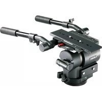
| Product Type | Fluid Head for Video Camera |
| Maximum Load Capacity | 16 kg (35.3 lb) |
| Pan Range | 360 degrees (continuous) |
| Tilt Range | +90° / -90° (approx.) |
| Pan Lock | Yes, lock knob |
| Tilt Lock | Yes, lock knob |
| Pan Drag Control | 2-level torque adjustment |
| Tilt Drag Control | 2-level torque adjustment |
| Bubble Level | Yes, built-in |
| Sliding Plate | Yes, with quick release and lock |
| Telescoping Pan Handle | Yes, adjustable length with clamp |
| Bowl Clamp | Yes, for leveling |
| Ball Leveler | Yes, adjustable |
| Camera Screw | 3/8" and 1/4" (spare 3/8" on platform) |
| Weight (approximate) | 2.5 kg (5.5 lb) |
| Dimensions (W x D x H) | 15 x 15 x 20 cm (6 x 6 x 8 in) |
| Material | Aluminum alloy |
| Maintenance | Wipe with a dry cloth; avoid liquids |
| Safety Warning | Do not exceed max load; firmly tighten all locks |
Frequently Asked Questions - LX10 Libec
User questions about LX10 Libec
0 question about this device. Answer the ones you know or ask your own.
Ask a new question about this device
Download the instructions for your Tripod in PDF format for free! Find your manual LX10 - Libec and take your electronic device back in hand. On this page are published all the documents necessary for the use of your device. LX10 by Libec.
USER MANUAL LX10 Libec
Fluid Head for Video Camera
摄像机云台
natural_image
Line drawing of a Libec camera with tripod base and lever handle (no text or symbols)アフターサービス
Libec Sales of America, Inc - U.S. Sales office
20695 S. Western Ave., #242, Torrance, CA 90501 USA
TEL:+1 310 787 9400
FAX:+1 310 787 9422
www.libecsales.com
J: 日本語
This equipment may cause harm, if not installed and used in accordance with this manual. Operating procedures and cautions to operate this product were written to prevent accident from occurring. For your own safety, read and follow these instructions before operating it. With adequate understanding, proper and safe operating manner can then be achieved. Please retain this manual for future references. This product has been designed with due consideration for safety. However, incorrect operation may cause camera to collapse, damaging of equipment and human injury. - Please read all the cautions and procedures before use. - Please follow all the cautions and safety contents that were written.
Caution
Injury may happen if the guidelines are not followed.
- Do not exceed the maximum capacity
The maximum load capacity is 16kg/35.3lb. Exceeding the load capacity may cause damage to equipment and unexpected accidents.
• Firmly tighten all locks, screws and clamp.
Failing to do so may cause damage to the camera
or injury to others.
- Mounting of camera on a proper positioned tripod
Mounting the camera on a improperly setup tripod may results in damages and injuries. - Do not dismantle or modify Dismantling and modifying the equipment may inflict injury to self and others, also are usually the root cause of accident.
Do not operate when the equipment is out of order, contact the dealer or our customer service for repairing.
Precaution before use
- Camera must be removed from the head after used and during relocation of site or transportation.
- Do not carry the pan handle during relocation.
- When tilting or panning, it is important to loosen the tilt or pan lock completely.
C: 中文

警告
A: 各部の名称
1 Head
2 Tilt lock
3 Sliding plate
4 Camera screw
5 Telescoping clamp
6 Pan handle clamp
7 Sliding plate lock
8 Tilt drag control
9 Pan handle
10 Plate release button
11 Pan drag control
12 Bubble level
13 Ball leveler
14 Bowl clamp
15 Pan lock
E
A: 部件名称

B: 三脚へ取り付ける
B: Mounting the head to the tripod
1 Loosen the bowl clamp and remove it from the head.
2 Set the head on to the tripod.
3 Hold the head, look into the bubble level and glide the ball leveler while controlling the bubble to stay at the center.
4 Firmly tighten the bowl clamp.
Leveling the head:
Pan handle position and length:
5 Loosen the pan handle clamp.
6 Set it to your most convenient position.
7 Firmly tighten the pan handle clamp.
8 Loosen the telescoping clamp.
9 Adjust the telescopic pan handle to your easy-to-use length.
10 Firmly tighten the telescoping clamp.
B: 连接于脚架
C: カメラを取り付ける
C: Mounting of the camera
- Firmly tighten the tilt lock when mounting or dismounting the camera. Also after the camera was mounted on the head, do not add accessories and others on it. With thehead suddenly tilt backward or forward, it may cause damage to the camera.
C-1 Removing the sliding plate:
1 Loosen the sliding plate lock.
2 Slide backwards the sliding plate while pressing the plate release button.
C-2 Attaching the sliding plate:
3 Set and tighten the camera screw of the sliding plate to the camera adapter plate.
※1 3/8" spare screw is installed on the platform as shown. Use these screws for additional reinforcement.
C-3 Attaching the camera to the head:
4 Loosen the sliding plate lock.
5 With the sliding plate mounted on the camera, slide in the same way as it was removed, push forward until it clicks.
- Do not secure the sliding plate lock yet.
•And not to press the plate release button.
6 To confirm the mounting was correct, hold the camera and slide towards the inserted entrance, to check that the camera does not come off the platform.
7 Slide the plate to the desired position and tighten the sliding plate lock.
C: 装配摄像机
D: スライドプレートを調整する
D: Adjusting of sliding plate
If the camera tilts to the backward or forward, adjustment is needed to shift the sliding plate front or behind.
•The head may tilt while adjusting the sliding plate. Keep hold of the camera to ensure it does not fall off.
1 Hold the camera and loosened the sliding plate lock.
2 Move the sliding plate front or back and find the position where the tilt balancing can be obtained, secure and tighten the sliding plate lock.
D: 调节滑板
E-2

natural_image
Line drawing of a video camera with tripod-mounted base and two labeled parts (3 and 4), no text or symbols present.E: パン・ティルトのトルク切替
E: Change torque for panning and tilting
You can choose from 2 different levels of torque for panning and tilting. Choose the level of torque depending on the type of filming to be done.
Do not adjust torque unless the pan lock knob or the tilt lock knob is fully loosened. Doing so may result in damage.
E-1 Change torque for panning
1 Use the pan torque knob to select desired level of torque.
2 Pan the camera to check the level of torque is correct.
E-2 Change torque for tilting
3 Use the tilt torque knob to select desired level of torque.
4 Tilt the camera to check that the amount of torque is correct.
E
E: 变换水平和俯仰的阻尼
F-2

J
F: Panning and Tilting
F-1 Panning
1,2 Release the pan lock for left and right movement.
3 Firmly tighten the pan lock, if locking is necessary.
F-2 Tilting
4,5 Release the tilt lock for up and down movement.
6 Firmly tighten the tilt lock, if locking is necessary.
C
F: 水平和俯仰以及锁定
F-1 水平

- Fluid Head for Video Camera
- アフターサービス
- J: 日本語
- Caution
- Precaution before use
- C: 中文
- 警告
- A: 各部の名称
- A: 部件名称
- B: 三脚へ取り付ける
- B: Mounting the head to the tripod
- Leveling the head:
- Pan handle position and length:
- B: 连接于脚架
- C: カメラを取り付ける
- C: Mounting of the camera
- C-1 Removing the sliding plate:
- C-2 Attaching the sliding plate:
- C-3 Attaching the camera to the head:
- C: 装配摄像机
- D: スライドプレートを調整する
- D: Adjusting of sliding plate
- D: 调节滑板
- E: パン・ティルトのトルク切替
- E: Change torque for panning and tilting
- E-1 Change torque for panning
- E-2 Change torque for tilting
- E: 变换水平和俯仰的阻尼
- F-2
- J
- F: Panning and Tilting
- F-1 Panning
- F-2 Tilting
- C
- F: 水平和俯仰以及锁定
- F-1 水平
Brand : Libec
Model : LX10
Category : Tripod