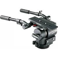
QH1 - Tripod Libec - Free user manual and instructions
Find the device manual for free QH1 Libec in PDF.


| Product Type | Tripod with Fluid Head |
| Brand | Libec |
| Model | QH1 |
| Maximum Height | 150 cm (approx.) |
| Minimum Height | 30 cm (approx.) |
| Folded Length | 60 cm (approx.) |
| Weight | 3.5 kg (approx.) |
| Payload Capacity | 5 kg (approx.) |
| Head Type | Fluid head with counterbalance |
| Leg Sections | 3 |
| Leg Material | Aluminum |
| Locking Mechanism | Flip-lock levers |
| Leveling Base | Bubble level integrated |
| Quick Release Plate | Included (standard Arca-Swiss compatible) |
| Handle | Pan handle included |
| Power Supply | None (manual operation) |
| Maintenance | Clean with dry cloth; avoid solvents |
| Safety | Do not exceed load capacity; secure legs on uneven ground |
| Spare Parts | Available from Libec or authorized dealers |
| Repairability | Repairable by qualified technicians; contact support |
| General Information | Designed for professional video and photography |
Frequently Asked Questions - QH1 Libec
User questions about QH1 Libec
0 question about this device. Answer the ones you know or ask your own.
Ask a new question about this device
Download the instructions for your Tripod in PDF format for free! Find your manual QH1 - Libec and take your electronic device back in hand. On this page are published all the documents necessary for the use of your device. QH1 by Libec.
USER MANUAL QH1 Libec
Fluid head for video camera
摄像机云台
natural_image
Technical line drawing of a mechanical device with cylindrical components and mounting brackets (no text or symbols)J: 日本語


E: English

WARNING
If not installed and used in accordance with this manual, this equipment may cause harm.
Operating procedures and cautions were written to prevent accident from occurring.
For your own safety, read and follow these instructions before operating it. With adequate understanding, proper and safe operations will be achieved. Please retain this manual for future references. This product has been designed with consideration for your safety. However, improper operations may cause camera equipment to collapse, which may result in damage to equipment and/or cause personal injury.
Caution
Injury may happen if the guidelines are not followed.
The maximum load capacity for QH1:40kg/88.2lb, QH3:69kg/152.1lb.
Exceeding the load capacity may cause damage to equipment and/or may cause personal injury.
please activate the Center Tilt Lock for safety.
Failing to do so may cause damage to the camera or injury to others.
Mounting the camera on a improperly setup tripod may results in damages and/or personal injuries.
Dismantling and modifying the equipment may inflict injury to self or others, and may lead to defects.
Do not operate when the equipment is out of order; contact the dealer or our customer service for repair.
Precaution before use
- Please remove the camera from the tripod head. Do not carry the tripod head with the camera attached.
- Do not hold the head by the pan handle during relocation.
- When tilting or panning, it is important to loosen the tilt or pan lock completely.
- When the head is not in use for a period of time, set the counterbalance to the minimum for storage.
C: 中文

警告
Es : Español

ADVERTENCIA


A:
L R
3/8-16 UNC
A: Part name A:
1 Head 1
2 Slide plate safety release lock 2
3 Quick release mechanism 3
4 Tilt lock 4
5 Tilt drag control 5
6 Pan drag control 6
7 Pan lock 7
8 Flat base 8
9 Level illumination switch 9
10 Bubble level 10
11 Counterbalance knob 11
12 Counterbalance meter 12
13 Pan handle (L, R) 13
14 Telescopic clamp 14
15 Pan handle clamp 15
16 Camera screw 16
17 Slide plate 17
18 Center Tilt Lock Icons 18
19 Center Tilt Lock 19
20 Spare camera screw 20
Screw hole (3/8-16 UNC)
21 Ball leveler 21
22 Ball leveler fixing screw 3/8" 22
23 Bowl clamp 23
B: Placing the tripod head.
Attaching a flat-base head
1 Secure the head with 4x 3/8" screws.
P1000.
Changing the flat-base configuration to a ball-base configuration
2 Remove the slide plate and place the head with the flat-base facing up.
3 Place the ball leveler on top of the flat base and match each hole.
4 Use the hexagon wrench to firmly attach the 4x 3/8" screws.
during usage.
Mounting the ball-base configuration head
5 Loosen the bowl clamp and remove it from the head.
6 Set the head on to the tripod.
Leveling the head
7 Hold the head, look at the bubble level and glide the ball leveler while keeping the bubble at the center.
about 10 to 15 sec, LED will cut off after this period or by pressing the switch again.
8 Firmly tighten the bowl clamp.
Adjusting the pan handle to the preferred length
9 Loosen the telescopic clamp.
10 Adjust the position
11 Adjust the length.
12 Lock the telescopic clamp.
B:
1
2
3
4
5
6
7
8
9
1
1
1
C: Panning and Tilting
Pannig
1,2 Release the pan lock for left and right movement.
3 Firmly tighten the pan lock, if locking is necessary.
Tilting
4.5 Relase the tilt lock for up and down movement.
6 Firmly tighten the tilt lock, if locking is necessary.
C:
7
2
3
4
5
6
D: Change torque for panning and tilting
You can choose from 7 different levels of torque for panning and tilting.
Choose the level of torque depending on the type of filming to be done.
Change torque for panning
1 Use the pan torque knob to select desired level of torque.
2 Pan the camera to check the level of torque is correct.
Change torque for tilting
3 Use the tilt torque knob to select desired level of torque.
4 Tilt the camera to check that the amount of torque is correct.
D:
1
2
3
4
natural_image
Technical line drawing of a mechanical assembly with no visible text or symbolsE:

3/8"

E: Mounting of the camera

please set the head with the following instructions.
strength to more than 50% in the counterbalance range
Removing the slide plate
1 Pull the quick release mechanism (1-2) and pull up the slide plate safety release lock (1-1) to unlock the slide plate.
2 Push down on the slide plate safety release lock (2-1) and remove the slide plate (2-2).
3 Set and tighten the camera screw of the slide plate to the camera adapter plate.
Attaching the slide plate
Use these screws for additional reinforcement.
Attaching the camera to the head
4 Activate the center tilt lock and secure the tilt lock knob.
5 Put the right side of the slide plate into the right side of the slide gap (5-1), and push down the left side of the slide plate until hearing a "click" sound (5-2).
6 After attaching the camera, hold the camera and check if the slide plate is securely on the head.
7 Slide the slide plate to a preferred position (7-1), and use the quick release mechanism to lock the slide plate firmly (7-2).
Activating and deactivating the center tilt lock
Activate
Deactivate


E:

1 2 3 4 5 6 7

F:

F:

1
(1-1)
1
2
2

F: Adjust the front-back balance
Adjust the front-back balance of the camera by adjusting the slide plate's position.
tilt and may cause damage to equipment and/or lead to personal injury.
1 While supporting the camera, pull up the slide plate release lever (1-1) and pull the quick release mechanism (1-2) to unlock the slide plate.
2 While supporting the camera, slide the camera with the slide plate to the front or back direction (2-1), and lock the slide plate when the camera is at a balanced position (2-2).
F: Ajustar el balance delantero-trasero
G:

G:

1
2
1
2
G: Adjusting the counterbalance
The counterbalance mechanism uses an inner spring to maintain the loaded camera to any still position no matter the direction or angle selected. Counterbalance tension can be adjusted by the counterbalance knob. Turning it clockwise increases the tension, counter clock-wise decreases the tension. Select the tension suitable for your needs.
1 Increase
2 Decrease
The position of the pointer: Up (Strong) > Down (Weak)
position and lock the center tilt lock. Keep holding the camera and check the front-back balance while adjusting the counterbalance.
G: Ajuste de contrapeso
H-2
5

natural_image
Technical line drawing of a mechanical device with gears and housing (no text or symbols)6
natural_image
Mechanical component diagram showing a curved housing with a downward arrow pointing to a small component (no text or symbols)7
8
9
natural_image
Diagram of a mechanical component with two arrows indicating direction, no text or symbols present10

natural_image
Diagram showing a mechanical component before and after assembly, with no visible text or symbols11

natural_image
Technical line drawing of a mechanical device with no visible text or symbolsH:
H-1
7
2
3
4
H-2
5
6
7
8
9
10
11

H:
H-1
1
2
3
4
H-2
5
6
7
8
9
10
11

H:Level illumination
H-1 Parts of level illumination
1 Level illumination holder
2 Level illumination switch
3 PCB unit
4 Battery
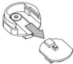
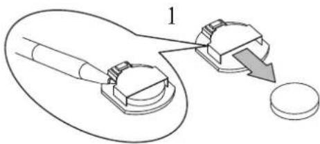
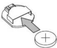
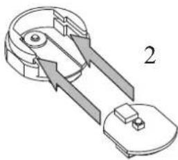
H-2 How to replace the battery (Using battery : CR1220)
5
Loosen and remove the level illumination holder.
6 Remove the PCB unit from the level illumination holder.
7 Turn over the PCB unit and remove the battery.
of the opening.
8 New battery with positive face up and insert into the opening.
9 Insert PCB unit into level illumination holder with the battery side face down.
holder and slide to the end.
10 Functional check by pressing the level illumination switch.
11 Ensure to tighten the level illumination holder.
Libec Sales of America, Inc - U.S. Sales office
TEL:+1 310 787 9400
Libec Asia Pacific Pte. Ltd. - Singapore office
TEL:+65 6296 9930


- Fluid head for video camera
- 摄像机云台
- J: 日本語
- E: English
- WARNING
- Caution
- Precaution before use
- C: 中文
- Es : Español
- ADVERTENCIA
- A:
- A: Part name A:
- B: Placing the tripod head.
- B:
- C: Panning and Tilting
- D: Change torque for panning and tilting
- E:
- E: Mounting of the camera
- Removing the slide plate
- Attaching the slide plate
- Attaching the camera to the head
- F:
- F: Adjust the front-back balance
- F: Ajustar el balance delantero-trasero
- G:
- G: Adjusting the counterbalance
- G: Ajuste de contrapeso
- H:
- H:Level illumination
Brand : Libec
Model : QH1
Category : Tripod