Highwire PowerStar - Powerline Adapter Veracity - Free user manual and instructions
Find the device manual for free Highwire PowerStar Veracity in PDF.


| Product Type | Ethernet over Coax (EoC) Adapter with LINKLOCK Security |
| Brand | Veracity |
| Model | Highwire PowerStar Base 8 LINKLOCK (VHW-HWPS-B8-LL) |
| Number of Channels | 8 tamper-proof channels |
| Coax Connector | BNC 75 Ohm x 8 |
| Ethernet Connector | RJ45 Gigabit (1000Base-TX) with optional SFP socket |
| LINKLOCK Feature | Yes – tamper detection disconnects power and data |
| Maximum Range | Up to 300m (1000ft) on RG59; 500m (1640ft) on RG11 |
| Bandwidth | 200 Mbps total (up + down) per channel |
| Power Input | 57V DC, up to 6A (detachable screw terminal or Micro-Fit connector) |
| Power Consumption | 10W (idle) to 20W (full PoE load) |
| PoE Output | IEEE 802.3af (PoE) or 802.3at (PoE+), up to 25W per channel |
| Alarm Output | Relay contact (NO, COM, NC) on screw terminal |
| Reset Method | Physical reset pins on screw terminal connector |
| Dimensions (L x W x H) | 173mm x 110mm x 40mm (including BNC connectors) |
| Weight | 572g (20.2 oz) |
| Operating Temperature | 0°C to 40°C (32°F to 104°F) |
| Relative Humidity | 85% non-condensing |
| Compliance | FCC, CE, RoHS, REACH |
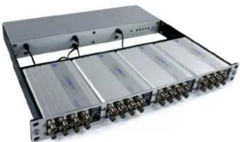
| Mounting | Can be rack-mounted in 19" rack (up to 4 units in 1U with PSU) |
| Maintenance & Cleaning | Clean the exterior with a soft, dry cloth. Do not use liquid cleaners. |
| Safety Precautions | Use only the provided power supply. Do not expose to moisture. Ensure proper ventilation. |
| Spare Parts & Repairability | Replacement power supplies and coax cables are available. No user-serviceable internal parts. |
Frequently Asked Questions - Highwire PowerStar Veracity
User questions about Highwire PowerStar Veracity
0 question about this device. Answer the ones you know or ask your own.
Ask a new question about this device
Download the instructions for your Powerline Adapter in PDF format for free! Find your manual Highwire PowerStar - Veracity and take your electronic device back in hand. On this page are published all the documents necessary for the use of your device. Highwire PowerStar by Veracity.
USER MANUAL Highwire PowerStar Veracity
TAMPER-PROOF ETHERNET & POE OVER COAX
HIGHWIRE™
BASE 8
LINKLOCK

natural_image
Two professionals in a data center discussing with laptops and a satellite (no visible text or symbols)HIGHWIRE Powerstar Base 8 LINKLOCK can be 19" rack-mounted
LINKLOCK™ technology provides secure tamper-proof network connections over coax cable
LINKLOCK options are available in Veracity's high performance HIGHWIRE Powerstar Base 4 and Base 8 Ethernet and POE over coax devices.
| Tamper-proof Ethernet a nd POE over coax
| 8 tamper-proo f channels per Base unit
Tampering or interference with cabling shuts down channel
Relay contact alarm output on tamper, with reset pins
| 32 POE or POE Plus channels in 1U with four Base units
| Automatic configuration for simple installation
Full duplex 100Base-TX performance on each coax
LINKLOCK™ provides a secure barrier to unauthorised access to your network
LINKLOCK™ detects any disconnection/reconnection or tampering with any part of the cabling between the Base unit and the IP camera or other POE device.
When Is LINKLOCK Required?
Any externally mounted IP cameras potentially leave an exposed network connection which could be used by attackers to access the rest of the network - to disable the surveillance system for example. This may also expose the corporate network as this is often bridged to the surveillance network. LINKLOCK prevents such attacks by completely disconnecting power and data for that channel whenever it detects a cable disconnection or reconnection or even any tampering such as "tapping in" to the coax or network cables.
How Does LINKLOCK Work?
LINKLOCK works by constantly monitoring the POE power connection and data transmissions. It can detect even subtle changes or interruptions in the data transmission characteristics which will trigger disconnection and alarm, whilst remaining extremely robust against false alarms.
Once triggered and disconnected, the channel can be re-established via the reset pins after suitable action is taken to determine the cause of the alarm (i.e. a possible attacker).
HIGHWIRE Powerstar Base LINKLOCK Option
LINKLOCK™ is available as an option on Veracity's HIGHWIRE Powerstar Base 4 and Base 8 models of Ethernet and POE over coax adaptors.
The Base unit accepts external power via a POE switch or a DC power supply. It sends power over the coax link to the Camera unit. The camera unit in turn provides POE (Power-over-Ethernet) to the IP camera.
See HIGHWIRE Powerstar Base 4 or Base 8 datasheets for full information on HIGHWIRE.
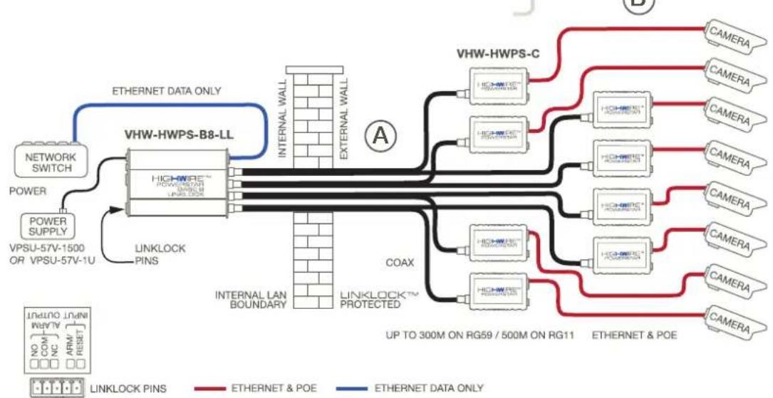
HIGHWIRE POWERSTAR BASE 8 with LINKLOCK Connection Diagram
flowchart
graph TD
    A["NETWORK SWITCH"] --> B["POWER"]
    B --> C["POWER SUPPLY"]
    C --> D["VPSU-57V-1500 OR VPSU-57V-1U"]
    D --> E["VHW-HWPS-B8-LL"]
    E --> F["INTERNAL LAN BOUNDARY"]
    F --> G["COAX"]
    G --> H["LINKLOCK™ PROTECTED"]
    H --> I["HIGH-WHPS-C"]
    I --> J["CAMERA"]
    I --> K["CAMERA"]
    I --> L["CAMERA"]
    I --> M["CAMERA"]
    I --> N["CAMERA"]
    I --> O["CAMERA"]
    I --> P["CAMERA"]
    style A fill:#f9f,stroke:#333
    style B fill:#ccf,stroke:#333
    style C fill:#cfc,stroke:#333
    style D fill:#fcc,stroke:#333
    style E fill:#cff,stroke:#333
    style F fill:#ffc,stroke:#333
    style G fill:#cfc,stroke:#333
    style H fill:#fcc,stroke:#333
    style I fill:#ffc,stroke:#333
    style J fill:#cfc,stroke:#333
    style K fill:#cfc,stroke:#333
    style L fill:#cfc,stroke:#333
    style M fill:#cfc,stroke:#333
    style N fill:#cfc,stroke:#333
    style O fill:#cfc,stroke:#333
    style P fill:#cfc,stroke:#333
natural_image
Front view of a rack-mounted server rack with multiple drive bays and connectors (no visible text or labels)Rackmount | Four rack-mounted HIGHWIRE Powerstar Base 8 Linklock units assembled with a Veracity 1U PSU.
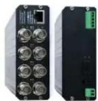
Front | 8 coax links with status LEDs, plus a Gigabit uplink port.
Rear | Power connectors (screw terminal or micro-fit) with SFP socket for fibre module and LINKLOCK Pins
LINKLOCK Protection
LINKLOCK provides protection to both the coaxial cable and the Ethernet cable connecting the IP camera to the HIGHWIRE Camera unit (sections A and B in the diagram opposite).
LINKLOCK disconnection (blocking mode) is triggered when:
• The coaxial cable A is disconnected
• The Ethernet cable B is disconnected
• The coaxial cable A is disrupted
• The Ethernet cable B is disrupted
Note that having a secure or encrypted link over the coax alone does not prevent intrusion as the Ethernet link to the camera would still be open and unsecured without LINKLOCK.
When blocking mode is enabled, all external equipment is immediately isolated from the internal LAN.
The internally-located HIGHWIRE Powerstar Base 4 or 8 unit will :
- Remove POE Power from the coaxial cable (this disconnects and switches off the HIGHWIRE Camera unit and IP camera).
• Completely disable its coaxial network interface for the triggered channel only. - Close the alarm relay contact and indicate the alarm channel with a red LED.
Restoring the Connection
LINKLOCK blocking mode is constant until reset. For complete security it cannot be reversed through the external network or coaxial interface. The HIGHWIRE LINKLOCK Base unit must be physically reset through the reset pins on the alarm interface connections. A push-button or relay is normally wired to the reset pins. If desired, network-controlled relay devices may be used to allow remote reset from any secure part of the network.
Typically, the camera disconnection would be used to trigger an alarm within the VMS (Video Management System) or NVR (Network Video Recorder).
TECHNICAL SPECIFICATION
HIGHWIRE™
BASE 8
LINKLOCK
HIGHWIRE INTERFACE
Connector type BNC 75 Ohm x 8
Cable type Any 75 Ohm coaxial (other impedances supported)
Range Up to 300m [1000ft] on RG59 or 500 metres [1640 feet] on RG11 at full rate
Bandwidth 200 Mbps (total up + down) x 8
ETHERNET INTERFACE
Connector type RJ45 with optional SFP socket for fibre
Cable type Cat 5/6 Patch or crossover, auto-detected or as per optional SFP device
Rate Gigabit Ethernet, Full duplex (1000Base-TX) with auto-negotiation
LINKLOCK INTERFACE
LINKLOCK Trigger On disconnection or tamper of coax or network cable
LINKLOCK Alarm Relay switch output (NO, COM, NC) on screw terminals connector
LINKLOCK Reset Via reset pins on screw terminals connector
Connector 5-pin removable screw terminal connector
LEDS
Status indicators HIGHWIRE coax link - flashes red when LINKLOCK is triggered
Ethernet link/activity (BASE) - flashes red when LINKLOCK is triggered
See Quickstart Guide for LED indicator table and diagnostics. Guide also online
POWER
Unit power 10W rising to 20W under full POE load
POE Out IEEE 802.3af (POE) or IEEE 802.3at (POE Plus) up to 25W per channel
Power input 57V DC, up to 6A via a 2 pin detachable screw terminal (supplied)
or a 2 pin Micro-Fit power connector
PHYSICAL/ENVIRONMENTAL
Dimensions L 173mm (including BNC connectors) W 110mm H40mm
Weight 572g [20.2oz]
Operating temperature 0°C to 40°C [32°F to 104°F]
Relative humidity 85% non-condensing
Compliance FCC, CE, RoHS, REACH
PRODUCT CODES
VHW-HWPS-B8-LL HIGHWIRE Powerstar Base 8 LINKLOCK™ eight channel unit with LINKLOCK
VHW-HWPS-B4-LL HIGHWIRE Powerstar Base 4 LINKLOCK™ - four channel unit with LINKLOCK
VHW-HWPS-C HIGHWIRE Powerstar™ Camera - single channel EOC adaptor for camera end
VPSU-57V-1500 57V DC, 1500mA (80W max) power supply
VPSU-57V-1U-UK 57V DC, 8800mA (400W max) power supply, with cable for UK
VPSU-57V-1U-EU 57V DC, 8800mA (400W max) power supply, with cable for EU
VPSU-57V-1U-US 57V DC, 8800mA (350W max) power supply, with cable for US
Only the Base unit requires the
LINKLOCK feature. These are
used with standard Camera units.

veracity
- LINKLOCK™ technology provides secure tamper-proof network connections over coax cable
- LINKLOCK™ provides a secure barrier to unauthorised access to your network
- When Is LINKLOCK Required?
- How Does LINKLOCK Work?
- HIGHWIRE Powerstar Base LINKLOCK Option
- LINKLOCK Protection
- Restoring the Connection
- TECHNICAL SPECIFICATION
- HIGHWIRE INTERFACE
- ETHERNET INTERFACE
- LINKLOCK INTERFACE
- LEDS
- POWER
- PHYSICAL/ENVIRONMENTAL
- PRODUCT CODES
Brand : Veracity
Model : Highwire PowerStar
Category : Powerline Adapter