
A2E4P - Access Control System Speco Technologies - Free user manual and instructions
Find the device manual for free A2E4P Speco Technologies in PDF.


| Product Type | Access Control System |
| Model | A2E4P |
| Brand | Speco Technologies |
| Dimensions | 12.5 x 8.0 x 2.5 cm |
| Weight | 0.5 kg |
| Power Supply | 12V DC, 2A |
| Current Consumption | 500 mA max |
| Supported Users | Up to 2000 |
| Authentication Methods | Keypad PIN, RFID card, or fingerprint (optional) |
| Relay Output | 1 relay, 5A/30VDC |
| Communication Interface | Wiegand 26-bit, RS485 |
| Operating Temperature | -10°C to 50°C |
| Environmental Rating | IP20 (indoor use only) |
| Main Functions | Door lock control, user management, audit trail, anti-passback, timed unlock |
| Maintenance | Clean with a dry cloth; check wiring connections monthly |
| Safety Features | Overload protection, tamper alarm, emergency unlock input |
| Spare Parts & Repairability | Power supply, keypad, reader board available; field-replaceable units |
| General Information | Standalone or networkable; easy installation with mounting template |
Frequently Asked Questions - A2E4P Speco Technologies
User questions about A2E4P Speco Technologies
0 question about this device. Answer the ones you know or ask your own.
Ask a new question about this device
Download the instructions for your Access Control System in PDF format for free! Find your manual A2E4P - Speco Technologies and take your electronic device back in hand. On this page are published all the documents necessary for the use of your device. A2E4P by Speco Technologies.
USER MANUAL A2E4P Speco Technologies
Speco Access Control System Installation Instructions
for 2 & 4 Door Systems with Integrated Power Supplies

natural_image
Interior view of an open black electrical control cabinet with internal components and wiring (no visible text or symbols)speco technologies Giving You More.
Table of Contents
Notifications....3
Copyright....3
Approvals....3
Notice....3
Introduction....4
Access Control Overview....4
System Overview....4
2 & 4 Door Systems Specifications....5
Installation of 2 & 4 Door Systems....6
Installation Check List....6
Locating the Controller for Installation....6
Mounting the Metal Enclosure - 2 & 4 Door Systems....7
Tamper Detection....8
System Power....8
Power Fault Detection....8
Door Lock Power....8
Fire Release Input....9
Battery Connection....9
Battery Warnings....9
Input Power Connector....10
Controller Power, Power Fault and Fire Cutout Connector....10
Output Power Connectors....11
Power Connection....12
Calculating Estimated Standby Time....12
Controller Features - 2 & 4 Door Systems....13
Controller Hardware Identification....13
Controller Inputs....13
Controller Connectors....14
Input Wiring....14
Request to Exit and Door Position Connectors....15
Power, Power Fault and Tamper Connector....16
Controller Outputs....19
Output Wiring Requirements....20
Door and Auxiliary Output Connectors....20
Adding 2 Door Expansion....22
Powering On and Connecting to a Network....23
Preparing for the Network....23
Connecting to the Local Network....24
Adding Clients to Systems....25
IP Installer....26
System Configuration and Programming....27
Trouble Shooting....28
Testing, Maintenance and Service....30
Parts List....30
Contact & Warranty Information....31
Notifications
Copyright
Copyright © 2019, all rights reserved. No part of this document may be reproduced, copied, adapted or transmitted in any form without written permission from Speco Technologies.
Approvals
This equipment has been tested and found to comply with the limits for a Class A digital device, pursuant to part 15 of the FCC Rules. These limits are designed to provide reasonable protection against harmful interference when the equipment is operated in a commercial environment. This equipment generates and can radiate radio frequency energy and if not installed and used in accordance with the manual, may cause harmful interference. Operation of this equipment in a residential area is likely to cause harmful interference in which case the user will be required to correct the interference at their own expense.
This Access Control System is compliant with Level I UL 294 listed devices and must be installed in a secure, controlled location.
Notice
This manual contains information regarding the basic installation and configuration of the browser-based Access Control System. It must be read and completely understood before installation or operation.
It is intended that this unit will be installed by persons trained and qualified to install access control systems and has the skills and knowledge working with electrical circuits and safety codes. Important safeguards and instructions in this manual cannot cover all possible situations and conditions that occur during installation and use and it must be understood that common sense and caution must be exercised by the person(s) installing, maintaining and operating the equipment.
Installations must conform to all national and local building and electrical codes.
This manual is for installing 2 & 4 Door Systems with integrated power; Models A2E4, A2E4P, A4 and A4P.
Introduction
Access Control Overview
Access Control is the selective restriction to a place or resource such as a property, building or room to authorized persons and is a matter of who, where, and when. An access control system is used to automate access control using credentials, credential readers, electric door locks and other devices. Administrators configure the system to determine who is allowed to enter or exit, where they are allowed to exit or enter, and when they are allowed to enter or exit. When access is granted, the door is unlocked for a predetermined time and transaction is recorded. When access is denied, the door remains locked and the attempted access is recorded. Administrators can then run reports on the recorded transactions to review activity for selected dates and times.
System Overview
Controller models are available in variety of configurations starting from 1 Door models that require a separate power supply to 2 & 4 Door models that include an integrated power supply for the controller and door lock power. Most models can be ungraded after installation with enhanced features, such as enhanced reporting or more users, using software license keys. All controllers include tamper and power fault inputs, in and out readers, request to exit and door position inputs for each door and auxiliary inputs and outputs. All controllers are designed to be connected to a network using an Ethernet RJ45 connector and configured using the integrated web server.
Controllers can be configured as either a server or a client. All systems require a server controller. Some systems have the ability to add additional client controllers to increase the number of doors, inputs or outputs or control elevators. The software license key is used by the controller to determine if it is a server or a client. After logging in, the license information about a can be determined by clicking on the license icon at the bottom of the web page.
Certain models offer a mobile APP that can be used to setup and configure, view logs, lock and unlock doors and activate threat levels. In addition, some systems also offers a cloud service that provides a portal where a users or dealer can log into and manage one or many systems securely.
Client controllers communicate with the server controller via the local area network and are configured through the server using a web browser on PC connected to the network. Once the server or client controller is configured, they will function without a network connection or the PC. The network and PC is only required for setup, configuration and reporting.
2 & 4 Door Systems Specifications
| General Specifications | |
| Processor Quad Core Cortex, 1.5 GHz | |
| Memory 1GB DDR3 & 8 GB eMMc | |
| Operating System Embedded Linux | |
| Transactions > 45 per Second | |
| System Power Requirements 115VAC @ 1.5A | |
| Operating Temperature 50°F to 95°F (10°C to 35°C) | |
| Enclosure Size (W x H x D) 14.25 x 14.25 x 3.75 in ( 362 x 362 x 95 mm) | |
| Model | 2 Door Systems 4 Door Systems | |||
| A2E4 A2E4P A4 A4P | ||||
| Internal Power Supply | Controller & Readers Only | Controller, Readers & 12V and 24V DC for Door Locks | Controller & Readers Only | Controller, Readers & 12V and 24V DC for Door Locks |
| Lock Power Output NA | 375 mA @ 24V 700 mA @ 12V | NA | 375 mA @ 24V 700 mA @ 12V | |
| Battery Backup | Controller & Readers Only | Controller, Readers & Door Lock | Controller & Readers Only | Controller, Readers & Door Lock |
| Recommended Battery Type (battery is not included) | Powersonic PS-1270-FI or Similar 12V, 7AH, Sealed Lead Acid with 0.187 inch terminals | |||
| Standby Power Requirement | 400 mA @ 12V | 450 mA @ 12V | 500 mA @ 12V | 550 mA @12V |
| Readers (Wiegand) | 4 Total, One In & One Out Reader for Each Door | 8 Total, One In & One Out Reader for Each Door | ||
| Reader Power | 300 mA @ 12V Max per Reader 1000 mA @ 12V Max per System | 300 mA @ 12V Max per Reader 1500 mA @ 12V Max per System | ||
| Request to Exit (REX) Inputs | 2 Total, One for Each Door | 4 Total, One for Each Door | ||
| Door Position (status) Inputs | 2 Total, One for Each Door | 4 Total, One for Each Door | ||
| Auxiliary Inputs 2 Total, General Purpose | 4 Total, General Purpose | |||
| Tamper Digital Input | Yes, Prewired on Units with Integrated Power | |||
| Power Fault Digital Input | Yes, Prewired on Units with Integrated Power | |||
| Door Lock Outputs | 2 Form C Relay, 24V @ 2.0A | 4 Form C Relay, 24V @ 2.0A | ||
| Auxiliary Outputs | 2 Form C Relay, 24V @ 2.0A | 4 Form C Relay, 24V @ 2.0A | ||
| UL294 7th Edition Rating | ||||
| Destructive Attack | Line Security | Endurance | Standby Power | Single Point Locking Device with Key Locks |
| Level I | Level I | Level IV | Level I | Level I |
Installation of 2 & 4 Door Systems
Installation Check List
The list below provides a logical sequence for installing a system. This list cannot cover all possible situations and conditions that occur during installation and use and it must be understood that common sense and caution must be exercised by the person(s) installing, maintaining and operating the equipment.
√Calculate the systems power requirement by adding up the power required for each device connected to the system to make sure the required power can be provided by the system.
√Mount the controller in a secure, controlled location
√Connect the inputs and outputs
√Connect the readers
√Connect the door locks and auxiliary outputs
√Connect power to the controller using a dedicated unswitched, grounded outlet rated for 115 VAC @ 5 Amps
√Obtain an IP address, Subnet Mask, DNS and other information from the network administrator
√Configure the controller's network settings
√Connect the controller to the local area network
√Add optional license keys to upgrade features
Locating the Controller for Installation
Choose a centrally located, secure, clean and dry area near an AC power source. Avoid mounting the controller within 6 feet of any equipment that may generate electrical interference.
NOTICE: The power supply used for the controller must only be connected to an unswitched, grounded, 115 VAC outlet. If an unswitched outlet is not available or within 6 feet of the controller mounting location, have a licensed electrician install an outlet per local codes. All wiring must be in accordance with the National Electrical Code, NPFA 70 and all local codes. For UL installations, the maximum Ethernet cable length is 98.5 feet (30 meters).
NOTE: This device complies with Part 15 of the FCC Rules. Operation is subject to the following two conditions: (1) this device may not cause harmful interference and (2) this device must accept any interference received, including interference that may cause undesired operation.
Mounting the Metal Enclosure – 2 & 4 Door Systems
The metal enclosure should be mounted vertically on a wall in a secure location. The temperature in the mounting location must be within the system's specified limits. A minimum of 8 inches of space around all sides of the enclosure is recommended. Knockouts are provided along the sides and top of the enclosure for routing wires. When running wires through the knockouts, install bushings or conduit connectors as needed to protect wires from damage.
- Run all wires to the enclosure location and label the wires according to their use.
- Remove the enclosure's door by first unlocking the door and removing the door's ground wire. The door may be lifted out of the hinge slots, which will provide room for mounting and connecting wires to terminals.
- Locate the enclosure on the wall and level. Mark the mounting holes on the wall and remove the enclosure and install anchors appropriate for the type of wall and mounting conditions. The mounting slots are sized for use with 14 inch hex head lag screws. Use a length suitable for the mounting conditions but typically not less than 134 inch long.
- DO NOT DRILL the mounting holes while the enclosure is in place on the wall. Dust and debris from drilling will contaminate and damage the electronics.
- Partially insert mounting screws into the top two mounting holes and hang the enclosure on the screws. Check for level, insert the lower screws and tighten all four mounting screws.
- Run the wires through the knockout holes and connect to the appropriate terminals (see following sections of the manual for wiring details). Note: Tie down loops are located in the enclosure and are used to provide strain relief for field wiring connections to the controller.
- Reinstall the door and reconnect the door's ground wire.
NOTICE: This equipment includes electronic components that are sensitive to static electricity. Make sure to discharge by touching an earth ground before handling this equipment.
NOTE: When locating the controller, choose a centrally located, secure, clean and dry area. Avoid mounting the controller within 6 fee (2 meters) of any equipment that generates electrical interference.
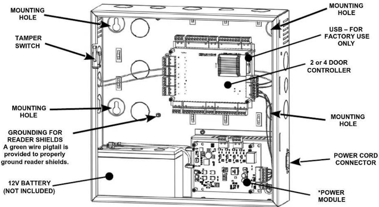
2 & 4 Door System Features and Mounting Locations (*There are two types of power modules, one with lock power and one without)
Tamper Detection
A tamper switch is mounted in the enclosure and is prewired to the controller. If the enclosure's door is opened, the tamper switch will activate and signal the controller. The controller can be configured using Event Actions to perform a system backup, activate an auxiliary output or send an email notification when a tamper input is detected.
System Power
The enclosure includes a 12 VDC 6 Amp (75W) power supply and Power Module. The power module provides power to charge a 12V sealed lead acid battery (SLA, not included) that is used for battery backup operation, power for door locks and power for the main controller and accessories such as readers and keypads. NOTE: A indicator light on the exterior of the enclosure is illuminated when the system is plugged in and AC power is present.
Power Fault Detection
When the power power module detects an AC power loss, it will automatically change operation over to battery backup and signals the controller that a power fault has occurred. The controller's fault input can be configured using Event Actions to perform a system backup, activate an auxiliary output or send an email notification. This is prewired at the factory.
Door Lock Power
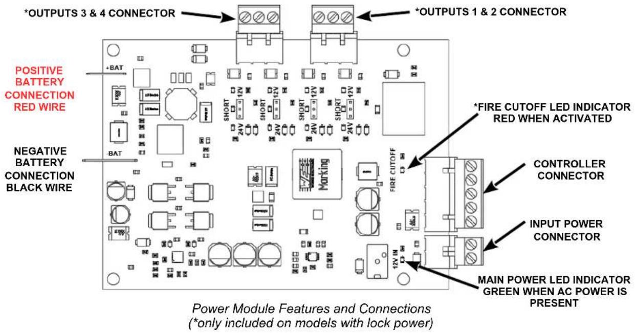
On models that include power for the door locks, the power module has the ability to supply either 12 or 24 VDC power to the door locks. This can be set individually for each of the four outputs. LED's indicate if the output power is set to 12 VDC (GREEN LED), 24 VDC (AMBER LED) or if the output is overloaded (RED LED). NOTE: The maximum output current for each of the four outputs is 375 mA @ 24V or 700 mA @ 12V.
Fire Release Input
On models that include power for the door locks, the power module is prewired with a normally closed Fire Release input. If the input is opened, power will be disconnected from the connected door locks. This can be used to unlock fail safe door locks. Note: The power module and/or access control system is not listed as and can not be used as a fire warning system.
Battery Connection
The enclosure provides space and charging for one 12V sealed lead acid battery. The power module monitors the battery to prevent over charging and excessive discharging. When primary AC power is lost, the battery will provide standby power until the battery voltage reaches approximately 11 VDC at which point the system will shutdown until main power is restored. The amount of time standby power is supplied depends on the initial battery voltage and the current draw of the devices connected to the system.
Battery Warnings
■Use caution when installing the battery. Incorrect use can damage the battery, power module or can cause shock or fire.
■Connect main AC power before installing the battery. Depending on the condition of the battery, the system may power up when connecting the battery without an AC power connection.
■Only connect one battery to the power module. Do not connect multiple batteries in parallel or in series. This will damage the system and void the warranty.
■The battery charger provides a maximum charge rate of approximately 900mA and will maintain the charge on a fully charged battery. Ensure that this does not exceed the battery manufacture's rating.
■Replace the backup battery every 2 to 3 years.
■Properly dispose of old batteries.
The illustrations below show the features of the power module.
Input Power Connector
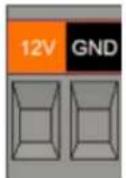
| Terminal Description | |
| 12V +12 | Input Power |
| GND Ground | |
NOTE: This is prewired at the factory to the internal 12 VDC power supply.
Controller Power, Power Fault and Fire Cutout Connector

| Terminal Description | |
| 12V +12 | Power for Controller |
| GND Ground for Controller | |
| PFT Power Fault, Output, Normally Open When Main Power is OK | |
| *FC Fire | Cutout Inputs, Normally Closed |
NOTE: 12V, GND and PFT is prewired at the factory to the controller and a jumper wire is connected between the FC inputs.
*FC is only included on models with lock power.
Output Power Connectors
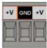
| Terminal Description | |
| +V +12 or +24 VDC Output, 375 mA MAX | |
| GND Ground | |
| +V +12 or +24 VDC Output, 375 mA MAX |
NOTE: This connector is only included on models with lock power.
On models that include power for door locks, the output voltage can be individually set for each of the four outputs. Jumpers are used to set the output voltage on the power module and LED's show the status of the output voltage. The images below shows the location of the of the jumpers and the LED's.
The GREEN LED indicates the output voltage is 12 VDC. The AMBER LED indicates the output voltage is 24 VDC. If the output is overloaded, the RED LED will be on.
NOTICE: The maximum output current for each of the four outputs is 375 mA @ 24V or 700 mA @ 12V.

Power Module Output LED Indicators (only on models with lock power)
On models that include power for door locks, use the output voltage selection jumpers as shown below to set the voltage to the desired value. Note: Make sure to check specifications of the door lock before applying power. Using the wrong voltage can damage the door lock or power module and void warranties.

Power Module Output Power Jumper Settings (only on models with lock power)
Power Connection
The power module is prewired, however the power outputs will have to field connected to the appropriate outputs. Before connecting the backup battery, connect the power cord to a grounded, unswitched 115 VAC outlet. The GREEN power indicator LED should be ON and the RED fire cutoff indicator LED should be off on the power board. The output voltage indicator LED's should be on according to the selector settings. Additionally the RED LED heartbeat indicator on the controller should be blinking approximately once per second.
After verifying all of the status LED's are in the expected conditions, connect the leads to the battery. First connect the negative wire (BLACK) then connect the positive wire (RED).
Calculating Estimated Standby Time
Standby time is determined by adding the maximum standby current draw of all the devices connected to the system to the current draw of the controller, and divide the amp hour rating of the standby battery by the total system load. Note: If the device rating is listed in mA it can be converted to amps by dividing by 1000. The table below shows and example of how to calculate estimated standby time.
| Example Standby Time Calculation | |||
| Device Standby Current | |||
| 4DMPL Controller 550 mA | 0.550 A | NOTE: Always include controller's standby current in the calculations. | |
| Reader 1 80 mA 0.080 A | |||
| Reader 2 100 mA 0.100 A | |||
| Door Lock 1 250 mA 0.250 A | |||
| Door Lock 2 250 mA 0.250 A | |||
| 1230 mA | 1.230 A Total System Load | ||
| Battery Rating 7.0 AH | |||
| Standby Time Calculation | 7.0 AH / 1.230 A | ~ 5.5 Hours Estimated Standby Time | |
NOTE: The actual standby time depends on the condition of the battery and the activity of the installed system.
Controller Features – 2 & 4 Door Systems
The following shows the controller's features and wiring components.
Controller Hardware Identification

4 Door Controller Layout (*only included on 4 Door models)
Controller Inputs
Controllers can monitor door position, request to exit and auxiliary (general purpose) inputs. All inputs are assigned default states that can be modified as needed through the user interface. The table below shows the default state for each of the inputs.
| Input Type Default State | |
| Door Position (status) Inputs Disabled | |
| Request to Exit Inputs Normally | Open, Momentary, Unsupervised |
| Auxiliary Inputs Normally Open, | Momentary, Unsupervised |
| Tamper Normally Open, Momentary, Unsupervised | |
| Power Fault Normally Open, Momentary, Unsupervised | |
Input Circuit Configurations
The table below shows the different input configurations. These types can be independently configured for each input by the user.
| Supervised Unsupervised | |
Normally Open Normally OpenNote: Use 1K Ohm Resistor |  |
Normally Closed Normally Closed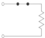 |  |
Controller Connectors
The controller is provided with plugin terminal blocks that are color coded and marked to indicate the proper connection for field wiring.
NOTE: The connector terminals are designed to accept 14-22 AWG solid or stranded wire.
The Minimum Cable Specifications for the wiring of inputs is 22 AWG Belden or equivalent with a maximum distance of 2000 feet (610 meters).
NOTE: All wiring shall conform with the National Electrical Code, NPFA70 and local building codes.
Input Wiring
All inputs may be configured for normally open or normally closed contacts. Door position, request to exit and auxiliary inputs may also be configured with for supervision to detect if wiring to the contact is broken or cut. Wires must not be routed in parallel with or in the same conduit with any high voltage AC wiring.
Request to Exit and Door Position Connectors

| Terminal Description | |
| REX Request to Exit Input, Normally Open, Normally Closed or Monitored | |
| GND Ground, Common Connection for REX and DC Inputs | |
| DC Door | Position Input, Normally Open, Normally Closed or Monitored. |
NOTE: REX and DC input types are user configurable options.
Request to Exit (REX) Inputs
A REX input activated the door output to unlock a door. A REX device can be a press to exit button, motion detector or other device mounted on the secured side of an entrance. REX features may be modified in Device Settings for Doors and can be set to normally open (NO), normally closed (NC) or monitored using either a series or parallel resistor. For applications where a manual unlocking device is used, such as a exit bar, REX activating the door output can be disabled.
Request to Exit Wiring
- Disconnect power from the controller.
- Determine if your REX device is normally open or normally closed (refer to the instructions provided by the REX manufacturer).
- Connect the REX device as shown.
- After power is applied to the controller, make sure to configure the controller in Device Settings for Doors and select the appropriate REX input type.
- After power is applied to the controller, verify the input is properly working.

Door Position Inputs
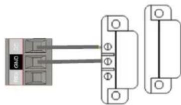
Monitors if the door is open or closed. The door switch (typically a magnetic reed switch, not provided) will change state when the door is opened or closed. To use this feature, it must be enabled in Device Settings for Doors. It can be set to normally open (NO), normally closed (NC) or monitored using either a series or parallel resistor.
Door Position Wiring
- Disconnect power from the controller.
- Determine if your door position switch is normally open or normally closed (refer to the instructions provided by the switch manufacturer).
- Connect the door position switch as shown.
-
After power is applied to the controller, make sure to configure the controller to use the door position switch in Device Settings for Doors and select the appropriate doo
-
After power is applied to the controller, verify the input is properly working.
natural_image
Pure electrical connector diagram without any text, numbers, or symbolsAuxiliary Inputs
Auxiliary inputs are used for general purposes and can be connected to devices such as alarms, detectors and devices that have a switched output. These inputs can be set to normally open (NO), normally closed (NC) or monitored using either a series or parallel resistor and these features may be modified in Device Settings for Aux Inputs.
Auxiliary inputs must be programmed to produce a defined action, such as activating an auxiliary output, using Event Actions.
Auxiliary Input Wiring
- Disconnect power from the controller.
-
Determine if device you are connecting to the Auxiliary input is normally open or normally closed (refer to the instructions provided by the device manufacturer).
-
Connect the device to the Auxiliary input as shown.
-
After power is applied to the controller, make sure to configure the controller in Device Settings for Doors and select the appropriate Auxiliary input type.
-
After power is applied to the controller, verify the input is properly working.

Power, Power Fault and Tamper Connector

| Terminal Description | |
| 12V +12 | VDC @ 5A (60W) Input Power |
| GND Ground for Input power | |
| PFT Power Fault Input, Normally Open or Normally Closed Contact | |
| GND Ground for Power Fault and Tamper Inputs | |
| TMP Tamper Switch Input, Normally Open or Normally Closed Contact | |
NOTE: A separate power supply recommended for the door locks.
Tamper
The tamper input may be used to monitor access to the access control system. This input can be set to normally open (NO) or normally closed (NC) in Device Settings for Controllers. Typically a tamper switch is mounted inside the enclosure containing the access control system in such a way that when the enclosure is opened, the switch is activated.
The access control system can be programmed using Event Actions to perform a system backup, activate an auxiliary output or send an email notification when a tamper input is detected. On models with integrated power, the tamper input is prewired to detect when the enclosure door is opened.
Tamper Input Wiring
- Disconnect power from the controller.
- Determine if device you are connecting to the Tamper input is normally open or normally closed (refer to the instructions provided by the device manufacturer).
- Connect the device to the Tamper input as shown.
- After power is applied to the controller, make sure to configure the controller in Device Settings for Controllers and select the appropriate Tamper input type.
- After power is applied to the controller, verify the input is properly working.

natural_image
Pure electrical connector diagram showing two connected modules with no text or symbolsPower Fault
The power input may be used to monitor the power supply connected to the access control system. This input can be set to normally open (NO) or normally closed (NC) in Device Settings for Controllers. Typically power supplies designed for access control will have a switched output that is activated when main power is lost and changed to battery backup.
The access control system can be programmed using Event Actions to perform a system backup, activate an auxiliary output or send an email notification when a power input is detected. On models with integrated power, the power fault is prewired to the Power Module and detects when main power is lost and the power module changes over to battery backup.
Power Fault Input Wiring
- Disconnect power from the controller.
- Determine if device you are connecting to the Power Fault input is normally open or normally closed (refer to the instructions provided by the device manufacturer).
- Connect the device to the Power Fault input as shown.
- After power is applied to the controller, make sure to configure the controller in Device Settings for Controllers and select the appropriate Power Fault input type.
- After power is applied to the controller, verify the input is properly working.

Power 12 VDC & GND
The Power Input requires a dedicated Class 2, 12 VDC power supply. On models with integrated power, the power is prewired to the controller. A RED LED on the controller flashes to indicate when 12 VDC is present.
NOTICE: A 12 VDC power supply must be used. Incorrect voltage will damage the product and void the warranty.
CABLE SPECIFICATIONS: Use a minimum size of UL listed 16 AWG, 2 conductor at a maximum distance of 4 feet (1.2 meters).
NOTE: Power supplies must be plugged into a dedicated receptacle that is not controlled by a switch.
Power Wiring
- Connect the power supply to the 12V and Ground terminals on the connector.
- Power should only be applied to the system when all connections are secured and tested, and when instructed to apply power.

In and Out Reader Connectors

| Terminal Description | |
| 12V +12 | VDC Power for the Readers |
| LED LED | Control for the In and Out Readers |
| BUZ Buzzer | Control for the In and Out Readers |
| ID0 In Reader, Data 0 | |
| ID1 In Reader, Data 1 | |
| OD0 Out | Reader, Data 0 |
| OD1 Out | Reader, Data 1 |
| GND Ground for the Readers | |
NOTE: Reader current is limited by an auto resetting fuse on the controller. Improper connection may damage the controller and void the warranty.
Readers
The controller can be connected to Wiegand type readers or keypads. Each door on the controller supports a primary (entrance) In Reader and a secondary (exit) Out Reader.
The maximum power available through the controller for an individual reader is 300mA @ 12VDC with a combined maxim for the controller of 1500mA. Exceeding the maximum power for an individual reader or for the controller may damage the controller, void the warranty and will cause erratic operation. Refer to the manufacturer's documentation to determine the reader's power requirements. Wires must not be routed in parallel with or in the same conduit with any high voltage AC wiring.
The Minimum Cable Specifications for readers is a Belden shielded, twisted, 6 conductor plus ground cable; 22 AWG when the reader is mounted up to 250 feet from the controller and 18 AWG when the reader is mounted up to 500 feet from the controller.
Note: Use UL294 listed readers for all installations such as HID ProxPoint Plus or similar. All wiring shall conform with the National Electrical Code, NPFA70 and local building codes.
Reader Wiring
-
Disconnect power from the controller.
-
Connect the color coded wires from the reader to the appropriate terminals on the reader connector as shown. Refer to manufacturer's instructions for exact color codes for each connection.
-
Remove excess shield from the reader cable to prevent interference with the controller's electronics or other electrical circuits. Tape off any exposed shield with electrical tape.
-
Reader shields must be grounded per the manufacture's requirements.
-
Make sure to properly ground the reader shield.
-
After power is applied to the controller, verify the reader is properly working.
| In & Out Reader Wiring | ||||
| Reader Connector | Color Description | Typical IN Reader Wire Color | Typical Out Reader Wire Color | |
| 8 | Ground B | |||
| 7 White | Out Reader, D1 X White | |||
| 6 Green | Out Reader, D0 X Green | |||
| 5 White | In Reader, D1 | White X | ||
| 4 | Green | In Reader, D0 | Green | X |
| 3 | Orange | Buzzer Control | Blue | Blue |
| 2 | Blue | LED Control | Brown | Brown |
| 1 | Red | 12 VDC | Red | Red |

Controller Outputs
The controller has door output and auxiliary output relays that may be activated in response to reader activity, time schedules or event actions. The outputs are assigned default features that can be configured in Device Settings for Doors or Auxiliary Outputs. The table below shows the default state for each type of output.
| Output | Default State | Default Response |
| Door Output | Not Energized, Single Pulse | 3 second activation time in response to valid access credentials |
| Auxiliary Output | Not Energized, Single Pulse | None. Must be configured in Device Settings or Event Actions |
Output Wiring Requirements
The wire used must be of the proper gauge for the load current and distance from the controller to the load. Wires must not be routed in parallel with or in the same conduit with any high voltage AC wiring and all wiring shall conform with the National Electrical Code, NPFA70 and local building codes. The table below shows recommendations for wire gauge based on load and distance from the controller.
| Total Load (Amps) | Voltage (AC or DC) | Wire Gauge and Distance (feet) | ||||
| 14 16 | 18 20 | 22 | ||||
| 0.5 A | 12V 1500 | 1000 600 | 375 225 | |||
| 24V 2000 | 1200 750 | 450 300 | ||||
| 1.0 A | 12V 800 | 500 300 | 200 100 | |||
| 24V 1000 | 600 400 | 200 150 | ||||
| 2.0A | 12V 400 | 240 150 | 90 60 | |||
| 24V 480 | 300 180 | 120 70 | ||||
Door and Auxiliary Output Connectors

| Terminal | Description |
| NC | Normally Closed Dry Relay Contact |
| C | Common Relay Contact |
| NO | Normally Open Dry Relay Contact |
NOTE: The maxim capacity of the Door and Auxiliary output relays is 24 VDC @ 2 Amps. Always use a dedicated power supply for Door and Auxiliary Outputs.
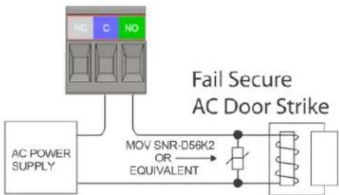
Door Lock Wiring
Door outputs can be configured to operate in a fail safe or fail secure mode. Connect the door locking device to the door output connector as shown below. Refer to the manufacturer's specifications to determine the correct operating voltage, current and configuration. Use a power supply dedicated for door lock use. On models that include power for the door locks, the built in power supply may be used to power 12V or 24V DC door locking devices.
Fail Secure DC Door Strike
Without power, the door strike is locked.
Fail Safe DC Door Strike
Without power, the door strike is unlocked.
Fail Secure AC Door Strike
Without power, the door strike is locked.

flowchart
graph TD
    A["DC POWER SUPPLY"] --> B["Diode 1N4933 OR EQUIVALENT"]
    B --> C["Fail Secure DC Door Strike"]
    C --> D["+"]
    C --> E["-"]

flowchart
graph TD
    A["AC POWER SUPPLY"] --> B["NO C NO"]
    B --> C["MOV SNR-D56K2 OR EQUIVALENT"]
    C --> D["Motor Coil"]
    D --> E["AC Gate"]
    style A fill:#f9f,stroke:#333
    style B fill:#ccf,stroke:#333
    style C fill:#cfc,stroke:#333
    style D fill:#fcc,stroke:#333
    style E fill:#ffc,stroke:#333
Adding 2 Door Expansion
Controllers with only 2 doors can be expanded to 4 doors by adding an optional 2 door expansion module. The module plugs into the back of the 2 door controller and provides the additional inputs and outputs. The 2 Door Expansion Module in installed as follows.
- Login to the controller and manually backup user data and log data.
- Disconnect the backup battery from the power module.
- Disconnect main power from the system by removing the power cord.
- The expansion module mounts under the 2 door controller and the 2 door controller will have to temporary removed. Note the location of all the plugin connectors and carefully unplug them and unplug the network cable.
- Remove the 4 screws securing the controller to the mounting posts and carefully remove the 2 door controller. The screws will be used to reinstall the controller.
- Remove the longer standoffs. These will be used to reinstall the controller.
- Align the 2 door expansion over the short standoffs attached to the enclosure, with the reader connectors towards the top of the enclosure. Use the longer standoffs, removed in step 6, to secure the expansion module to the short standoffs. Do not over tighten or the expansion module could be damaged.
- Plug the ribbon cable from the expansion module into the 26 pin connector on the back of the 2 door controller. Make sure the connector is properly positioned and aligned. An improper connection will damage the expansion module and the controller.
- Align the 2 door controller over the longer standoffs and use the screws removed in step 5 to secure the controller. Do not over tighten or the controller could be damaged.
- Reconnect the plugin connectors and the network cable and make the connections to the expansion module before reapplying power or connecting the backup battery.

Powering On and Connecting to a Network
Controllers must be located in a secure area and connected to a network that is protected by a security system (firewall, etc.). Before connecting the controller to the network, obtain the following information from you network administrator. Note: a Static IP address should be used when a controller is configured as a server controller. Client controllers may use DHCP.
√IP address
√Subnet Mask
√Gateway
√DNS 1 and DNS 2
Preparing for the Network
In most cases, the controllers IP address will have to be changed to allow the controller to be recognized by the local network. The controller's IP address is changed as follows.
- Connect a programming computer directly to the Ethernet port of the controller. A standard CAT-5 cable is used for direct connection. A crossover cable is not required.
- Assign a static IP address to the computer of 192.168.0.10. For instructions on how to change the static IP address of a Windows computer visit: https://support.microsoft.com/en-us/help/15089/windows-change-tcp-ip-settings
- The factory default IP address of the controller is 192.168.0.250. Open a web browser, such as Google Chrome, and enter the default IP address into the address bar.
TIP: As an alternative to directly connecting a cable, the provided IP Installer utility can be used to change the controller's IP address. See the section below on how to use the utility.
-
The controller's login page is displayed as shown. To login enter the default User ID: admin and default PW: admin
-
Controllers can be licensed as a server or a client. After first time login, the license page is displayed. To get a license key, first click on the Edit button. On the next page, click on A, the Get License Key for a SERVER or click on B, the Get Client Key for a CLIENT. Click OK to confirm and the license key will be auto populated. Finish by clicking C, Apply License Key and the controller will restart.

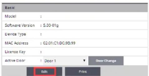
NOTE: The controller needs to access the Internet to obtain a license key.

- When the controller is licensed for a server, after logging in, the system configuration Wizard is started. The Wizard is a guide that can be used to collect the basic information required to set up a system. The network settings can be configured in the Wizard or by browsing to the Network Configuration page as shown.

Wizard Starting Page
- The network configurations may be accessed through the Sitemap by first clicking the icon at the bottom of the page, then clicking IP Address under Network Settings.

Accessing the Site Map
- After entering the network information, click Save & Reboot and the controller will reboot. Typically rebooting will take less than 2 minutes.

Network Settings Page
- After disconnecting the programming computer, the controller is ready for the local network.
NOTE: System data may be lost if the controller is powered down without performing Save & Reboot.
Connecting to the Local Network
Plug the Ethernet cable into the port on the controller and connect to the local area network as shown below. If the network connection is functioning properly the LAN LED's on the controller will blink. Computers connected to the local network will be able to access the system using the IP address of the controller.
The Minimum Cable Specifications network connection is CAT 5 or better with an RJ-45 connector, wired straight through to a network switch or router.
Note: For UL installations, the maximum Ethernet cable length
is 98.5 feet (30 meters).
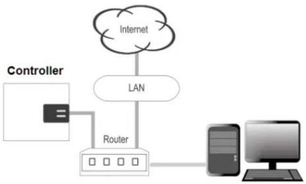
flowchart
graph TD
    A["Controller"] --> B["Router"]
    B --> C["Internet"]
    C --> D["LAN"]
    D --> E["Mobile Device"]
    E --> F["Computer"]
NOTE: LAN connection is only required for monitoring, reporting and configuration. Once the system is configured, it will operate without a LAN connection.
Adding Clients to Systems
Some systems have the ability to add additional controllers to increase the number of doors, inputs or outputs or control elevators. Clients are configured through the system's server, but must first be linked to the server.
Setting the Client's Network
- Connect a programming PC directly to the controller as described in the section Preparing for the Network.
- Login using the default ID: admin and default PW: admin
- After login, the client's network page is displayed. Click Edit.
- Change the IP address of the client controller. It is recommended to set this to DHCP.
- Enter the IP address of the server controller and the server's port number (the default port number is 20000).
- Enter the password and click Save.
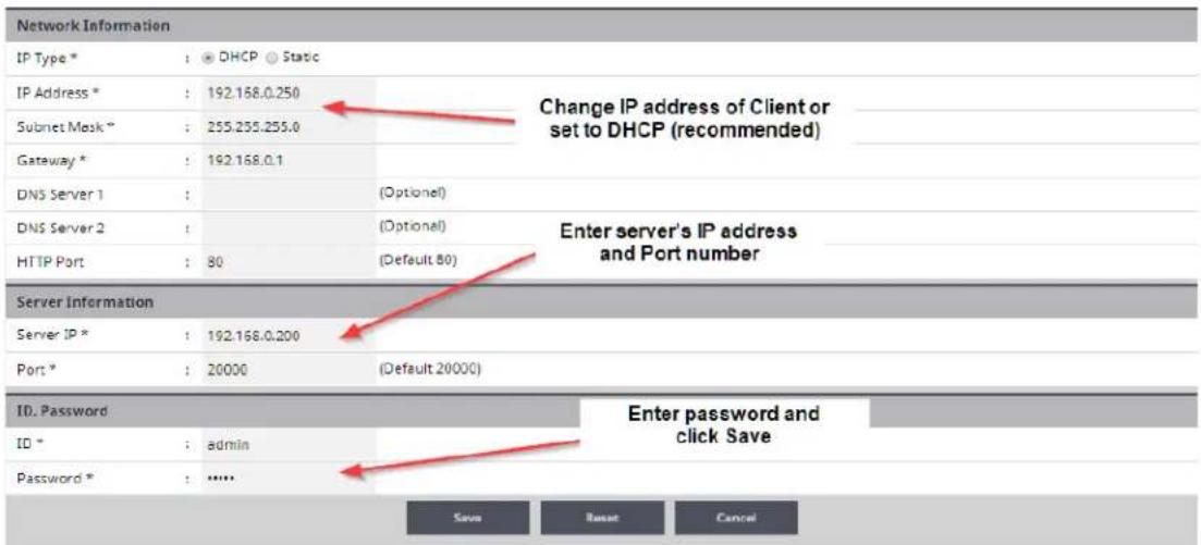
Linking the Client to the Server
- Login to the system's server.
- After logging in, browse to the Site Management and select Client Management.
- The client will appear in the client management list. Click on the button to connect the client to the server.
![No Name Type IP Address MAC Address Alive Version Model No 1 Client 1 Door 1 192.168.0.55 02:01:C1:DC:98:99 On 5.00-01d NEPTUNE-H501 [1] Click to conncet Client to Server](/content/2026/05/972775/images/a690a581c3ceac5939fa3f2a3c49e1a995a911e6d4d7b8a0b5aa0197d9310664.jpg)
Client Management
IP Installer
IP Installer is a Microsoft Windows® PC utility that is on the USB thumb drive shipped with all systems. This utility can be used to locate a controller on the local area network. It also provides a method of changing the IP address of a server or client controller and is an alternative to directly connecting clients. To use IP Installer, follow the steps below.
-
Locate IP Installer on the USB thumb drive and install it on a Windows PC that is connected to the local network that will be used by the server and client controllers.
-
Connect all of the controllers to local network.
-
Run IP Installer. If you PC has multiple network adapters, select the adapter in the Network Card list box that is connected to the local network used by the controller, and click Scan to locate the controllers. When controllers are located, they will be listed in IP Installer.
-
In this example, a server controller is located at 192.168.0.200 and client controller is located at 192.168.0.250. The client's IP address can be changed and the client can be assigned to a server by first clicking on the client in the list, then click the Set Network button.
-
In the IP Setting popup, change the client's IP to static IP address or to a DHCP. Note that servers must be set to static IP address.
-
In the IP Setting popup, change the client's Server Info. In this example, the Server IP is 192.168.0.200 and the Server Port is 20000.
-
Enter the IP Installer password 1234 and click OK. This will update the client's IP address settings and assign it to a server. When the network changes are complete, the client will appear in the list with the new settings.


System Configuration and Programming
The controller is programmed and managed using a web browser on any computer connected to the local area network. The controller's basic settings can be programmed using the Wizard tool. The Wizard tool helps ensure that the required settings are configured for normal operation.
For specific programming instructions, refer to the Users Programming Guide, Part Number 100104-SP.
Trouble Shooting
| Question Solution | |
| The controller does not power up. | - Check the AC outlet's voltage used to power the controller.- For systems using a Fire Cutout, check the status of the fire cutout input to see the power has been deactivated.- Check wiring from the power supply to the controller.- For systems using a Power Module, check for +12 VDC at the Power Input Connector. If +12 VDC is not present, the internal power supply may be damaged and need to be replaced.- Check for +12 VDC at the Power Connector for the Controller. If +12VDC is present and the RED LED's on the Controller are off, the input fuse may be blown. This fuse is not field replaceable.- If the measured voltage is less than 11 VDC, the system may be overloaded.Disconnect all readers, door and AUX outputs and check if the controller powers up. |
| The controller power up but does not respond to card reader inputs. | - Check that the card and the card reader are compatible.- Measure the power at the reader connection. If no voltage is present, the reader fuse may be blown or overloaded. Disconnect the reader wiring and check for proper voltage.- Check the wiring to the reader. Disconnect the field wires to the reader and directly wire a reader to the controller. If the reader works, the field wiring may be faulty. |
| No network communications with Controller. | - If the Ethernet LAN LED's are off or solid, then there is no physical connection to the network. Check network cabling at the Controller and at the router or switch.- Verify the correct IP, Gateway, Subnet and DNS address are being used for the network.- Have the network administrator verify that firewall rules or port restrictions are not blocking network access to the Controller.- Directly connect a programming PC to the Controller as described in the installation instructions to check Ethernet communications. Note that you may need to reset the IP address of the controller. |
| How to reboot the controller? | - For a hardware reboot, momentary press the controller's Reboot push button.- It will take approximately 1 minute for the controller to reboot and the UI can be accessed. |
| How to reset the IP address of the controller to factory default? | - Press and Hold the IP Default push button on the controller for 20 seconds.- The Controller will reboot and set the IP address to 192.168.0.250.- It will take approximately 1 minute for the controller to reboot and the UI can be accessed.- The Controller's IP address can be changed from the UI. |
| How to restore factory defaults to a controller? | Note:If the controller is factory defaulted, all configuration and user information will be lost, including the license key.- Press and Hold the Factory Default push button on the controller for 20 seconds.- The Controller will reboot and the factory with the factory defaults, including the default IP address.- It will take approximately 1 minute for the controller to reboot and the UI can be accessed.- After installing the license key the controller can be reconfigured from the UI. |
Trouble Shooting
| Question Solution | |
| How to obtain a license key for an unlicensed controller? | – The controller's MAC address is required to obtain a license key. This is printed on the controller or can be found on the license page after logging in to the UI.– Visit the License On Demand web server to obtain the license key. |
| Can not obtain a license key after first login. | The controller needs access to the Internet to retrieve a license key. If an Internet connection is not available, the license key can be retrieved directly from the License On Demand web server. |
Testing, Maintenance and Service
A monthly test of the system and all the components is recommended.
√Check that all used inputs and outputs are correctly working with the connected devices.
√Check that the system and log backups are occurring at the scheduled times.
√ Check for proper operation of the battery backup. NOTE: Backup system data before performing a battery test.
The system requires little maintenance, however it is recommend to check the following every 6 months.
√Doors on system enclosures are secure.
√Enclosures are clean and dry.
√All wires are securely connected to the terminals and proper strain relief is used.
√Proper bushings or fitting are installed in knock out for wires and wires are not cut or chaffed.
√Check date code on backup battery and replace if needed.
These systems contain Class 2 circuits. There are no serviceable parts on the controllers. Do not alter or tamper with any of the components of the system. Doing so will void the warranties and violate FCC rules.
Parts List
| Order Model Description | |
| ADMTAMP Tamper | Switch |
| ASWAP2D 2 Door | Controller Replacement |
| A2M 2 Door Expansion Module (converts 2 door controller into 4 door controller) | |
| SPB1224 Power Module with Door Lock Power | |
| APSB12 Power Module without Door Lock Power | |
| ASWITCHPS75 75 W Power Supply | |
| Please contact customer service to order replacement parts. | |
Contact & Warranty Information
Corporate Office
Speco Technologies
200 New Highway
Amityville, NY 11701
Phone: 800.645.5516
FAX: 631.957.9142
www.specotech.com
For Technical Assistance
Phone: 800.645.5516 option 3
email: techsupport@specotech.com
Refer to our website for warranty information.
Document Number: 100100-SP REV B


- Speco Access Control System Installation Instructions
- Table of Contents
- Notifications
- Copyright
- Approvals
- Notice
- Introduction
- Access Control Overview
- System Overview
- Installation of 2 & 4 Door Systems
- Installation Check List
- Locating the Controller for Installation
- Mounting the Metal Enclosure – 2 & 4 Door Systems
- Tamper Detection
- System Power
- Power Fault Detection
- Door Lock Power
- Fire Release Input
- Battery Connection
- Battery Warnings
- Output Power Connectors
- Power Connection
- Calculating Estimated Standby Time
- Controller Features – 2 & 4 Door Systems
- Controller Hardware Identification
- Controller Inputs
- Input Circuit Configurations
- Controller Connectors
- Input Wiring
- Request to Exit and Door Position Connectors
- Request to Exit (REX) Inputs
- Request to Exit Wiring
- Door Position Inputs
- Door Position Wiring
- Auxiliary Inputs
- Auxiliary Input Wiring
- Power, Power Fault and Tamper Connector
- Tamper
- Tamper Input Wiring
- Power Fault
- Power Fault Input Wiring
- Power 12 VDC & GND
- Power Wiring
- In and Out Reader Connectors
- Readers
- Reader Wiring
- Controller Outputs
- Output Wiring Requirements
- Door and Auxiliary Output Connectors
- Door Lock Wiring
- Fail Secure DC Door Strike
- Fail Safe DC Door Strike
- Fail Secure AC Door Strike
- Adding 2 Door Expansion
- Powering On and Connecting to a Network
- Preparing for the Network
- Connecting to the Local Network
- Adding Clients to Systems
- Setting the Client's Network
- Linking the Client to the Server
- IP Installer
- System Configuration and Programming
- Testing, Maintenance and Service
- Contact & Warranty Information
- Corporate Office
Brand : Speco Technologies
Model : A2E4P
Category : Access Control System