
Portico II - Processor Rupert Neve Designs - Free user manual and instructions
Find the device manual for free Portico II Rupert Neve Designs in PDF.


| Product Type | Channel Strip / Processor |
| Brand | Rupert Neve Designs |
| Model | Portico II |
| Rackmount Size | 2U 19-inch rackmount |
| Dimensions (W x H x D) | 19" x 3.5" x 10" (483 mm x 89 mm x 254 mm) |
| Weight | 15 lbs (6.8 kg) |
| Power Supply | Internal, 100-240V AC, 50/60 Hz, 30W |
| Inputs | XLR (mic/line), 1/4" TRS (line/instrument) |
| Outputs | XLR (balanced line), 1/4" TRS (unbalanced) |
| Frequency Response | 20 Hz - 20 kHz ±0.5 dB |
| Total Harmonic Distortion | < 0.01% @ 1 kHz, +20 dBu output |
| Signal-to-Noise Ratio | > 110 dB (A-weighted) |
| Mic Preamp Gain | 0 dB to +66 dB |
| Compressor | Variable ratio (1.5:1 to 60:1), threshold, attack, release, makeup gain |
| Equalizer | 3-band semi-parametric with shelving and peaking filters |
| Transformer | Custom Rupert Neve designs input and output transformers |
| Cooling | Passive convection, no fan |
| Maintenance | Occasional cleaning of exterior with dry cloth; no user-serviceable parts inside |
| Safety | Do not expose to moisture; disconnect power before cleaning; ensure proper ventilation |
| Spare Parts / Repairability | Contact authorized service center; some components (e.g., transformers) available as spare parts |
| General Information | Designed for professional studio and live sound applications; provides vintage-style analog warmth with modern clarity |
Frequently Asked Questions - Portico II Rupert Neve Designs
User questions about Portico II Rupert Neve Designs
0 question about this device. Answer the ones you know or ask your own.
Ask a new question about this device
Download the instructions for your Processor in PDF format for free! Find your manual Portico II - Rupert Neve Designs and take your electronic device back in hand. On this page are published all the documents necessary for the use of your device. Portico II by Rupert Neve Designs.
USER MANUAL Portico II Rupert Neve Designs
Thank you for your purchase of a Portico II Channel module.
Everyone at Rupert Neve Designs hope you enjoy using this tool as much as we have enjoyed designing and building it. The name “Portico II” will be used for a series of new ultra-high end professional products that will share some traits. Please take note of the following list of safety concerns and power requirements before the use of this or any Portico II Series product.
Safety
It's usual to provide a list of "do's and don'ts" under this heading but mostly these amount to common sense issues. However, here are important safety requirements that must be adhered to:
Heat generated by the Channel module is radiated through the case work and by convection through the ventilation holes, therefore the holes should not be covered or blocked. To avoid overheating, Portico II units should not be stacked immediately above or adjacent to other equipment that gets hot, and one rack space above the unit should be left open for heat ventilation.
Also bear in mind that other equipment may radiate strong hum fields which could spoil the performance of your Portico II module.
Protect the power cord from being walked on or pinched, particularly at plugs convenience receptacles and the point where they exit from the apparatus. Do not defeat the safety purpose of the polarized or grounding-type plug. A polarized plug has two blades with one wider than the other. A grounding type plug has two blades and a third grounding prong. The wide blade or the third prong are provided for your safety. Unplug the module during lightning storms or when unused for long periods of time.
Don't operate your Portico II module in or around water! Electronic equipment and liquids are not good friends. If any liquid is spilled, such as soda, coffee, alcoholic or other drink, the sugars and acids will have a very detrimental effect. Sugar crystals act like little rectifiers and can produce noise (crackles, etc.). SWITCH OFF IMMEDIATELY because once current starts to flow the mixture hardens, can get very hot (burnt toffee!) and cause permanent and costly damage. If it gets wet and you suspect that good clean water may have gotten in, immediately unplug the unit, and remove it from the source of water. Please contact support as soon as possible at support@rupertneve.com for resolution. Clean only with dry cloth.
Don't be tempted to operate a Portico II unit with the cover removed. The cover provides magnetic screening from hum and R.F. stray fields.
Power Requirements
Each Portico II unit has a high quality, low noise switching power supply that is further filtered and shunt regulated for an exceptionally quiet and reliable power source for the audio circuits. The power supply is considered “universal” in the sense that it will accept 100V through 240V AC and complies with standard mains voltages around the world. Be absolutely sure to disconnect mains power (remove the power cable from the IEC power connector at the back panel) before checking the fuse. The fuse is located in the IEC power input connector and is accessed by opening the small panel labeled “FUSE”. The fuse should always be replaced with the correct value and type. The Portico II power supply requires a 5x20 mm 2.5 amp fast acting ceramic body fuse Bussman type GDA 2.5A or equivalent.
The fuse is a protection device intended to prevent additional damage or hazard if the Portico II unit develops a problem. However sometimes a fuse may "pop" due to a mains surge and need to be replaced (it probably did protect the Portico II). The symptom of a blown fuse is simply that the unit does not power up. Disconnect the power cable, try replacing the fuse, re-insert the power cable, push the "Power" button. If this does not solve the problem or the fuse "pops" again there may be a problem with the Portico II you should contact your dealer or email support@rupertneve.com or phone 512-847-3013.
Portico II Channel: Block Diagram
PORTICO II

flowchart
graph LR
    A["Line"] --> B["THRU"]
    B --> C["Di"]
    C --> D["Thru"]
    D --> E["Mic"]
    E --> F["DI Detect (Auto)"]
    F --> G["Gain 0-66dB"]
    G --> H["Line"]
    H --> I["Phase Reverse"]
    I --> J["Trim +/-6dB"]
    J --> K["From Sidechain"]
    K --> L["HPF In"]
    L --> M["S/C HPF"]
    M --> N["To Sidechain"]
    N --> O["EQ Pre / Post"]
    O --> P["Output"]
    P --> Q["METER"]
    Q --> R["Mute"]
    R --> S["Output"]

    T["All EQ In"] --> U["LF In"]
    U --> V["LMF / HMF In"]
    V --> W["HF In"]
    W --> X["De-ess"]

    Y["Comp In"] --> Z["Sidechain"]
    Z --> AA["Link"]
    AA --> AB["GR METER"]

    AC["EQ Compressor"] --> AD["Output"]
    AE["Texture"] --> AF["Meter"]
    AF --> AG["Output"]

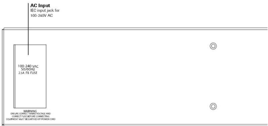
Portico II Channel: Front / Back Panel


The Rupert Neve Designs Portico II™ Channel
The Rupert Neve Designs Portico II Channel is a full 19" rack width, 3.5" (2U) with standard rack mounting "ears". As with the entire Portico II range, the construction incorporates a heavy and robust steel shell that provides total magnetic screening and exceptional mechanical stability. The front panel is machined from a solid .20 inch aluminum plate with a steel sub panel behind it.
The name says a lot about the device but certainly not everything. The audio electronics use higher power supply voltage compared to most audio gear and in this case use +36 and -36 volt power supply rails. The signal path has manysimilar circuits as the Rupert Neve Designs flagship console, the 5088. Amplification is handled with discrete (individual transistors) operational amplifiers (gain blocks). These discrete circuits are in the tradition of Rupert's original circuits used in recording consoles from the 70's and in many ways sound similar, however there are refinements in noise, slew rate, dynamic range and particularly avoidance of unpleasant high frequency distortion artifacts. Also following Rupert's traditional approaches, these gain stages are married to custom designed input and output transformers. Not only is the output transformer custom designed for the Portico II, it is the largest toroid output transformer that he has used for a line level device.
Some wonder whether it is better to use a separate boutique mic pre-amp, EQ' and compressor versus a typical channel strip processor. In most cases, the separates have the advantage of "it is your choice", however one would hope to have a variety of choices to choose from and have made the best choices. Another likely advantage for the separates is that most channel strips have at least one weak link, one stage or processor that is virtually useless. However, most channel modules are relatively convenient and easier to use and to patch.
The Portico II is a unique channel module in that each of the 3 main sections, the mic pre, the EQ and the compressor are based on 3 separate products that each have the Rupert Neve heritage, a huge fan base and stacks of great reviews. We also however have added refinements and features to those circuits like the SILK+ and TEXTURE knob, the De-Esser, the Blend and the FAST mode features that our friends and customers suggested be added to the originals. Unnecessary circuitry (a few input and output stages) could be removed while truly useful and convenient internal patching features could be added with a few switches rather than with patch-bays and patch cables. While combining three modules into the Portico II, we were able to add a few more features in the internal routing like the HPF to Side-Chain, and the EQ / Compressor order selection. In this case, the sum is obviously greater than the individual parts - you get 3 very powerful and versatile boutique processors that have evolved into this synergistic channel module.
MICROPHONE INPUT
The microphone input is balanced but not floating, being a variant of an instrumentation amplifier. Our well-proven “Transformer-Like-Amplifier” (T.L.A.) configuration is used, which includes an accurate toroidal Common Mode Low Pass Filter that rejects Common Mode signals and excludes frequencies above 150 kHz. (There are high powered broadcast transmitters at and above this frequency in several Continents and, even if you can’t hear them, any vestigial intermodulation products must be excluded!)
When the Mic Gain switch and Trim controls are set to Unity (0 dB) the Portico II microphone pre-amplifier can handle a balanced input signal of more than +20 dBu without an input attenuator pad! This is a unique feature that enables this input to double as an additional line input.
THE LINE INPUT
The Line Input is a balanced female XLR jack (Pin 2 hot). As previously mentioned, the MICROPHONE XLR inputs can double as line inputs due to the unusual headroom they exhibit, but we also included dedicated line inputs with separate jacks and a position on the input gain to select them. Electronically, there is very little difference except between the Mic and Line inputs except that the Mic inputs have much more gain available and the Line inputs have one less gain stage if minimalism is a concern or phantom power might be dangerous.
THE LINE OUTPUT
The output stage is also similar to that of the 5088 console, using high voltage class-A discrete circuitry, driving a carefully configured output transformer that can deliver a full +25dBu from the balanced and ground-free secondary winding.
This maximum output level provides a large margin over and above the likely maximum requirement of any destination equipment to which the channel module may be connected. This is especially true when feeding digital equipment!
Freedom from the interference fields that are inevitably present in any control room is virtually guaranteed by the balanced, ground-free design used in the Channel Strip. The classic Rupert Neve designed modules always used transformers, as do a number of other high quality vintage modules still in current use.
High quality transformer connectivity has been used for many years, enabling modular amplifier units to deliver the sonic performance for which they are famous. The outputs are very appropriate for driving unusually long lines that may be needed when used remotely.
Bear in mind that human ears are very sensitive and can perceive incredibly minute interference signals that are not part of the “desired” signal. If unbalanced connections are used, great care must be exercised to avoid ground loops and common signal paths. Reduced immunity from various forms of interference can be tolerated (sometimes) but usually results in a loss of that transparent musical resolution that we all love.
However, the output of any Portico II transformer-coupled XLR may be used with one side grounded if necessary, for example to use with “Hi-Fi”, “consumer” or other unbalanced audio gear, without degrading the performance of such devices. Care must be exercised when using ancillary equipment to avoid overloading it.
THE SIDE CHAIN INSERT JACKS
This pair of jacks are only used to perform some fine tuning of the compressor operation. The audio that normally controls the compressor is available on the “SIDECHAIN OUTPUT” jack. One can take this audio and pass it through an external equalizer then return it back to the “SIDECHAIN INPUT” jack. Now changes on the external EQ affect the sensitivity of the compressor. For example, if you cut some low frequencies on the external EQ, then the compressor will tend to not want to reduce the gain as much on bass notes. This is not the same thing as simply boosting lows on the Portico II Equalizer because the latter changes the frequency response while the former changes levels. Similarly, one could boost highs (6kHz for example) on the external EQ and cause the compressor to be extra-sensitive to that part of the spectrum which happens to correspond with sibilance (esses). This can act as one type
of a de-esser that pulls down the volume of the whole signal if it senses an “ess”. And it should be noted that the built-in Channel Strip De-Esser acts in a different way and only reduces the narrow area of frequencies that the High Mid EQ is set for. You would be correct if you thought that both of these types of de-essing can be used independently for a “difficult” track.
A few notes about these jacks. They are unbalanced and ideally best suited to be used with unbalanced equipment. However most balanced EQ's will work fine interfaced to these jacks. The simple symptom of a balanced / unbalanced mismatch is that the “compression meter” will indicate a significant change of compression depth (like zero) when the EQ is set flat. Keep in mind that nobody hears this signal path so that any old nasty sounding EQ you tossed in a closet years ago might be perfectly suited for a side chain insert task.
THE LINK CONNECTORS
These jacks are used when one is lucky enough to have two (or more) Portico Channels and would like to use them with a stereo source and specifically when one wants to have the two compressors follow and match each other. This helps to preserve the stereo image because both the compressor for the left and the compressor for the right will then raise and lower gain the same amount.
MICROPHONE PREAMPLIFIER DESIGN NOTES
In former years, before the introduction of solid state amplifiers, transformers were necessary to step up to the very high input impedance of tubes, and to provide a balanced input for the microphone line. An input impedance of 1,000 or 1,200 ohms became established for microphones having a source impedance of 150 or 200 ohms, with connection being made on a twisted twin screened cable (This type of cable, while excellent for low impedance work, has high capacitance between its conductors and between each conductor and screen. Resultant high frequency losses are excessive with piezo pickups and may cause resonances with magnetic pickups.) Thus microphones were not heavily loaded. Condenser microphones worked off high voltage supplies (300V!) on the studio floor which polarized the diaphragms and powered a built-in pre-amplifier. More and more microphones were needed as “Pop” music gained ground and this led to the popular and efficient method of 48-volt “Phantom” powering that was built into the multi-channel recording Console – in place of numerous bulky supplies littering the studio, a miniature pre-amplifier now being fitted inside the microphone casing.
The 48-volt supply was fed to the microphone through balancing resistors so it was impossible for this voltage to actually reach the microphone, resulting in low polarizing volts and virtual starvation of the little pre-amp inside the microphone. Nevertheless amazingly good microphones were designed and made, becoming the familiar product we use today. If a low value resistive load is connected to the output of an amplifier, that amplifier has to produce power in order to maintain a voltage across that load. Obviously if we want more voltage (output from the microphone) we need to provide a larger supply for the amplifier or settle for a lighter load. A microphone is a voltage generator, not a power amplifier. Most microphones give their most accurate performance when they are not loaded by the input impedance of a traditional preamplifier. If the microphone uses an electronic circuit (transformerless) output, a low value of load impedance can possibly stress the little microphone pre-amplifier, causing slew rate and compression at high levels.
On the other hand, a high value of load impedance allows the microphone to “breathe” and give of its best, this being particularly advantageous with very high level percussive sounds. If the microphone has an inductive source (such as would be the case if it has a transformer output) a low value of load
impedance causes the high frequencies to roll off due to leakage inductance in the transformer in addition to the above amplifier distortion (This can be an advantage with some microphones!).
For this reason we have provided a high value of input impedance that will load microphones to the smallest possible extent and makes the best possible use of that limited “Phantom” 48-volts supply.
A NOTE ON DISTORTION
The human hearing system is a remarkably complex mechanism and we seem to be learning more details about its workings all the time. For example, Oohashi demonstrated that arbitrarily filtering out ultrasonic information that is generally considered above our hearing range had a measurable effect on listener's electroencephalo-grams. Kunchur describes several demonstrations that have shown that our hearing is capable of approximately twice the timing resolution than a limit of 20 kHz might imply (F=1/T or T=1/F). His peer reviewed papers demonstrated that we can hear timing resolution at approximately with 5 microsecond resolution (20 kHz implies a 9 microsecond temporal resolution, while a CD at 44.1k sample rate has a best-case temporal resolution of 23 microseconds).
It is also well understood that we can perceive steady tones even when buried under 20 to 30 dB of noise. And we know that most gain stages exhibit rising distortion at higher frequencies, including more IM distortion. One common IM test is to mix 19 kHz and 20 kHz sine waves, send them through a device and then measure how much 1 kHz is generated (20-19=1). All this hints at the importance of maintaining a sufficient bandwidth with minimal phase shift, while at the same time minimizing high frequency artifacts and distortions. All of the above and our experience listening and designing suggest that there are many subtle aspects to hearing that are beyond the realm of simple traditional measurement characterizations.
The way in which an analog amplifier handles very small signals is as important as the way it behaves at high levels. For low distortion, an analog amplifier must have a linear transfer characteristic, in other words, the output signal must be an exact replica of the input signal, differing only in magnitude. The magnitude can be controlled by a gain control or fader (consisting of a high quality variable resistor that, by definition, has a linear transfer characteristic.) A dynamics controller - i.e. a compressor, limiter or expander - is a gain control that can adjust gain of the amplifier very rapidly in response to the fluctuating audio signal, ideally without introducing significant distortion, i.e. it must have a linear transfer characteristic. But, by definition, rapidly changing gain means that a signal “starting out” to be linear and, therefore without distortion, gets changed on the way to produce a different amplitude.
Inevitably our data bank of “natural” sound is built up on the basis of our personal experience and this must surely emphasize the importance of listening to “natural” sound, and high quality musical instruments within acoustic environments that is subjectively pleasing so as to develop keen awareness that will contribute to a reliable data bank. Humans who have not experienced enough “natural” sound may well have a flawed data bank! Quality recording equipment should be capable of retaining “natural” sound and this is indeed the traditional measuring stick. And “creative” musical equipment should provide the tools to manipulate the sound to enhance the emotional appeal of the music without destroying it. Memory and knowledge of real acoustic and musical events may be the biggest tool and advantage any recording engineer may possess.
One needs to be very careful when one hears traces of distortion prior to recording because some flavors of distortion that might seem acceptable (or even stylish) initially, may later prove to cause irreparable damage to parts of the sound (for example, “warm lows” but “harsh sibilance”) or in louder or quieter
sections of the recording. Experience shows that mic preamps and basic console routing paths should offer supreme fidelity otherwise the engineer has little control or choice of recorded “color” and little recourse to undo after the fact. Devices or circuits that can easily be bypassed are usually better choices when “color” is a consideration and this particularly is an area where one might consider comparing several such devices. Beware that usually deviations from linearity carry at least as much long-term penalty as initial appeal, and that one should always be listening critically when recording and generally “playing it safe” when introducing effects that cannot be removed.
- Tsutomu Oohashi, Emi Nishina, Norie Kawai, Yoshitaka Fuwamoto, and Hishi Imai. National Institute of Multimedia Education, Tokyo. "High Frequency Sound Above the Audible Range, Affects Brain Electric Activity and Sound Perception" Paper read at 91st. Convention of the A.E.S. October 1991. Section 7. (1), Conclusion.
- Miland Kunchur, Depart of Physics and Astronomy, University of South Carolina. "Temporal resolution of hearing probed by bandwidth restriction", M. N. Kunchur, Acta Acustica united with Acustica 94, 594–603 (2008) (http://www.physics.sc.edu/kunchur/Acoustics-papers.htm)
- Miland Kunchur, Depart of Physics and Astronomy, University of South Carolina. Probing the temporal resolution and bandwidth of human hearing, M. N. Kunchur, Proc. of Meetings on Acoustics (POMA) 2, 050006 (2008)
MIC PRE CONTROLS
MIC GAIN
A 12-way precision rotary switch covering from Line (0) and Mic from 0 to 66 dB in 6 dB steps. Selecting the right gain optimizes Noise and Headroom.
TRIM
Provides further gain adjustment, continuously over a range of +/-6 dB.
LINE
Selects the Line Input XLR. Note that the MIC GAIN control is not active but the TRIM control continues to function and can be used to adjust the Line Input.
SP LED
This LED is dual function and will be green to indicate "Signal Presence" (a signal about 20 dB below normal). The LED turns red to indicate near clipping of the MIC / LINE stage (+22 dBu while the pre actually clips at +25 dBu).
IN and THRU 1/4" PHONE JACKS
These 2 jacks are used for DIRECT INJECTION (DI) or INSTRUMENT inputs and are simply paralleled and wired together. Inserting a plug into either jack breaks the normal MIC input and the user has the full range of MIC GAIN and TRIM. These jacks have a 3 mega ohm input impedance that will provide less loading (better highs) than most DI boxes, and the sheer amount of gain that is available makes these inputs extremely versatile (note that if the LINE button is pushed and lit that it overrides the 1/4" Instrument Jacks, and the back panel Line Input is selected).
+48V
Push button makes phantom power available at the microphone input. Please remember to press the mute button or turn down monitors and headphone sends or the channel the Portico II is plugged into before toggling “+48” (and be especially cautious if you use pre-fader aux sends for headphones). Most
engineers follow the basic rule of keeping +48V off until all mics are plugged in and verify that faders and/or monitor volume controls are down before switching +48V on. Most dynamic mics, ribbon mics and tube condensor mics do not need +48V but some newer ones do or they will not work. Many condensor mics require +48V Phantom power or they will not function. Contrary to some pundits, it is highly unlikely that one can damage a non-phantom mic by switching phantom on and it is worth noting that many consoles have been designed over the decades that have no provision to turn it off (thus the name “Phantom Power”).
PHASE
Push button inverts the polarity of the signal path. The symbol “∅” is often used to denote opposite polarity.
MUTE
Just used for “silence”. Notice that it is above the +48V button and might be the easiest way to ensure no huge thumps when turning +48V on or off. It also can to be used to prevent recording noises during longer rests but in the age of workstations and easy edits this is a largely forgotten technique.
HIGH PASS FILTER
HIGH PASS FILTER KNOB
For selecting the frequency where the filter begins (-3db) to roll off low frequency signals. This is a 12 dB per octave Bessel filter designed to musically preserve important timing information while cutting low frequency noise and garbage like air conditioning rumble. We may suggest that while recording that the lowest practical setting is generally the safest because it is difficult to try to recover lows with an EQ (6 dB/oct) that may have been chopped off with a filter (12 dB/Oct). You can always chop more later but be aware that too much filtering can and probably will introduce “time-smear”. High pass filters tend to be over-used in recent years possibly as a misguided remedy for the too-many-overdubs epidemic;>)
HPF IN
Engages the HIGH PASS FILTER. Note that the S/C HPF over-rides this button.
S/C HPF
This routes the High Pass Filter into the circuit that the compressor uses to determine level, commonly referred to as “the side-chain”. Note that the rest of the circuit and output will not have those lows filtered out. This function tends to be very useful because typical sounds often have more energy in the low octaves and can cause excessive compression. Our ears may tend to associate loudness with mids or high mids for some sounds and one may be wanting the compressor to regulate and smooth perceived loudness. Removing some amount of low frequencies that the compressor “sees” can help especially if one is compressing deeply (-8 dB or more).
ALL EQ SECTION
All EQ In
Pushing this button enables the entire EQ except for the HPF (High Pass Filter). It is generally used as confidence check to compare the untreated signal with the signal treated by EQ to verify that one is doing more good than harm. It is also used by purists to ensure that there is minimal electronics in the signal path.
POST COMP
Pushing this button changes the order of where the EQ and Compressor are in the circuit. Normally the EQ is followed by the Compressor so that the Compressor responds to significant tonal changes caused by the EQ. This is generally advisable but has a down-side when making large changes to the EQ, one will also probably need to adjust compression thresholds to maintain consistent amounts of gain reduction. So pushing the button puts the compressor first and the EQ follows after. Here the down-side is that significant EQ now has more effect of changing record levels and metering and the compressor is less useful at maintaining a consistent metering or audible level. Bottom line – different engineers have different preferences and it is your choice. Perhaps the choice is best left on a case by case basis armed with the knowledge that as you switch you may need to adjust the compressor threshold slightly and maybe tweak the HMF if the compressor seems to be affecting transient peaks.
EQ SECTION
LF -15 / +15 (Boost / Cut knob)
Adjusts the amount of Low Frequency audio. One can cut or boost by up to 15 dB at frequencies selected by the knob above it. "Flat" is indicated as "0" (straight up).
LF IN
Engages the LF electronics and allows one to adjust the lows.
PEAK
Selects a symmetrical bell-shaped EQ curve with an approximate “Q” of 2.5. With the button de-selected, the EQ is a special Accelerated Slope shelf curve pioneered by Rupert in the 1064, 1073 (etc) modules and has certainly stood the test of time.
HZ
Selects the center frequency of the bell in peak mode and the 3 dB down point in the shelf mode. The four rotary switch selectable frequencies are 35Hz, 60 Hz, 100 Hz and 220 Hz.
LMF
LMF -15 / +15 (Boost / Cut knob)
Adjusts the amount of Low Mid Frequency audio. One can cut or boost by up to 15 dB at frequencies selected by the knob above it. "Flat" is indicated as "0" (straight up).
Q (the left one)
Adjusts the width of the LMF curve. Fully counter-clockwise “.7” indicates a wide “Q” that can affect a few octaves and clockwise “5” indicates a narrow “Q” that should only affect a small range of frequencies. “2” or straight up is a moderate setting useful for typical EQ tasks. Wider Q’s are often used for broad strokes and safer tone shaping while narrow Q’s are most often used for surgically removing troublesome resonances or notes that stick out as too loud.
HZ (LMF)
Infinitely adjustable center frequency for the Low Mid section. It spans between 70 Hz and 1400 Hz with a straight up center at approximately 500Hz. Sometimes for cutting an offending frequency it is useful to narrow the “Q”, then boost appreciably and “tune” the frequency control to exaggerate the unpleasantness, then cut to an appropriate depth and trim the “Q” so that one doesn’t accidentally remove too much.
LMF/HMF IN
Engages both the Low Mid and High mid sections and allows one to adjust the mids.
HMF -15 / +15 (Boost / Cut knob)
Adjusts the amount of High Mid Frequency audio. One can cut or boost by up to 15 dB at frequencies selected by the knob above it. "Flat" is indicated as "0" (straight up).
Q (the right one)
Adjusts the width of the HMF curve very similar to the way that LMF Q control does.
HZ (HMF)
Infinitely adjustable center frequency for the High Mid section. It spans between .7 kHz and 14 kHz with a straight up center at approximately 5 kHz.
DE-ESS (Off/Bypass switch is when set fully counter-clockwise)
Used to refine and control the dynamics of the high mids and most often used to soften excessive sibilance. While controls of this type are generally referred to as “De-Essers”, this circuit goes beyond the norm and allows one to reduce loud occurrences of whatever band that the High Mid EQ is set for, including from 700 Hz to 14K and with Q’s from .7 to 5. This is a new function designed especially for the Portico II and is a special high-mid limiter separate from the compressor that is described later. This de-esser is especially useful because the HM EQ is not only always available but is designed to work in conjunction with the boost/cut control. Note that for particularly difficult de-essing tasks that the regular compressor also can be used with an external EQ in the side-chain (jacks on the back). In this scenario, it may be helpful to use the “POST COMP” button so that the compressor has a chance to “ride” the signal before the dedicated de-esser in the EQ section.
We might suggest that the generic name “De-Esser” may be a bit misleading if it is suggesting that it is there to remove “esses” as much as possible, a pesticide for sibilance if you will. Generally the best way to use a de-esser is simply to control esses to where they sound natural again. There are 4 main causes of excessive sibilance and often all 4 are involved 1) the singer has a gap in their teeth, 2) the mic has a resonant peak, a boost in its frequency response right in that 5 kHz to 8 kHz zone, 3) EQ boosted in that 5 kHz to 8 kHz zone, 4) distortion in the signal path. The best way to deal with the tooth gap problem is a bit of wax or paper between the teeth of the source. The best solution for the mic is usually to use a different one. With the EQ problem either less EQ or more EQ in the opposite direction. And finally the answer to the signal path distortion problem is to use more gear designed by us, ha ha. That said, the De-Esser feature will probably be most useful at mix time and particularly mixing vocals recorded by those that were not aware of the 4 potential problems. Another misleading thing about the De-Esser name is that this one can be used for many different tasks given the control ranges and may be useful to tame occasionally loud or painful mids on all sorts of instruments.
HF -15 / +15 (Boost /Cut knob)
Adjusts the amount of High Frequency audio. One can cut or boost by up to 15 dB at frequencies selected by the knob above it. "Flat" is indicated as "0" (straight up).
HF IN
Engages the HF electronics and allows one to adjust the highs, the air, the brightness and did we say "air"?
De-Esser Suggestions
One can use the combination of the built in de-esser plus an eq to shape the compressor response for additional control

WARNING! If connecting the compressor side chain send / return to a patchbay, be sure to normal the connections together, because the compressor VCA will follow whichever signal is present (or absent!) on the sidechain return.
PEAK
Selects a symmetrical bell-shaped EQ curve with an approximate “Q” of 2.5. With the button de-selected, the EQ is a special Accelerated Slope shelf curve first introduced by the Portico 5032, that is particularly sweet.
HZ
Selects the center frequency of the bell in peak mode and the 3 dB down point in the shelf mode. The four rotary switch selectable frequencies are 4.7 kHz, 6.8 kHz, 12 kHz and 25 kHz. Yes, we get asked why have a 25 kHz setting if we only hear to about 18 kHz, but 25 kHz just describes the center frequency and there can still be a lot of action from the slopes of the filter down well within the audio band, not to mention that almost any EQ implies some phase shift which in this case may be equally useful and desirable if used carefully.
COMPRESSOR SECTION
THRESHOLD
Sets level where the compressor may begin to react from -30 dB to +20 dB. Minimal or no compression is with this control fully clockwise and it gets more sensitive and tends to cause more gain reduction as the knob is rotated counter-clockwise (which may be counter-intuitive to some).
RATIO
Sets the “slope” of the compression from 1.1:1 (minimal) to LIMIT (approximately 20:1) (or drastic). For example if this knob is set for 3:1 then if the signal goes 15 dB over the threshold then it attenuates 10 dB and allows the output to rise 5 dB. In general, low ratios can not damage the music as much as high ratios but high ratios may be more useful to minimize clipping and OL lights in the recorder.
Excuse the front panel jump and digression, but it is appropriate to mention the GAIN REDUCTION and OUTPUT meters now because so many of us learned to set up compressors by watching the all-important GR meter. When setting the Threshold and Ratio it does help to use the meters however, as always, we should rely on our ears and ye olde “COMP IN” (Bypass Button) most of all. One might try to interpret the OUTPUT meter as one exercises ye olde “COMP IN” button too, as this might be more appropriate to your goals than a target of X dB or number of LEDs of compression. Is the goal to make great sounds or to blink LEDs half way down the meter because you read it somewhere?
BLEND
This just mixes the dry or raw uncompressed signal and the compressed signal. Fully counter-clockwise is uncompressed and is very very similar to not having the “COMP IN” button pushed in. Fully clockwise is 100% compressor path and one can “blend” or mix how much compressor to dry signal. This control is not found on vintage compressors and is a recent invention that has gained popularity. Why? Compressors generally attenuate the louder signals and leave the quiet bits untouched, which might be re-worded as compressors tend to reduce transient peaks. If one then mixes in some dry signal, peaks and all, with the compressor (usually with the Threshold lowish, Ratio steepish and “GAIN” turned up to compensate) then the “blend” will be mostly dry for the loud bits and compressor for the quiet bits, which can likewise be re-worded to the quiet stuff became louder or the room reverb increased. Obviously one has a fair amount more control over the entire dynamic range given this control and it should be mentioned less likelihood of damage to parts of the music, because “blending” implies not 100% compression electronics and there is important musical information in those transient peaks (like the hit of drums and percussion where a lot of the groove lives).
COMP IN
The compressor section is not bypassed with this button in. This may be the most useful control on the compressor because it is there for “confidence checks”. In particular, exercise it in both the quietest and the loudest sections of the song. Watch out for the compressor exaggerating noise and room sound in the quiet sections and chopping off transients and consonants in the loud sections, either of which suggest maybe too much compressor “action”. Conversely, losing quiet phrases or inadvertent clipping might suggest that a little more compression is warranted keeping in mind that you can always do a bit more in the mix but un-doing over-compression is not fun and often not even possible.
FF/FB
These are two very different compressor modes, FEED BACK and FEED FORWARD. Vintage compressors almost always were FEED BACK designs which means they looked at the output after the VCA (Voltage Controlled Amplifier) or gain changing element and used that signal to control the attenuation. FEED FORWARD compressors became popular in the 80's and read the signal before the VCA and through more elaborate electronics to control the attenuation because this has some advantages in regards to the ratio and control timing. Perhaps a more useful generalization is that the FB mode (button in) tends to sound smoother and often more natural and tends to be quicker to set up. The FF mode can be more useful for shaping the envelope of the sound and introducing more bounce and pumping in time with the song, when that is the goal. FF compressors were often used on 80's dance tracks. Some engineers prefer FB with lower ratios and FF with higher ratios.
GAIN
Often referred to as Make Up Gain. Considering the compressor's VCA is generally being forced to attenuate louder signals some method of returning the average level to a volume comparable with the compressor bypassed is desirable. The GAIN control is mostly used for this purpose especially for those of us that depend on comparing compression to bypass. GAIN is often pushed for even more level than "bypass" because it is understood that the compressor should be providing some effective headroom (besides "louder is better" being the oldest trick in the book).
ATTACK
This sets how quickly the compressor reacts and starts attenuating. If set fast (20mS) the compressor should react to very quick transients like the initial stick hit of a snare drum and can attenuate the “hit” so the “note” of the drum seems relatively emphasized. If set slower, the compressor will tend to ignore the fastest transients and react more to the drum resonance and attenuate the “note” of the drum so that the hit seems more emphasized. Similarly, on a mixed track, if a compressor is set too fast, it will tend to remove drums, which may help to explain why mastering engineers tend to use medium to slow attack times and lower ratios.
RELEASE
This sets how fast the compressor returns back to zero after attenuating. Typically engineers have used quite slow releases when the need is to minimize any obvious compressor action or gains changing. For modern pop music quite often the goal is to have the compressor change gains approximately in time with the music and the RELEASE control setting becomes important for this. On the other hand, many of us were trained to avoid having compressors “pump” and sound like they are breathing. Another (maybe too) common use of compressors is to maximize the apparent volume and for this one generally wants very fast release settings so that after reducing peaks the compressor returns to maximum levels as quickly as possible. And by “as possible” there is a practical matter regarding the tendency of
compressor/limiters to introduce a nasty form of distortion called “modulation distortion” when they are set for a combination of fast attacks, fast releases and high ratios.
FAST
This changes the compressor from essentially responding to the RMS level of the audio to also responding to the PEAK level. RMS (root mean squared) circuits are considered to better mimic the way the ears perceive apparent loudness, while Peak circuits tend to directly respond to the waveform voltage which may be more of a concern for prevention of clipping and maximizing levels. In this case, pushing FAST uses a combination of both methods to get the best of both worlds and avoidance of the drawbacks of each method on its own.
Do we recommend any particular compressor settings for particular instruments? No, but we will recommend that you not depend on hear-say settings and that you always listen carefully to the levels and mix values as you tweak. You can generally regard a compressor as a semi-automatic volume control and be aware of the kinds of artifacts that you would get moving a fader quickly. You can also listen for changes in tone that are probably due to altering the relative strength of transient hits and plosives that often contain more high mid and highs.
SILK
Pushing the button engages the "SILK" circuit. Pushing it a second time introduces the "SILK+", a variation on SILK that we tried to make sound more like vintage Class A console circuits.
TEXTURE
"Texture" allows you to adjust the amount of "Silk" from essentially absent, to roughly twice the amount of coloration found on previous iterations of "Silk"
Much could be written about this feature, but suffice to say that it gives a subtle option to enhance sound quality in the direction of vintage modules. The SILK button reduces negative feedback and adjusts the frequency spectrum to provide a very sweet and musical performance. We suggest you try it and make your own judgment.
GAIN REDUCTION METER
A 16 segment LED bar-graph meter is fitted for the compressor, calibrated in dB to show how much gain reduction is taking place. After 4 dB of dynamic attenuation the LEDs become amber and after 8 the LEDs become red. Is that a hint? Not really, because sometimes we need significant amounts of compression, particularly with some powerful singers. However, the LED colors typically can serve as a general guide.
OUTPUT METER
The factory calibration sets the top RED LED at the specified output clip point of the Portico II which is +25 dBu, which is +21 dB over 0 VU. The LEDs are set in one dB increments. That means the bottom red LED indicates +18 over O VU which is the most typical digital full scale level for pro A to D converters and the top amber is one dB below clipping for most pro converters. An alternate typical DFS calibration for semi-pro converters is +14 VU which corresponds to the bottom amber LED (18 dBu). There happens to be a very good and new trend where we avoid trying to get the signal as close as possible to digital full scale because it can help our digital tracks sound more analog. In other words, feel free to not light up any of those amber and red LEDs and don't feel compelled to make every green one blink.
POWER
We obviously saved the best for last. If this button is not pressed then the Portico II is maximally “green” and exhibits its absolute lowest noise floor. However, for any of the previously described features and fun controls to have any significance, the POWER button should be pressed. If nothing happens when the button is pressed and not one LED even winks at you, then you may also want to plug in the Power cord too.
CALIBRATION AND TRIMS
Specifications
Mic Pre
Frequency Response:
Main Output, no load,
-3 dB @ 2 Hz
-3 dB @ 160 kHz
Noise:
Measured at Main Output, unweighted, 22Hz-22kHz, Terminated 150 Ohms.
With gain at unity better than -92 dBu
With gain at 66 dB better than -56 dBu
Equivalent Input Noise better than -123 dBu
Gain:
Unity to +66dB in 6 dB steps,
Trim continuously adjustable from -6dB to +6dB
Line Input:
Trim continuously adjustable from -6dB to +6dB
Maximum Output Level:
Maximum output from 20 Hz to 40 kHz is +25 dBu.
Phantom Power:
+ 48 Volts DC +/- 1%
Total Harmonic Distortion and Noise:
@ 1kHz, +20 dBu output: Better than 0.002%
As above, Silk Engaged: Better than 0.2% Second Harmonic
@ 20Hz, +20 dBu out Better than 0.004%
@ 20Hz, +20 dBu out Better than 0.020%
IM Distortion: Better than 0.002%
Slew rate Better than 4 V/uS
High Pass Filter:
Frequency: Continuously Variable from 20 Hz to 250Hz
Slope: 12 dB/Octave Bessel
Alternate path: Can be routed to the compressor side chain
Equalizer
LF SECTION
Frequency: Rotary switch selectable 35Hz, 60Hz, 100Hz, 220Hz
Shelf type: "Rupert Neve Designs Accelerated Slope"
Peak /Bell Q: Approximately 2.5
Maximum range Cut 15 dB, Boost 15 dB
LMF SECTION
Frequency: Continuously Variable from 70 Hz to 1400 Hz
Peak /Bell Q: Continuously Variable from .7 to 5
Maximum range Cut 15 dB, Boost 15 dB
HMF SECTION
Frequency: Continuously Variable from 700 Hz to 14 kHz
Peak /Bell Q: Continuously Variable from .7 to 5
Maximum range Cut 15 dB, Boost 15 dB
Integrated Optical De-Esser
HF SECTION
Frequency: Rotary switch selectable 4.7kHz, 6.8kHz, 12kHz, 25kHz
Shelf type: "Rupert Neve Designs Accelerated Slope"
Peak /Bell Q: Approximately 2.5
Maximum range Cut 15 dB, Boost 15 dB
Compressor
Threshold: Continuously Variable from -30dBu to +20dBu
Ratio: Continuously Variable from 1.1:1 to 20:1 (LIMIT)
Blend: Continuously Variable from 0% to 100% Compressor
Gain: Continuously Variable from -6 dB to +20 dB
Attack: Continuously Variable from 20 mS to 75 mS (0.1mS with "FAST")
Release: Continuously Variable from 100mS to 2.2 Seconds
Power Consumption 1A @ 117 VAC, .5A @ 220 VAC
Fuse 5mm x 20mm, 2.5 Amp, fast acting, ceramic body - Bussman type GDA 2.5A or equivalent
Size 3.5"H (2U), 19"W, 10"D
Shipping Size 5"H (2U), 23"W, 12"D
Shipping Weight 20 lbs
Portico II Recall Sheet




PRODUCT WARRANTY
Rupert Neve Designs warrants this product to be free from defects in materials and workmanship for a period of one (1) year from date of purchase, and agrees to remedy any defect identified within such one year period by, at our option, repairing or replacing the product.
LIMITATIONS AND EXCLUSIONS
This warranty, and any other express or implied warranty, does not apply to any product which has been improperly installed, subjected to usage for which the product was not designed, misused or abused, damaged during shipping, damaged by any dry cell battery, or which has been altered or modified in any way. This warranty is extended to the original end user purchaser only. A purchase receipt or other satisfactory proof of date of original purchase is required before any warranty service will be performed. THIS EXPRESS, LIMITED WARRANTY IS IN LIEU OF ALL OTHER WARRANTIES, EXPRESS OR IMPLIED, TO THE EXTEND ALLOWED UNDER APPLICABLE STATE LAW. IN NO EVENT SHALL RUPERT NEVE DESIGNS BE LIABLE FOR ANY SPECIAL, INCIDENTAL, OR CONSEQUENTIAL DAMAGES RESULTING FROM THE USE OF THIS PRODUCT. Some states do not allow the exclusion or limitation of consequential damages or limitations on how long an implied warranty lasts, so this exclusion may not apply to you.
WARRANTY SERVICE
If you suspect a defect in this product, please call us at 512-847-3013 or email us at support@rupertneve.com to discuss the suggested defect (it is possible that a suspected defect could be due to improper usage) and to obtain a return authorization number. It shall be your responsibility to pay for shipping the product to us, and, if the product is determined to be defective, our responsibility to pay for shipping the product back to you.
Rupert Neve Designs
PO Box 1969
Wimberley TX 78676
www.rupertneve.com
tel: +1 512-847-3013
fax: +1 512-847-8869

- Safety
- Power Requirements
- Portico II Channel: Block Diagram
- Portico II Channel: Front / Back Panel
- The Rupert Neve Designs Portico II™ Channel
- MICROPHONE INPUT
- THE LINE INPUT
- THE LINE OUTPUT
- THE SIDE CHAIN INSERT JACKS
- THE LINK CONNECTORS
- MICROPHONE PREAMPLIFIER DESIGN NOTES
- A NOTE ON DISTORTION
- MIC PRE CONTROLS
- MIC GAIN
- TRIM
- LINE
- SP LED
- IN and THRU 1/4" PHONE JACKS
- +48V
- PHASE
- MUTE
- HIGH PASS FILTER
- HIGH PASS FILTER KNOB
- HPF IN
- S/C HPF
- ALL EQ SECTION
- All EQ In
- POST COMP
- EQ SECTION
- LF IN
- PEAK
- HZ
- LMF
- Q (the left one)
- HZ (LMF)
- LMF/HMF IN
- HMF -15 / +15 (Boost / Cut knob)
- Q (the right one)
- HZ (HMF)
- DE-ESS (Off/Bypass switch is when set fully counter-clockwise)
- HF -15 / +15 (Boost /Cut knob)
- HF IN
- De-Esser Suggestions
- COMPRESSOR SECTION
- THRESHOLD
- RATIO
- BLEND
- COMP IN
- FF/FB
- GAIN
- ATTACK
- RELEASE
- FAST
- SILK
- TEXTURE
- GAIN REDUCTION METER
- OUTPUT METER
- POWER
- CALIBRATION AND TRIMS
- Specifications
- Mic Pre
- Frequency Response:
- Noise:
- Gain:
- Line Input:
- Maximum Output Level:
- Phantom Power:
- Total Harmonic Distortion and Noise:
- High Pass Filter:
- Equalizer
- LF SECTION
- LMF SECTION
- HMF SECTION
- HF SECTION
- Compressor
- Portico II Recall Sheet
- PRODUCT WARRANTY
- LIMITATIONS AND EXCLUSIONS
- WARRANTY SERVICE
- Rupert Neve Designs
Brand : Rupert Neve Designs
Model : Portico II
Category : Processor